Experimental Laboratory Testing on Behavior of Dowels in Concrete Pavements


Abstract
:1. Introduction
- tilt of the dowels relative to the length of 500 mm (the horizontal and vertical difference of dowel ends) may be up to 25 mm, but this must be met by a minimum of 75% of dowels in the joint and the remaining 25% of dowels in the joint may be up to 40 mm;
- tolerance in vertical translation (depth under the pavement surface) may be up to 30 mm, but this value must be met by a minimum of 75% of dowels in the joint and the remaining 25% of dowels in the joint may be up to 50 mm;
- tolerance in longitudinal translation (divergence towards transversal joint) may be up to 75 mm, but this value must be met by a minimum of 75% of the dowels in the joint and the remaining 25% of dowels in the joint may be up to 120 mm.
2. Materials and Methods
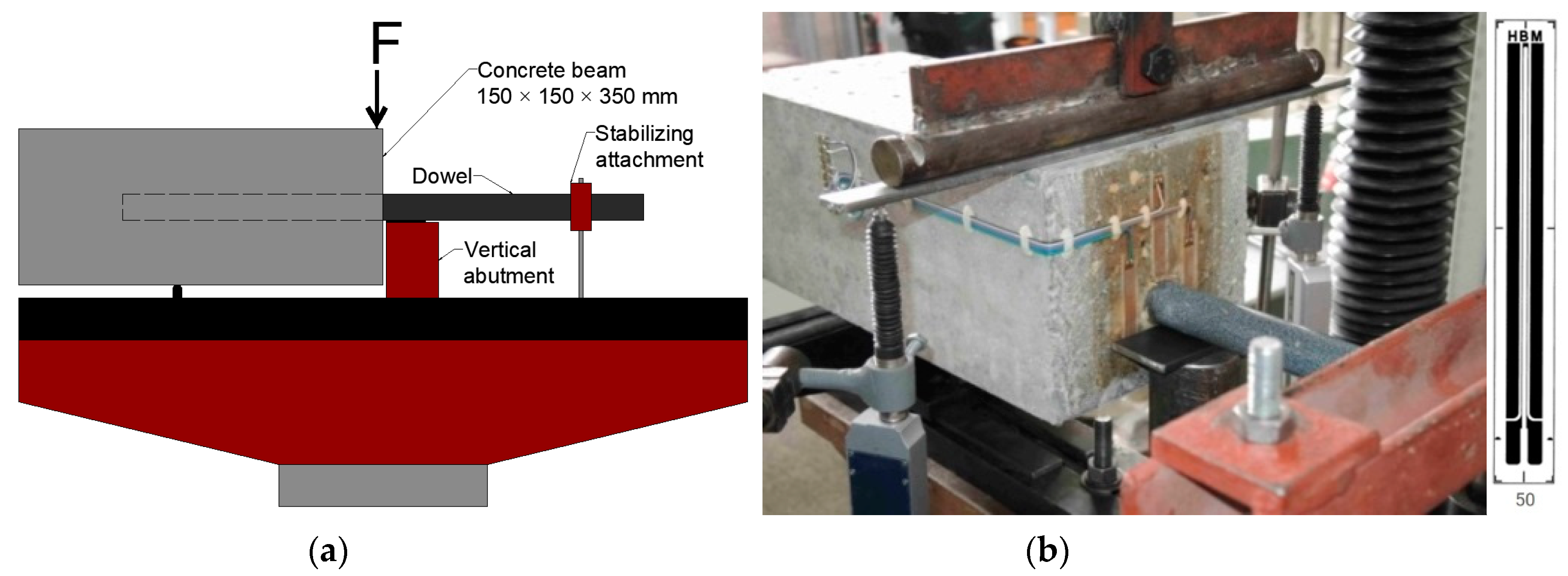
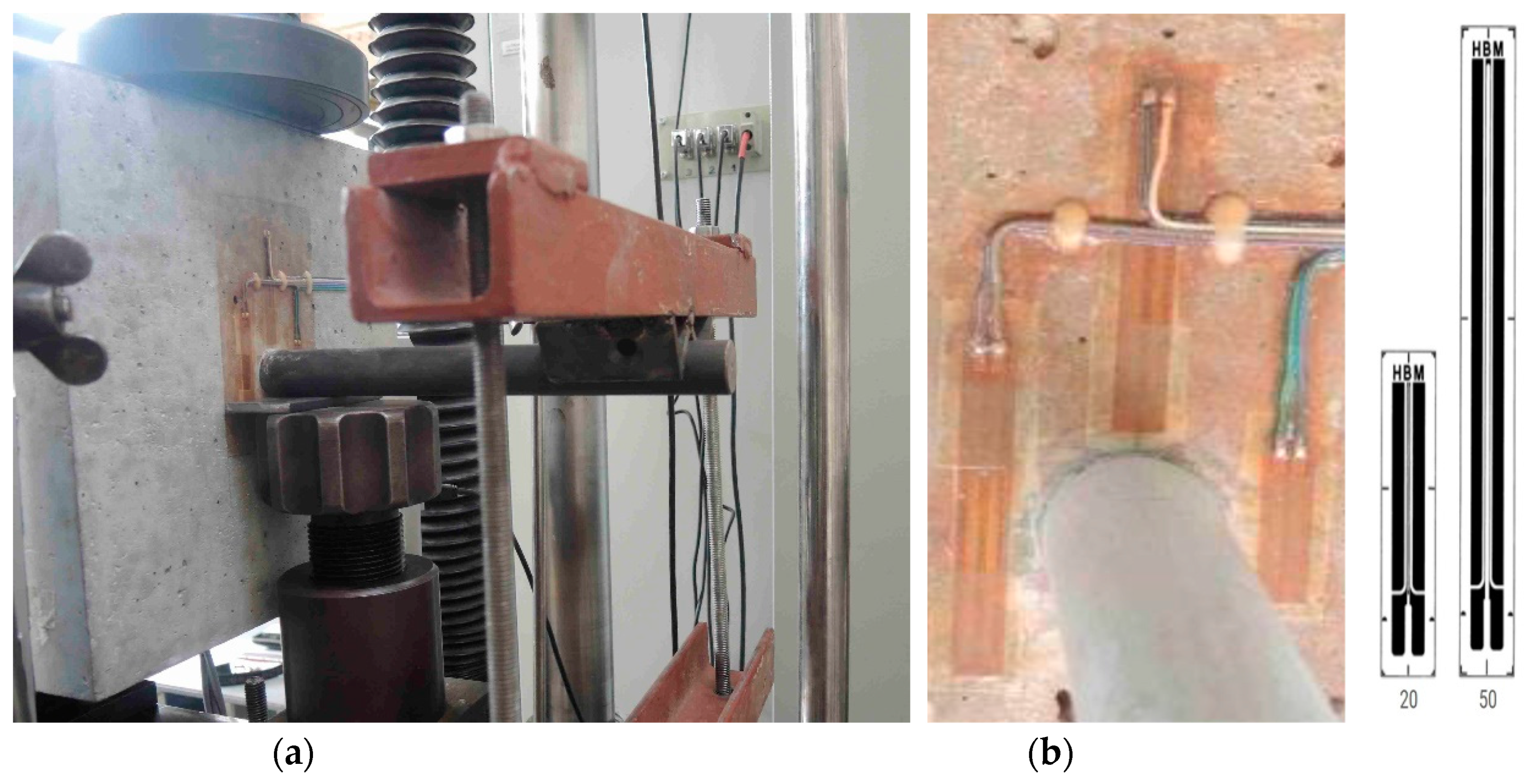
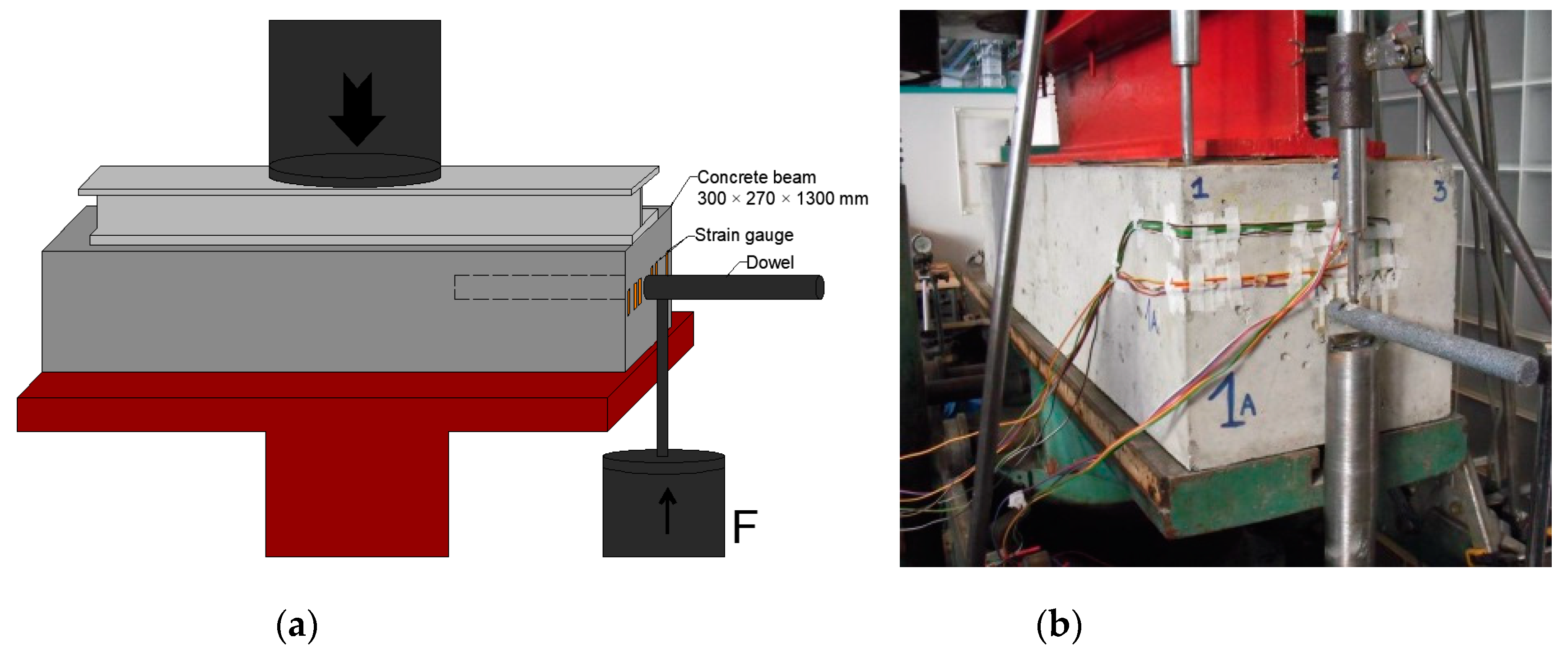
2.1. Czech Loading Test
2.1.1. Cement Concrete Parameters
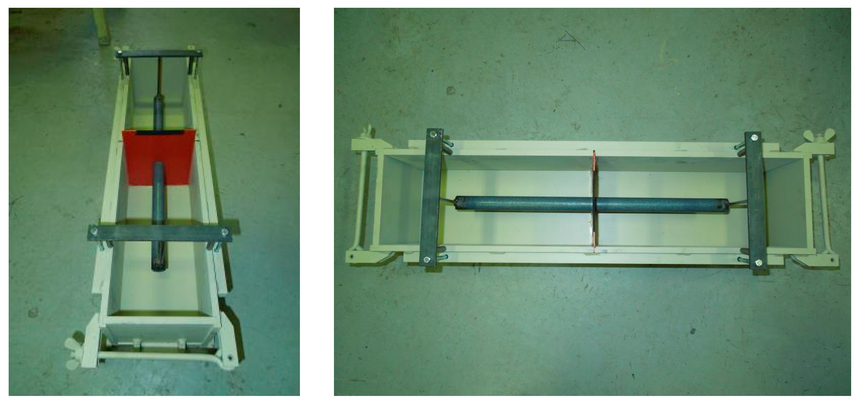
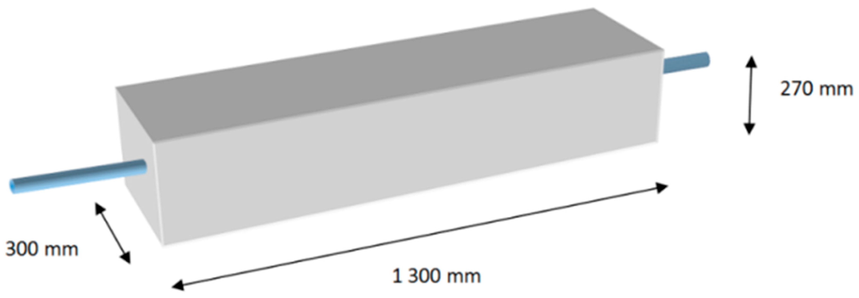
2.1.2. Beams with Incorrectly Inserted Dowels “A”
- basic position (in the middle of the beam);
- vertical translation (downwards—20 mm);
- vertical tilt (towards the force—20 mm).
2.1.3. Beams with Base Position of Dowel “B”
2.1.4. Coating Resistance
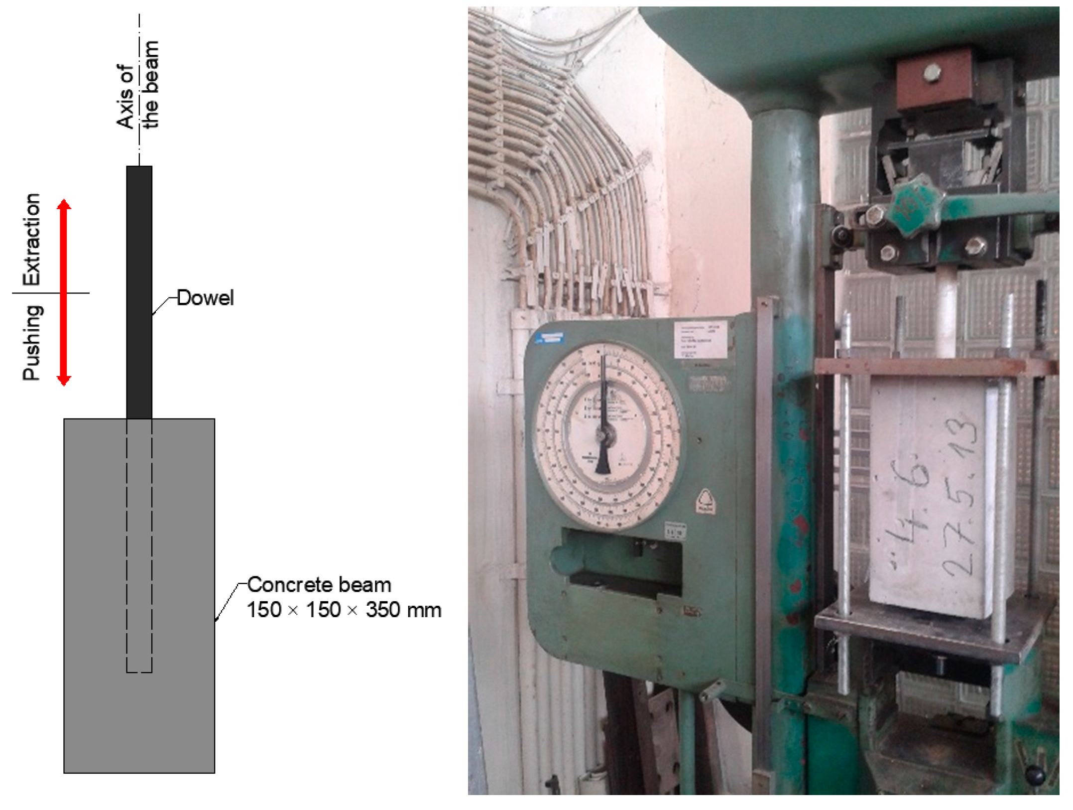
2.1.5. Longitudinal Displacement of Dowels in Cement Concrete
2.2. Slovak Loading Test
3. Results and Discussion
3.1. Czech Loading Test Results
3.1.1. Results on Beam “A”
3.1.2. Results on Beam “B”
3.1.3. Longitudinal Displacement of Dowels in Cement Concrete
3.2. Slovak Loading Test Results
4. Conclusions and Discussions
Author Contributions
Funding
Conflicts of Interest
References
- AASHTO. Guide for Design of Pavement Structures; American Association of State Highway and Transportation Officials: Washington, DC, USA, 1993. [Google Scholar]
- Zienkiewicz, O.; Taylor, R. The Finite Element Method, Fourth Edition; Volume 1: Basic Formulation and Linear Problems; McGraw-Hill: New York, NY, USA, 1994. [Google Scholar]
- Mackiewicz, P. Analysis of stresses in concrete pavement under a dowel according to its diameter and load transfer efficiency. Can. J. Transp. Eng. 2015, 42, 845–853. [Google Scholar] [CrossRef] [Green Version]
- Huang, Y.H. Finite element analysis of slabs on elastic solids. J. Transp. Eng. 1974, 100, 403–416. [Google Scholar]
- Tabatabai, A.M.; Barenberg, E.J. Finite-Element Analysis of Jointed or Cracked Concrete Pavements; Transportation Research Record 671; TRB: Washington, DC, USA, 1978. [Google Scholar]
- Tayabji, S.P.; Colley, B.E. Analysis of Jointed Concrete Pavements; Federal Highway Administration, National Technical Information Service: New York, NY, USA, 1986.
- Shoukry, S.N.; Fahmy, M.; Prucz, J.; William, G. Validation of 3DFE analysis of rigid pavement dynamic response to moving traffic and nonlinear temperature gradient effects. Int. J. Geomech. 2007, 7, 16–24. [Google Scholar] [CrossRef]
- Rousseau, J.; Frangin, E.; Marin, P.; Daudeville, L. Multidomain finite and discrete elements method for impact analysis of a concrete structure. Eng. Struct. 2009, 31, 2735–2743. [Google Scholar] [CrossRef]
- Ding, F.; Yin, Y.; Cai, L.; Tang, Y.; Wang, X. Mechanical Response of Typical Cement Concrete Pavements under Impact Loading. Math. Probl. Eng. 2017, 2017, 2050285. [Google Scholar] [CrossRef] [Green Version]
- Sadeghi, V.; Hesami, S. Investigation of load transfer efficiency in jointed plain concrete pavements (JPCP) using FEM. Int. J. Pavement Res. Technol. 2017, 11, 245–252. [Google Scholar] [CrossRef]
- Li, G.; Chen, C.; Jiang, B.; Shen, Q. Development of prediction model for doweled joint concrete pavement using three-dimensional finite element analysis. Appl. Mech. Mater. 2014, 587–589, 1047–1057. [Google Scholar] [CrossRef]
- Mokhatar, S.; Abdullah, R.; Kueh, A. Computational impact responses of reinforced concrete slabs. Comput. Concr. 2013, 12, 37–51. [Google Scholar] [CrossRef]
- Khazanovich, L.; Neeraj, B.; Alex, G. Evaluation of Alignment Tolerances for Dowels and Their Effects on Joint Performance; Michigan State University: Ann Arbor, MI, USA, 2001. [Google Scholar]
- Shoukry, S.N.; William, G.W.; Riad, M. Application of LS-DYNA in Identifying Critical Stresses Around Dowels. In Proceedings of the 8th International LS-DYNA Users Conference, Detroit, MI, USA, 2–4 May 2004. [Google Scholar]
- Li, L.; Tan, Y.; Gong, X.; Li, Y. Characterization of Contact Stresses between Dowels and Surrounding Concrete in Jointed Concrete Pavement. In Proceedings of the 10th International Conference on Concrete Pavements, Québec, QC, Canada, 8–12 June 2012. [Google Scholar]
- NCC. Recommendations for Standardization of Dowel Load Transfer Systems for Jointed Concrete Roadway Pavements; Iowa State University: Ames, IA, USA, 2011. [Google Scholar]
- NCHRP. Report 637: Guidelines for Dowel Alignment in Concrete Pavements; National Cooperative Highway Research Program: Washington, DC, USA, 2009. [Google Scholar]
- Larson, R.; Smith, K. Evaluation of Alternative Dowel Bar Materials and Coatings; Applied Pavement Technology Inc.: Columbus, OH, USA, 2011. [Google Scholar]
- TP 098. Design of Concrete Pavements on Motorways; Slovak Road Administration: Bratislava, Slovakia, 2015. [Google Scholar]
- ČSN 736123–1. Road Building—Concrete Pavements—Part 1: Construction and Conformity Assessment; Czech Office for Standards, Metrology and Testing: Prague, Czech Republic, 2014. [Google Scholar]
- EN 13877–1. Concrete Pavements—Part 1: Materials; Czech Office for Standards, Metrology and Testing: Prague, Czech Republic, 2006. [Google Scholar]
- EN 13877–3. Concrete Pavements—Part 3: Specification for Dowels to Be Used in Concrete Pavements; Czech Office for Standards, Metrology and Testing: Prague, Czech Republic, 2006. [Google Scholar]
- EN ISO 15630–v1. Steel for the Reinforcement and Prestressing of Concrete–Test Methods–Part 1: Reinforcing Bars, Rods and Wire; Czech Office for Standards, Metrology and Testing: Prague, Czech Republic, 2020. [Google Scholar]
- EN 10060. Hot Rolled Round Steel Bars for General Purposes–Dimensions and Tolerances on Shape and Dimensions; Czech Office for Standards, Metrology and Testing: Prague, Czech Republic, 2004. [Google Scholar]
- ČSN EN 933–1. Tests for Geometrical Properties of Aggregates–Part 1: Determination of Particle Size Distribution–Sieving Method; Czech Office for Standards, Metrology and Testing: Prague, Czech Republic, 2012. [Google Scholar]
- ČSN EN 12350–2. Testing Fresh Concrete–Part 2: Slump-Test; Czech Office for Standards, Metrology and Testing: Prague, Czech Republic, 2009. [Google Scholar]
- ČSN EN 12350–7. Testing Fresh Concrete–Part 7: Air Content–Pressure Methods; Czech Office for Standards, Metrology and Testing: Prague, Czech Republic, 2009. [Google Scholar]
- ČSN EN 12390–3. Testing Hardened Concrete–Part 3: Compressive Strength of Test Specimens; Czech Office for Standards, Metrology and Testing: Prague, Czech Republic, 2019. [Google Scholar]
- ČSN EN 12390–6. Testing Hardened Concrete–Part 6: Tensile Splitting Strength of Test Specimens; Czech Office for Standards, Metrology and Testing: Prague, Czech Republic, 2010. [Google Scholar]
- ČSN 73 1318: Determination of Tensile Strength of Concrete–Z1; Czech Office for Standards, Metrology and Testing: Prague, Czech Republic, 1994.
- ČSN EN 12390-7, Testing Hardened Concrete–Part 7: Density of Hardened Concrete; Czech Office for Standards, Metrology and Testing: Prague, Czech Republic, 2019.
- ČSN ISO 1920-10: Testing of Concrete–Part 10: Determination of Static Modulus of Elasticity in Compression; Czech Office for Standards, Metrology and Testing: Prague, Czech Republic, 2016.
- EA-4/16. Guidelines on the Expression of Uncertainty in Quantitative Testing; European Cooperation for Accreditation: Paris, France, 2003. [Google Scholar]
- Grosek, J.; Zuzulova, A.; Brezina, I. Effectiveness of Dowels in Concrete Pavement. Materials 2019, 12, 1669. [Google Scholar] [CrossRef] [PubMed] [Green Version]
- FHWA-HRT-06-106. Design and Evaluation of Jointed Plain Concrete Pavement with Fiber Reinforced Polymer Dowels; Federal Highway Administration: Washington, DC, USA, 2009.


| Component | Batch Proportions (kg/m3) | Locality |
| CEM I 42.5 R | 375 | Mokra |
| Aggregate 0/4 | 712 | Tovacov |
| Aggregate 4/8 | 178 | Olbramovice |
| Aggregate 8/16 | 534 | Olbramovice |
| Aggregate 11/22 | 356 | Olbramovice |
| Superplasticizer | 3 | - |
| Water | 150 | - |
| Fresh concrete Testing | Value (uncertainty) | - |
| Slump test | 30 mm (±10 mm) | - |
| Air content | 5.9% (±0.2%) | - |
| Hardened Concrete testing | Value (uncertainty) | - |
| Compressive strength | 70.4 MPa (±1.9 MPa) * | - |
| Split tensile strength | 5.6 MPa (±0.4 MPa) * | - |
| Direct tensile strength | 2.9 MPa (±0.6 MPa) * | - |
| Density | 2372 kg/m3 (±30 kg/m3) * | - |
| Modulus of elasticity | 35,900 MPa (±600 MPa) * | |
| w/c ratio | 0.40 (-) | - |
| No. | 1 | 2 | 3 |
|---|---|---|---|
| Coating | PE Plastic | ||
| Diameter (Type, mm) | Smooth Steel, 25 | ||
| Dowel Position | in the Middle | Vertical Translation (Downwards—20 mm) | Vertical Tilt (towards the Force—20 mm) |
| Producer | Czech Republic | ||
| Force [kN] | Tensile stress [MPa] on strain gauges of 50 (20) mm | ||
| 2 | 0.01 (0.01) | 0.02 (0.01) | 0.16 (0.19) |
| 4 | 0.16 (0.26) | 0.17 (0.19) | 0.52 (0.66) |
| 6 | 0.38 (0.62) | 0.43 (0.47) | 0.94 (1.19) |
| 8 | 0.62 (1.01) | 0.72 (0.83) | 1.35 (1.73) |
| 10 | 0.91 (1.42) | 1.03 (1.23) | 1.87 (2.33) |
| Force [kN] | Compressive stress [MPa] on strain gauge of 50 mm | ||
| 2 | 2.99 | 1.27 | 2.15 |
| 4 | 6.41 | 2.94 | 4.90 |
| 6 | 9.76 | 4.70 | 7.55 |
| 8 | 13.04 | 6.58 | 10.23 |
| 10 | 16.24 | 8.59 | 12.95 |
| Force [kN] | Loaded edge deflection [mm] | ||
| 2 | 0.186 | 0.180 | 0.120 |
| 4 | 0.202 | 0.232 | 0.208 |
| 6 | 0.302 | 0.280 | 0.288 |
| 8 | 0.392 | 0.334 | 0.358 |
| 10 | 0.442 | 0.386 | 0.408 |
| No. | 1 | 2 | 3 | 4 | 5 |
|---|---|---|---|---|---|
| Coating | – | PE Plastic | Fiberglass | TUR | PE Plastic |
| Shore A Hardness Test (-) | - | 50 | 90 | 75 | 50 |
| Diameter (Type, mm) | Smooth Steel 25 | ||||
| Dowel Position | in the Middle of Beam | ||||
| Producer | Czech Republic | Czech Republic | Czech Republic | Czech Republic | Germany |
| Force [kN] | Tensile stress [MPa] on strain gauges of 50 (20) mm | ||||
| 2 | 0.15 (0.25) | 0.15 (0.35) | 0.03 (0.10) | 0.16 (0.20) | 0.26 (0.24) |
| 4 | 0.36 (0.73) | 0.50 (1.19) | 0.20 (0.59) | 0.45 (0.66) | 0.70 (0.94) |
| 6 | 0.62 (1.31) | 0.88 (2.17) | 0.38 (1.17) | 0.76 (1.14) | 1.17 (1.76) |
| 8 | 0.90 (2.19) | 1.26 (3.19) | 0.63 (1.96) | 1.13 (1.71) | 1.70 (2.69) |
| 10 | 1.23 (3.32) | 1.65 (4.22) | 0.91 (2.78) | 1.55 (2.37) | 2.30 (3.93) |
| Force [kN] | Compressive stress [MPa] on strain gauge of 50 mm | ||||
| 2 | 1.20 | 1.11 | 1.01 | 0.93 | 0.71 |
| 4 | 2.51 | 3.12 | 2.35 | 2.40 | 2.31 |
| 6 | 3.85 | 5.11 | 3.69 | 3.90 | 4.02 |
| 8 | 5.31 | 7.04 | 5.16 | 5.53 | 5.73 |
| 10 | 6.82 | 8.95 | 6.62 | 7.28 | 7.73 |
| Force [kN] | Loaded edge deflection [mm] | ||||
| 2 | 0.072 | 0.102 | 0.036 | 0.030 | 0.136 |
| 4 | 0.114 | 0.154 | 0.106 | 0.088 | 0.210 |
| 6 | 0.150 | 0.204 | 0.154 | 0.128 | 0.274 |
| 8 | 0.176 | 0.250 | 0.198 | 0.170 | 0.328 |
| 10 | 0.204 | 0.288 | 0.240 | 0.210 | 0.366 |
| Type | Test Number | Dowel Diameter [mm] | Maximum Extraction Force [kN] | Maximum Extrusion Force [kN] |
|---|---|---|---|---|
| PE Plastic | 1 | 25 | 64.0 | 42.0 |
| 2 | 37.8 | 34.0 | ||
| 3 | 32.6 | 29.6 | ||
| 4 | 29.2 | 25.8 | ||
| 5 | 26.4 | 22.8 | ||
| 6 | 24.7 | 20.5 | ||
| 7 | 22.0 | 18.3 | ||
| 8 | 20.8 | 16.8 | ||
| 9 | 18.8 | 15.3 | ||
| 10 | 17.4 | 13.5 | ||
| TUR | 1 | 25 | 22.0 | 17.0 |
| 2 | 14.6 | 14.0 | ||
| 3 | 13.2 | 14.0 | ||
| 4 | 12.7 | 14.0 | ||
| 5 | 12.5 | 13.6 | ||
| 6 | 12.5 | 13.2 | ||
| 7 | 12.0 | 12.8 | ||
| 8 | 11.4 | 12.4 | ||
| 9 | 11.2 | 12.4 | ||
| 10 | 10.8 | 12.4 | ||
| Fiberglass | 1 | 25 | 62.7 | 69.1 |
| 2 | 46.8 | 45.0 | ||
| 3 | 44.3 | 41.2 | ||
| 4 | 43.3 | 39.9 | ||
| 5 | 42.5 | 38.3 | ||
| 6 | 39.8 | 38.5 | ||
| 7 | 39.1 | 34.3 | ||
| 8 | 37.3 | 33.2 | ||
| 9 | 28.3 | 33.7 | ||
| 10 | 26.3 | 32.3 |
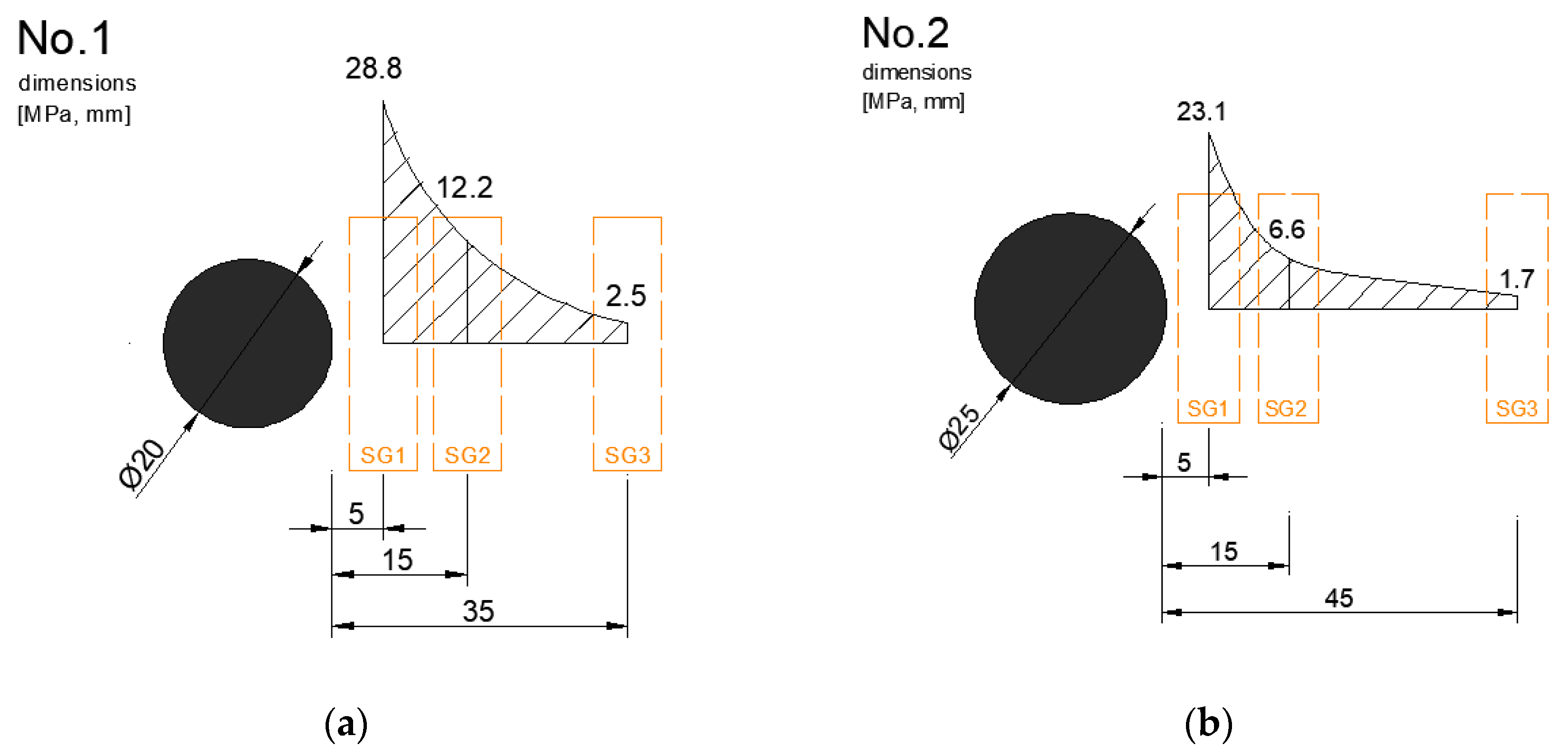
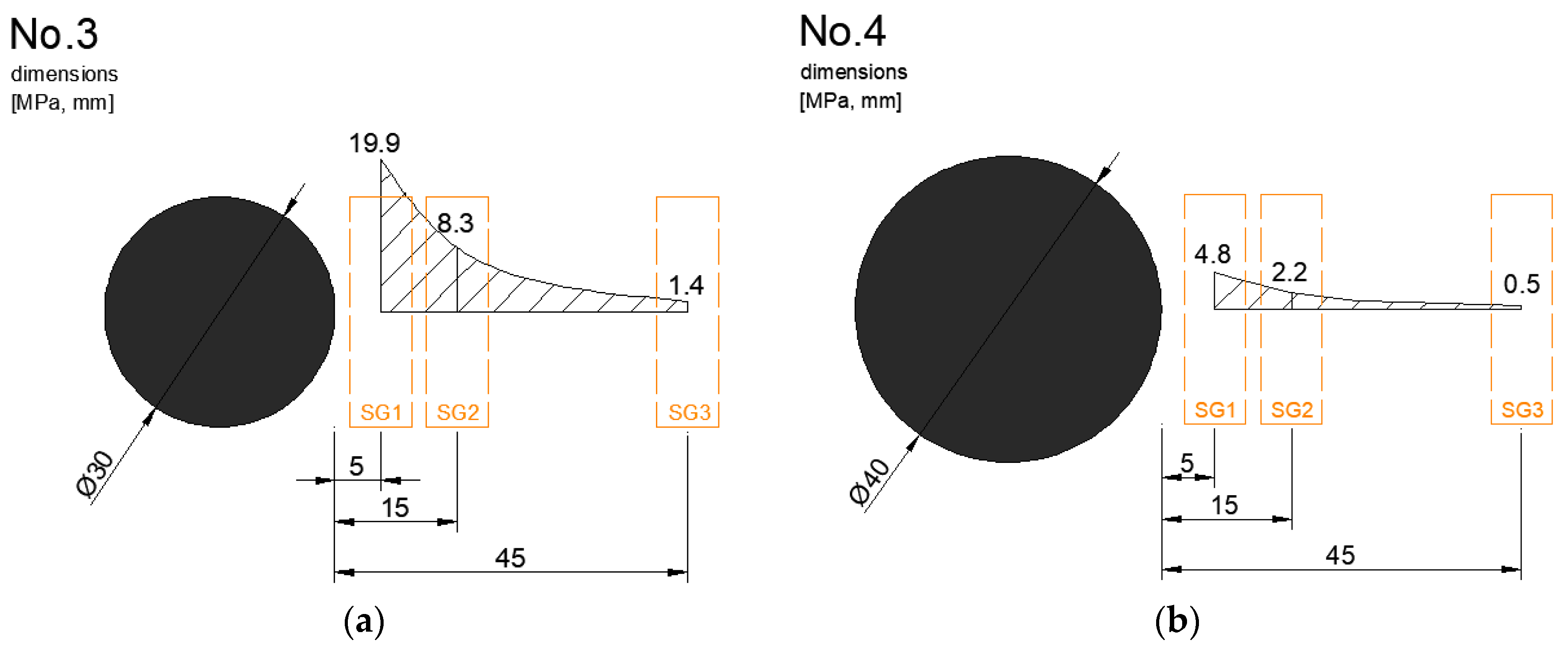
| No. | Dowel Diameter (mm) | Stress (MPa) | ||
|---|---|---|---|---|
| SG1 | SG2 | SG3 | ||
| 1 | 20 | 28.8 | 12.2 | 2.5 |
| 2 | 25 | 23.1 | 6.6 | 1.7 |
| 3 | 30 | 19.9 | 8.3 | 1.4 |
| 4 | 40 | 4.8 | 2.2 | 0.5 |
© 2020 by the authors. Licensee MDPI, Basel, Switzerland. This article is an open access article distributed under the terms and conditions of the Creative Commons Attribution (CC BY) license (http://creativecommons.org/licenses/by/4.0/).
Share and Cite
Zuzulova, A.; Grosek, J.; Janku, M. Experimental Laboratory Testing on Behavior of Dowels in Concrete Pavements. Materials 2020, 13, 2343. https://doi.org/10.3390/ma13102343
Zuzulova A, Grosek J, Janku M. Experimental Laboratory Testing on Behavior of Dowels in Concrete Pavements. Materials. 2020; 13(10):2343. https://doi.org/10.3390/ma13102343
Chicago/Turabian StyleZuzulova, Andrea, Jiri Grosek, and Michal Janku. 2020. "Experimental Laboratory Testing on Behavior of Dowels in Concrete Pavements" Materials 13, no. 10: 2343. https://doi.org/10.3390/ma13102343