1. Introduction
In civil engineering, steel corrosion is considered as the main factor for the insufficient durability of concrete structures [
1,
2]. The bearing capacity of the structure is significantly decreased with the reduced steel section area and the weakened bonding strength, leading to the structural failure in advance and a huge economic loss. It is necessary to solve this intractable issue to extend structural service life, especially under the marine environment. As a kind of composite material, carbon fiber reinforced polymer (CFRP) possesses excellent properties, such as high tensile strength, good corrosion resistance, and is lightweight [
3,
4,
5,
6,
7], making it an ideal alternative reinforcement to effectively prevent the steel corrosion. However, the FRP bar is brittle with low elastic modulus and high price, hindering the large-scale application in civil engineering [
8,
9].
To overcome the drawbacks of FRP bar and steel bar for concrete beams, a number of methods have been proposed, including composite bar and hybrid reinforcement system. Combining the advantages of steel bars and FRP materials, a new composite bar has been proposed recently: The steel fiber reinforced polymer composite bar (SFCB) with steel bar as the inner core, CFRP material as the outer layer, and resin as the bonding material [
10,
11]. Although the properties of SFCB have been verified experimentally including high elastic modulus and stable post-yield stiffness as well as excellent corrosive resistance, it has not yet been implemented completely in practical engineering. Additionally, due to the complexity of the manufacturing process, micropores and microcracks exist inevitably inside the composite bar, leading to the corrosion of the internal steel bar under adverse environments [
12]. On the other hand, a hybrid reinforcement form for concrete structures has attracted lots of attention in the past few decades [
13,
14,
15,
16]. In the hybrid-reinforced concrete beams, the anticorrosive FRP bars are arranged in the corner area, which is more prone to corrosion, while the ductile steel bars are arranged inside the section. Based on the complementary advantages of two materials, such a hybrid reinforcement system is featured with improved ductility and enhanced bearing capacity compared with purely steel-reinforced concrete beams and FRP-reinforced concrete beams [
15]. Many studies in the aspect of the flexural behavior for the hybrid-reinforced concrete beam have been conducted experimentally and numerically [
13,
17]. Although the hybrid reinforcement system is highly anticorrosive with enough ductility and promising application prospects, the internal steel bar is still vulnerable to corrosion in a high chloride environment. Other measures are required to further protect this system from corrosion in severe conditions.
Impressed current cathodic protection (ICCP) is an effective method to restrain steel corrosion [
18,
19,
20]. In the ICCP system, the steel bar is connected to the negative pole of the direct current (DC) power supply, and the auxiliary anode material is connected to the positive pole. A current is applied to the steel bar to make the steel bar become a cathode and enough electrons are transferred to the surface of the steel bar, leading to the inhibition of the electron migration caused by steel corrosion. Therefore, the corrosion of the steel bar can be effectively avoided or lessened. It is well known that the successful application of ICCP largely depends on the selection of the appropriate anode material, including metalized zinc [
21], conductive organic paints [
22], activated titanium mesh [
23], and coating-overlay anodes [
24]. Unfortunately, these materials are either suffering from durability problems or are highly expensive, hindering the wide application of the ICCP technique in civil engineering. Owing to the excellent conductivity and electrochemical properties as well as corrosion resistance, CFRP is an ideal anode material and has been widely studied for the ICCP system in the last decade [
25,
26]. In the study of Sun et al. in 2016 [
26], the corrosion behavior of CFRP laminate as the anodic material was focused with 3% NaCl solution, and the electrochemical performance as well as mechanical properties were identified. Recently, a dual function of CFRP in the ICCP system was demonstrated, i.e., externally bonded CFRP functioned as both the anode material for ICCP and strengthening material for structural strengthening system simultaneously [
27,
28,
29,
30,
31]. However, to ensure the bonding reliability between the externally bonded CFRP and the concrete, as well as to improve the reinforcing effectiveness of the CFRP, developing an efficient conductive inorganic binder is urgent, which restricts the application of this system.
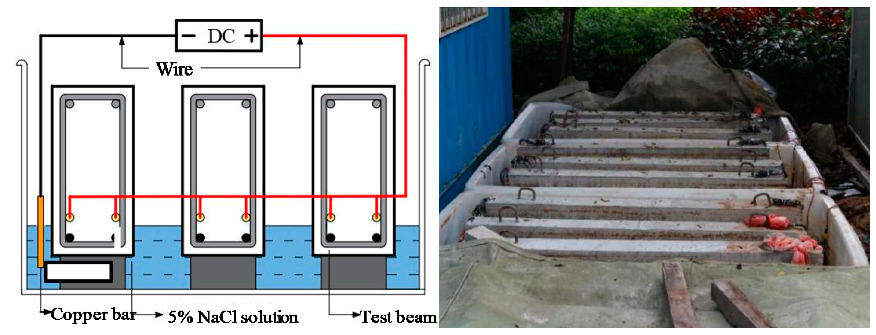
Aiming at these issues, to further inhibit steel corrosion in a high chloride environment and take advantage of the dual-functional CFRP without the drawback of interface adhesive, the ICCP technique was applied to the hybrid-reinforced concrete (RC) beam with internally embedded CFRP bars and SFCB as the anode material in this paper, as shown in
Figure 1 (the RC beam can be seen in
Figure 2). In the hybrid-reinforced concrete beams, the anticorrosive CFRP bars and SFCBs were arranged in the lower layer while the ductile steel bars were arranged in the upper layer. The effect of the new ICCP system on the flexural performance of the hybrid-reinforced concrete beam subjected to corrosion was verified experimentally. First, to accelerate the dry–wet cycles corrosion in the whole process, an electricity-accelerated precorrosion test was performed for the steel bar in the hybrid-reinforced beams with a target corrosion ratio of 5%. Then, the dry–wet cycles corrosion was conducted and the ICCP system was activated simultaneously for the hybrid-reinforced concrete beam for 180 days. Finally, the three-point flexural experiment was carried out for the simply supported hybrid-reinforced concrete beams. After the tests, the steel bar was taken out from the concrete to quantitatively measure the steel corrosion. Results showed that the process of steel corrosion could be inhibited effectively by the ICCP treatment with the CFRP bar and the SFCB as the anode material. Additionally, the ICCP system showed an obvious effect on the flexural performance of the hybrid-reinforced concrete beams, especially for the CFRP anode. Compared with the SFCB anode, the ICCP system with the CFRP bar as the anode was more effective for the hybrid-reinforced concrete beam to prevent the steel corrosion. In general, the key issue of this paper was to investigate the flexural performance of hybrid RC beams with CFRP bar or SFCB as the anode material in the ICCP system subjected to corrosion, leading to the differences in CFRP type and test contents compared with other references [
26,
28]. Furthermore, considering the sea sand and seawater utilized and dry–wet cycle corrosion performed in this experiment, it can be inferred that the new ICCP system is a promising method to protect the steel bar subjected to the marine environment, and can further promote the utilization of sea sand and seawater in civil engineering.
4. Conclusions
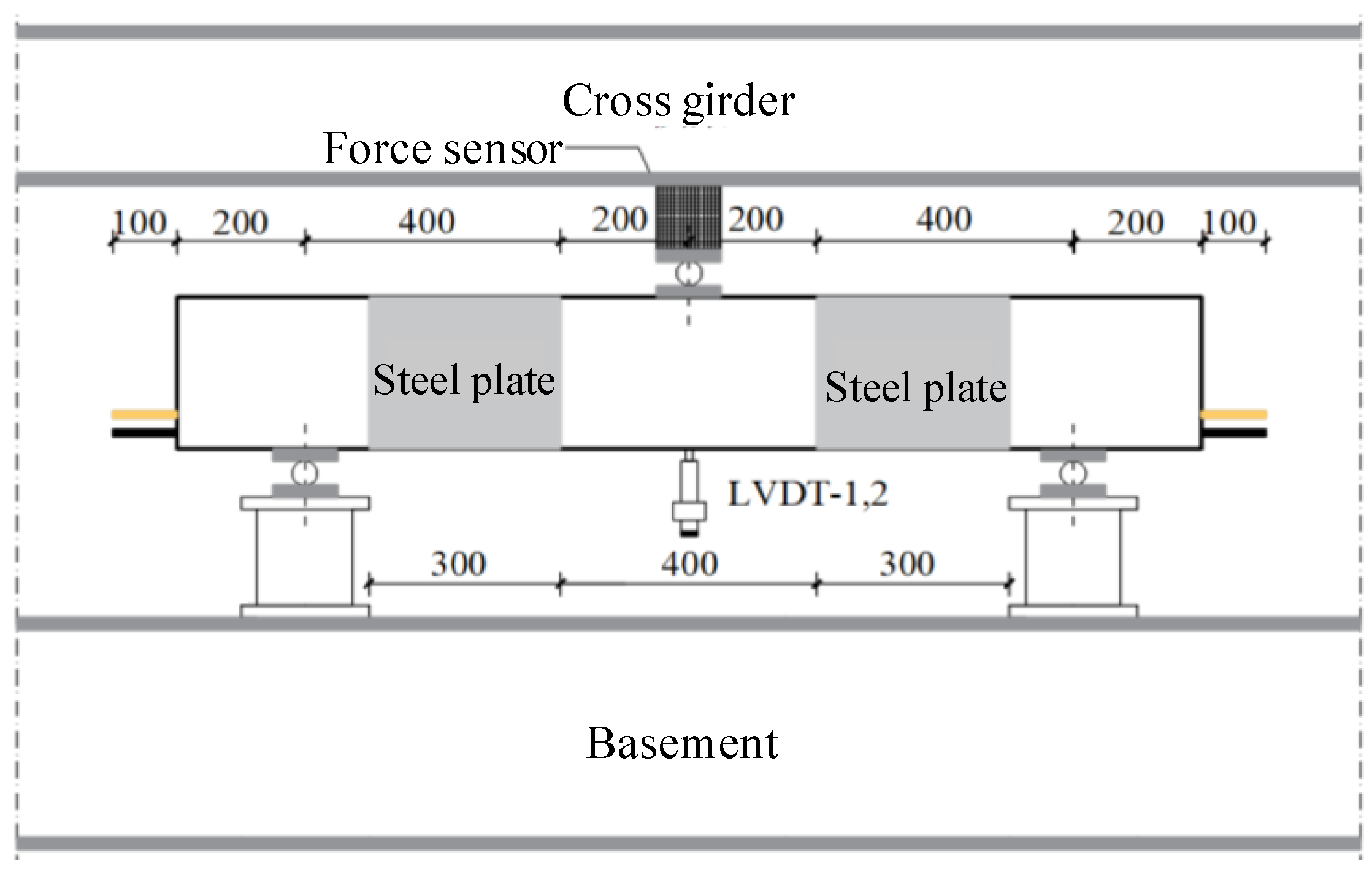
In this paper, to further inhibit steel corrosion in a high chloride environment and take advantage of the dual-functional CFRP, the ICCP technique was applied to the hybrid-reinforced concrete beam with internally embedded CFRP bars and SFCBs as the anode material. In the hybrid-reinforced concrete beams, the anticorrosive CFRP bars and SFCBs were arranged in the corner area of stirrups where it is more prone to suffer from corrosion while the ductile steel bars were arranged above. The effect of the new ICCP system on the flexural behavior of the hybrid-reinforced concrete beam was verified experimentally in a severe environment. First, the electricity-accelerated precorrosion was performed for the steel bars in the hybrid-reinforced beams with a target corrosion ratio of 5%. Then, the dry–wet cycles corrosion was conducted and the ICCP system was activated for the hybrid-reinforced concrete beam for 180 days. Finally, the three-point flexural experiment was carried out for the hybrid-reinforced concrete beams. The steel bars were taken out from the concrete to quantitatively measure the corrosion ratio after flexural tests. Based on this study, the following conclusions can be drawn:
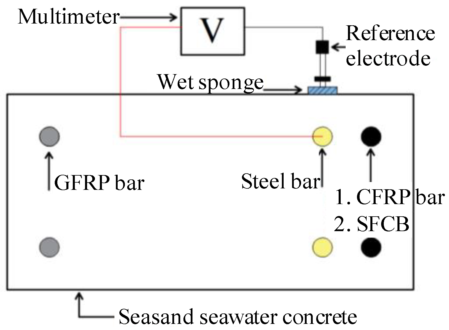
(1) With the CFRP bar and the SFCB as the anode material, the process of steel corrosion was inhibited effectively by the ICCP system. Compared with the steel bar without ICCP treatment, the self-corrosion potential of the steel bar was developing towards the corrosion immunity zone, and the loss of the line density was decreased. Furthermore, considering the sea sand and seawater utilized and the dry–wet cycle corrosion performed in this experiment, it can be inferred that the new ICCP system is a promising method to protect the steel bar subjected to the marine environment, and can further promote the utilization of sea sand and seawater in civil engineering.
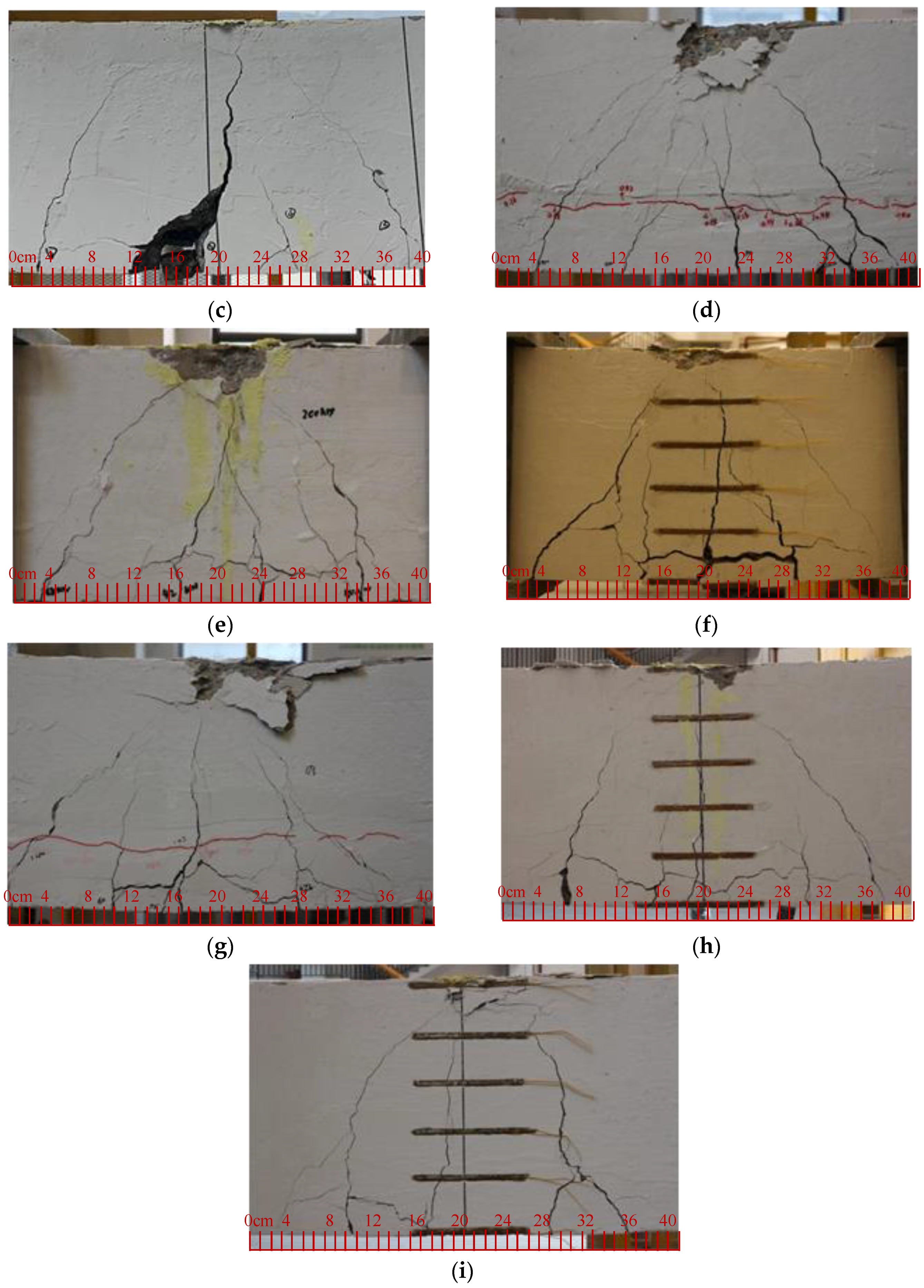
(2) The ICCP system showed an obvious effect on the flexural performance of the hybrid-reinforced concrete beams. Compared with the hybrid RC beam without ICCP treatment, the crack load and ultimate load, as well as the stiffness, were enhanced notably. However, there was no distinguished difference of crack number and width between the beams with ICCP treatment and without ICCP treatment.
(3) Compared with the SFCB anode, the ICCP system with the CFRP bar as the anode material was more effective for the hybrid-reinforced concrete beam to prevent the steel corrosion. This can be confirmed by the result of the line density loss of the steel bar. There existed a deterioration of the carbon fiber on the surface of SFCB with ICCP, leading to the degradation in the mechanical properties of SFCB, which can be further verified by the result of self-corrosion potential and the ultimate load capacity.


