Microstructural Evolution and Mechanical Properties of an Advanced γ-TiAl Based Alloy Processed by Spark Plasma Sintering


Abstract
:1. Introduction
2. Experimental Procedure
3. Results
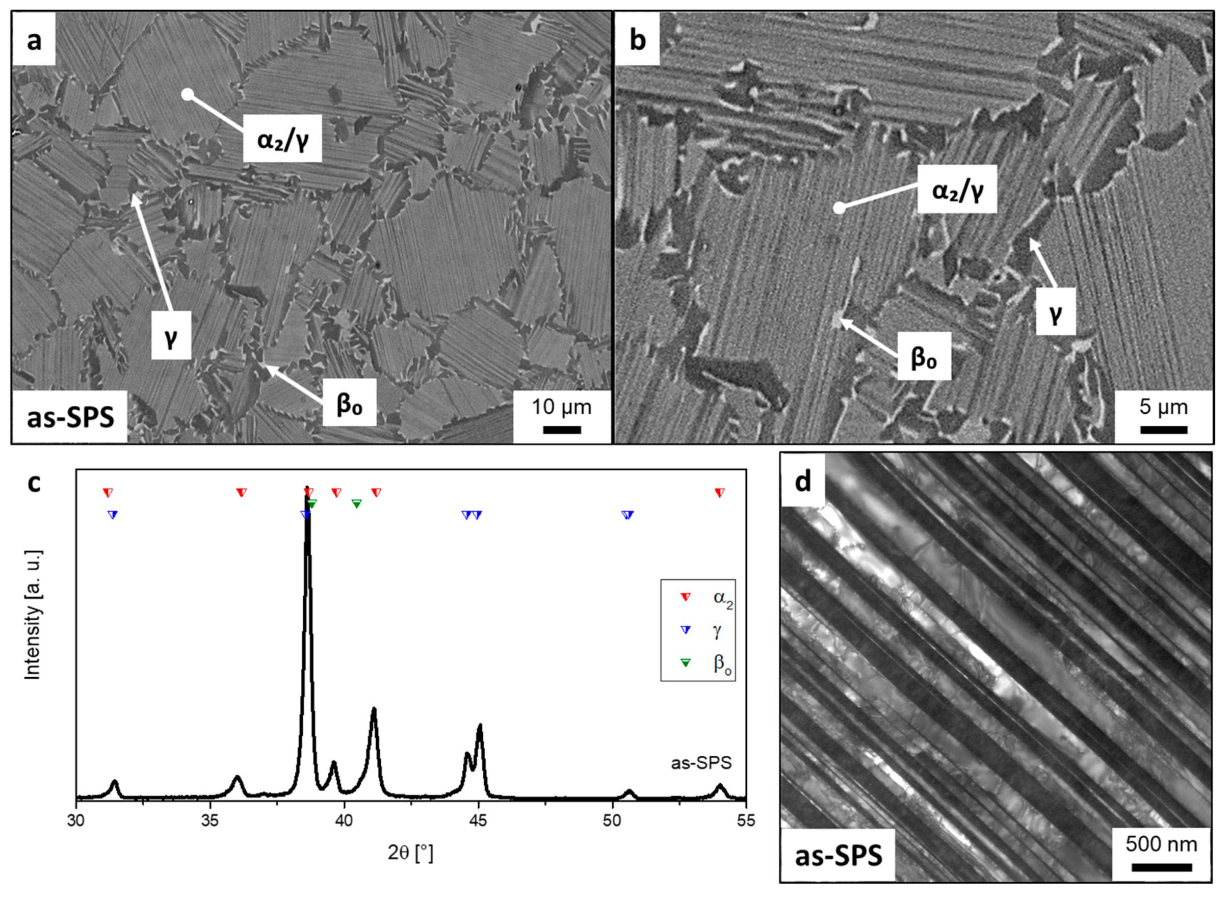
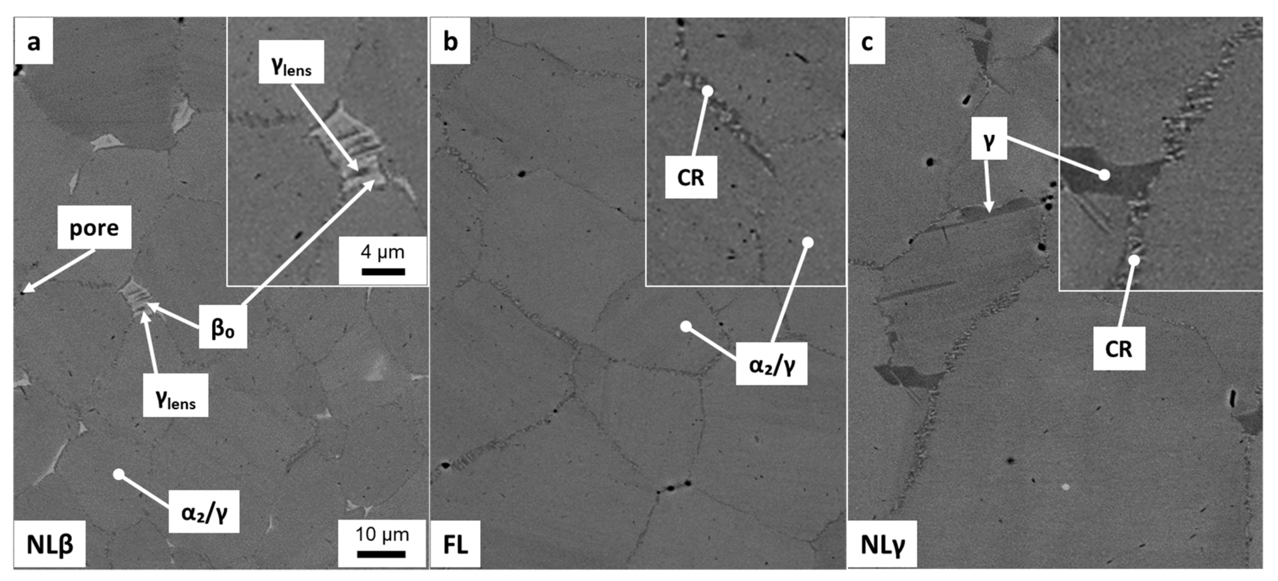
3.1. Microstructure
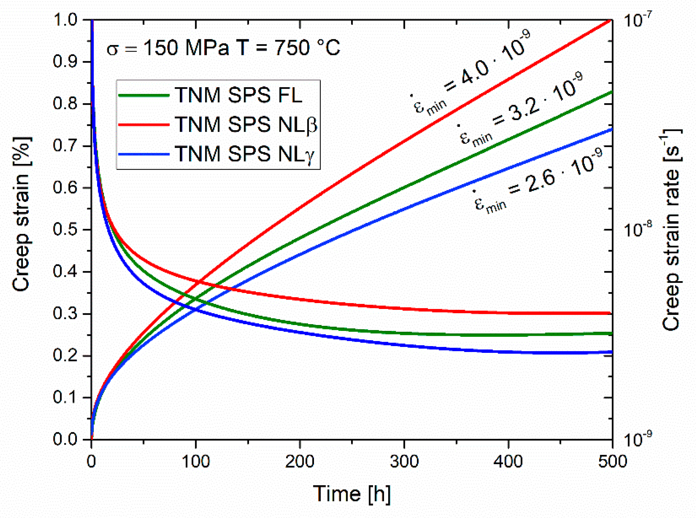
3.2. Mechanical Testing
4. Discussion
5. Summary
Author Contributions
Funding
Acknowledgments
Conflicts of Interest
References
- Mayer, S.; Erdely, P.; Fischer, F.D.; Holec, D.; Kastenhuber, M.; Klein, T.; Clemens, H. Intermetallic β-solidifying γ-TiAl based alloys—From fundamental research to application. Adv. Eng. Mater. 2017, 19, 1600735. [Google Scholar] [CrossRef]
- Clemens, H.; Mayer, S. Design, processing, microstructure, properties, and applications of advanced intermetallic TiAl alloys. Adv. Eng. Mater. 2013, 15, 191–215. [Google Scholar] [CrossRef]
- Habel, U.; Heutling, F.; Kunze, C.; Smarsly, W.; Das, C.; Clemens, H. Forged Intermetallic γ-TiAl Based Alloy Low Pressure Turbine Blade in the Geared Turbofan. In Proceedings of the 13th World Conference on Titanium, San Diego, CA, USA, 16–20 August 2015; Venkatesh, V., Pilchak, A.L., Allison, J.E., Ankern, S., Boyer, R., Christodoulou, J., Fraser, H.L., Imam, M.A., Kosaka, Y., Rack, H.J., et al., Eds.; John Wiley & Sons, Inc.: Hoboken, NJ, USA, 2016; pp. 1223–1227. [Google Scholar]
- Bewlay, B.P.; Nag, S.; Suzuki, A.; Weimer, M.J. TiAl alloys in commercial aircraft engines. Mater. High Temp. 2016, 33, 549–559. [Google Scholar] [CrossRef]
- Clemens, H.; Wallgram, W.; Kremmer, S.; Güther, V.; Otto, A.; Bartels, A. Design of novel β-solidifying TiAl alloys with adjustable β/B2-phase fraction and excellent hot-workability. Adv. Eng. Mater. 2008, 10, 707–713. [Google Scholar] [CrossRef]
- Couret, A.; Voisin, T.; Thomas, M.; Monchoux, J.-P. Development of a TiAl alloy by spark plasma sintering. JOM 2017, 69, 2576–2582. [Google Scholar] [CrossRef]
- Voisin, T.; Monchoux, J.-P.; Durand, L.; Karnatak, N.; Thomas, M.; Couret, A. An innovative way to produce γ-TiAl blades. Adv. Eng. Mater. 2015, 17, 1408–1413. [Google Scholar] [CrossRef]
- Voisin, T.; Monchoux, J.-P.; Hantcherli, M.; Mayer, S.; Clemens, H.; Couret, A. Microstructures and mechanical properties of a multi-phase β-solidifying TiAl alloy densified by spark plasma sintering. Acta Mater. 2014, 73, 107–115. [Google Scholar] [CrossRef]
- Schwaighofer, E.; Clemens, H.; Mayer, S.; Lindemann, J.; Klose, J.; Smarsly, W.; Güther, V. Microstructural design and mechanical properties of a cast and heat-treated intermetallic multi-phase γ-TiAl based alloy. Intermetallics 2014, 44, 128–140. [Google Scholar] [CrossRef]
- Appel, F.; Paul, J.D.H.; Oehring, M. Gamma Titanium Aluminide Alloys; Wiley-VCH: Weinheim, Germany, 2009. [Google Scholar]
- Kim, Y.-W. Microstructural evolution and mechanical properties of a forged gamma titanium aluminide alloy. Acta Metal. Mater. 1992, 40, 1121–1134. [Google Scholar] [CrossRef]
- Mayer, S.; Kastenhuber, M.; Clemens, H. Advanced titanium aluminides - how to improve the creep resistance via compositional and microstructural optimization. Mater. Sci. Forum 2018, 941, 1484–1489. [Google Scholar] [CrossRef]
- Takeyama, M.; Nakamura, M.; Kumagai, T.; Kikuchi, M. Cooling rate dependence of the α/γ phase transformation in titanium aluminides and its application to alloy development. Struct. Intermet. 1993, 167–176. Available online: https://jglobal.jst.go.jp/en/detail?JGLOBAL_ID=200902116917348286&rel=0 (accessed on 12 April 2019).
- Beschliesser, M.; Chatterjee, A.; Lorich, A.; Knabl, W.; Kestler, H.; Dehm, G.; Clemens, H. Designed fully lamellar microstructures in a γ-TiAl based alloy: Adjustment and microstructural changes upon long-term isothermal exposure at 700 and 800 °C. Mater. Sci. Eng. A 2002, 329, 124–129. [Google Scholar] [CrossRef]
- Wallgram, W.; Schmölzer, T.; Cha, L.; Das, G.; Güther, V.; Clemens, H. Technology and mechanical properties of advanced γ-TiAl based alloys. Int. J. Mater. Res. 2009, 100, 1021–1030. [Google Scholar] [CrossRef]
- Klein, T.; Clemens, H.; Mayer, S. Advancement of compositional and microstructural design of intermetallic γ-TiAl based alloys determined by atom probe tomography. Materials 2016, 9, 755. [Google Scholar] [CrossRef]
- Kastenhuber, M.; Klein, T.; Clemens, H.; Mayer, S. Tailoring microstructure and chemical composition of advanced γ-TiAl based alloys for improved creep resistance. Intermetallics 2018, 97, 27–33. [Google Scholar] [CrossRef]
- Schloffer, M.; Iqbal, F.; Gabrisch, H.; Schwaighofer, E.; Schimansky, F.-P.; Mayer, S.; Stark, A.; Lippmann, T.; Göken, M.; Pyczak, F.; et al. Microstructure development and hardness of a powder metallurgical multi phase γ-TiAl based alloy. Intermetallics 2012, 22, 231–240. [Google Scholar] [CrossRef] [Green Version]
- Gerling, R.; Clemens, H.; Schimansky, F.P. Powder metallurgical processing of intermetallic gamma titanium aluminides. Adv. Eng. Mater. 2004, 6, 23–38. [Google Scholar] [CrossRef]
- Schatt, W.; Wieters, K.-P.; Kieback, B. Pulvermetallurgie: Technologien und Werkstoffe; Springer: Berlin/Heidelberg, Germany, 2002. [Google Scholar]
- Achtermann, M.; Fürwitt, W.; Güther, V.; Nicolai, H.-P. Method for Producing of γ-TiAl base Alloy. European Patent EP2342365, 13 July 2011. [Google Scholar]
- Güther, V.; Allen, M.; Klose, J.; Clemens, H. Metallurgical processing of titanium aluminides on industrial scale. Intermetallics 2018, 103, 12–22. [Google Scholar] [CrossRef]
- Voisin, T.; Durand, L.; Karnatak, N.; Gallet, S.L.; Thomas, M.; Berre, Y.L.; Castagné, J.-F.; Couret, A. Temperature control during spark plasma sintering and application to up-scaling and complex shaping. J. Mater. Process. Technol. 2013, 213, 269–278. [Google Scholar] [CrossRef]
- Schloffer, M.; Schmoelzer, T.; Mayer, S.; Schwaighofer, E.; Hawranek, G.; Schimansky, F.-P.; Pyczak, F.; Clemens, H. The characterisation of a powder metallurgically manufactured TNM™ titanium aluminide alloy using complimentary quantitative methods. Pract. Metall. 2011, 48, 594–604. [Google Scholar] [CrossRef]
- McCusker, L.B.; Dreele, R.B.V.; Cox, D.E.; Louër, D.; Scardi, P. Rietveld refinement guidelines. J. Appl. Crystallogr. 1999, 32, 36–50. [Google Scholar] [CrossRef] [Green Version]
- Cha, L.; Clemens, H.; Dehm, G. Microstructure evolution and mechanical properties of an intermetallic Ti-43.5Al-4Nb-1Mo-0.1B alloy after ageing below the eutectoid temperature. Int. J. Mater. Res. 2011, 102, 703–708. [Google Scholar] [CrossRef]
- Kastenhuber, M.; Klein, T.; Rashkova, B.; Weißensteiner, I.; Clemens, H.; Mayer, S. Phase transformations in a β-solidifying γ-TiAl based alloy during rapid solidification. Intermetallics 2017, 91, 100–109. [Google Scholar] [CrossRef]
- Lamirand, M.; Bonnentien, J.-L.; Guérin, S.; Ferrière, G.; Chevalier, J.-P. Effects of interstitial oxygen on microstructure and mechanical properties of Ti-48Al-2Cr-2Nb with fully lamellar and duplex microstructures. Metall. Mater. Trans. A 2006, 37, 2369–2378. [Google Scholar] [CrossRef]
- Ding, H.; Nie, G.; Chen, R.; Guo, J.; Fu, H. Influence of oxygen on microstructure and mechanical properties of directionally solidified Ti–47Al–2Cr–2Nb alloy. Mater. Des. 2012, 41, 108–113. [Google Scholar] [CrossRef]
- Lefebvre, W.; Menand, A.; Loiseau, A. Influence of oxygen on phase transformations in a Ti-48 At. pct Al alloy. Metall. Mater. Trans. A 2003, 34, 2067–2075. [Google Scholar] [CrossRef]
- Wegmann, G.; Gerling, R.; Schimansky, F.-P. Temperature induced porosity in hot isostatically pressed gamma titanium aluminide alloy powders. Acta Mater. 2003, 51, 741–752. [Google Scholar] [CrossRef]
- Wimler, D.; Kardos, S.; Lindemann, J.; Clemens, H.; Mayer, S. Aspects of powder characterization for additive manufacturing. Pract. Metallogr. 2018, 55, 620–636. [Google Scholar] [CrossRef]
- Dlouhý, A.; Kuchařová, K. Creep and microstructure of near-gamma TiAl alloys. Intermetallics 2004, 12, 705–711. [Google Scholar] [CrossRef]
- Maruyama, K.; Yamamoto, R.; Nakakuki, H.; Fujitsuna, N. Effects of lamellar spacing, volume fraction and grain size on creep strength of fully lamellar TiAl alloys. Mater. Sci. Eng. A 1997, 239–240, 419–428. [Google Scholar] [CrossRef]


| Ti | Al | Nb | Mo | B | O |
|---|---|---|---|---|---|
| bal. | 43.45 | 4.05 | 1.02 | 0.10 | 1300 |
| Type of Microstructure | Heat Treatment | Phase Fractions Measured via XRD * | Quantitative Morphological Analysis of SEM Micrographs ** | Lamellar Spacing | Hardness | |||||
|---|---|---|---|---|---|---|---|---|---|---|
| α2 | γ | βo | α2/γ-colonies | globular γ | βo+γlens | |||||
| [vol.%] | [vol.%] | [vol.%] | fraction [vol.%] | size [µm] | fraction [vol.%] | fraction [vol.%] | [nm] | [HV10] | ||
| as-SPS | - | 35 | 61 | 4 | 94 | 19 | 5 | <1 | 83 ± 7 | 378 ± 8 |
| NLβ | 1290 °C/30 min/AC + 850 °C/6 h/FC | 27 | 71 | ≤2 | 97 | 20 | <1 | 2 | 8 ± 9 | 466 ± 4 |
| FL | 1265 °C/ 30 min/AC + 850 °C/6 h/FC | 30 | 68 | ≤2 | 98 | 29 | <1 | <1 | 10 ± 6 | 461 ± 7 |
| NLγ | 1290 °C/30 min/FC 1245 °C/30 min/AC + 850 °C/6 h/FC | 30 | 68 | ≤2 | 97 | 45 | 2 | <1 | 9 ± 8 | 445 ± 5 |
© 2019 by the authors. Licensee MDPI, Basel, Switzerland. This article is an open access article distributed under the terms and conditions of the Creative Commons Attribution (CC BY) license (http://creativecommons.org/licenses/by/4.0/).
Share and Cite
Wimler, D.; Lindemann, J.; Clemens, H.; Mayer, S. Microstructural Evolution and Mechanical Properties of an Advanced γ-TiAl Based Alloy Processed by Spark Plasma Sintering. Materials 2019, 12, 1523. https://doi.org/10.3390/ma12091523
Wimler D, Lindemann J, Clemens H, Mayer S. Microstructural Evolution and Mechanical Properties of an Advanced γ-TiAl Based Alloy Processed by Spark Plasma Sintering. Materials. 2019; 12(9):1523. https://doi.org/10.3390/ma12091523
Chicago/Turabian StyleWimler, David, Janny Lindemann, Helmut Clemens, and Svea Mayer. 2019. "Microstructural Evolution and Mechanical Properties of an Advanced γ-TiAl Based Alloy Processed by Spark Plasma Sintering" Materials 12, no. 9: 1523. https://doi.org/10.3390/ma12091523