Numerical and Experimental Study on Melt Treatment for Large-Volume 7075 Alloy by a Modified Annular Electromagnetic Stirring

Abstract
:1. Introduction
2. Methods
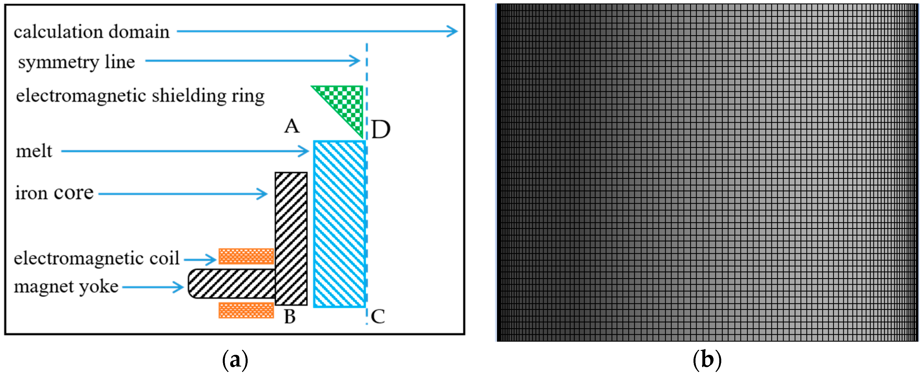
2.1. Physical Model
2.2. Mathematical Model and Physical Properties
- The melt of the 7075 alloy is an incompressible fluid;
- All materials are isotropic in the model;
- The displacement current and joule heat are ignorable.
2.3. Finite-Element Model and Boundary Conditions
- A physical model was established using the UG 9.0 software (Siemens PLM Software, Plano, TX, USA).
- The physical model was imported into Ansoft Maxwell (15.0, ANSYS, Inc.) to obtain the magnetic-flux density B by calculating the electromagnetic field.
- Through the MHD module, B is imported as the source term into Ansoft Fluent (15.0, ANSYS, Inc.).
- The temperature and flow fields are meshed and simulated numerically by using Ansoft Fluent.
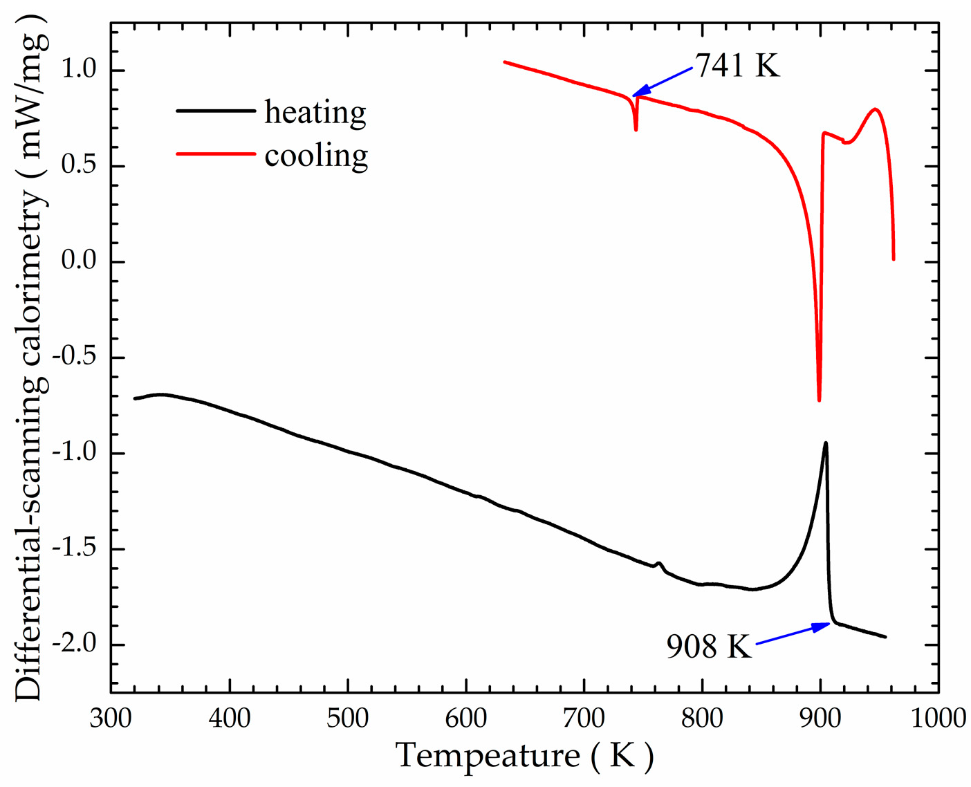
2.4. Experimental
3. Results
3.1. Electromagnetic Field Analysis
3.2. Thermal Field and Flow Field Analysis
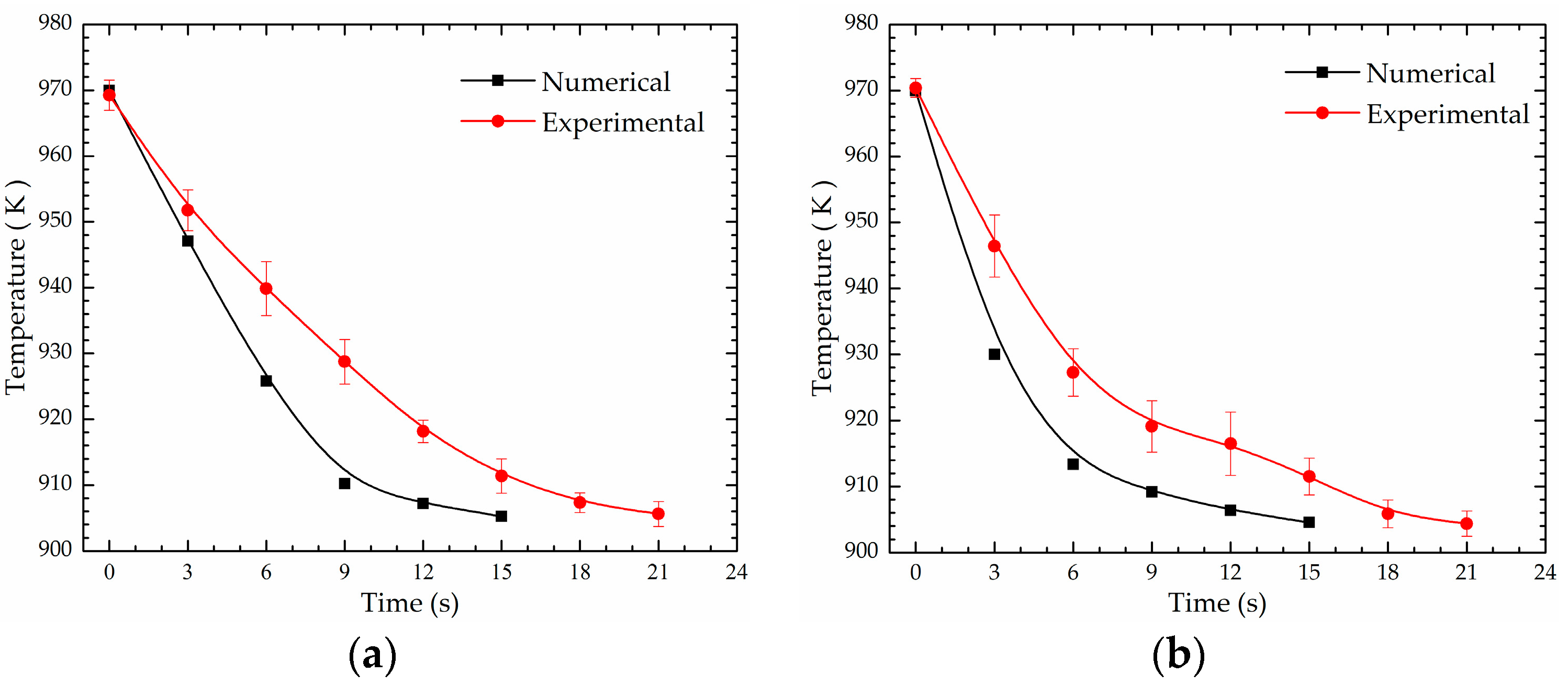
3.3. Experimental Validation
4. Discussion
5. Conclusions
- Compared with the ordinary AEMS process, electromagnetic shielding module reduces the magnetic flux density near the melt top, which ensures a more stable liquid surface; optimized electromagnetic generation module creates a higher magnetic flux density near the melt bottom, which exerts a higher shear rate and stronger stirring effects. The magnetic flux density near the melt top decreases from 8.2 to 3.7 mT, and the magnetic flux density near the melt bottom increases from 8.3 to 21.1 mT. The maximum velocity of the flow field increased from 1.51 to 14.31 m·s−1 for the M-AEMS. A uniform thermal field and a stable liquid surface can be achieved in a shorter time, and the temperature difference between the crucible wall and mandrel wall is 1.5 K after 21 s of melt treatment when the temperature of 7075 alloy melt drops from 970 to 907.5 K.
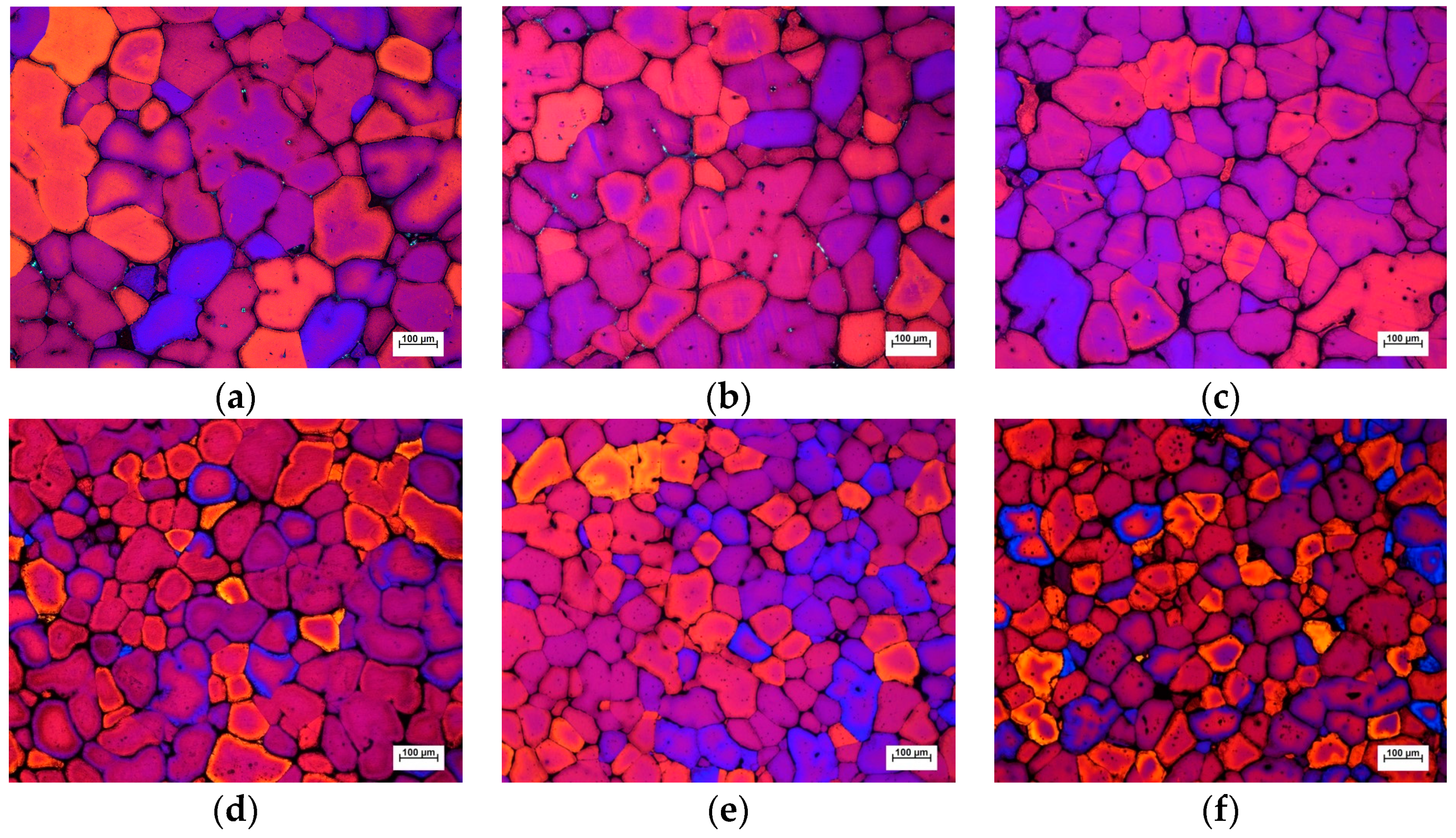
- By the M-AEMS process, the microstructure of the disk castings becomes more uniform and finer. The average grain size in the radial direction of the casting with pouring temperature of 910, 920, 930 and 940 K was reduced from 127, 144, 171 and 187 microns, respectively, to 115, 131, 152 and 174 microns. In addition, the chemical composition is distributed homogeneously, the relative segregation degree of the main alloying elements of Zn, Mg and Cu were reduced from 4.4%, 5.9% and 7.5%, respectively, to 2.1%, 3.3% and 4.2%. Both finer microstructure and more uniform composition distribution of the castings were obtained at the pouring temperatures of 910, 920, 930 and 940 K, indicating that the M-AEMS process has a wide process window to pouring temperature.
- The parameters of thermodynamic boundary conditions and indirectly coupled calculation have a great influence on the gap between numerical and experimental results. Thus, further research work should be done to realize directly coupled calculation of the electromagnetic field, thermal field and flow field for obtaining a precise prediction.
Author Contributions
Funding
Acknowledgments
Conflicts of Interest
References
- Fan, Z.; Fang, X.; Ji, S. Microstructure and mechanical properties of rheo-diecast (RDC) aluminium alloys. Mater. Sci. Eng. A 2005, 412, 298–306. [Google Scholar] [CrossRef]
- Fang, X.; Fan, Z. Rheo-diecasting of Al–Si–Pb immiscible alloys. Scr. Mater. 2006, 54, 789–793. [Google Scholar] [CrossRef]
- Findon, M. Semi-Solid Slurry Formation via Liquid Metal Mixing; Worcester Polytechnic Institute: Worcester, MA, USA, 2003. [Google Scholar]
- Doutre, D.; Langlais, J.; Roy, S. The SEED process for semi-solid forming. In Proceedings of the 8th International Conference on Semisolid Processing of Alloys and Composites, Limassol, Cyprus, 21–23 September 2004. [Google Scholar]
- Jian, X.; Meek, T.T.; Han, Q. Refinement of eutectic silicon phase of aluminum A356 alloy using high-intensity ultrasonic vibration. Scr. Mater. 2006, 54, 893–896. [Google Scholar] [CrossRef]
- Jian, X.; Xu, H.; Meek, T.T.; Han, Q. Effect of power ultrasound on solidification of aluminum A356 alloy. Mater. Lett. 2005, 59, 190–193. [Google Scholar] [CrossRef]
- Naji Meidani, A.R.; Hasan, M. A study of hydrogen bubble growth during ultrasonic degassing of Al–Cu alloy melts. J. Mater. Process. Technol. 2004, 147, 311–320. [Google Scholar] [CrossRef]
- Wang, K.; Peng, H.; Wang, N.; Wang, S. Method and Apparatus for Injection Molding of Semi-Solid Metals. U.S. Patent 5,501,266, 26 March 1996. [Google Scholar]
- Vives, C. Electromagnetic refining of aluminum alloys by the CREM process Part 1. Working principle and metallurgical results. Metall. Trans. B 1989, 20, 623–629. [Google Scholar] [CrossRef]
- Meyer, J.L. Method of Producing Thixotropic Metallic Products by Continuous Casting, with Polyphase Current Electromagnetic Agitation. U.S. Patent 5,219,018, 15 June 1993. [Google Scholar]
- Hirt, G.; Zillgen, M.; Gremer, R. Recent advances in thixoforming to produce near net shape components. In Proceedings of the First China International Die Casting Congress, Beijing, China, 14–17 April 1997; pp. 259–266. [Google Scholar]
- Midson, S.P. The commercial status of semi-solid casting in the USA. In Proceedings of the 4th International Conference on Semisolid Processing of Alloys and Composites, Sheffield, UK, 19–21 June 1996; pp. 21–29. [Google Scholar]
- Zhang, B.; Cui, J.; Lu, G. Effect of low-frequency magnetic field on macrosegregation of continuous casting aluminum alloys. Mater. Lett. 2003, 57, 1707–1711. [Google Scholar] [CrossRef]
- Kang, C.G.; Bae, J.W.; Kim, B.M. The grain size control of A356 aluminum alloy by horizontal electromagnetic stirring for rheology forging. J. Mater. Process. Technol. 2007, 187–188, 344–348. [Google Scholar] [CrossRef]
- Gao, Z.; Xu, J.; Zhang, Z.; Tang, M. Effect of annular electromagnetic stirring on microstructure and mechanical property of 7075 aluminium alloy. In Proceedings of the Chinese Materials Conference 2012, Shanxi, China, 13–18 July 2012. [Google Scholar]
- Park, S.Y.; Kim, W.J. Difference in the Hot Compressive Behavior and Processing Maps between the As-cast and Homogenized Al-Zn-Mg-Cu (7075) Alloys. J. Mater. Sci. Technol. 2016, 32, 660–670. [Google Scholar] [CrossRef]
- Zhang, B.; Cui, J.; Lu, G. Effects of low-frequency electromagnetic field on microstructures and macrosegregation of continuous casting 7075 aluminum alloy. Mater. Sci. Eng. A 2003, 355, 325–330. [Google Scholar] [CrossRef]
- Spitzer, K.H. Application of rotating magnetic fields in Czochralski crystal growth. Prog. Cryst. Growth Charact. Mater. 1999, 38, 59–71. [Google Scholar] [CrossRef]
- Mapelli, C.; Gruttadauria, A.; Peroni, M. Application of electromagnetic stirring for the homogenization of aluminium billet cast in a semi-continuous machine. J. Mater. Process. Technol. 2010, 210, 306–314. [Google Scholar] [CrossRef]
- Grants, I. Linear three-dimensional instability of a magnetically driven rotating flow. J. Fluid Mech. 2002, 463, 229–239. [Google Scholar] [CrossRef]
- Zhang, Q.; Cui, J.; Lu, G.; Zhang, B. Experimental investigation on surface meniscus shape under effect of electromagnetic field with low frequency of 7075 aluminum alloy produced by CREM process. Trans. Nonferrous Met. Soc. China 2002, 12, 109–111. [Google Scholar]
- Standard Test Methods for Determining Average Grain Size; American Society for Testing Materials: West Cornshooken, PA, USA, 2013.
- Hunt, J.D. Steady state columnar and equiaxed growth of dendrites and eutectic. Mater. Sci. Eng. 1984, 65, 75–83. [Google Scholar] [CrossRef]
- Jin, W.; Bai, F.; Li, T.; Yin, G. Grain refinement of superalloy IN100 under the action of rotary magnetic fields and inoculants. Mater. Lett. 2008, 62, 1585–1588. [Google Scholar] [CrossRef]


| Boundary Conditions | Type | Heat Transfer Coefficient (W/m2·K) | Free Stream Temperature (K) | Heat Generation Rate (W/m3) | |
|---|---|---|---|---|---|
| AB | Convection | 20 | 300 | 0 | |
| BC | Adiabatic | – | – | 0 | |
| CD | Convection | AEMS | 20 | 300 | 0 |
| M-AEMS | 2000 | 300 | 0 | ||
| DA | Convection | 20 | 300 | 0 | |
| Zn | Mg | Cu | Cr | Fe | Si | Ti | Mn | Other Each Element | Al |
|---|---|---|---|---|---|---|---|---|---|
| 5.63 | 2.41 | 1.57 | 0.15 | 0.19 | 0.36 | 0.14 | 0.27 | <0.05 | Balance |
© 2019 by the authors. Licensee MDPI, Basel, Switzerland. This article is an open access article distributed under the terms and conditions of the Creative Commons Attribution (CC BY) license (http://creativecommons.org/licenses/by/4.0/).
Share and Cite
He, M.; Zhang, Z.; Mao, W.; Li, B.; Bai, Y.; Xu, J. Numerical and Experimental Study on Melt Treatment for Large-Volume 7075 Alloy by a Modified Annular Electromagnetic Stirring. Materials 2019, 12, 820. https://doi.org/10.3390/ma12050820
He M, Zhang Z, Mao W, Li B, Bai Y, Xu J. Numerical and Experimental Study on Melt Treatment for Large-Volume 7075 Alloy by a Modified Annular Electromagnetic Stirring. Materials. 2019; 12(5):820. https://doi.org/10.3390/ma12050820
Chicago/Turabian StyleHe, Min, Zhifeng Zhang, Weimin Mao, Bao Li, Yuelong Bai, and Jun Xu. 2019. "Numerical and Experimental Study on Melt Treatment for Large-Volume 7075 Alloy by a Modified Annular Electromagnetic Stirring" Materials 12, no. 5: 820. https://doi.org/10.3390/ma12050820