Effects of CO2 Curing on Alkali-Activated Slag Paste Cured in Different Curing Conditions


Abstract
:1. Introduction
2. Experiments
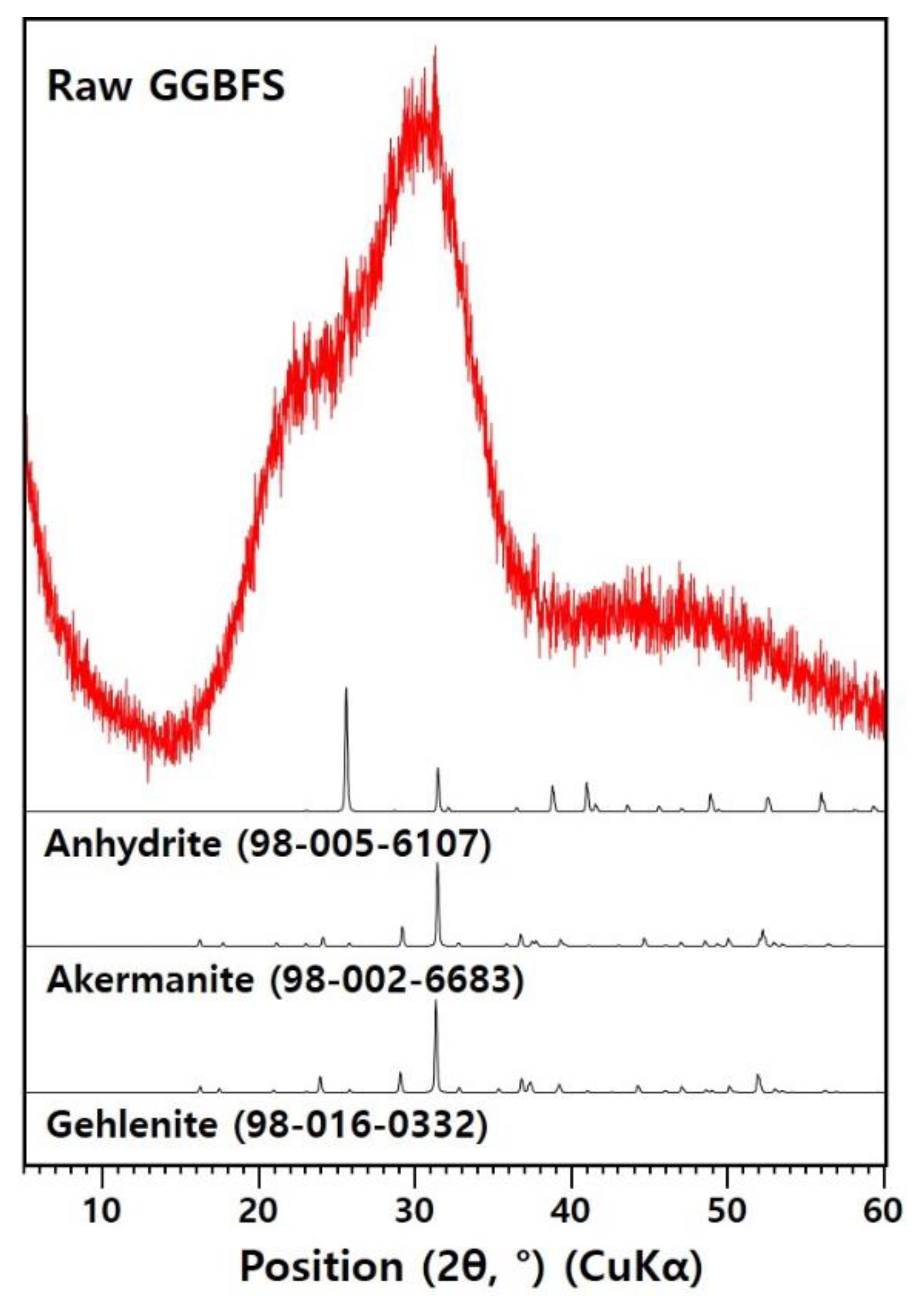
2.1. Materials
2.2. Experimental Design and Sample Preparations
3. Results and Discussion
4. Conclusions
Author Contributions
Funding
Conflicts of Interest
References
- Olivier, J.G.J.; Peters, J.A.H.W.; Schure, K.M. Trends in Global CO2 and Total Greenhouse Gas Emissions: 2018 Report; PBL Netherlands Environmental Assessment Agency: The Hague, The Netherlands, 2018. [Google Scholar]
- He, P.; Shi, C.; Tu, Z.; Poon, C.S.; Zhang, J. Effect of further water curing on compressive strength and microstructure of CO2-cured concrete. Cem. Concr. Compos. 2016, 72, 80–88. [Google Scholar] [CrossRef]
- Tu, Z.; Guo, M.-Z.; Poon, C.S.; Shi, C. Effects of limestone powder on CaCO3 precipitation in CO2 cured cement pastes. Cem. Concr. Compos. 2016, 72, 9–16. [Google Scholar] [CrossRef]
- Klemm, W.A.; Berger, R.L. Accelerated curing of cementitious systems by carbon dioxide: Part I. Portland cement. Cem. Concr. Res. 1972, 2, 567–576. [Google Scholar] [CrossRef]
- Young, J.F.; Berger, R.L.; Breese, J. Accelerated Curing of Compacted Calcium Silicate Mortars on Exposure to CO2. J. Am. Ceram. Soc. 1974, 57, 394–397. [Google Scholar] [CrossRef]
- Juenger, M.C.G.; Winnefeld, F.; Provis, J.L.; Ideker, J.H. Advances in alternative cementitious binders. Cem. Concr. Res. 2011, 41, 1232–1243. [Google Scholar] [CrossRef]
- Jun, Y.; Kim, H.J.; Kim, T. Hydration of Calcium Sulfoaluminate-Based Binder Incorporating Red Mud and Silica Fume. Appl. Sci. 2019, 9, 2270. [Google Scholar] [CrossRef]
- Palomo, A.; Grutzeck, M.W.; Blanco, M.T. Alkali-activated fly ashes: A cement for the future. Cem. Concr. Res. 1999, 29, 1323–1329. [Google Scholar] [CrossRef]
- Shi, C.; Jiménez, A.F.; Palomo, A. New cements for the 21st century: The pursuit of an alternative to Portland cement. Cem. Concr. Res. 2011, 41, 750–763. [Google Scholar] [CrossRef]
- Van Deventer, J.S.J.; Provis, J.L.; Duxson, P. Technical and commercial progress in the adoption of geopolymer cement. Miner. Eng. 2012, 29, 89–104. [Google Scholar] [CrossRef]
- Van Jaarsveld, J.G.S.; Van Deventer, J.S.J.; Lorenzen, L. The potential use of geopolymeric materials to immobilise toxic metals: Part I. Theory and applications. Miner. Eng. 1997, 10, 659–669. [Google Scholar] [CrossRef]
- Li, C.; Sun, H.; Li, L. A review: The comparison between alkali-activated slag (Si+Ca) and metakaolin (Si+Al) cements. Cem. Concr. Res. 2010, 40, 1341–1349. [Google Scholar] [CrossRef]
- Wang, S.-D.; Scrivener, K.L. Hydration products of alkali activated slag cement. Cem. Concr. Res. 1995, 25, 561–571. [Google Scholar] [CrossRef]
- Liu, H.; Lu, H.; Chen, D.; Wang, H.; Xu, H.; Zhang, R. Preparation and properties of glass–ceramics derived from blast-furnace slag by a ceramic-sintering process. Ceram. Int. 2009, 35, 3181–3184. [Google Scholar] [CrossRef]
- Park, S.M.; Jang, J.G.; Lee, N.K.; Lee, H.K. Physicochemical properties of binder gel in alkali-activated fly ash/slag exposed to high temperatures. Cem. Concr. Res. 2016, 89, 72–79. [Google Scholar] [CrossRef]
- Jun, Y.; Yoon, S.; Oh, E.J. A Comparison Study for Chloride-Binding Capacity between Alkali-Activated Fly Ash and Slag in the Use of Seawater. Appl. Sci. 2017, 7, 971. [Google Scholar] [CrossRef]
- Data ICDD. PDF-2 Database; Data ICDD: Newton Square, PA, USA, 2000. [Google Scholar]
- Allmann, R.; Hinek, R. The introduction of structrue types into the inorganic crystal structure database ICSD. Acta Crystallogr. A 2007, 63, 412–417. [Google Scholar] [CrossRef]
- Monkman, S.; Shao, Y. Assessing the Carbonation Behavior of Cementitious Materials. J. Mater. Civ. Eng. 2006, 18, 768–776. [Google Scholar] [CrossRef]
- Rostami, V.; Shao, Y.; Boyd, A.J.; He, Z. Microstructure of cement paste subject to early carbonation curing. Cem. Concr. Res. 2012, 42, 186–193. [Google Scholar] [CrossRef]
- Xuan, D.; Zhan, B.; Poon, C.S. A maturity approach to estimate compressive strength development of CO2-cured concrete blocks. Cem. Concr. Compos. 2018, 85, 153–160. [Google Scholar] [CrossRef]
- Sakulich, A.R.; Anderson, E.; Schauer, C.; Barsoum, M.W. Mechanical and microstructural characterization of an alkali-activated slag/limestone fine aggregate concrete. Constr. Build. Mater. 2009, 23, 2951–2957. [Google Scholar] [CrossRef]
- Puertas, F.; Palacios, M.; Manzano, H.; Dolado, J.S.; Rico, A.; Rodríguez, J. A model for the C-A-S-H gel formed in alkali-activated slag cements. J. Eur. Ceram. Soc. 2011, 31, 2043–2056. [Google Scholar] [CrossRef]
- Richardson, I.G.; Brough, A.R.; Groves, G.W.; Dobson, C.M. The characterization of hardened alkali-activated blast-furnace slag pastes and the nature of the calcium silicate hydrate (C-S-H) phase. Cem. Concr. Res. 1994, 24, 813–829. [Google Scholar] [CrossRef]
- Chang, R.; Choi, D.; Kim, M.H.; Park, Y. Tuning Crystal Polymorphisms and Structural Investigation of Precipitated Calcium Carbonates for CO2 Mineralization. ACS Sustain. Chem. Eng. 2017, 5, 1659–1667. [Google Scholar] [CrossRef]
- Kato, T. Polymer/Calcium carbonate layered thin-film composites. Adv. Mater. 2000, 12, 1543–1546. [Google Scholar] [CrossRef]
- Qiao, L.; Feng, Q.L.; Liu, Y. A novel bio-vaterite in freshwater pearls with high thermal stability and low dissolubility. Mater. Lett. 2008, 62, 1793–1796. [Google Scholar] [CrossRef]
- Ben Haha, M.; Le Saout, G.; Winnefeld, F.; Lothenbach, B. Influence of activator type on hydration kinetics, hydrate assemblage and microstructural development of alkali activated blast-furnace slags. Cem. Concr. Res. 2011, 41, 301–310. [Google Scholar] [CrossRef]
- Jeon, D.; Jun, Y.; Jeong, Y.; Oh, J.E. Microstructural and strength improvements through the use of Na2CO3 in a cementless Ca(OH)2-activated Class F fly ash system. Cem. Concr. Res. 2015, 67, 215–225. [Google Scholar] [CrossRef]
- Wang, K.; Shah, S.P.; Mishulovich, A. Effects of curing temperature and NaOH addition on hydration and strength development of clinker-free CKD-fly ash binders. Cem. Concr. Res. 2004, 34, 299–309. [Google Scholar] [CrossRef]
- Palacios, M.; Puertas, F. Effect of Carbonation on Alkali-Activated Slag Paste. J. Am. Ceram. Soc. 2006, 89, 3211–3221. [Google Scholar] [CrossRef]
- El-Didamony, H.; Amer, A.A.; Abd Ela-ziz, H. Properties and durability of alkali-activated slag pastes immersed in sea water. Ceram. Int. 2012, 38, 3773–3780. [Google Scholar] [CrossRef]
- Ashraf, W.; Olek, J. Carbonation activated binders from pure calcium silicates: Reaction kinetics and performance controlling factors. Cem. Concr. Compos. 2018, 93, 85–98. [Google Scholar] [CrossRef]
- Shi, C.; He, F.; Wu, Y. Effect of pre-conditioning on CO2 curing of lightweight concrete blocks mixtures. Constr. Build. Mater. 2012, 26, 257–267. [Google Scholar] [CrossRef]
- Shi, C.; Wu, Y. Studies on some factors affecting CO2 curing of lightweight concrete products. Resour. Conserv. Recycl. 2008, 52, 1087–1092. [Google Scholar] [CrossRef]
- Kojima, Y.; Kanai, M.; Nishimiya, N. Synthesis of novel amorphous calcium carbonate by sono atomization for reactive mixing. Ultrason. Sonochem. 2012, 19, 325–329. [Google Scholar] [CrossRef] [PubMed]
- Nedeljković, M.; Ghiassi, B.; Melzer, S.; Kooij, C.; van der Laan, S.; Ye, G. CO2 binding capacity of alkali-activated fly ash and slag pastes. Ceram. Int. 2018, 44, 19646–19660. [Google Scholar] [CrossRef]


| CaO | SiO2 | Al2O3 | Na2O | K2O | MgO | MnO | TiO2 | SO3 | P2O5 | Fe2O3 | Others |
|---|---|---|---|---|---|---|---|---|---|---|---|
| 47.97 | 30.76 | 13.26 | 0.23 | 0.54 | 3.06 | 0.52 | 0.87 | 1.81 | 0.01 | 0.61 | 0.25 |
| Binder (g) | Activator (g) | Activator/Binder | |
|---|---|---|---|
| GGBFS | 5M NaOH | Liquid Na2SiO3 | |
| 2400 | 480 | 480 | 0.4 |
| Sample Label | Curing time | ||||
|---|---|---|---|---|---|
| 1 h | 3 h | 20 h | 6 Days | 35 Days | |
| Control | Chamber at 25 °C and 85% RH | Chamber at 25 °C and 85% RH | |||
| CO2P-T1 | 3-bar CO2 pressure vessel | Chamber at 25 °C and 85% RH | |||
| CO2P-T2 | 3-bar CO2 pressure vessel | Chamber at 25 °C and 85% RH | |||
| CO2P-T3 | 3-bar CO2 pressure vessel | Chamber at 25 °C and 85% RH | |||
| CO2-HC | 20%-concentration CO2 chamber at 25 °C and 70% RH | ||||
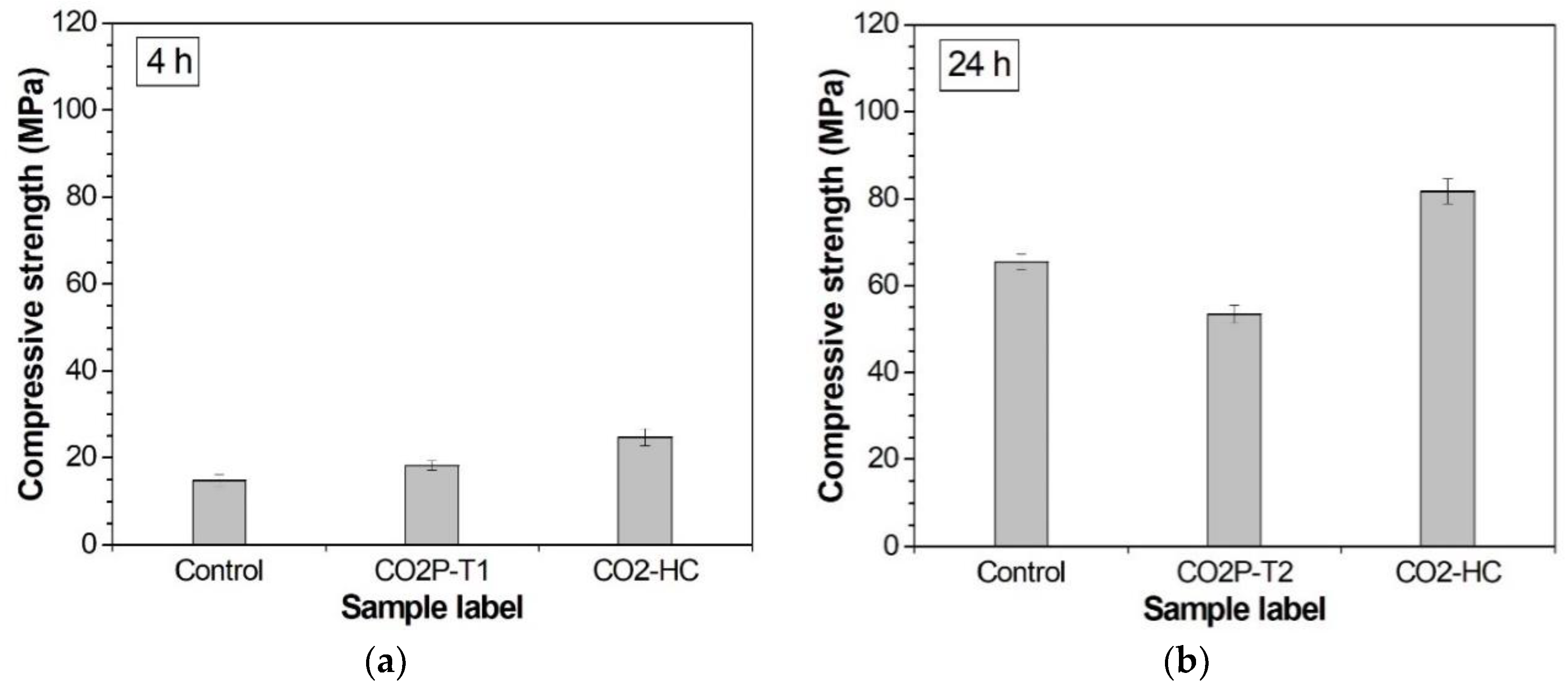
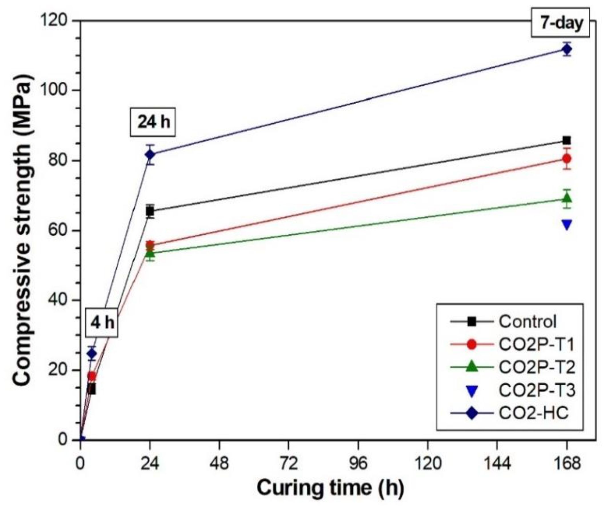
| Sample Label | Compressive Strength (Standard Deviation), MPa | |||
|---|---|---|---|---|
| 4 h | 24 h | 7 Days | 42 Days | |
| Control | 14.78 (1.33) | 65.56 (1.88) | 85.77 (0.88) | 108.83 (3.52) |
| CO2P-T1 | 18.27 (1.1) | 55.72 (1.14) | 80.62 (2.99) | 85.6 (1.62) |
| CO2P-T2 | - | 53.47 (2.09) | 69.11 (2.6) | 74.69 (1.9) |
| CO2P-T3 | - | - | 61.96 (0.48) | 73.87 (2.57) |
| CO2-HC | 24.81 (1.96) | 81.77 (2.86) | 111.89 (1.88) | 121.98 (1.43) |
| Sample Label | Calcite Concentration | ||
|---|---|---|---|
| 4 h | 24 h | 7 Days | |
| Control | 1.33% | 1.51% | 2.09% |
| CO2P-T1 | 1.43% | 2.90% | 4.07% |
| CO2P-T2 | - | 3.64% | 3.93% |
| CO2P-T3 | - | - | 2.76% |
| CO2-HC | 8.37% | 6.96% | 2.27% |
© 2019 by the authors. Licensee MDPI, Basel, Switzerland. This article is an open access article distributed under the terms and conditions of the Creative Commons Attribution (CC BY) license (http://creativecommons.org/licenses/by/4.0/).
Share and Cite
Jun, Y.; Han, S.H.; Shin, T.Y.; Kim, J.H. Effects of CO2 Curing on Alkali-Activated Slag Paste Cured in Different Curing Conditions. Materials 2019, 12, 3513. https://doi.org/10.3390/ma12213513
Jun Y, Han SH, Shin TY, Kim JH. Effects of CO2 Curing on Alkali-Activated Slag Paste Cured in Different Curing Conditions. Materials. 2019; 12(21):3513. https://doi.org/10.3390/ma12213513
Chicago/Turabian StyleJun, Yubin, Seong Ho Han, Tae Yong Shin, and Jae Hong Kim. 2019. "Effects of CO2 Curing on Alkali-Activated Slag Paste Cured in Different Curing Conditions" Materials 12, no. 21: 3513. https://doi.org/10.3390/ma12213513