Mechanical Properties and Microstructures of Laser–TIG Welded ME21 Rare Earth Mg Alloy


Abstract
:1. Introduction
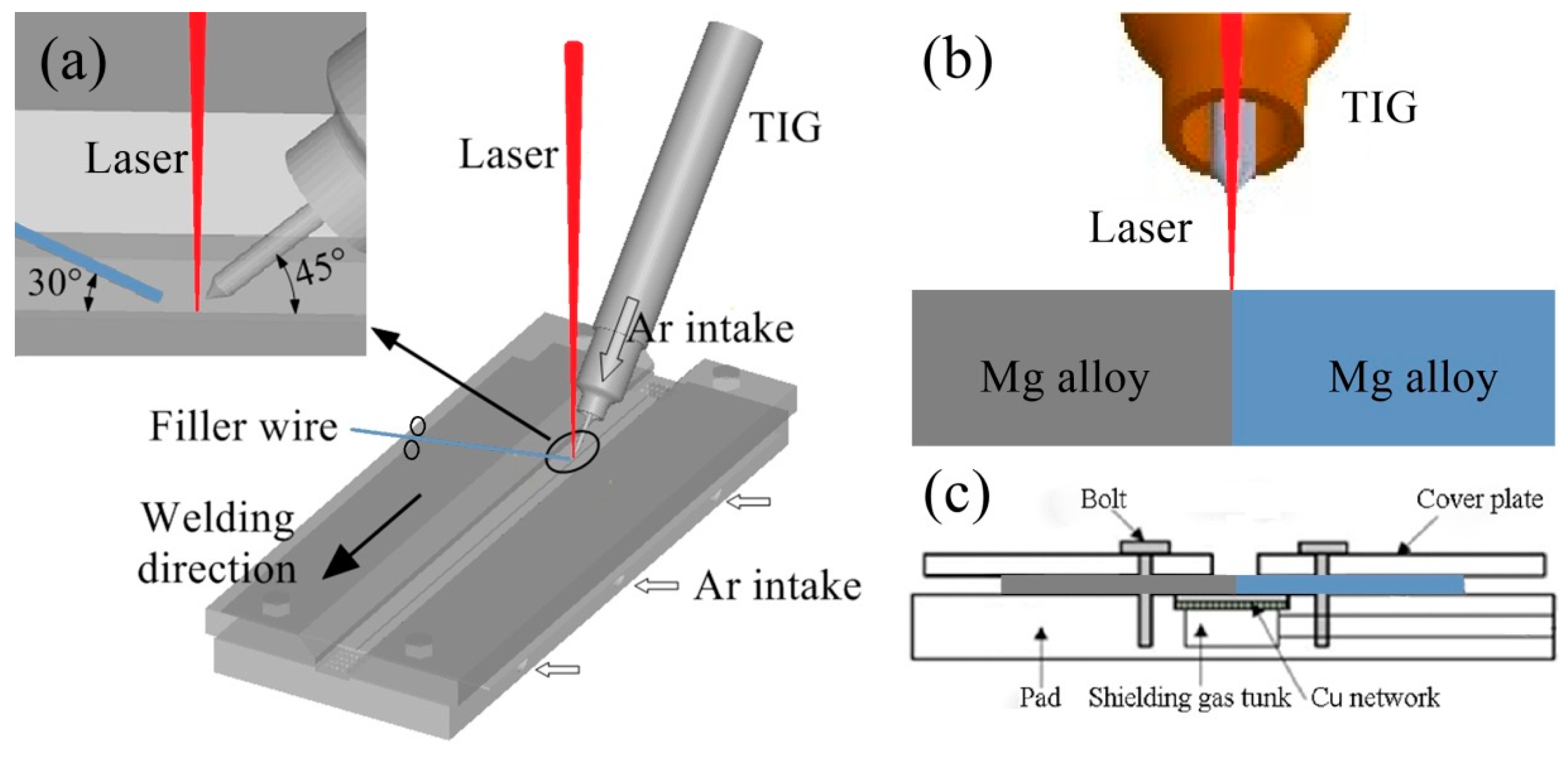
2. Experimental Procedures
3. Results and Discussion
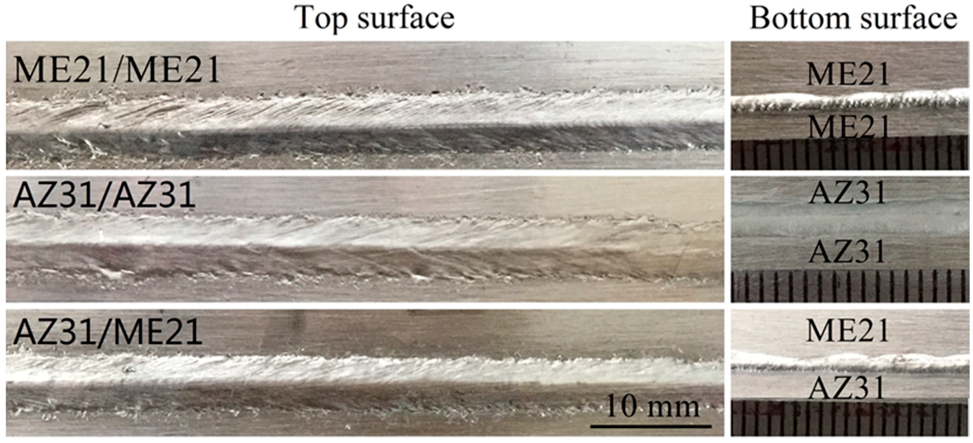
3.1. Bead Shape
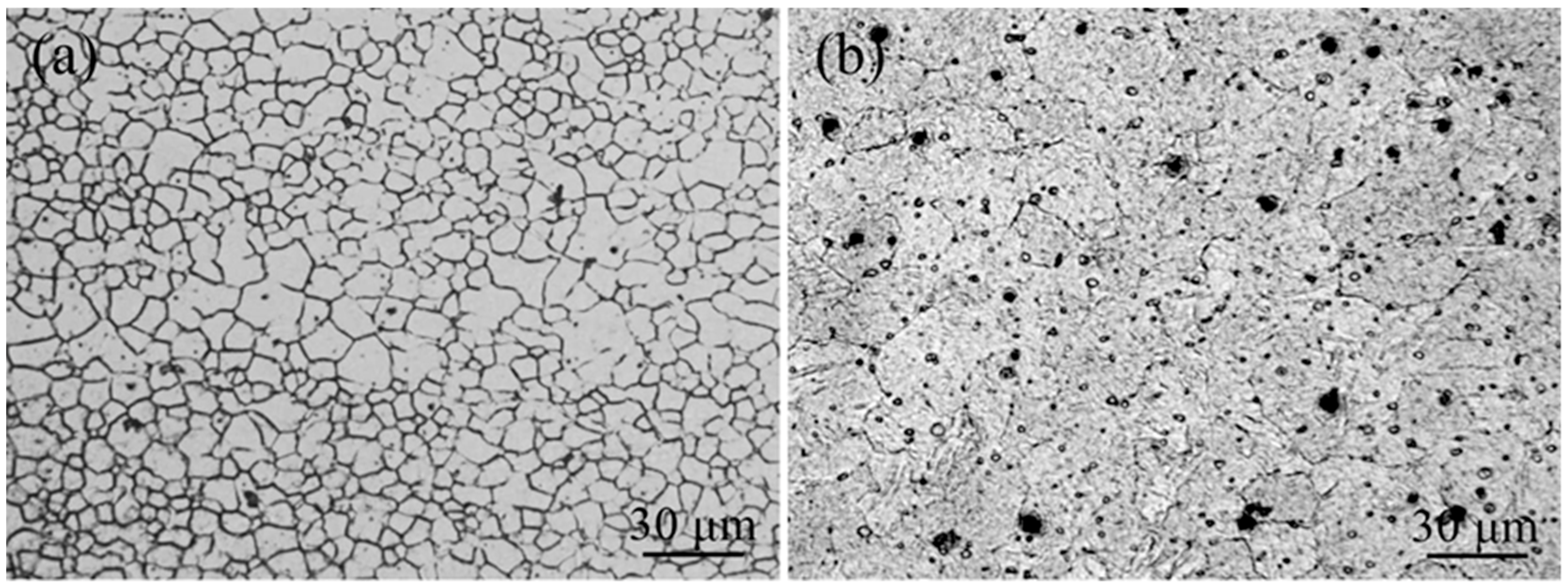
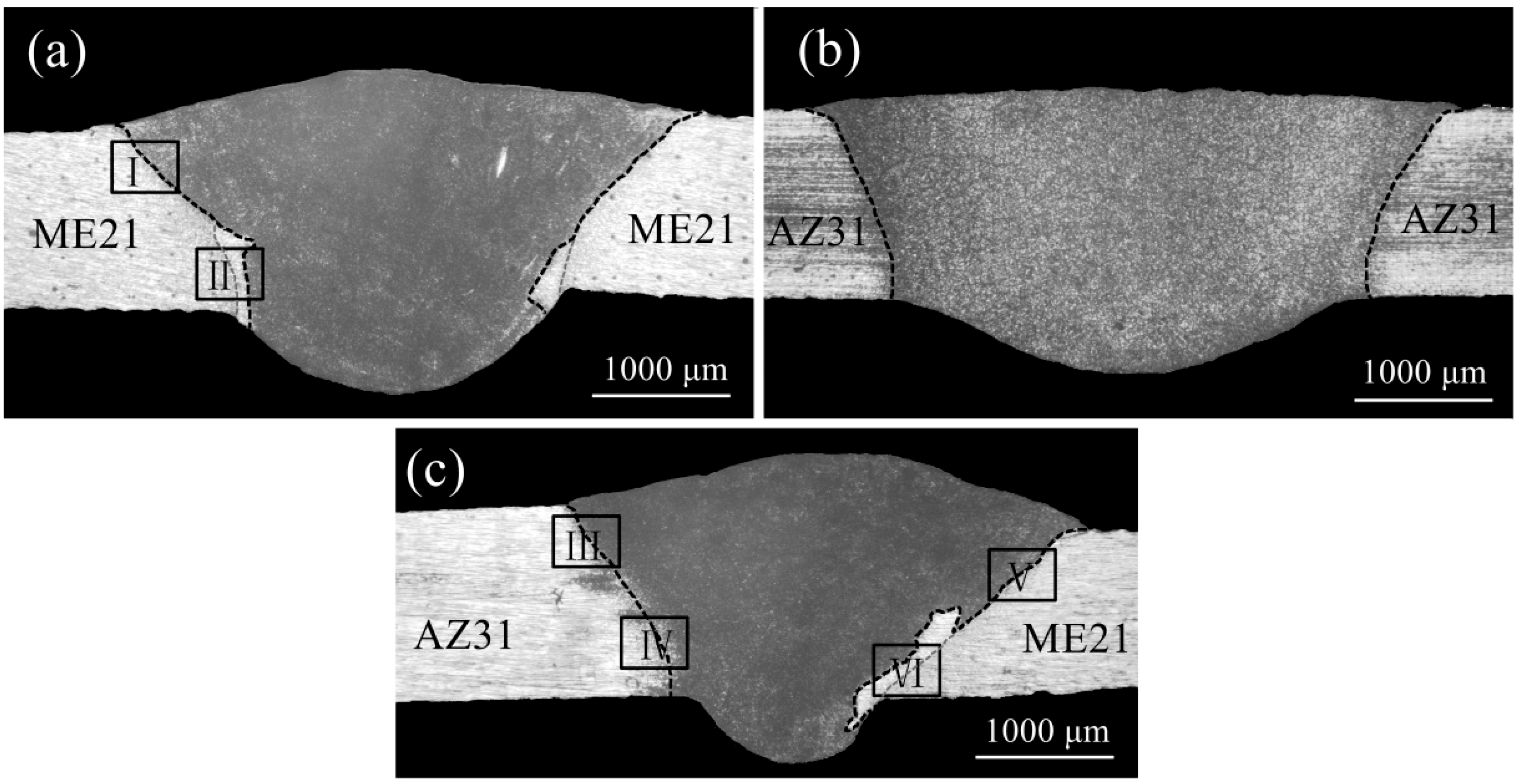
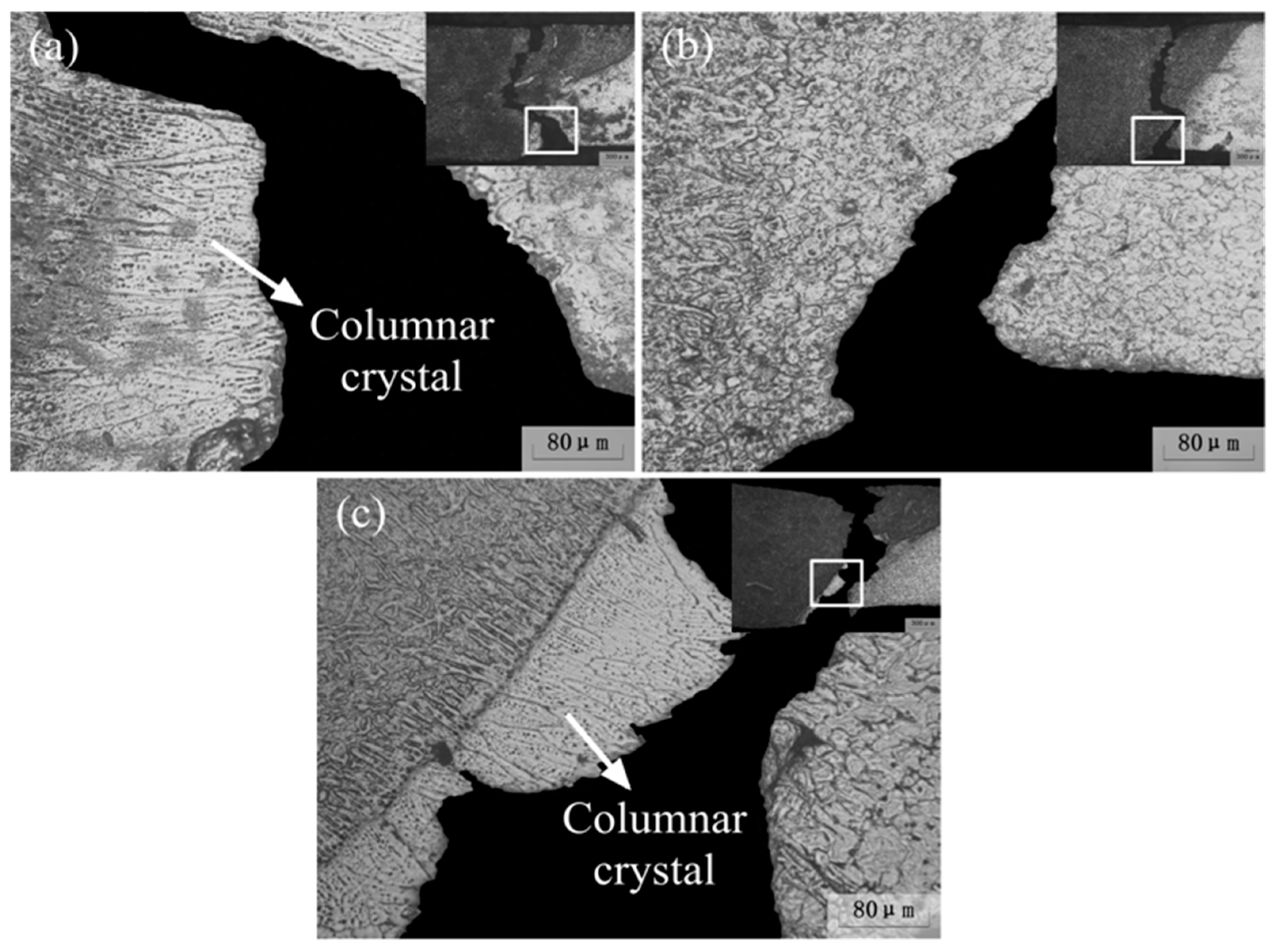
3.2. Microstructure Characteristics
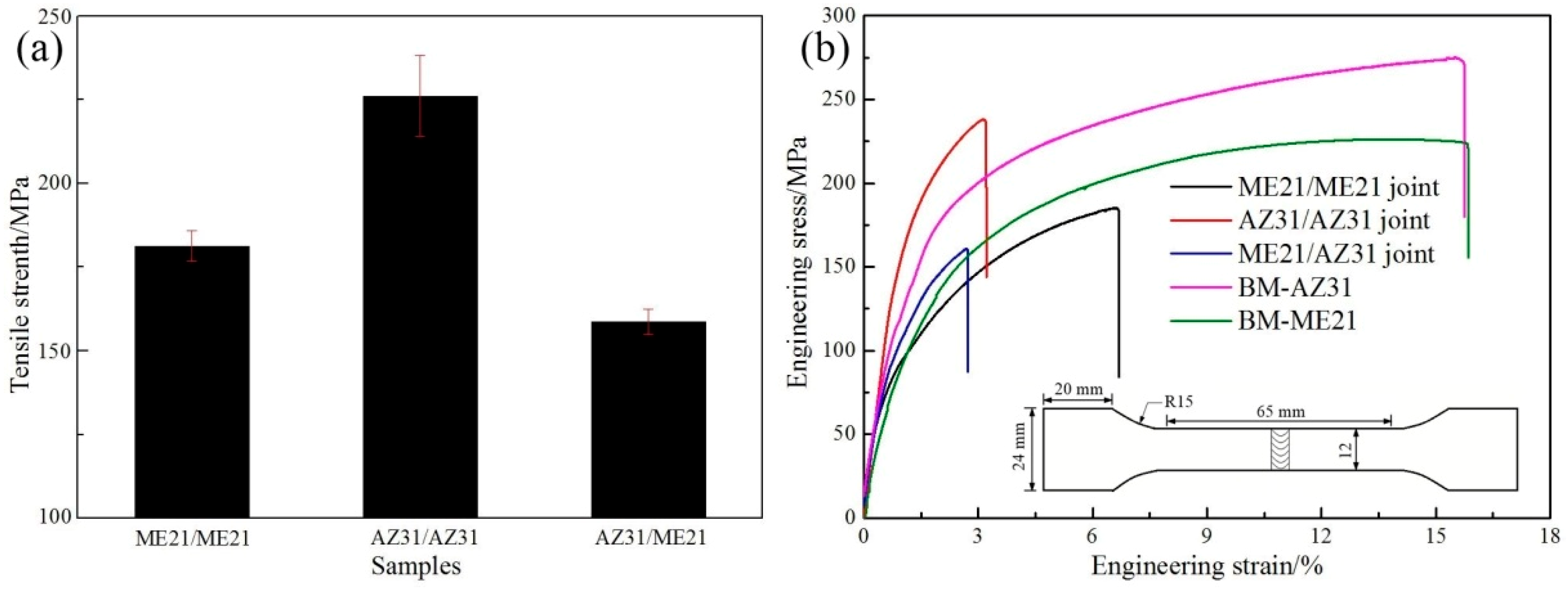
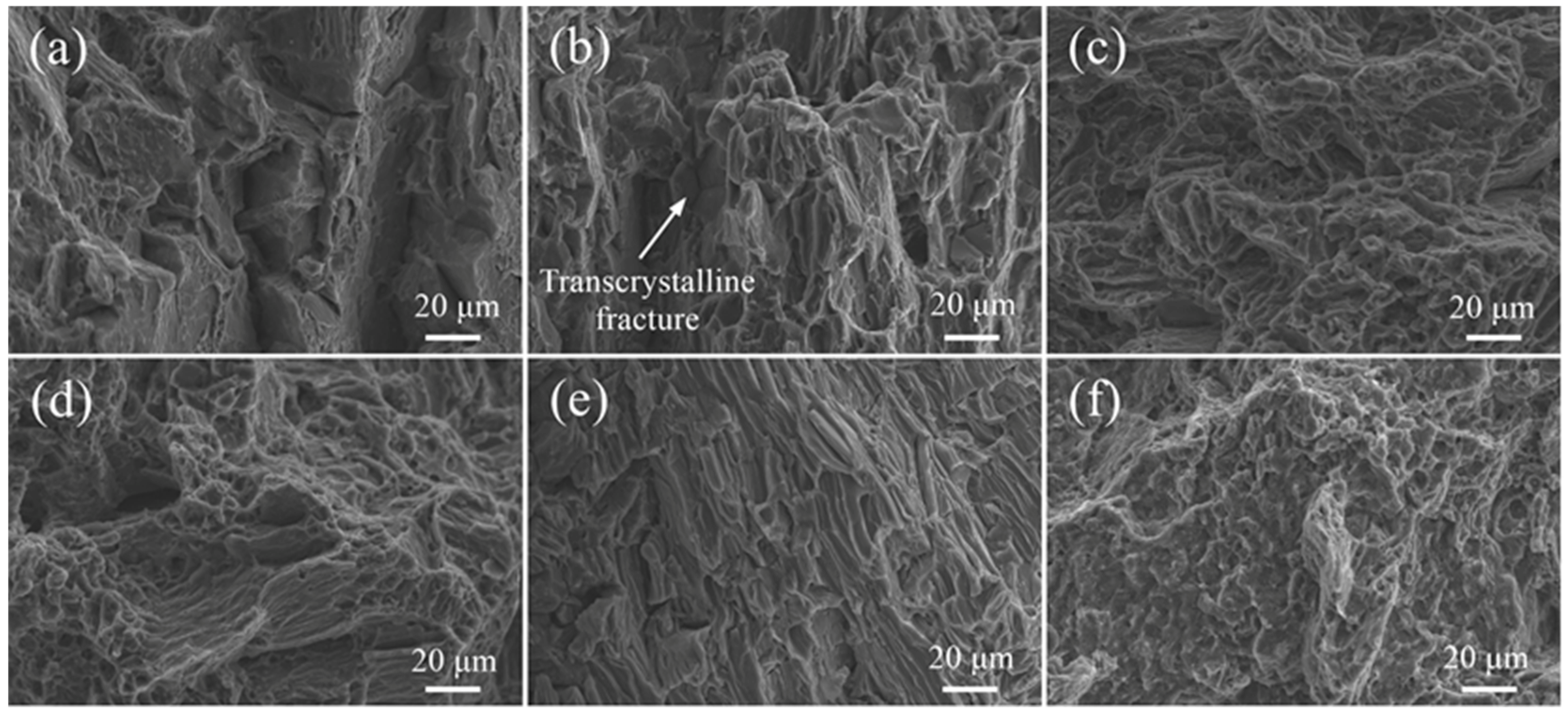
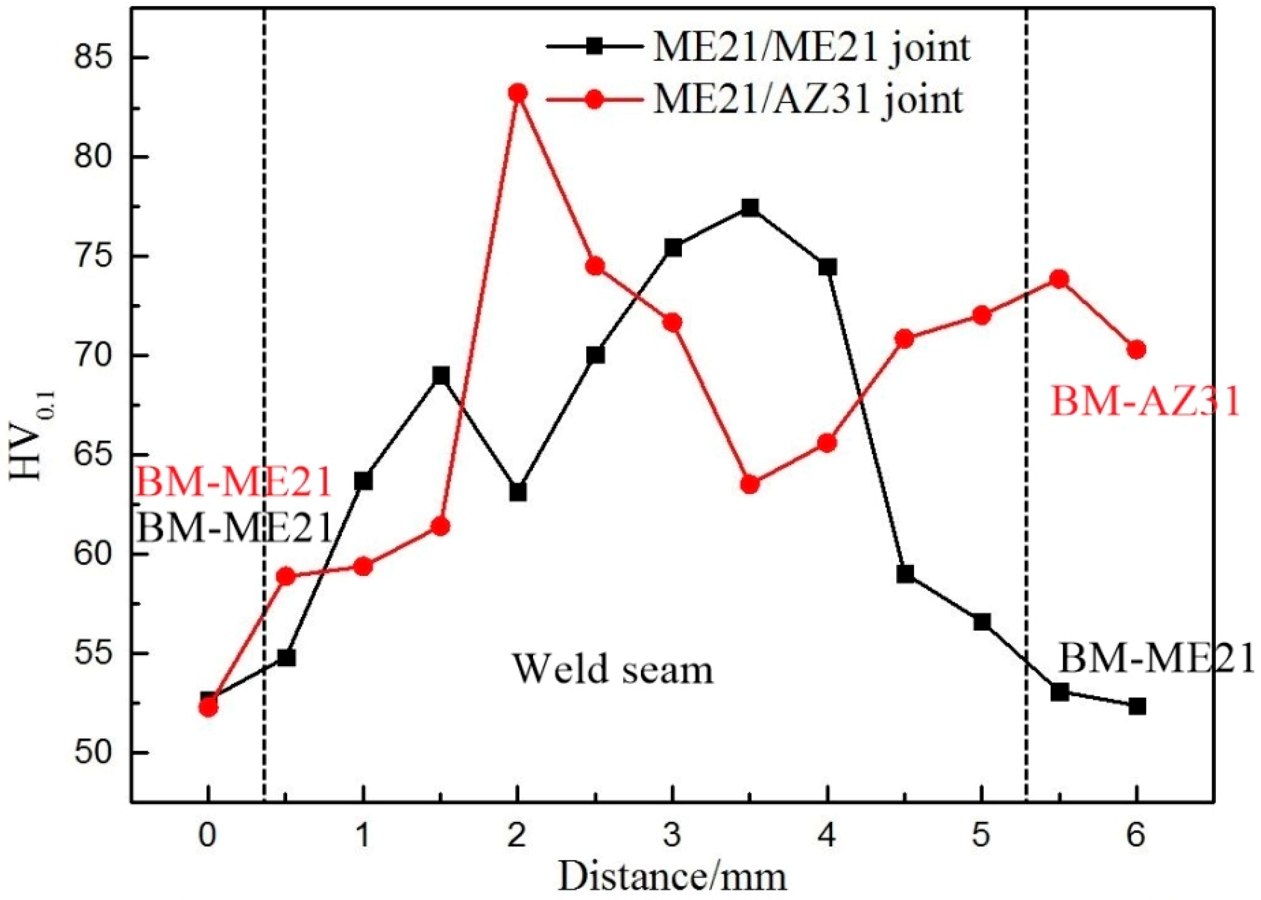
3.3. Mechanical Properties
4. Conclusions
- AZ31 and ME21, AZ31 and AZ31, and ME21 and ME21 Mg alloy sheets were successfully welded by laser–TIG hybrid welding with filler wire. The laser power, arc current, and welding speed were 500 W, 80 A, and 1900 mm/min, respectively. The welding heat input was 30.5 J/mm.
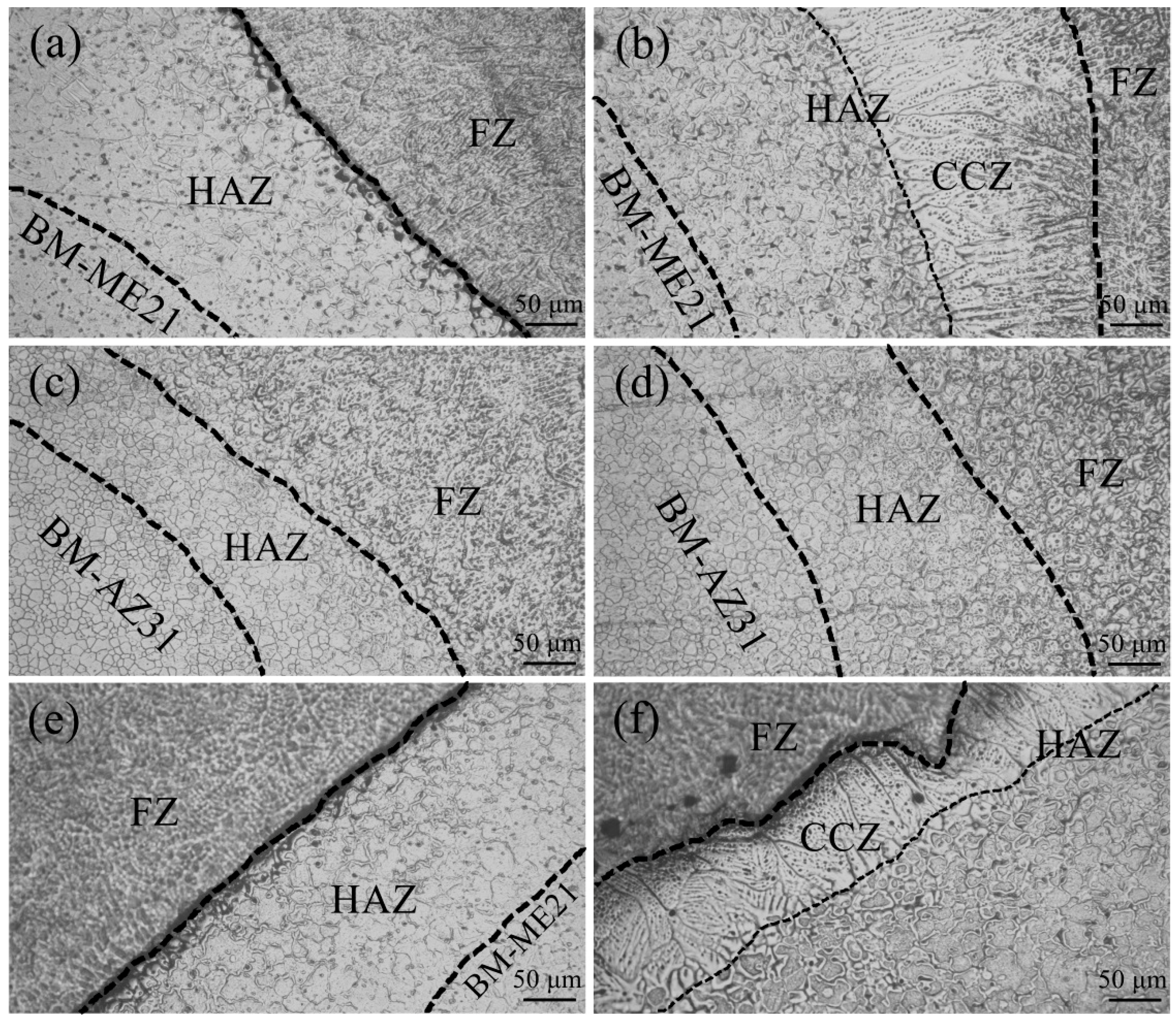
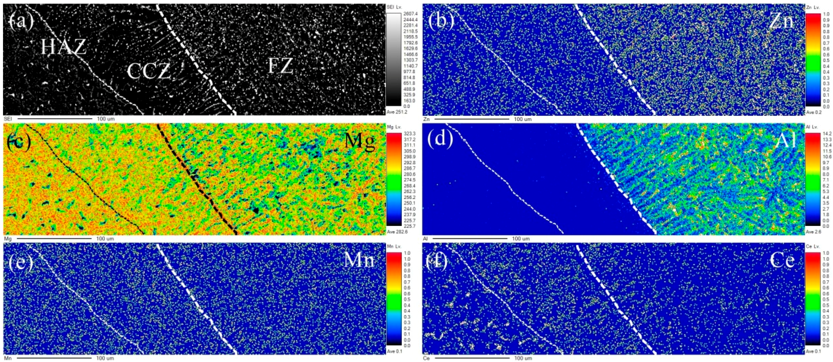
- Columnar crystals appeared in the ME21/ME21 and ME21/AZ31 FZ, which grew along the side wall of the HAZ, and no columnar crystals formed in the AZ31/AZ31 fusion zone at the same experimental conditions. The HAZ contains the CCZ.
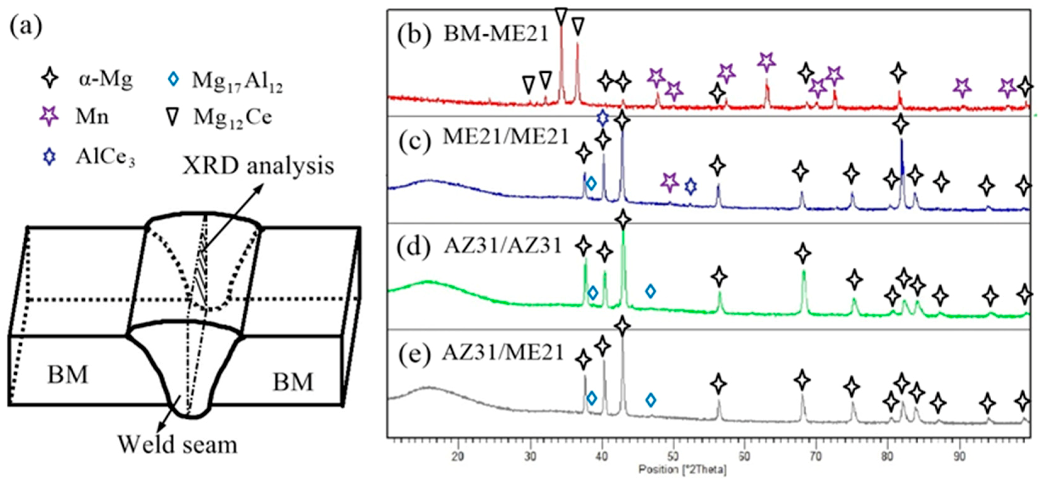
- The ME21/ME21 weld seam is composed of an AlCe3 intermetallic compound, Mn particles, and α-Mg, and the ME21/AZ31 weld seam is composed of a α-Mg, Mg17Al12, and AlCe3 intermetallic compound.
- The ME21/ME21 and ME21/AZ31 joints are broken at the junction of the columnar crystal and the heat-affected zone. The ME21/ME21 joint has a tensile strength of up to 185.2 MPa, which is about 81.8% of BM-ME21. The ME21/AZ31 joint (158.8 MPa) is lower than the tensile strength of the ME21/ME21 joint.
Author Contributions
Funding
Conflicts of Interest
References
- Yoon, J.; Lee, S. Warm forging of magnesium AZ80 alloy for the control arm in an automobile. Proc. Inst. Mech. Eng. Part D J. Automob. Eng. 2015, 229, 1732–1738. [Google Scholar] [CrossRef]
- Schieck, F.; Drossel, W.; Braeunlich, H.; Scheffler, S.; Pierschel, N. Temperature-Supported Forming of Automobile Related Magnesium Components. In Proceedings of the ASME 2013 International Mechanical Engineering Congress and Exposition, San Diego, CA, USA, 15–21 November 2013. [Google Scholar]
- Zhao, D.; Ren, D.; Zhao, K.; Pan, S.; Guo, X. Effect of welding parameters on tensile strength of ultrasonic spot welded joints of aluminum to steel—By experimentation and artificial neural network. J. Manuf. Process. 2017, 30, 63–74. [Google Scholar] [CrossRef]
- Zhao, H.; Yu, M.; Jiang, Z.; Zhou, L.; Song, X. Interfacial microstructure and mechanical properties of Al/Ti dissimilar joints fabricated via friction stir welding. J. Alloys Compd. 2019, 789, 139–149. [Google Scholar] [CrossRef]
- Zhou, L.; Li, G.H.; Zhang, R.X.; Zhou, W.L.; He, W.X.; Huang, Y.X.; Song, X.G. Microstructure evolution and mechanical properties of friction stir spot welded dissimilar aluminum-copper joint. J. Alloys Compd. 2019, 775, 372–382. [Google Scholar] [CrossRef]
- Zhou, P.; Beeh, E.; Friedrich, H.E.; Grunheid, T. Mechanical Behavior and Microstructural Analysis of Extruded AZ31B Magnesium Alloy Processed by Backward Extrusion. J. Mater. Eng. Perform. 2016, 25, 2866–2877. [Google Scholar] [CrossRef] [Green Version]
- Wang, J.; Liu, R.D.; Dong, X.G.; Yang, Y.S. Microstructure and mechanical properties of Mg-Zn-Y-Nd-Zr alloys. J. Rare Earths 2013, 31, 616–621. [Google Scholar] [CrossRef]
- Mirza, F.A.; Wang, K.; Bhole, S.D.; Friedman, J.; Chen, D.L.; Ni, D.R.; Xiao, B.L.; Ma, Z.Y. Strain-controlled low cycle fatigue properties of a rare-earth containing MEmagnesium alloy. Mater. Sci. Eng. A 2016, 661, 115–125. [Google Scholar] [CrossRef]
- Estrin, Y.; Nene, S.S.; Kashyap, B.P.; Prabhu, N.; Al-Samman, T. New hot rolled Mg-4Li-1Ca alloy: A potential candidate for automotive and biodegradable implant applications. Mater. Lett. 2016, 173, 252–256. [Google Scholar] [CrossRef]
- Shufen, W.; Wenwen, H.; Zhenhai, G.; Tianpeng, Z. The Application of Magnesium Alloy in Automotive Seat Design. Appl. Mech. Mater. 2013, 395–396, 266–270. [Google Scholar] [CrossRef]
- Dong, H.; Liao, C.; Yang, L. Microstructure and mechanical properties of AZ31B magnesium alloy gas metal arc weld. Trans. Nonferrous Met. Soc. China 2012, 22, 1336–1341. [Google Scholar] [CrossRef]
- Quan, Y.J.; Chen, Z.H.; Gong, X.S.; Yu, Z.H. Effects of heat input on microstructure and tensile properties of laser welded magnesium alloy AZ31. Mater. Charact. 2008, 59, 1491–1497. [Google Scholar] [CrossRef]
- Carlone, P.; Astarita, A.; Rubino, F.; Pasquino, N. Microstructural Aspects in FSW and TIG Welding of Cast ZE41A Magnesium Alloy. Metall. Mater. Trans. B 2016, 47, 1340–1346. [Google Scholar] [CrossRef]
- Bailey, N.S.; Tan, W.D.; Shin, Y.C. A Parametric Study on Laser Welding of Magnesium Alloy AZby a Fiber Laser. Trans. ASME J. Manuf. Sci. Eng. 2015, 137. [Google Scholar] [CrossRef]
- Gao, M.; Cao, Y.; Zeng, X.Y.; Lin, T.X. Mechanical properties and microstructures of hybrid laser MIG welded dissimilar Mg-Al-Zn alloys. Sci. Technol. Weld. Join. 2010, 15, 638–645. [Google Scholar] [CrossRef]
- Coelho, R.S.; Kostka, A.; Pinto, H.; Riekehr, S.; Kocak, M.; Pyzalla, A.R. Microstructure and mechanical properties of magnesium alloy AZ31B laser beam welds. Mat. Sci. Eng. A 2007, 485, 20–30. [Google Scholar] [CrossRef]
- Carlone, P.; Palazzo, G.S. Characterization of TIG and FSW weldings in cast ZE41A magnesium alloy. J. Mater. Process. Technol. 2015, 215, 87–94. [Google Scholar] [CrossRef]
- Liang, Y.; Shen, J.; Hu, S.; Wang, H.; Pang, J. Effect of TIG current on microstructural and mechanical properties of 6061-Taluminium alloy joints by TIG-CMT hybrid welding. J. Mater. Process. Technol. 2018, 255, 161–174. [Google Scholar] [CrossRef]
- Oliveira, J.; Barbosa, D.; Braz Fernandes, F.; Miranda, R.M. Tungsten inert gas (TIG) welding of Ni-rich NiTi plates: Functional behavior. Smart Mater. Struct. 2016, 25, 1L–3L. [Google Scholar] [CrossRef]
- Oliveira, J.P.; Schell, N.; Zhou, N.; Wood, L.; Benafan, O. Laser welding of precipitation strengthened Ni-rich NiTiHf high temperature shape memory alloys: Microstructure and mechanical properties. Mater. Des. 2019, 162, 229–234. [Google Scholar] [CrossRef]
- Razmpoosh, M.H.; Macwan, A.; Biro, E.; Chen, D.L.; Peng, Y.; Goodwin, F.; Zhou, Y. Liquid metal embrittlement in laser beam welding of Zn-coated 22MnBsteel. Mater. Des. 2018, 155, 375–383. [Google Scholar] [CrossRef]
- Cao, X.; Jahazi, M.; Immarigeon, J.P.; Wallace, W. A review of laser welding techniques for magnesium alloys. J. Mater. Process. Technol. 2006, 171, 188–204. [Google Scholar] [CrossRef]
- Zhang, L.J.; Zhang, G.F.; Ning, J.; Zhang, X.J.; Zhang, J.X. Microstructure and properties of the laser butt welded 1.5-mm thick Tcopper joint achieved at high welding speed. Mater. Des. 2015, 88, 720–736. [Google Scholar] [CrossRef]
- Hou, Z.L.; Li, C.B.; Liu, L.M. Laser-TIG Hybrid Welding of Magnesium Alloy T-Joint with Cold Filler Wire. Mater. Trans. 2015, 56, 1242–1247. [Google Scholar] [CrossRef] [Green Version]
- Song, G.; Luo, Z.M. The influence of laser pulse waveform on laser-TIG hybrid welding of AZ31B magnesium alloy. Opt. Laser Eng. 2011, 49, 82–88. [Google Scholar] [CrossRef]
- Li, C.B.; Chen, M.H.; Yuan, S.T.; Liu, L.M. Effect of Welding Speed in High Speed Laser-TIG Welding of Magnesium Alloy. Mater. Manuf. Process. 2012, 27, 1424–1428. [Google Scholar] [CrossRef]
- Song, G.; Yu, J.W.; Li, T.T.; Wang, J.F.; Liu, L.M. Effect of laser-GTAW hybrid welding heat input on the performance of Mg/Steel butt joint. J. Manuf. Process. 2018, 31, 131–138. [Google Scholar] [CrossRef]
- Zhong, L.; Peng, J.; Li, M.; Wang, Y.; Lu, Y.; Pan, F. Effect of Ce addition on the microstructure, thermal conductivity and mechanical properties of Mg-0.5Mn alloys. J. Alloys Compd. 2016, 661, 402–410. [Google Scholar] [CrossRef]
- Su, S.F.; Huang, J.C.; Lin, H.K.; Ho, N.J. Electron-beam welding behavior in Mg-Al-based alloys. Metall. Mater. Trans. A 2002, 33, 1461–1473. [Google Scholar] [CrossRef]
- Wang, C.; Chen, Y.; Xiao, S. Situation of Research and Development of Thermal Conductive Magnesium Alloys. Rare Met. Mater. Eng. 2015, 44, 2596–2600. [Google Scholar]
- Gao, M.; Mei, S.W.; Wang, Z.M.; Li, X.Y.; Zeng, X.Y. Process and joint characterizations of laser-MIG hybrid welding of AZmagnesium alloy. J. Mater. Process. Technol. 2012, 212, 1338–1346. [Google Scholar] [CrossRef]
- Dong, M.; Jun, S.; Shiqiang, L.; Jie, C.; Nan, X.; Hui, L. Effects of heat input on the low power Nd:YAG pulse laser conduction weldability of magnesium alloy AZ61. Opt. Laser. Eng. 2011, 49, 89–96. [Google Scholar] [CrossRef]
- Yao, Q.; Luo, Z.; Li, Y.; Yan, F.Y.; Duan, R. Effect of electromagnetic stirring on the microstructures and mechanical properties of magnesium alloy resistance spot weld. Mater. Des. 2014, 63, 200–207. [Google Scholar] [CrossRef]
- Lentz, M.; Klaus, M.; Reimers, W.; Clausen, B. Effect of high temperature heat treatments on the deformation behavior of Mg-2%Mn-0.7%Ce extrusions investigated by in-situ energy-dispersive synchrotron X-ray diffraction and elasto-plastic self-consistent modeling. Mater. Sci. Eng. A 2013, 586, 178–189. [Google Scholar] [CrossRef]


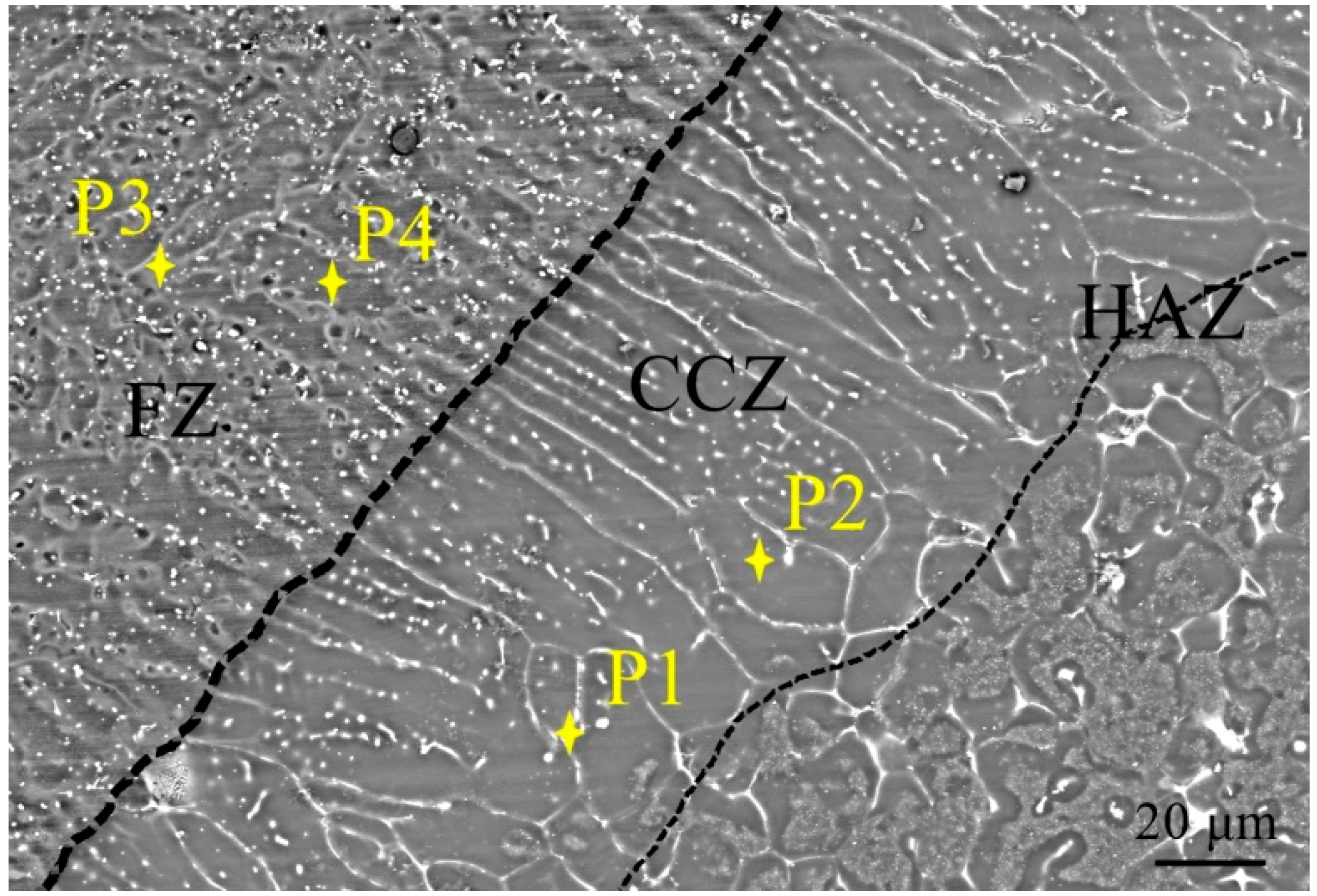
| Point | Atomic Content (%) | ||||
|---|---|---|---|---|---|
| Mn | Ce | Al | Mg | Possible Phase | |
| P1 | 0.53 | 3.42 | 0.58 | 95.47 | Mg95Ce3Mn1Al1 |
| P2 | 0.83 | 0.03 | 0.03 | 99.11 | Mg99Mn1 |
| P3 | 11.03 | 3.24 | 30.87 | 54.86 | Mg55Ce3Mn11Al31 |
| P4 | 0.02 | 0.0008 | 3.07 | 96.91 | Mg97Al3 |
© 2019 by the authors. Licensee MDPI, Basel, Switzerland. This article is an open access article distributed under the terms and conditions of the Creative Commons Attribution (CC BY) license (http://creativecommons.org/licenses/by/4.0/).
Share and Cite
Li, T.; Song, G.; Zhang, Z.; Liu, L. Mechanical Properties and Microstructures of Laser–TIG Welded ME21 Rare Earth Mg Alloy. Materials 2019, 12, 2188. https://doi.org/10.3390/ma12132188
Li T, Song G, Zhang Z, Liu L. Mechanical Properties and Microstructures of Laser–TIG Welded ME21 Rare Earth Mg Alloy. Materials. 2019; 12(13):2188. https://doi.org/10.3390/ma12132188
Chicago/Turabian StyleLi, Taotao, Gang Song, Zhaodong Zhang, and Liming Liu. 2019. "Mechanical Properties and Microstructures of Laser–TIG Welded ME21 Rare Earth Mg Alloy" Materials 12, no. 13: 2188. https://doi.org/10.3390/ma12132188