Article

Modeling and Optimization of the Thermal Performance of a Wood-Cement Block in a Low-Energy House Construction

1
Las.E.R. Laboratory, Department of Industrial and Information Engineering and Economics (DIIIE), University of L’Aquila, Piazzale Pontieri 1, Monteluco di Roio, L’Aquila I-67100, Italy
2
Via Salvemini 37/A, Sulmona I-67039, Italy
*
Author to whom correspondence should be addressed.
Energies 2016, 9(9), 677; https://doi.org/10.3390/en9090677
Submission received: 19 May 2016 / Revised: 12 August 2016 / Accepted: 14 August 2016 / Published: 24 August 2016

Abstract

:
The reduction of building energy consumption requires appropriate planning and design of the building’s envelope. In the last years, new innovative materials and construction technologies used in new or refurbished buildings have been developed in order to achieve this objective, which are also needed for reducing greenhouse gases emissions and building maintenance costs. In this work, the thermal conductance of a brick, made of wood and cement, used in a low-rise building, was investigated with a heat flow meter (HFM) and with numerical simulation using the Ansys® software package (Canonsburg, PA, USA). Due to their influence on the buildings’ thermal efficiency, it is important to choose an appropriate design for the building blocks. Results obtained by the finite element modeling of the construction material and by in-situ analysis conducted on a real building are compared, and furthermore a thermal optimization of the shape of the material is suggested.

Graphical Abstract

1. Introduction

In the last years, innovation in the building sector has been focused on the development and use of highly-insulating and sustainable materials. The recent European Directives have pushed research activities on the matter, as witnessed by the scientific literature. The frontiers of insulating materials are always evolving, and the issue of energy losses through the building envelope can be faced with materials that embody a high technological content. Several works have been published about the use and implementation in traditional buildings of aerogels [1,2,3,4], Phase-Change Materials (PCM) [5,6,7,8] or Vacuum Insulating Panels (VIP) [9,10,11,12].
A complete overview of insulation materials for the building sector is provided in a work of Schiavoni et al. [13], where a comparative analysis of several commercial insulating materials, classified as conventional, alternative and advanced, has been proposed. Conventional materials include stone wool, glass wool, expanded and extruded polystyrene, polyurethane, cellulose, cork, wood fiber, mineralized wood fiber, Lightweight Expanded Clay Aggregate (LECA), vermiculite and perlite; hemp, kenaf, flax, sheep wool, coir fiber, recycled rubber, jute fiber and recycled cardboard are refereed as alternative insulation materials; VIP, Gas Filled Panels (GFP) and aerogels are counted among the advanced insulation materials.
This work considers different parameters and characteristics, like thermal and acoustic properties, reaction to fire, water vapor resistance and Life Cycle Assessment (LCA). The comparison of the main features of the materials previously mentioned provides a useful guide for a proper design of wall insulation materials.
The paper expands the content of a previous one [14], that deals with insulation materials made of natural or recycled resources which are not (or scarcely) commercialized. In [14], the comparison was assessed in terms of thermal conductivity, specific heat, density, acoustic performance, without excluding data on the LCA.
A work by Jelle [15] investigated state-of-the-art, weakness and strength points of traditional and innovative materials and solutions suitable for thermal building insulation. Several properties and characteristics were investigated, compared and discussed, like thermal conductivity, mechanical strength, robustness and durability due to climate ageing. Amongst the wide panorama of insulation materials, a great attention has been addressed over the last decade to those which include natural or wood wastes. On one hand, this tendency is due to the need to improve the sustainability of the final product; on the other hand, research activities aim at studying materials that could reduce the waste dumping and the use of natural resources. For these reasons, over the last few years new building materials that include natural resources or process wastes have been developed, studied, tested and used.
The high potential of insulating materials containing renewable resources (namely, jute flax and hemp) has been demonstrated by Korjenic et al. [16], who proved that the properties of insulating board containing organic fibers are comparable to those of commonly used insulating boards. A work from Madurwar [17] reviewed the application of agro-waste in sustainable construction materials, in terms of physico-mechanical properties, methods of production and environmental impact. Aigbomian et al. [18] studied the influence of three kinds of sawdust modification (i.e., hot water boiling, alkaline treatment and the addition of different types of waste paper) on the compressive strength of wood-crete.
In [19] the influence of constituents on the properties of wood-based composites are studied and experimentally assessed. In a work by Adamopoulos et al. [20] the compressive strength, thermal conductivity and sound absorption coefficients have been assessed for gypsum-based products containing recovered rubber or wood particles. Other papers [21,22] investigated the physical and mechanical properties of wood-cement panels, together with their thermal performances. Particularly, in [21] the physical and mechanical characterization has been performed according to standards; for the thermal behavior of the panels, a small cubic test cell has been build, and then monitored by using heat flux meters and indoor-outdoor temperature probes. Then, the thermal conductivity of the wood-cement panel has been compared to the value obtained by performing a test complying standard ISO 8301 [23].
In [22] the same experimental set up has been employed in five wood-based test cells, and then the results have been compared to the ones obtained on a sixth test cell realized with hollow ceramic bricks. In this work it is stated that the method is suitable for low-mass building element. In [24] different insulation materials (i.e., containing waste olive seeds, ground PVC, wood chips, plaster and epoxy in different mix portions) were investigated, and their properties, in terms of unit weight, water absorption rate, ultrasonic penetration velocity, thermal conductivity coefficient, compressive and flexure strengths, were assessed and compared.
A recent work [25] studied the thermal and mechanical properties of wood aggregates, also proposing a short literary review on works dealing with these materials. In particular, compressive strength tests and one-dimensional heat flow model have been used to define the main characteristics of mineralized wood concrete, (a conglomerate containing treated wood wastes). A paper by Raut et al. [26] deals with waste-create bricks, obtained by adding various waste materials in different proportions to the raw material. The work focuses on the review of design and development of waste-created bricks, and proposes a comparison of bricks that include different wastes, according to various physico-mechanical and thermal properties. It also contains a discussion comparing compressive strength and water absorption capabilities.
The influence of the proportion of wood aggregates on the thermal conductivity, mechanical strengths and the porosity of a clay-cement-wood composite has been experimentally assessed in [27]. The work showed that the addition of wood to clayed concrete lowers the mechanical strength and increases its deformability, but enhances its insulation capabilities.
However, none of the above papers deals with the assessment of the thermal performance of such materials after the installation, nor performs a numerical simulation of such materials. To fill this gap, this work is proposed, since it compares results of numerical simulations with in situ measurements. The aim of this paper is to characterize a new building material also used as a bearing structure: a wood-cement block, that hosts in the inside an insulating layer of expanded polystyrene (EPS).
The study was carried out by measuring with a heat flow meter the thermal conductance of a wall of a building realized with these blocks, during the winter season. Then, a simulation with the Ansys® computer program, which uses the finite element method (FEM), has been performed, imposing as boundary conditions the same ones used during the measurement campaign. Results have been compared, and an optimization of the shape of the inner holes is suggested to enhance the thermal performance of the brick.
Structural blocks of cement bonded wood-fiber are used for housing, thanks to their seismic safety and thermal and acoustic insulation. These construction materials are widespread in the north of Europe, especially in countries rich in wood-processing industries, because of the potential use of wood wastes.
The block typology studied in this work, and shown in Figure 1, is produced according to the norm UNI EN 15498 [28]. The main features of its components, in terms of thermal conductivity (λ), density ( ρ ), thermal capacity (T.C.), vapour resistance (V.R.), and thickness (s) are gathered from the product data-sheet provided by the manufacturer [29].
Blocks are produced by molding a mixture of fir chops and Portland cement, and then laid dry; products are ecological, fireproof, highly breathable and quite insulating. This last property might be enhanced by inserting additional insulating layers (like EPS or extruded polystyrene—XPS), fixed to the block directly during manufacturing.
The holes inside the blocks host the concrete casting, which is reinforced in the construction site. The main parameter used for the comparison between provided data and the numerical results is the thermal conductance given by the producer and equal to Cp = 0.24 W/m2·K, where the subscript “p” stands for “producer”. According to the data sheet, this value takes into account an internal and external plaster layer (λ = 1 W/mK; ρ = 1800 kg/m3; T.C. = 1 kJ/kg·K; V.R. = 10; s = 15 mm).

2. Methods

2.1. Heat Flow Meter

In situ measurements were performed on a low-rise single-house recently built in the immediate outskirts of the city of L’Aquila, in central Italy (climatic zone: E; Degree Days: 2514), during the winter season. The heat flow meter method has been applied, following recommendations provided in ISO 9869 [30].
In order to minimize indoor and inner-surface temperature variation, it is advisable to perform measurements on an unused room of a building. In this case, during the measurement period the probes were positioned in an unoccupied guest room, on a north-west-facing and easily accessible wall. A preliminary qualitative thermographic survey was carried out to identify the best place to locate the flux plate and the temperature probes, as far as possible from cold bridges.
The thermal inspection allowed us to identify, in the wall, and near the place of the probe location, the centre of the hole (that hosts the reinforced concrete) and the side of this hole (corresponding to the wood-cement). Therefore, it was decided to perform two consecutive campaigns, locating the temperature probes in two different points of the block, namely point A and point B of Figure 1. The measurements lasted three days for point A and four days for point B.

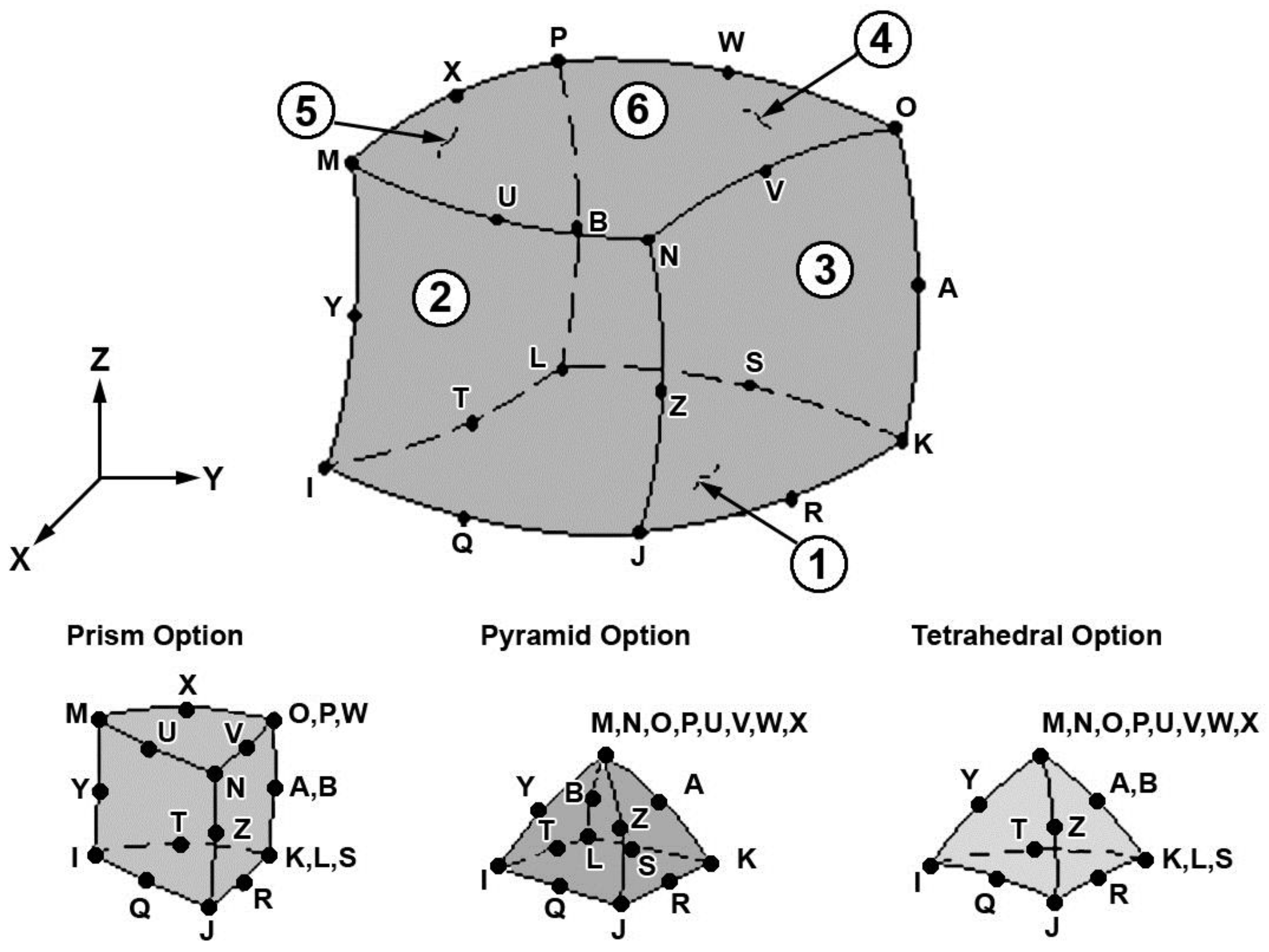
2.2. FEM Simulations
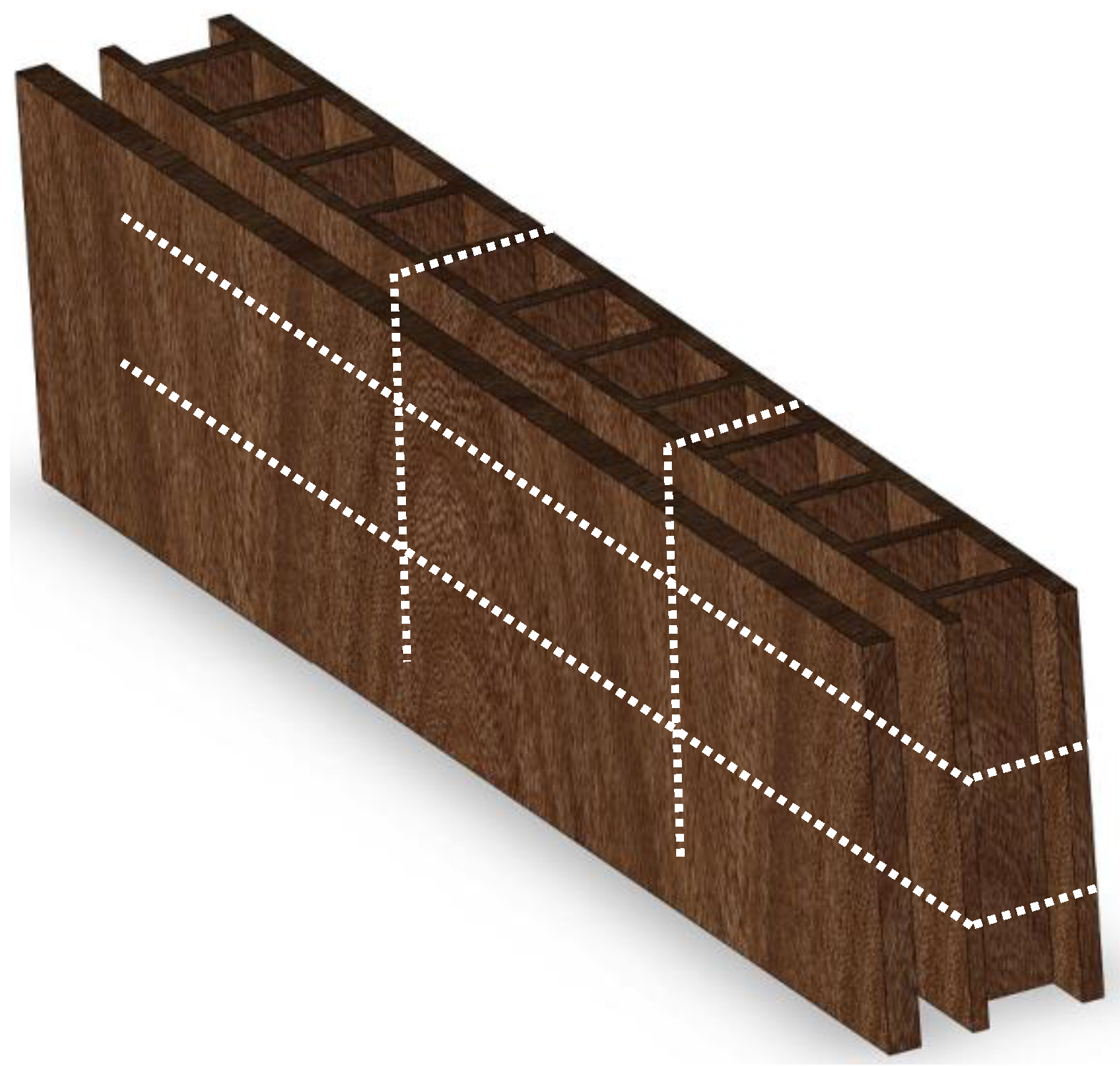
The goal of the performed FEM analysis is to provide an efficient numerical model to evaluate the thermal behaviour of the insulating cement—wood based material. Two different models have been set: one for a single block of material and another for a block surrounded by others, simulating a piece of wall, in order to understand if there are side effects linked to the presence of other blocks. The software used to make the 3D model was SolidWorks. A secondary goal of the simulation is the investigation of the influence of different temperatures on the model, therefore the results are gathered by setting different temperature conditions. In particular, numerical simulations of a single block (single block configuration—SBC) and of a small wall made by 3 × 3 bricks as depicted in Figure 2 (nine block configuration—9BC) have been performed, in order to obtain the thermal conductance of the material. Main data used in the simulation are:
  • System geometry;
  • Layer configuration;
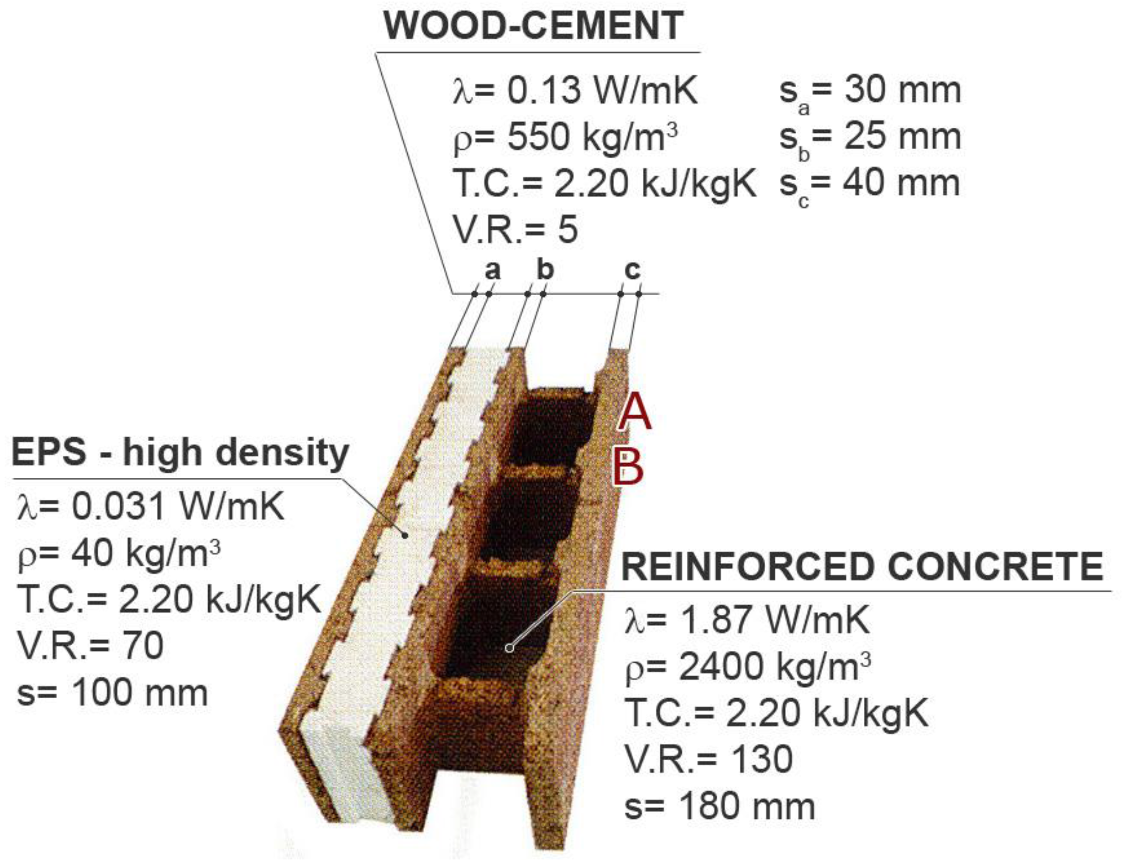
  • Chemical/physical material properties;
  • Thermal conductivity and global transmittance for comparing the obtained results.
The first simulation aims at investigating the single block, therefore no geometry simplification was required. It is important to notice that during the FEM analysis the empty regions, filled in the real block with reinforced concrete and EPS, have been properly considered, sharing the overall model in different regions with different physical properties. Concerning the model used for the simulation of the 9BC, two simplifications were needed, due to the size of the overall model:
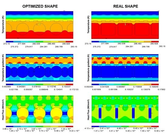
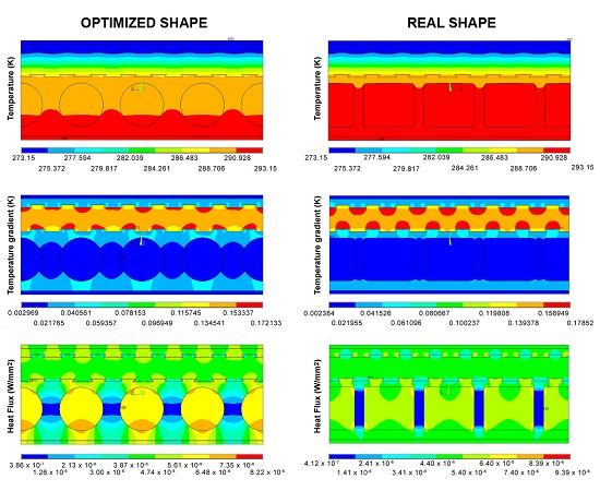
  • A geometry simplification for the reinforced concrete seats: the rounded shape of the corner has been replaced by an angular one;
  • A simplification of the EPS seat: a straight line has been used, running in the middle of the original swallow-tail shape.
In this way, the mesh operation has been eased and the calculation effort was compatible with the availability of the hardware, thus reducing numerical errors and the time required for calculation. The simulation of the system behaviour has been obtained through Ansys®, more precisely through the Mechanical suite. The element type SOLID90, depicted in Figure 3, has been used: it consists of a 20-node brick element; the temperature is the only degree of freedom [31].
The main input data for this element type are thermal conductivity (a value for each main direction) and density. Nodal temperature, heat flux and average face temperature are some of the main outputs provided by the element. Special attention has to be paid to geometric degeneration of the elements, since for this particular element type this drawback is particularly important and it can lead to numerical instability.

3. Results

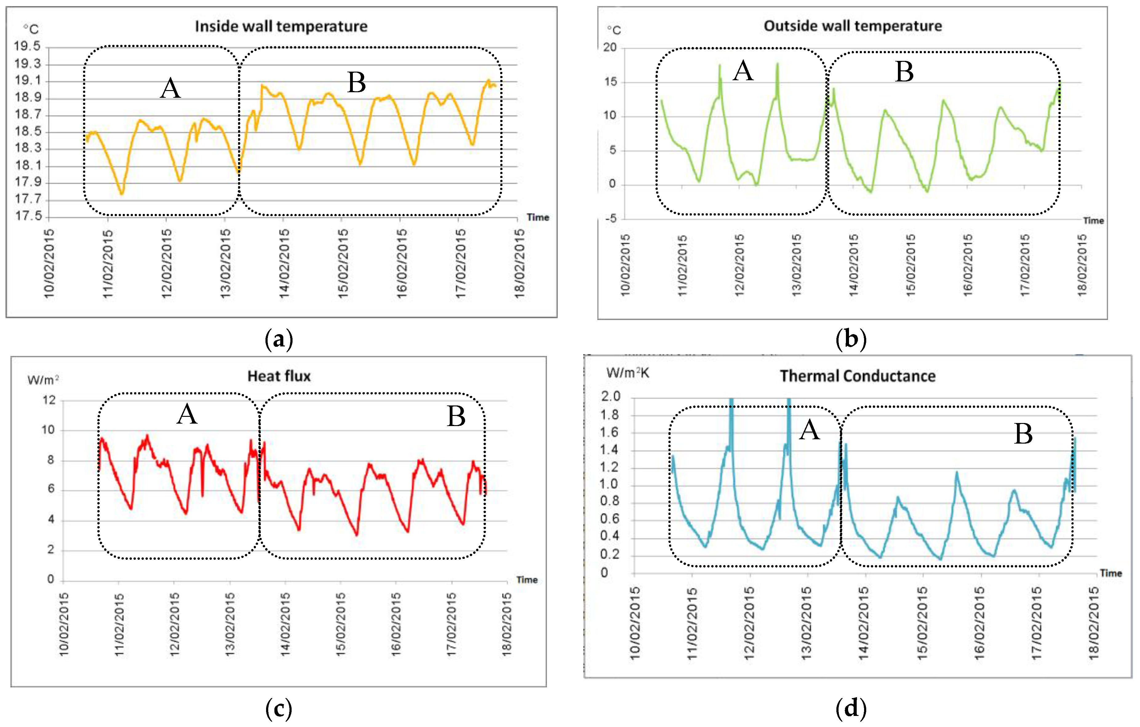
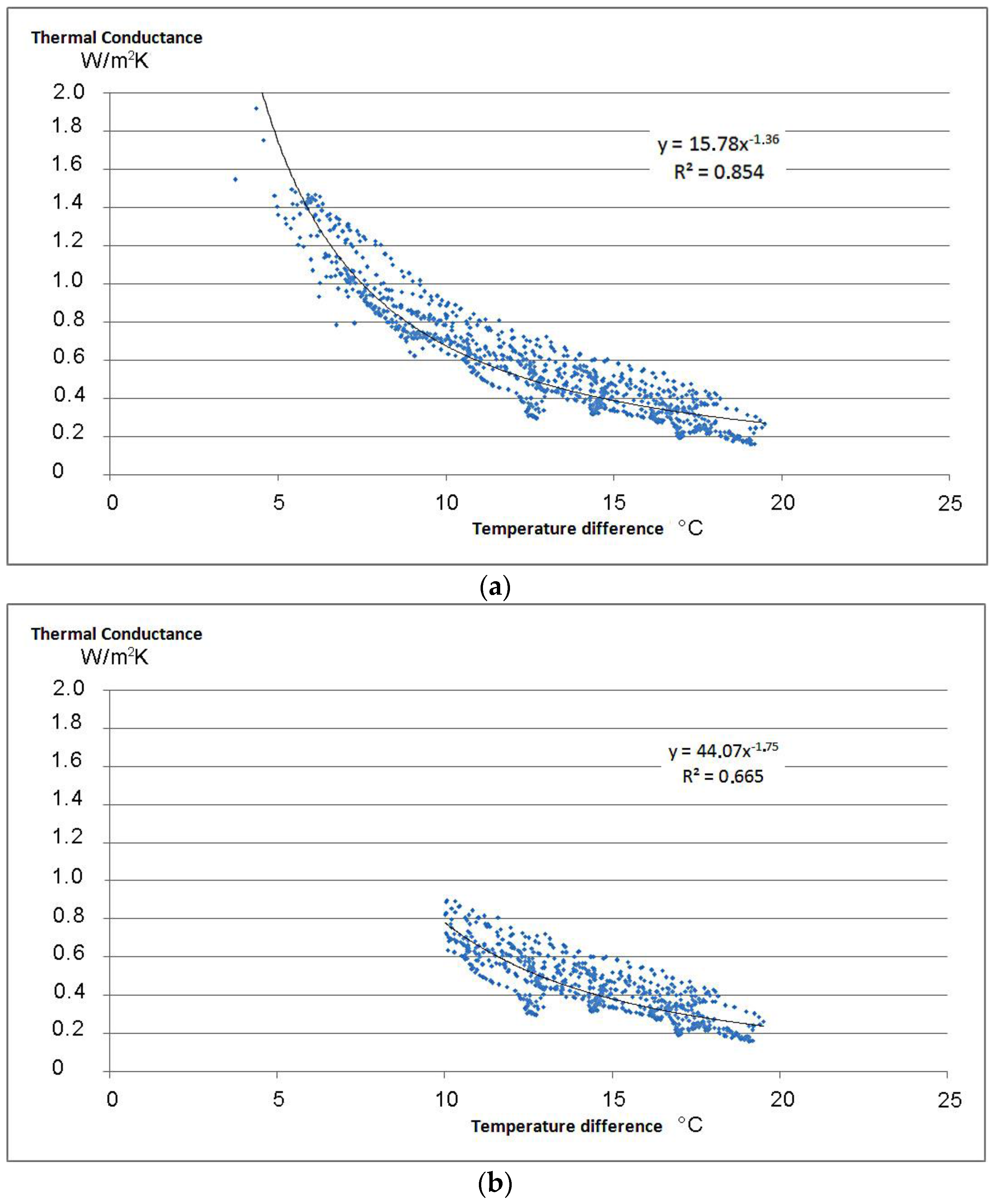
3.1. Heat Flow Meter Measurements

The data logged with the heat flow meter have been plotted for both point A and B of Figure 1. The change of probe position causes a slight (on the order of 1 °C) increase of the mean inside wall temperature, as shown in Figure 4a). The data plotted in Figure 4 are the instantaneous values of quantities recorded by the logger every 10 min. The graphs of Figure 4a,b show the instantaneous values of the inside and outside wall temperatures, while the graph of Figure 4c shows the instantaneous heat flow recorded and measured with the flux plate. The last graph (Figure 4d) shows the thermal conductance of the wall, retrieved as the ratio between the flux and the surface-to-surface temperature difference.
The general trend of the inside wall temperature follows the alternation between day and night, although the maximum temperature oscillation of the internal wall is 1.3 °C. The external wall temperature ranges from −1.1 °C to 17.8 °C, probably due to the unpredicted direct solar irradiation. The thermal conductance values provided by the data analysis software with the progressive average method are 0.57 W/m2·K and 0.46 W/m2·K, respectively, for points A and B. To be sure that no operational mistakes were made during the measurement campaigns, another survey has been performed, leading to analogous results.
The difference between these values can be explained by the high variability of temperatures, but, in any case, such results are almost double with respect to the value provided by the manufacturer. This anomaly is due both to the high time lag of this kind of block (equal to 24.3 h) and to the low periodic thermal transmittance Yie equal to 0.002 W/m2·K [29], (that implies a decreasing factor of 0.009 corresponding to a quasi-perfect heat storage medium). Knowing these characteristics given by the product datasheet, it is possible to suppose that transient effects deeply influence the heat flow meter measurements. Therefore, heat flow meter campaigns should be prolonged (i.e., conducted as multiples of 24 h), although it is impossible to guarantee stable or at least periodic external conditions.
In Figure 5a, the distribution of all measured data (blue dots) of thermal conductance values obtained during the whole campaign is shown, plotted against the inside-outside wall temperature difference, and excluding negative values (that have no physical meaning). By eliminating those data—about 6%—recorded with a temperature difference lower than 10 °C (the minimum value suggested by standard), the graph assumes the trend of Figure 5b). The black lines of Figure 5a,b are the plots of the exponential regression analyses, whose equations are written in the Figures, with R2 values of 0.8544 and 0.6653.

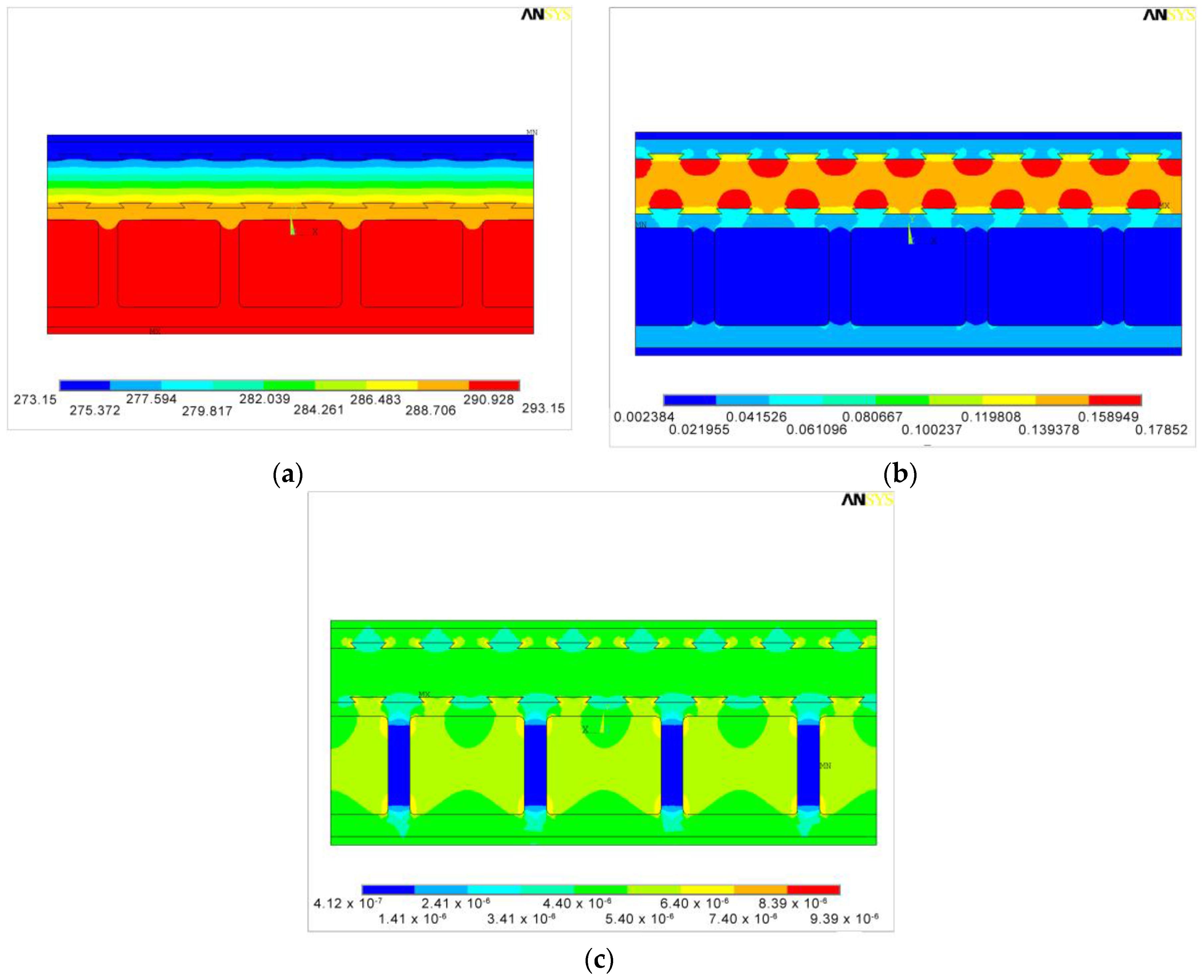
3.2. FEM Simulations

The analyses of the single block and of the configuration of nine blocks have been performed under the hypothesis of homogeneous, continuous and isotropic materials, steady-state condition, one-dimensional heat flow and absence of material discontinuities. In both configurations two cases have been analyzed, different in the fixed temperatures:
  • Case 1: outside wall temperature Tout = 0 °C, inside wall temperature Tin = 20 °C;
  • Case 2: outside wall temperature Tout = −5 °C, inside wall Tin = 20 °C;
Results regarding temperature, temperature gradient and heat flux are shown.

3.2.1. FEM Simulation of a Single Block (SBC)

Case 1

Figure 6 shows the results obtained for the single block. It is worth noting the temperature distribution (Figure 6a) across the sides of the holes for the concrete cast. Such distribution, due to the different thermal conductivity of concrete and wood-cement, can be enhanced by reducing the temperature range (as in Figure 7a).
The gradient distribution (Figure 6b) is coherent with the block stratigraphy, since the higher values (orange and red areas) correspond to the insulating layer, while the blue areas correspond to the more conductive layers. It is also noticeable the prevailing thermal effect of the reinforced concrete on the thin wood-cement side. This portion of the block, therefore, constitutes a kind of “thermal bridge”, where the heat flux is lower, as shown in Figure 6c. This particular behavior can be due to a bidimensional heat flux: the heat is obstructed by the wood-cement rib and naturally passes through the more conductive layer, i.e., the concrete, so the heat flux assumes the hilly shape (green sides of the lower part of Figure 6c. This phenomenon can be better visualized by reducing the heat flux range, as shown in Figure 7b. Moreover, it is possible to notice that the heat flux is influenced by the presence of thicker wood layers, causing uneven entering flux distribution, and by the swallow-tail shape of the EPS layer, which decreases the exiting flux distribution.
Considering that the mean value of the heat flux is equal to 4.8 W/m2, and knowing the temperature difference (20 °C), the thermal conductance is 0.24 W/m2·K. This value equals the one provided by the manufacturer.

Case 2

As for the previous case, simulation results for temperature, temperature gradient and heat flux obtained with a higher temperature difference are shown below in Figure 8.
In this case, the heat flux equals 6.0 W/m2, and the thermal conductance is, once again, 0.24 W/m2·K. Therefore, the model is numerically stable, and not influenced by the boundary condition imposed, providing reliable results.

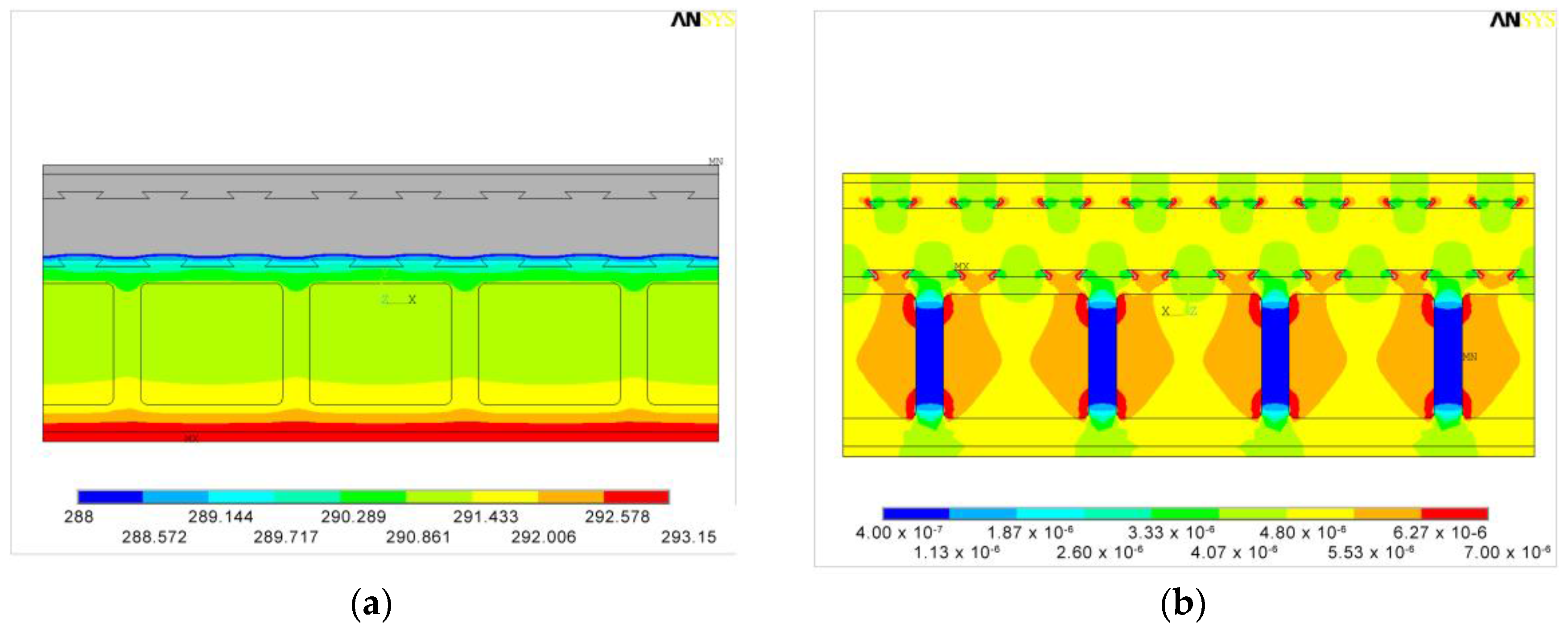
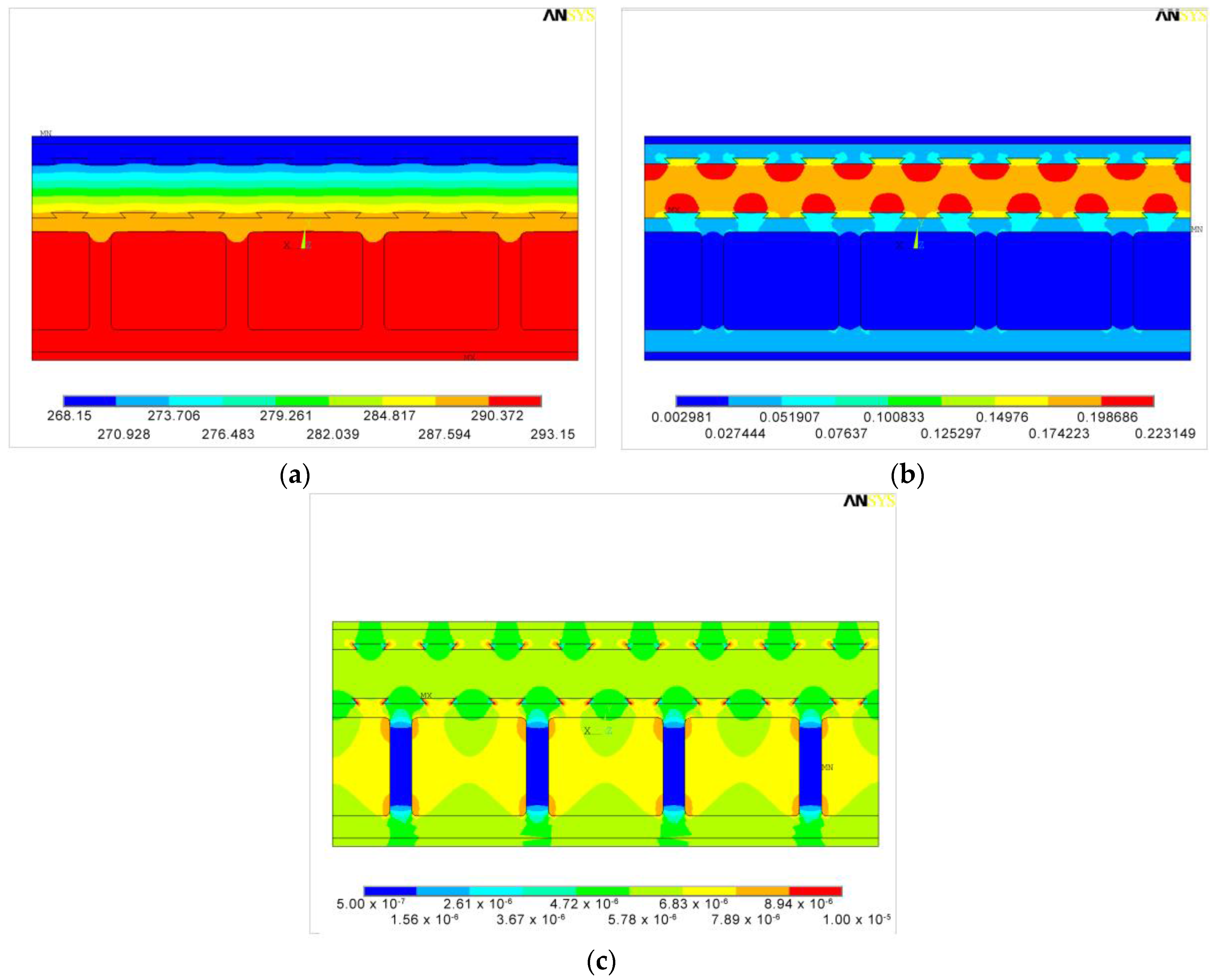
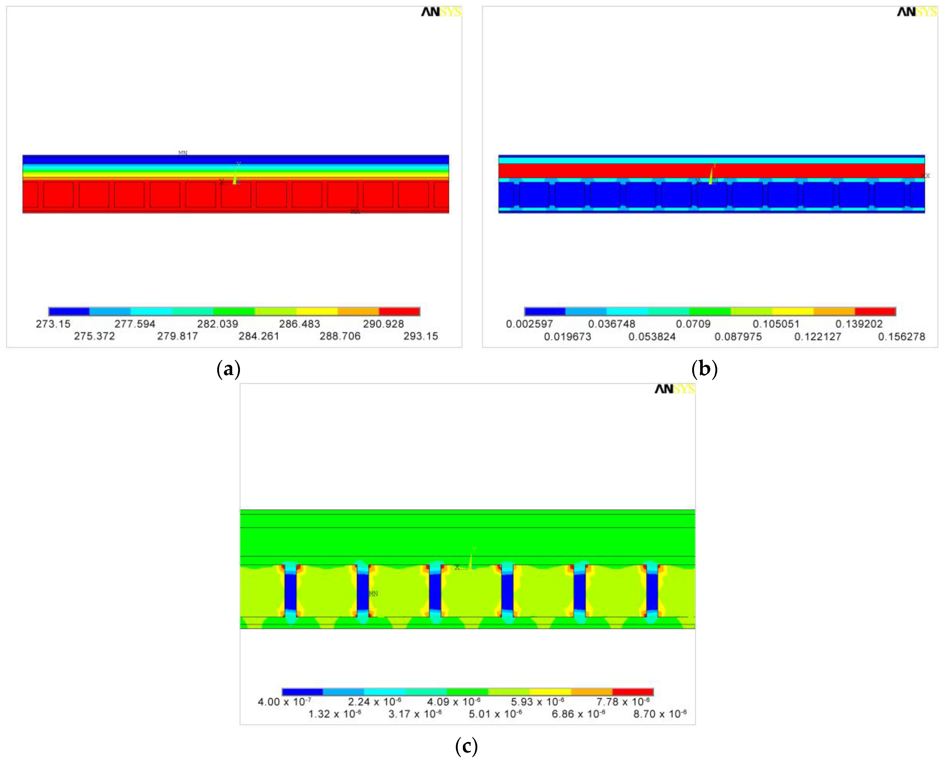
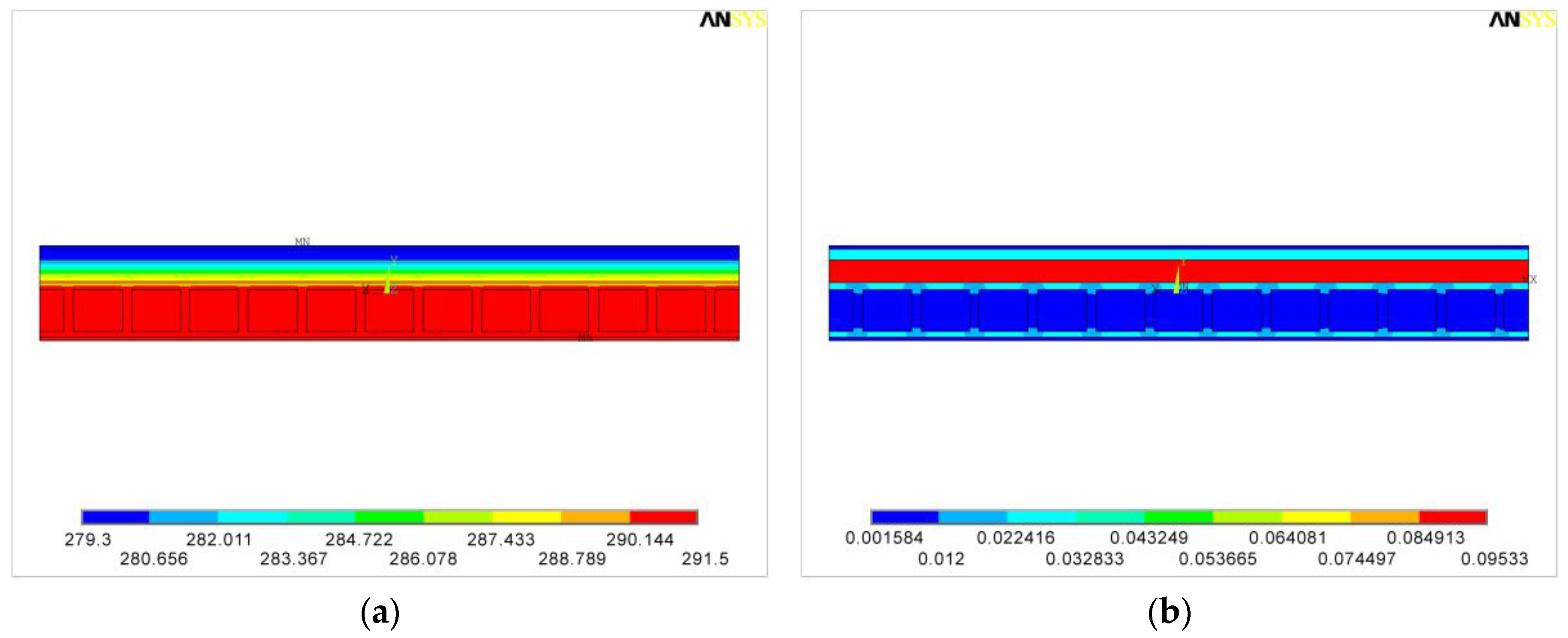
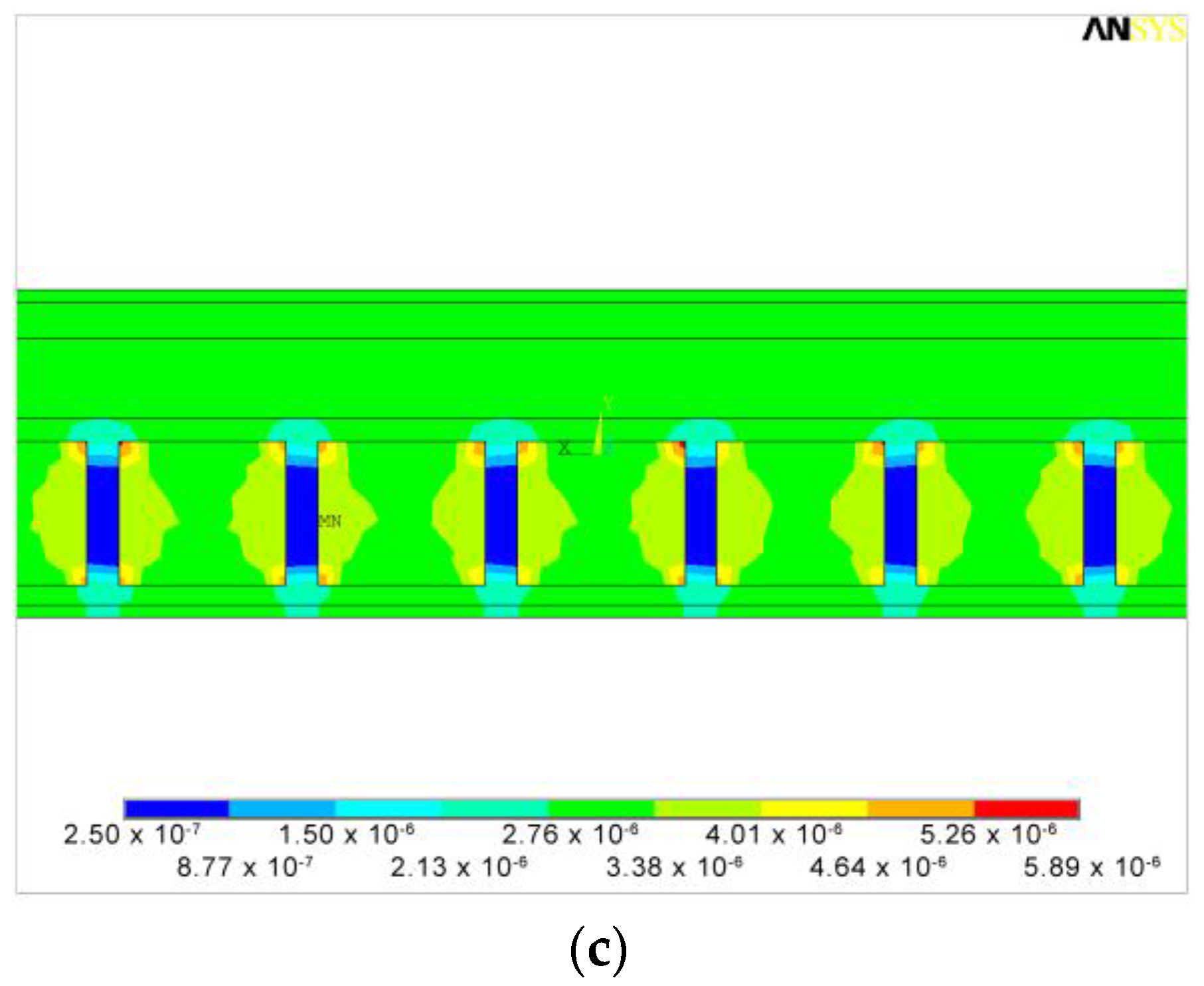
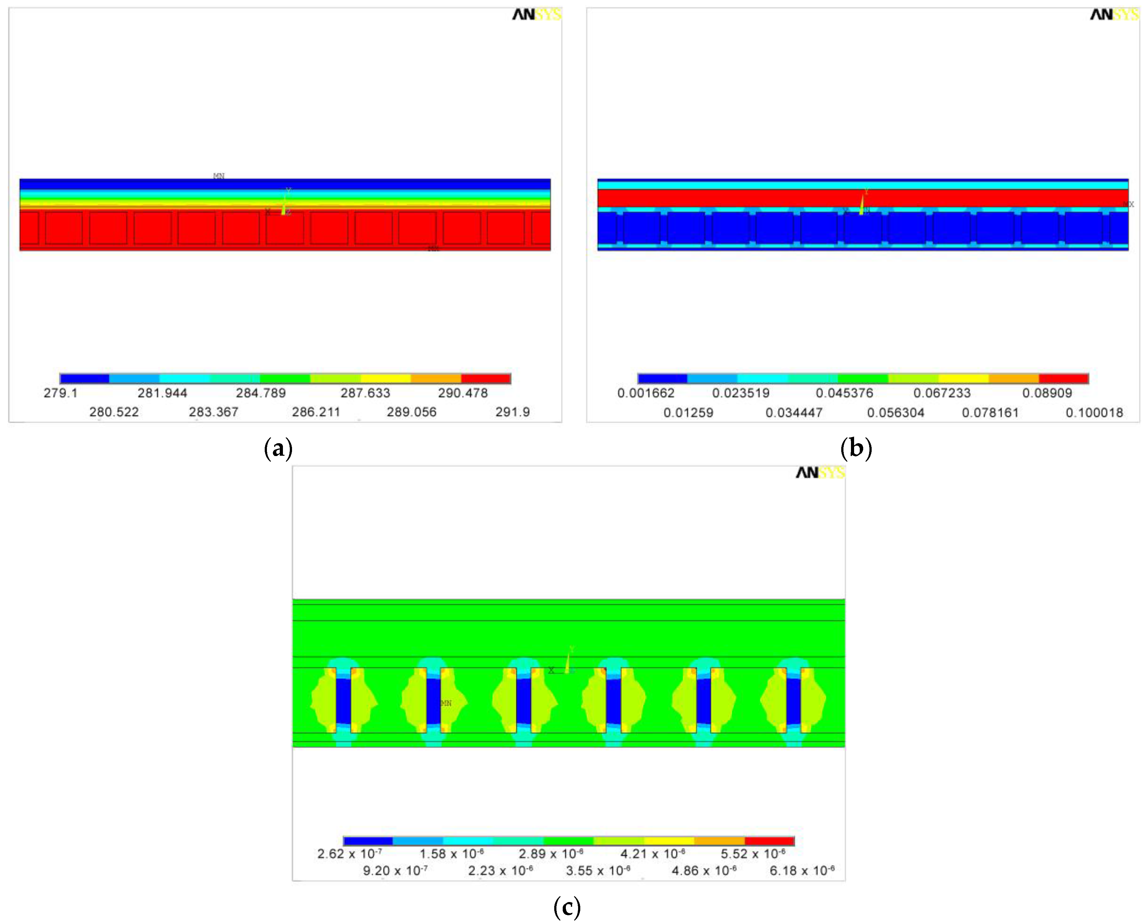
3.2.2. FEM Simulation of Nine Adjacent Blocks (9BC)

Regarding temperature, temperature gradient and heat flux, the results are shown and detailed for each case also in this configuration. As in the previous simulations, the element type SOLID90 with 20-node has been used, while the mesh has 156,317 elements. The possibility of using a lower number of elements despite a wider geometry is due to the simplifications adopted in the model. This reduces the time required for running the simulations, and the probability of numerical errors.
In order to verify if a further variation of the imposed temperatures could affect the final result, it has been decided to repeat the simulations, imposing the mean temperatures that occurred during the experimental campaign in point A and point B.
Therefore, two additional simulations have been run for the 9BC:
  • Case 3: outside wall temperature Tout = 6.2 °C, inside wall temperature Tin = 18.4 °C;
  • Case 4: outside wall temperature Tout = 6 °C, inside wall temperature Tin = 18.7 °C.

Case 1

Qualitatively, results shown in Figure 9a,b agree with those obtained for the single block configuration, unlike the distribution through the insulating layer, whose geometry has been simplified. From the observation of the thermal gradient, it is possible to verify the coherence with the system physical reality: higher gradients occur in correspondence to materials with higher thermal resistance. Moreover, in the enlarged view of Figure 9c it is possible to notice the thermal bridge between concrete and wood. The latter increases the heat flux in the area adjacent to the concrete seat.
The heat flux becomes quite uniform in the insulating layer, where it equals 4.8 W/m2, thus the thermal conductance is equal to 0.24 W/m2·K, in accordance to what has been retrieved for case 1 of the single block configuration.

Case 2

Trends shown in Figure 10 are analogous to the ones of the previous case; now, the heat flux is 6.0 W/m2, and the thermal conductance is equal to 0.24 W/m2·K, being the temperature gradient equal to 25 °C.

Case 3

Trends of Figure 11 are analogous to the ones of the previous cases; the heat flux is 2.9 W/m2, the thermal conductance is equal to 0.24 W/m2·K, being the temperature gradient between the two sides equal to 12.2 °C.

Case 4

Simulation results are shown in Figure 12. The heat flux is 3.0 W/m2, the temperature gradient between the two sides is 12.8 °C and the thermal conductance is 0.23 W/m2·K.
Based on these results, the following outcomes can be stated:
(1)
Results did not vary with different wall temperatures, therefore they are not influenced by the imposed boundary conditions;
(2)
Results did not vary with different block configurations. This means that relevant mutual exchanges between adjacent blocks do not occur, and that the study of this kind of material can be focused even on a single block;
(3)
Results are coherent with the value provided by the manufacturer, this means that the fem simulations (in terms of modeled block and boundary conditions) well represent the conditions of the theoretical calculus;
(4)
The models and geometries employed for the SBC ensure the numerical stability of the simulation;
(5)
The geometrical simplifications adopted for the study of configuration 9BC, needed to reduce the computational effort of the simulations, guarantee a proper modeling of the wall behavior;
(6)
Results obtained via fem simulation differ from the ones obtained via in field measurements, since the latter are affected by the dynamic thermal behavior of the wall;
(7)
Wood-cement blocks with concrete cast provide for both the structural and thermal properties of building wall; moreover, the overall thermal conductivity of these materials is lower than other materials, commonly employed as bearing structures, like hollow bricks [32,33].
All these considerations allow us to affirm that numerical simulations can be a useful tool for producers in the design phase of structure components, since they allow one to replicate the thermal behavior of building materials.
Particularly, simulations allow to study different possible configurations of materials (like, for instance, different cavity concentration for hollow bricks [33]), and to foresee the overall insulating capabilities of the components.
Starting from these strength points, it has been decided to study a different wood-cement block configuration. The simulation of the new configuration has been carried out on a single block, hypothesizing that results would not have varied if a configuration with multiple blocks had considered and taking into account the results and outcomes mentioned before.

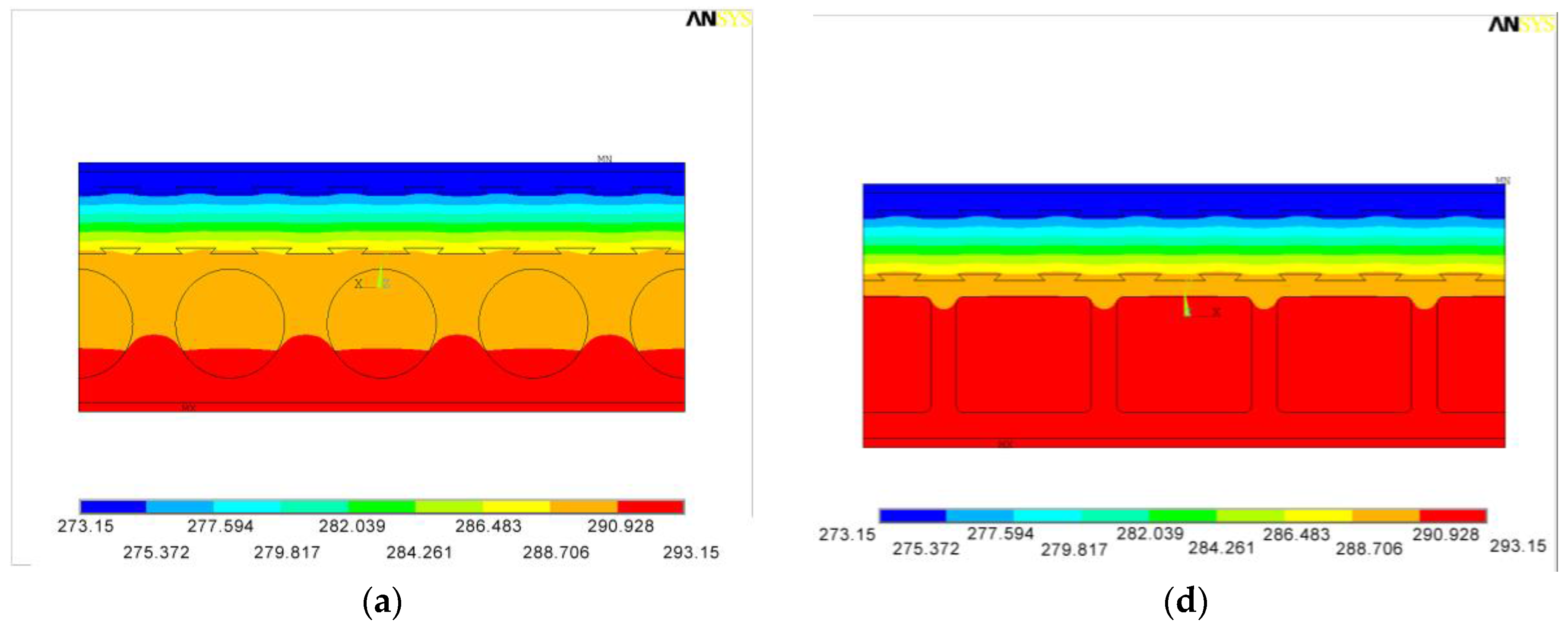
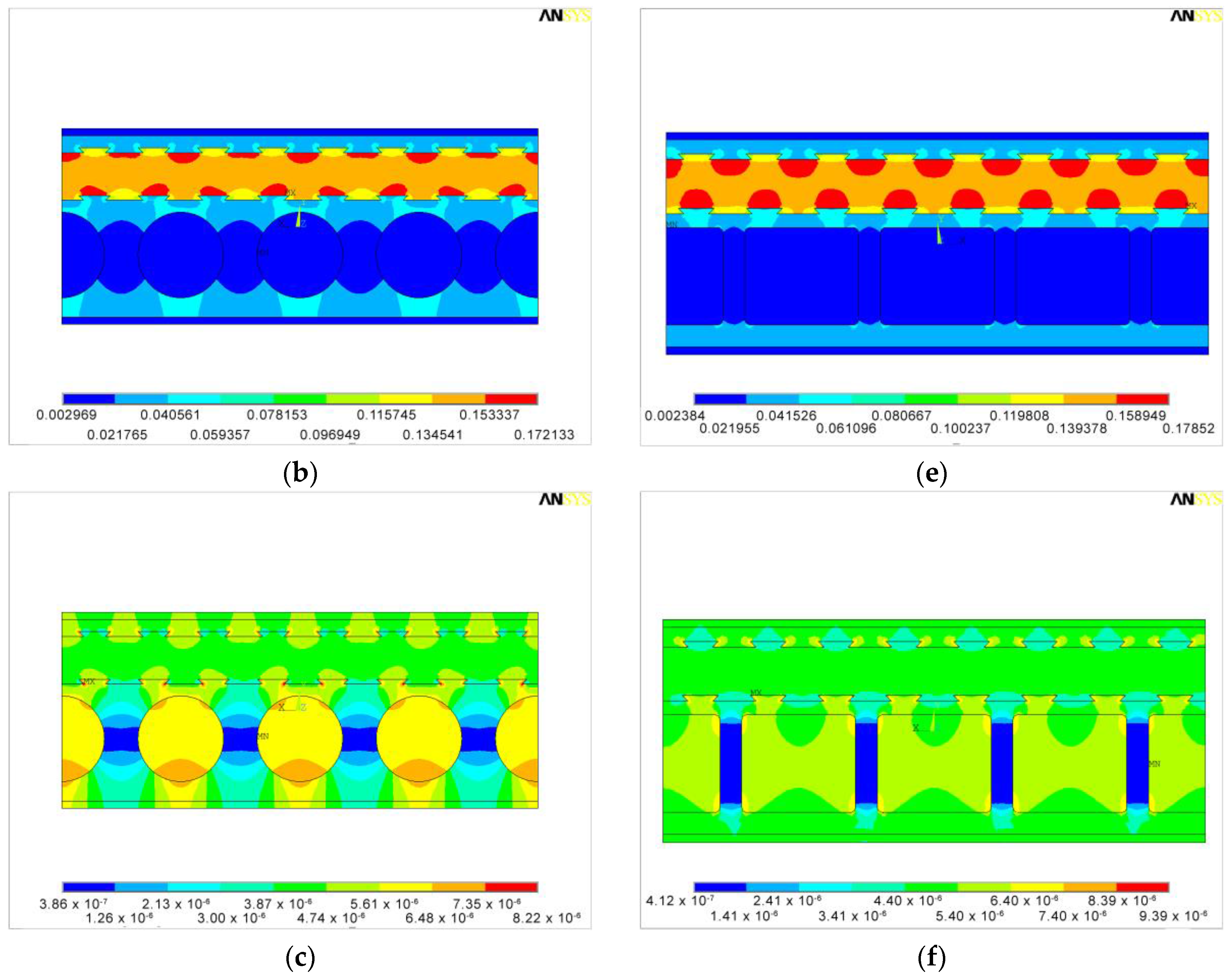
4. Shape Optimization

A great advantage of the use of a FEM simulation software is the possibility to exploit different configurations. In this case, a numerical analysis of the thermal performance of a new brick shape has been carried out. In particular, the new shape consists in rounded seats for the concrete cast. The evaluation did not consider the bearing capability effects.
The left side of Figure 13 shows the results regarding temperature, temperature gradient and heat flux for the optimized shape, whilst the right side shows the corresponding ones for the current shape.
The seat shape variation limits the high temperature region. This implies a better insulation capability, due to the elimination of corner effects and to the presence of much wood, in place of reinforced concrete, which is more conductive. In this case, imposing outside and inside wall temperatures equal to 0 °C and 20 °C respectively, the simulated heat flux is 4.5 W/m2, therefore the thermal conductance is Co = 0.225 W/m2·K, 6.3% lower than the corresponding value for the single block configuration.

5. Conclusions

The thermal conductance of a sustainable building element, namely a wood-cement block, also used as bearing structure, has been analyzed by using data provided by:
-
the manufacturer,
-
on-site HFM measurement on a real building made of this kind of material, and
-
FEM simulations.
In all three cases, the hypotheses are based on:
-
homogeneous, continuous and isotropic materials,
-
steady-state condition,
-
one-dimensional heat flow and absence of material discontinuities.
Two different configurations have been studied by the FEM analysis performed via the Ansys® computer program: a single block configuration and an assembly of nine blocks. Simulations were performed by imposing different temperatures as boundary conditions. Numerical results are not influenced neither by the imposed boundary conditions nor by the configuration selected.
Results obtained by using the FEM analyses agreed with those obtained from the theoretical one, proving that an accurate 3D model of the brick allows to truly represent its thermal performance. Possible geometry simplifications (necessary, for example, to reduce numerical errors and the time required for calculation) should be thoroughly considered, in order to guarantee a proper modeling of the behavior of the wall.
Standing on simulations results, the heat flow was obstructed by the wood-cement rib and passes through the more conductive layer, i.e., the concrete. Therefore the heat flux assumes the hilly shape, while this portion of the block constitutes a kind of “cold bridge”.
Such behavior seems to be confirmed by results obtained using the heat flow meter, which has been positioned in correspondence to both to the rib and to the concrete-cast seat. However, the HFM results are quite different from the others, probably because of the great influence of unsteady state conditions, and because of the brick’s low periodic dynamic transmittance and low decrement factor, which have not been measured but obtained from the product datasheet. These dynamic parameters might have influenced data so deeply, that the applied average method does not allow to represent the material real thermal conductance. For this reason, the extension of the measurement campaign would not refine the final value, since unsteady conditions might occur. In any case, this important issue will be better investigated in a future work.
Finally, a different concrete-seat shape that could limit the rib effect has been designed, modeled and simulated by Ansys®. The results show that a round section in place of a squared one could reduce by more than 6% the brick thermal conductance, although the load-bearing consequences were not investigated.

Acknowledgments

The Authors would like to thank Gruppo Legnobloc s.r.l., for providing the technical data and for suggesting the site for the experimental campaign.

Author Contributions

Domenica Paoletti conceived and designed the experiments; Iole Nardi and Tullio de Rubeis performed the experiments and wrote the paper; Edoardo Buzzi performed the FEM analysis and wrote the concerning sections; Stefano Sfarra, Dario Ambrosini and Domenica Paoletti revised the whole work.

Conflicts of Interest

The authors declare no conflict of interest.

References

  1. Baetens, R.; Jelle, B.P.; Gustavsen, A. Aerogel insulation for building applications: A state-of-the-art review. Energy Build. 2011, 43, 761–769. [Google Scholar] [CrossRef]
  2. Stahl, T.; Brunner, S.; Zimmermann, M.; Ghazi Wakili, K. Thermo-hygric properties of a newly developed aerogel based insulation rendering for both exterior and interior applications. Energy Build. 2012, 44, 114–117. [Google Scholar] [CrossRef]
  3. Serina, N.G.S.; Jelle, B.P.; Sandberg, L.I.C.; Gao, T.; Wallevik, O. Experimental investigations of aerogel-incorporated ultra-high performance concrete. Constr. Build. Mater. 2015, 77, 307–316. [Google Scholar]
  4. Ibrahim, M.; Wurtz, E.; Biwole, P.H.; Achard, P.; Salle, H. Hygrothermal performance of exterior walls covered with aerogel-based insulating rendering. Energy Build. 2014, 84, 241–251. [Google Scholar] [CrossRef]
  5. Soares, N.; Costa, J.J.; Gaspar, A.R.; Santos, P. Review of passive PCM latent heat thermal energy storage systems towards buildings’ energy efficiency. Energy Build. 2013, 59, 82–103. [Google Scholar] [CrossRef]
  6. Lee, K.O.; Medina, M.A.; Raith, E.; Sun, X. Assessing the integration of a thin phase change material (PCM) layer in a residential building wall for heat transfer reduction and management. Appl. Energy 2015, 137, 699–706. [Google Scholar] [CrossRef]
  7. Lee, K.O.; Medina, M.A.; Sun, X. On the use of plug-and-play walls (PPW) for evaluating thermal enhancement technologies for building enclosures: Evaluation of a thin phase change material (PCM) layer. Energy Build. 2015, 86, 86–92. [Google Scholar] [CrossRef]
  8. Serrano, S.; Barreneche, C.; Fernández, A.I.; Farid, M.M.; Cabeza, L.F. Composite gypsum containing fatty-ester PCM to be used as constructive system: Thermophysical characterization of two shape-stabilized formulations. Energy Build. 2015, 86, 190–193. [Google Scholar] [CrossRef]
  9. Fricke, J.; Heinemann, U.; Ebert, H.P. Vacuum insulation panels—From research to market. Vacuum 2008, 82, 680–690. [Google Scholar] [CrossRef]
  10. Kwon, J.S.; Choong, H.J.; Jung, H.; Song, T.H. Effective thermal conductivity of various filling materials for vacuum insulation panels. Int. J. Heat Mass Transf. 2009, 52, 5525–5532. [Google Scholar] [CrossRef]
  11. Baetens, R.; Jelle, B.P.; Thue, J.V.; Tenpierik, M.J.; Grynning, S.; Uvsløkk, S.; Gustavsen, A. Vacuum insulation panels for building applications: A review and beyond. Energy Build. 2010, 42, 147–172. [Google Scholar] [CrossRef]
  12. Alam, M.; Singh, H.; Limbachiya, M.C. Vacuum Insulation Panels (VIPs) for building construction industry—A review of the contemporary developments and future directions. Appl. Energy 2011, 88, 3592–3602. [Google Scholar] [CrossRef]
  13. Schiavoni, S.; D’Alessandro, F.; Bianchi, F.; Asdrubali, F. Insulation materials for the building sector: A review and comparative analysis. Renew. Sustain. Energy Rev. 2016, 62, 988–1011. [Google Scholar] [CrossRef]
  14. Asdrubali, F.; D’Alessandro, F.; Schiavoni, S. A review of unconventional sustainable building insulation materials. Sustain. Mater. Technol. 2015, 4, 1–17. [Google Scholar] [CrossRef]
  15. Jelle, B.P. Traditional, state-of-the-art and future thermal building insulation materials and solutions—Properties, requirements and possibilities. Energy Build. 2011, 43, 2549–2563. [Google Scholar] [CrossRef]
  16. Korjenic, A.; Petránek, V.; Zach, J.; Hroudová, J. Development and performance evaluation of natural thermal-insulation materials composed of renewable resources. Energy Build. 2011, 43, 2518–2523. [Google Scholar] [CrossRef]
  17. Madurwar, M.V.; Ralegaonkar, R.V.; Mandavgane, S.A. Application of agro-waste for sustainable construction materials: A review. Constr. Build. Mater. 2013, 38, 872–878. [Google Scholar] [CrossRef]
  18. Aigbomian, E.P.; Fan, M. Development of wood-crete from treated sawdust. Constr. Build. Mater. 2014, 52, 353–360. [Google Scholar] [CrossRef]
  19. Ledhem, A.; Dheilly, R.M.; Benmalek, M.L.; Quéneudec, M. Properties of wood-based composites formulated with aggregate industry waste. Constr. Build. Mater. 2000, 14, 341–350. [Google Scholar] [CrossRef]
  20. Adamopoulos, S.; Foti, D.; Voulgaridis, E.; Passialis, C. Manufacturing and properties of gypsum-based products with recovered wood and rubber materials. BioResources 2015, 10, 5573–5585. [Google Scholar] [CrossRef]
  21. Krüger, E.L.; Adriazola, M.; Matoski, A.; Iwakiri, S. Thermal analysis of wood-cement panels: Heat flux and indoor temperature measurements in test cells. Constr. Build. Mater. 2009, 23, 2299–2305. [Google Scholar] [CrossRef]
  22. Krüger, E.L.; Adriazola, M. Thermal analysis of wood-based test cells. Constr. Build. Mater. 2010, 24, 999–1007. [Google Scholar] [CrossRef]
  23. International Organization for Standardization (ISO). ISO 8301: 1991. Standard Test Method for Steady-State Heat Flux Measurements and Thermal Transmission Properties by Means of the Heat Flow Meter Apparatus; ISO: Geneva, Switzerland, 1991. [Google Scholar]
  24. Binici, H.; Aksogan, O. Eco-friendly insulation material production with waste olive seeds, ground PVC and wood chips. J. Build. Eng. 2016, 5, 260–266. [Google Scholar] [CrossRef]
  25. Becchio, C.; Corgnati, S.P.; Kindinis, A.; Pagliolico, S. Improving environmental sustainability of concrete products: Investigation on MWC thermal and mechanical properties. Energy Build. 2009, 41, 1127–1134. [Google Scholar] [CrossRef]
  26. Raut, S.P.; Ralegaonkar, R.V.; Mandavgane, S.A. Development of sustainable construction material using industrial and agricultural solid waste: A review of waste-create bricks. Constr. Build. Mater. 2011, 25, 4037–4042. [Google Scholar] [CrossRef]
  27. Al Rim, K.; Ledhem, A.; Douzane, O.; Dheilly, R.M.; Quéneudec, M. Influence of the proportion of wood on the thermal and mechanical performances of clay-cement-wood composites. Cem. Concr. Compos. 1999, 21, 269–276. [Google Scholar] [CrossRef]
  28. European Standard. UNI EN 15498: 2008. Prodotti Prefabbricati di Calcestruzzo—Blocchi Cassero di Calcestruzzo con Trucioli di Legno—Proprietà e Prestazioni dei Prodotti; CEN European Committee for Standardization: Brussels, Belgium, 2008. (In Italian) [Google Scholar]
  29. Product Datasheet. Available online: http://www.gruppolegnobloc.it/prodotti/blocchi-cassero (accessed on 9 February 2016).
  30. International Organization for Standardization (ISO). ISO 9869: 1994. Thermal Insulation. Building Elements. In-Situ Measurement of Thermal Resistance and Thermal Transmittance; ISO: Geneva, Switzerland, 1994. [Google Scholar]
  31. Ansys® Online Manual. Available online: http://www.ansys.stuba.sk/html/elem_55/chapter4/ES4-90.htm (accessed on 6 January 2016).
  32. Del Coz Diaz, J.J.; Garcia-Nieto, P.J.; Alvarez-Rabanal, F.P.; Alonso-Martìnez, M.; Dominguez-Hernandez, J.; Perez-Bella, J.M. The use of response surface methodology to improve the thermal transmittance of lightweight concrete hollow bricks by FEM. Constr. Build. Mater. 2014, 52, 331–344. [Google Scholar] [CrossRef]
  33. Arendt, K.; Krzaczek, M.; Florczuk, J. Numerical analysis by FEM and analytical study of the dynamic thermal behavior of hollow bricks with different cavity concentration. Int. J. Therm. Sci. 2011, 50, 1543–1553. [Google Scholar] [CrossRef]
Figure 1. Wood-cement block: thickness and materials properties are gathered from product data sheet.
Energies 09 00677 g001
Figure 2. Simplified CAD model of nine adjacent wood-cement blocks (9BC).
Energies 09 00677 g002
Figure 3. Element type SOLID90 3D [31].
Energies 09 00677 g003
Figure 4. Instantaneous values registered during the survey (for both points A and B): (a) inside wall temperature; (b) outside wall temperature; (c) heat flux; (d) thermal conductance.
Energies 09 00677 g004
Figure 5. Thermal conductance values plotted vs. temperature difference. (a) all measured data; (b) selected data.
Energies 09 00677 g005
Figure 6. SBC results, case 1: (a) temperature (K); (b) temperature gradient (K); (c) heat flux (W/mm2).
Energies 09 00677 g006
Figure 7. SBC results, case 1, within reduced ranges for: (a) temperature (K); (b) heat flux (W/mm2).
Energies 09 00677 g007
Figure 8. SBC results, case 2: (a) temperature (K); (b) temperature gradient (K); (c) heat flux (W/mm2).
Energies 09 00677 g008
Figure 9. 9BC results, case 1: (a) temperature (K); (b) temperature gradient (K); (c) heat flux (W/mm2).
Energies 09 00677 g009
Figure 10. 9BC results, case 2: (a) temperature (K); (b) temperature gradient (K); (c) heat flux (W/mm2).
Energies 09 00677 g010
Figure 11. 9BC results, case 3: (a) temperature (K); (b) temperature gradient (K); (c) heat flux (W/mm2).
Energies 09 00677 g011aEnergies 09 00677 g011b
Figure 12. 9BC results, case 4: (a) temperature (K); (b) temperature gradient (K); (c) heat flux (W/mm2).
Energies 09 00677 g012
Figure 13. Results obtained through optimized shape (ac) and brick’s real shape (df): (a) and (d) temperature (K); (b) and (e) temperature gradient (K); (c) and (f) heat flux (W/mm2).
Energies 09 00677 g013aEnergies 09 00677 g013b

