1. Introduction
Distributed generations (DGs), especially renewable energy sources (RES), are drawing increasing attention from the world due to the lower energy consumption, high efficiency, economy and environmental benefits [
1,
2]. Microgrids (MG) consisting of a cluster of DGs, loads and storage is a very useful way to consume the small capacity DGs, and plays an increasingly important role in power systems because of the high reliability of power supply [
3,
4,
5,
6,
7,
8]. However, the operation of MG is very complex, including the grid-connected and islanded modes. Proper controls are necessary to keep operations stable and economically efficient.
In power systems, the frequency and voltage are needed to keep in an expectant range. For this purpose, three levels of control are adopted [
9,
10,
11]. The primary level is the local automation control to adjust the generated power for dynamic loads. In islanded MG, the droop control is usually used in this level. The secondary layer is centralized or decentralized control which restores the frequency and voltage, and activates in 30s to 15min. Tertiary control considers the economic concerns in the optimal operation of the grid, and dispatches the generators according to the load prediction.
In normal operation, the MG connects to the main grid, and most system dynamics are dictated by the main grid due to the relatively small size of DGs. In the event of disturbances, the MG disconnects from the main grid and switches to the islanded operation, and the system dynamics are dictated by the control of MG. In islanded mode, the primary control is applied to maintain the voltage and frequency stability [
5,
6,
7,
8,
9,
10]. All DGs are responsible for maintaining the system frequency and voltage while sharing the active and reactive power. However, frequency and voltage can still deviate from their nominal values in this case. To restore the frequency and voltage of DGs, the secondary control is necessarily required.
Similarly to the traditional power system, centralized controls [
11,
12] are introduced to design the secondary control of MG. In centralized controls, a proportion-integral (PI) controller is adopted in MG control central (MGCC) to evaluate the active power deviation between the loads and generators, and then, the MGCC dispatches the active power to each DG according to the droop coefficients. However, a central controller based on a complex communication network, usually with two-way communication links, is required, and then, the system reliability is reduced. Alternatively, synergetic controls based on the distributed communication network are suitable to design the secondary control for more reliable [
13]. Compared to centralized control structures, a distributed synergetic control is less impressionable to failures and model errors [
12]. Moreover, the operation of plug-and-play about DGs can be applied in this distributed control. In [
14,
15,
16], a distributed control without communication network based on PI controllers is introduced to traditional droop controls to compensate the active power deviation, and simulation results based on the virtual synchronous generator (VSG) model are given to verify these controls. However, although the communication network is avoided, the system stability is not analyzed, and the voltage deviation is not solved properly. Therefore, the synergetic control based on a spare communication network is proposed to design the secondary control in this paper.
In synergetic control, the structure of multi-agent systems (MAS) has earned much attention because of the flexibility and computational efficiency recently [
17,
18,
19,
20,
21,
22]. MAS are inspired by the natural phenomena such as swarming in insects, flocking in birds, thermodynamics laws, and synchronization and phase transitions in physical and chemical systems [
17]. In MAS, an agent is a kind of complex distributed system with the capacities of self-organization, self-learning and inference [
17,
18]. Agents exchange the information with their neighbors based on certain communication protocols in order to finish difficult tasks by cooperation. In MAS, all agents work for a corporate value that is not prescient at first, and continually close to the one that acts as a leader [
17,
18].
In power grid, an MG is seen as an MAS, and a DG is considered as an agent [
20,
21,
22]. In this paper, a novel distributed synergetic control based on MAS is proposed to design the secondary control of MG. Based on the primary control of MG, the issue of secondary control is seen as a tracking synchronization problem that all DGs synchronize to a corporate work state. The secondary-order dynamics model about the system is established. In MG, the expected frequency and voltage are the rated value given at the beginning, which can be seen as a virtual leader in secondary control. Therefore, the synergetic control with a virtual leader is proposed to design the secondary control. Meanwhile, the synergetic control with leaderless is used to control the active power allocation in inverse proportion to the droop coefficients so that the DG with small capacity can work at the mode of plug-and play. In the proposed secondary control, because only a sparse communication network is needed to deliver the active power, frequency and voltage among DGs, and the central controller is avoided, the system is more reliable. At the same time, the MG system with the synergetic control is globally asymptotic stability that is verified by Lyapunov theorem.
The paper is organized as follows:
Section 2 discusses the dynamic secondary control model based on the primary control. In
Section 3, the secondary frequency and voltage controls based on distributed synergetic control of the secondary-order MAS are presented. In
Section 4, the simulations based on a test MG system are given to verify the proposed secondary control.
Section 5 discusses the simulation results, and
Section 6 concludes the paper.
2. Dynamic Model of VSC-Based DG Agent
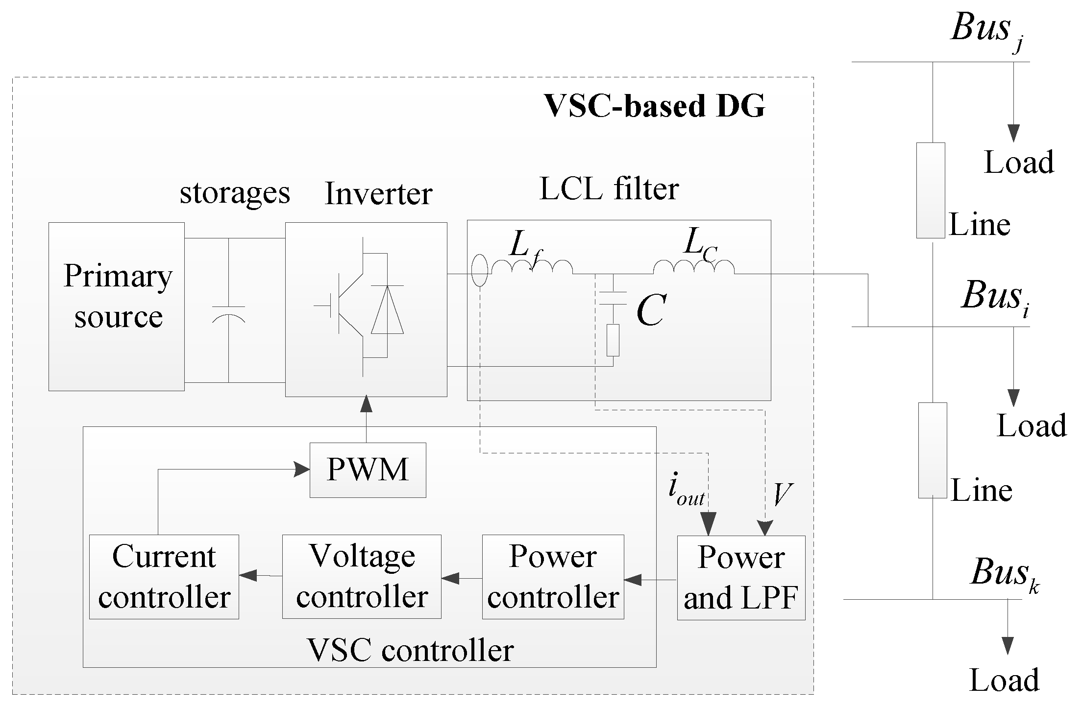
Most of the DGs, including the photovoltaics, wind turbines and battery energy storage systems, are parallel-connected to MG through voltage source converters (VSCs). The typical structure of VSC is given in
Figure 1, which generally is comprised of several parts, such as the power-sharing controller, voltage and current controller, inverter and switching process, output filter, coupling inductance and primary source. The model details of each part are described in [
7,
23], where the DC voltage, which is the input of inverter, is considered fixed. Since the dynamics of the voltage and current controller are much faster than that of the power controller, the combination of inverter, filter, primary sources and energy storages can be considered as a controllable voltage source. In addition, the bandwidth of the inverter voltage controller can be increased using several techniques, as described in [
23]. In this paper, we take an inverter as an ideal voltage source with controllable amplitude and frequency [
24].
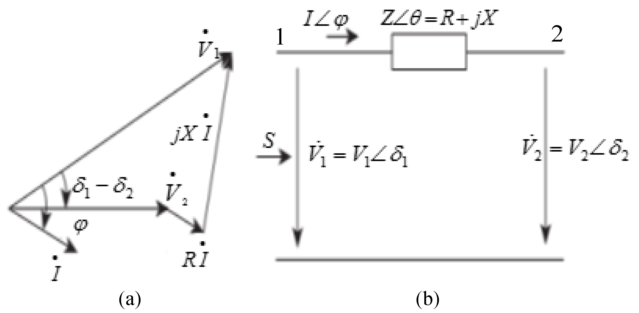
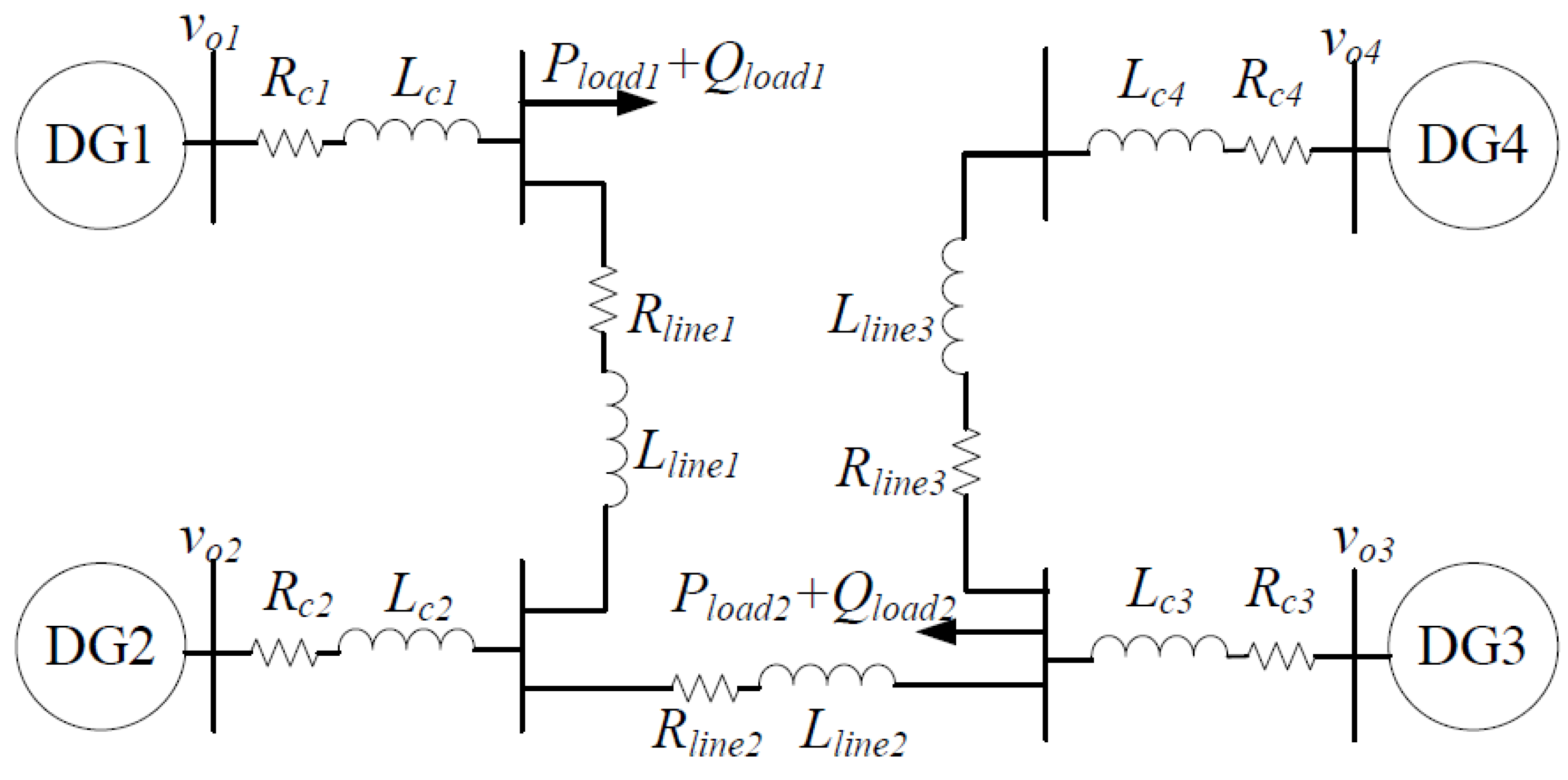
The power flow in MG can be simplified to a two-node system, as shown in
Figure 2, which can be written as
where
and
are the active and reactive power from node 1 to node 2, respectively; and
and
,
are the voltage and phase of the two nodes, respectively. Z and
are the impedance and angle of the transmission line, respectively; R and X is the resistance and inductance, respectively.
From Equation (1), by multiplying
Q by
R and subtracting the product from multiplication of
P and
X, and multiplying
Q by
X and adding the product from multiplication of
P and
R, we can obtain:
When neglecting the line resistance (
i.e.,
R = 0), Equation (2) can be rewritten as
where δ is the power angle,
i.e.,
Therefore, the active and reactive power of DG can be controlled by drooping the frequency and voltage of the power system, respectively:
where
f is the output frequency;
and
are the output voltage in
d-axis and
q-axis, respectively;
,
are the initial frequency and voltage when the output power is 0, respectively; m and n are the droop parameters, respectively;
P and
Q are the active and reactive power of DG, respectively.
Equation (4) presents the primary control of islanded MG. High gain angle droop control ensures proper load sharing, especially under weak system conditions. However, it has a negative impact on overall stability such as small signal stability [
23]. Furthermore, the voltage and frequency error always exist when operating. The secondary control based on the primary control is needed. In islanded MG, because the droop parameters are usually chosen based on the permitted frequency/voltage errors and DGs’ power rating, the purpose of secondary control in islanded MG is to regulate
and
.
By differentiating the primary control characteristic in Equation (4), we can obtain
where
and
are the differential value of frequency and voltage, respectively.
Equations (5) and (6) show the first-order dynamic model of secondary control of islanded MG. The first-order system is a time-delay control system, and only the differential of frequency and voltage can be controlled so that the frequency and voltage are close to the target gradually. Then, the auxiliary variables, by expanding Equations (5) and (6), are used to precisely control the differential, that forms the secondary-order model:
where
and
are the auxiliary control variables of frequency and voltage, respectively. All DGs’ frequency and voltage synchronize to the rated by designing
and
.
Thus, the secondary-order model of MAS-based MG can be written as
where the subscript of
i and
n are the sequence and total number of DGs in islanded MG.
By properly designing the auxiliary variables of
and
, the MG can operate at the rated frequency and voltage. However, it should be noted that once the secondary frequency control is applied, the output active power of DG is distributed according to the same method used for primary control [
23]. After applying the primary control, the active power satisfies the following equation so that the active power of each DG is proportion to its rated value:
In Equation (11), the droop coefficients
mi are set based on the rated active power of DGs
PNi [
23], which is equivalent to
, where
PN is the rated active power.
The secondary-order model of DG agent can be derived by differentiating Equation (11), and using the same expanding method of secondary frequency and voltage control:
where
is the auxiliary control variable of active power control.
Therefore, based on Equation (12), the model of active power allocation of islanded MG can be obtained as follows:
Therefore, the active power allocation among DGs can be realized by designing the auxiliary control variable of .
The combination of Equations (9), (10) and (13) forms the secondary-order MAS model of secondary control for islanded MG.
3. Synergetic Secondary Control of Islanded MG Based on MAS
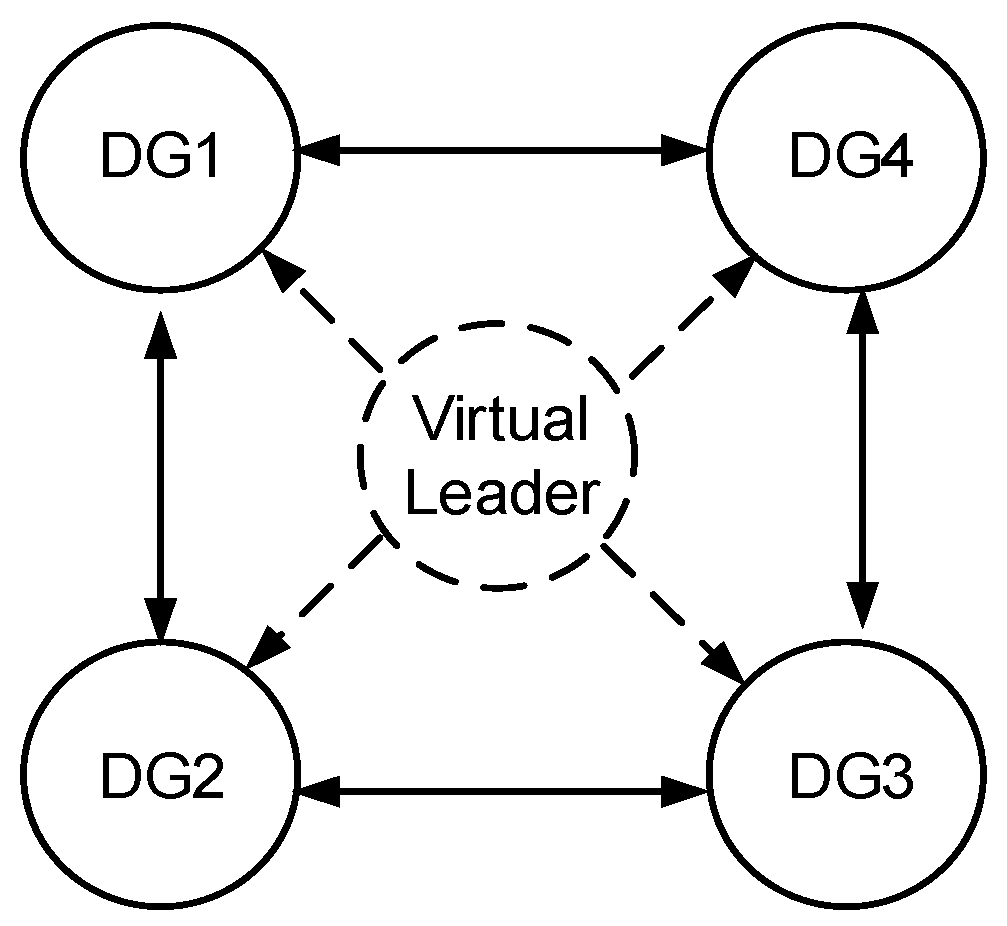
The secondary control of islanded MGs is a tracking synchronization problem, where all DGs try to synchronize their terminal voltage amplitude and frequency to the rated values. In MAS-based MG, all agents seek to synchronize to a virtual leader with the rated frequency and voltage (see
Figure 3). In a distributed synergetic control, each agent needs to exchange the information with its neighboring DGs. In MAS, the spare communication network in MG can be modelled by digraph theorem.
3.1. Graph Theorem
The communication network of MG can be modelled by a digraph [
25]. In MG, a DG is considered as a node of the communication digraph, and the edges of the communication network symbolize the communication links. A digraph is usually expressed as
with a non-empty finite set of N nodes
, a set of edges or arcs
that is the Cartesian product of V, and the associated adjacency matrix
. In this paper, the digraph is assumed to be time-invariant, and then, A is constant. An edge from node j to node i is denoted by
, which means that node i receives the information from node j. In a digraph,
denotes the edge from node i itself, which is usually neglected.
is the weight of edge
, and
if
, otherwise
. Node j is called a neighbor of node i if
. The set of neighbors of node i is denoted as
. In MG, since all DGs exchange information through communication links, the non-directed graph is considered, that node i can receive/send the information from/to node j at the same time. The Laplacian matrix of the digraph is defined as
, where
if
.
3.2. Active Power Control
The active power of DG is allocated according to the droop coefficients used for primary control of islanded MG. Therefore, the active power allocation for secondary control is designed firstly. In this section, the synergetic control is used to design the auxiliary control variables.
To achieve precise power allocation among DGs, it is assumed that DGs communicate with their neighbors through a prescribed communication digraph
. Since the active power of DG can not be predicted, the synergetic control with leaderless is adopted in this paper. The auxiliary controls
are chosen based on the own information of each DG and the information of its neighbors in
Figure 3 as follows:
where
and
are two parts of the auxiliary control
, which are given in Equations (14a,b), respectively. In the synergetic control, the first part is to directly control the active power of DGs to allocate according to the droop control and the last one is to control the errors of
in each DG is to be the same. The non-negative coefficients
are two control gains,
i.e.,
. Moreover,
sign means the signum function,
i.e.,
The solutions of Equation (13) show that the equilibrium point of the control is = 0. Thus, the output active power of DG is allocated in inverse proportion to the droop coefficients. Since the active power allocation is realized, the system stability is also needed to be taken into consideration.
The small signal stability based on the linearization model [
23,
24] and bifurcation method [
26,
27,
28] based on nonlinear analysis method are two common-used methods for MG. In this paper, the extended Lyapunov theorem is adopted to analyze the globally asymptotic stability.
In control system, the behavior of a system about its equilibrium point can be studied by Lyapunov’s stability theorem [
29,
30]. Lyapunov’s stability theorem allows us to determine the stability for the MG system by analyzing an energy function, which is also called as the Lyapunov function
. According to Lyapunov’s direct method, the equilibrium point is globally asymptotically stable if
satisfies the following four properties:
- (1)
- (2)
- (3)
- (4)
To analyze the stability of the active power control in Equation (14), the following Lyapunov function is considered.
Obviously, the first three conditions in Lyapunov’s theorem are always satisfied. Then, only the last condition is needed to analyze.
By differentiating the Lyapunov function in Equation (17), we obtain the following equation:
Then, add the secondary-order MAS model in Equation (13) to Equation (17)
The first and third parts in Equation (18) are always satisfied by the following equation,
i.e.,
Then, Equation (18) can be simplified to
Consider the signum function in Equation (15), we can obtain the result that the control system in Equation (14) satisfies the following function:
Thus, all the conditions of Lyapunov’s theorem are satisfied, i.e., the stability of synergetic control in Equation (14) leads to globally asymptotic stability.
3.3. Secondary Voltage Control
In this section, a distributed synergetic control is designed to control all the voltage magnitudes of DGs
to the reference voltage
. Because the reference of secondary voltage is given at first, a virtual leader with the rated value is set to design the synergetic control. The auxiliary controls
are chosen based on the own information of each DG and the information of its neighbors in
Figure 3 as follows:
where the subscript
L means the virtual leader;
are three parts of the auxiliary control
that are given from Equations (22a) to (22c), respectively. In Equation (22), Equation (22a) is to directly control the DG voltage to work to the same value by using its own and the neighbors’ voltage; Equation (22b) is to control the voltage errors to be the same, and Equation (22c) is to control the DG to synchronize to the virtual leader. The non-negative coefficients of
and
are three control gains,
i.e.,
.
Similarly, we use the following Lyapunov function to analyze the system stability:
According to the analysis results in Equation (16), the above function satisfies the first three conditions in Lyapunov’s theorem. By differentiating Equation (23), we obtain
Then, adding the secondary-order MAS model in Equation (10) to Equation (24), and utilizing the analysis results in Equation (19), we can obtain
Suppose that
. Then, we can obtain
Adding Equations (19) and (26) to Equation (25) yields:
According to the analysis results in Equation (20), the secondary voltage control always satisfies the conditions in Lyapunov’s theorem. Therefore, the synergetic secondary voltage control has globally asymptotic stability.
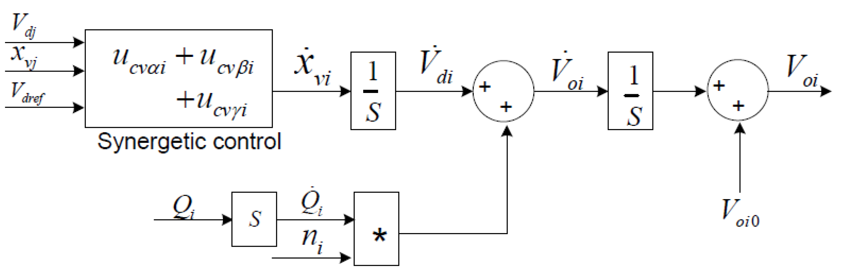
The block diagram of the secondary voltage control based on the distributed synergetic control is shown in
Figure 4. The control input
is
where
is the initial value of
in the primary control, and
is the reactive power in the primary control [
23].
3.4. Secondary Frequency Control
In this section, a distributed synergetic control is designed to control the frequency in each DG to the reference value of
. To complete the target, it is assumed that DGs can communicate with each other through a prescribed communication digraph
. The auxiliary variable
is chosen based on its own information and its neighbors in
Figure 3 as follows:
where
are three parts of the auxiliary control
that are given from Equation (29a) to (29c), respectively. In Equation (29), Equation (29a) is to directly control the frequency to work to the same value by using its own and the neighbors’ information; Equation (29b) is to control the frequency error to be the same, and Equation (29c) is to control the DG to synchronize with the virtual leader. The non-negative coefficients
and
are three control gains,
i.e. .
According to the analysis results in the secondary voltage control, we can obtain that the secondary frequency control in Equation (29) also has globally asymptotic stability. Therefore, the secondary frequency control input
is
where
is the initial value of
in the primary control.
Because the active power of DGs needs to be allocated according to Equation (11), the active power
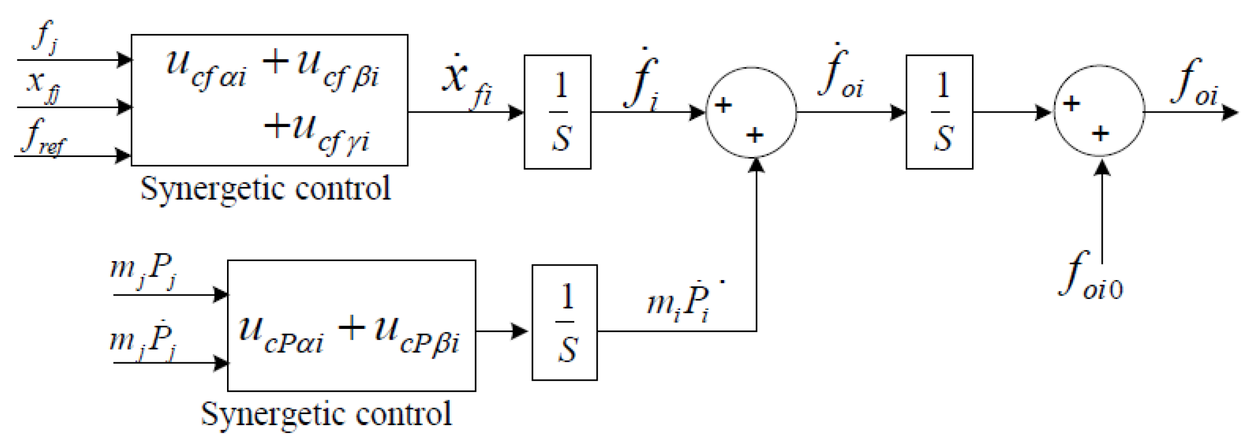
in secondary frequency control is obtained from Equation (14), but not the value calculated from the DG’s output current and voltage. Then, the whole secondary frequency is
Based on the distributed synergetic control, the block diagram of the secondary frequency control is illustrated in
Figure 5.
5. Discussion
As seen in
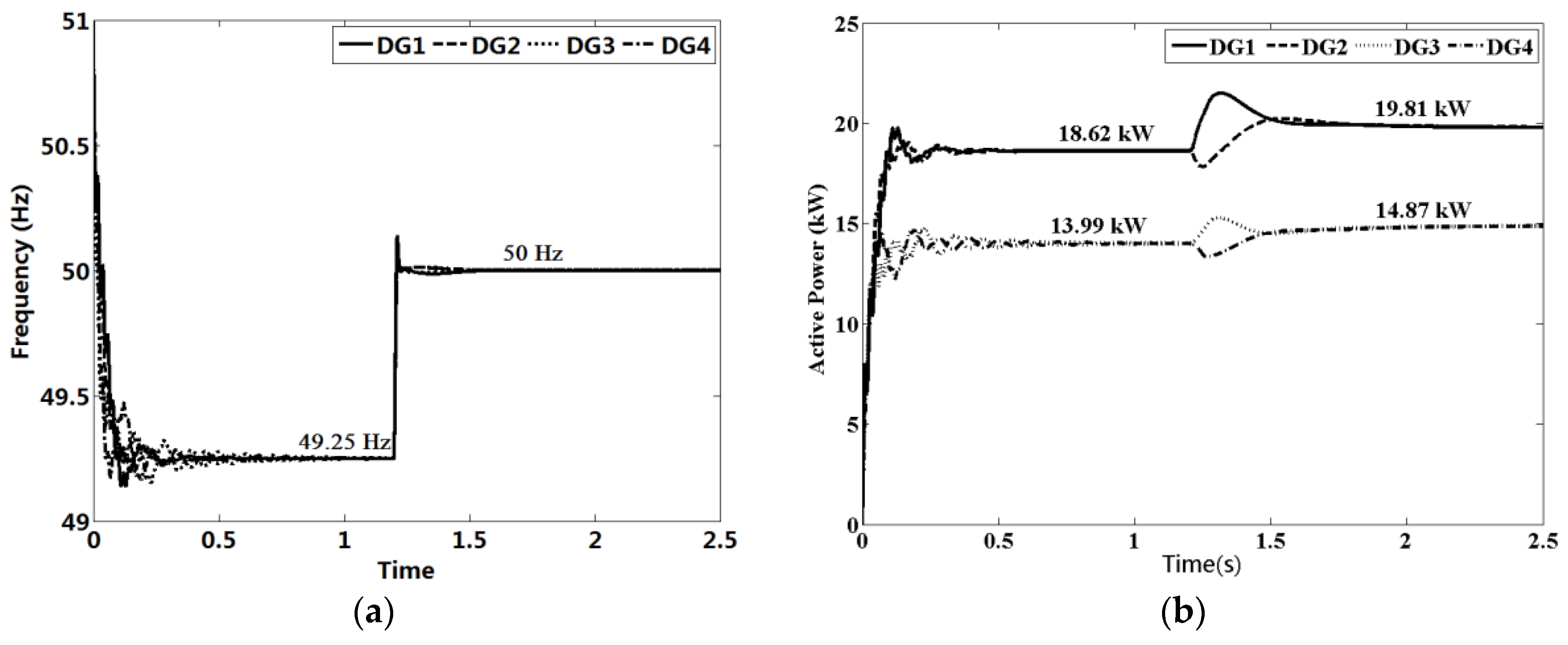
Figure 7, the islanded MG starts to work with primary control and goes to stability state after 0.8 s. In
Figure 7a, the operating frequencies all go to a common value (49.3 Hz) less than the rated, which is the frequency of MG. Due to the primary control, the output active power of the four DGs is allocated according to their droop parameters. After 1.2 s, the secondary frequency control in Equation (31) is applied, and the operating frequency of the islanded MG returns to its rated value after about 0.3 s, shown in
Figure 7a. As seen in
Figure 7b, the output active power of DGs is allocated in inverse proportion to the droop parameters because the distributed active power control in Equation (14) is applied.
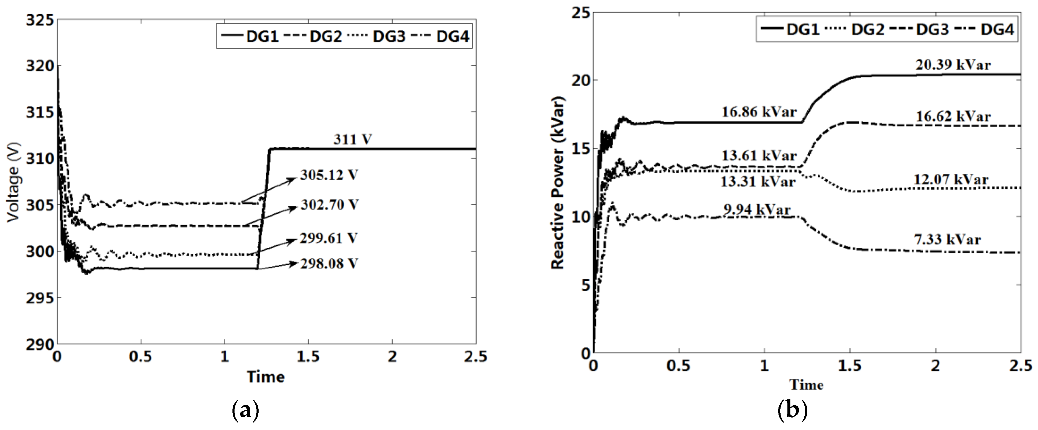
Figure 8 presents the voltage and reactive power of DGs. Similar to the frequency control, the terminal voltages of DGs works with a different value less than the rated
. Once the synergetic secondary control is applied, all the DGs’ voltage
returns to the rated value, as shown in
Figure 8a. Because of the application of primary in Equation (4), the quadratic term of DG voltage is 0. Therefore, the active and reactive power of DGs is re-allocated according to the primary control, which corresponds to the results shown in
Figure 7b and
Figure 8b, respectively.
In power systems, since the system frequency error can be used to measure the active power deviation, the centralized control based on the secondary control in traditional power grid can be used to restore the system frequency, which has been verified in [
9,
10,
11]. However, the system with centralized control may be unstable based on the analysis results in [
23], which is globally asymptotic stability under the proposed control. Meanwhile, the secondary voltage control is very complex through the centralized control for the following reasons. Firstly, the reactive power deviation of the grid cannot be derived directly through the same way because the voltage at each node is not the same. In addition, even though the reactive power deviation is obtained, its allocation is still a complex problem because the power flow is different to the traditional power grid while the balance point of the grid does not exist in droop-controlled MG.


