Article

Asymmetrical Fault Correction for the Sensitive Loads Using a Current Regulated Voltage Source Inverter

1
Department of Electronic Systems Engineering, Hanyang University, Ansan 426-791, Korea
2
Department of Electrical & Computer Engineering, Florida State University, Tallahassee, FL 32310-6046, USA
*
Author to whom correspondence should be addressed.
Energies 2016, 9(3), 196; https://doi.org/10.3390/en9030196
Submission received: 19 January 2016 / Revised: 9 March 2016 / Accepted: 9 March 2016 / Published: 15 March 2016

Abstract

:
Numerous industrial applications involve loads that are very sensitive to electrical supply instabilities. These instances involve various types of voltage imbalances as well as more serious disturbances such as symmetrical and asymmetrical faults. This paper proposes a cost-effective voltage imbalance and asymmetrical fault correction solution for the three phase sensitive loads utilizing an industry-standard current regulated voltage source inverter by connecting it in parallel to the grid mains powering to the sensitive load. The inverter regulates the current for the load and never permits it to go beyond a prescribed value under any type of asymmetrical fault condition, which ensures high power regulating and conditioning capacities. Experimental results are obtained from a small laboratory size prototype to validate the operation of the proposed technique.

1. Introduction

Fault management is a matter of great interest since electrical disturbances can cause a number of serious problems in the electrical transmission and distribution systems as well as for sensitive loads. In general, faults can either be symmetrical or asymmetrical. Symmetrical faults constitute a three phase short circuit, which leads to severe voltage sags. Fortunately, they are rare in power systems. Asymmetrical faults cause voltage sags of a magnitude depending upon the distance between the fault location and the load. In addition, they are much more common in power systems [1,2,3,4]. Since a three phase fault sometimes involves complete interruption of the power flow from the utility, this type of condition can only be effectively dealt with by utilizing an expensive uninterruptible power supply (UPS) system having a separate battery or diesel generator power supply.
Typical examples of industrial applications that demand a tightly regulated power supply include semiconductor processing, electromagnetic compatibility (EMC) testing, electromagnetic interference (EMI) testing and magnetic field generation. The conventional means to deal with this problem is by installing various types of power compensating and conditioning equipment or by providing custom power supply containing dedicated power electronic components [5,6,7,8,9]. While these solutions are effective, they are costly and used only in a few applications. Furthermore, they require a minimum of quarter cycle for the starting of operation, which restricts them to only being adopted in extremely sensitive load applications [10]. In addition, since most of the power conditioning and regulating devices are voltage controlled, they come up with performance issues while powering nonlinear loads.
A much less expensive solution with power regulating and conditioning capabilities is possible if protection against any of the fault conditions other than a three phase fault is considered adequate. This paper proposes a lower cost solution to this problem, in which a conventional cost-minimized rectifier/inverter normally utilized as the electrical supply for a variable frequency AC motor load is used to regulate power for the sensitive load.
In the proposed system, the inverter is always physically connected to the load and can thus react almost instantly to a disturbance in the power supply. The sole responsibility of the inverter is to keep three phase load currents constant and balanced. If the power system experiences any type of asymmetrical fault or suffers from a source voltage imbalance, the power is then balanced by a current regulated voltage source inverter using recently developed variable frequency motor control [11,12]. However, they are also ideally suitable to directly controlling AC currents with any balanced load, with or without an associated EMF (i.e., motor load). Although the asymmetrical fault causes a disturbance to the DC voltage link of the power converter of the proposed system, it is shown that this effect can be effectively eliminated by tight regulation of the inverter current. Thus, the possibility of damage to the system equipment, consumer’s critical loads and the interruption of service to a consumer can be eliminated during the vast majority of fault conditions.

2. Causes, Effects and Existing Solutions of Asymmetrical Faults

Weather conditions, tree branches, human or animal contacts and insulation failure can generate symmetrical as well as asymmetrical faults. Relatively few loads, close to the fault location will go through the worst possible fault condition and often experience a sag close to zero followed by an interruption due the operation of circuit breakers installed at the utility side. However, the majority of loads, which are, generally, away from the fault location, will experience a sag of a magnitude depending upon the distance between the load and fault location, and the duration required for the operation of the protection devices and schemes installed at the utility side [13]. The magnitude of these sags is always lower than those close to the fault location. To investigate the effect of the asymmetrical fault on a sensitive load, simulations have been performed during the worst possible fault condition for the load (i.e., close to the fault point F), using a passive grounded load of 500 VA. For generalization, the load currents are assumed to be in per unit (p.u) system here. During such loading and operational conditions, when a phase A, undergoes a single-line-to-ground (S-L-G) fault the phase currents for the load will be:
Ia = 0 and Ib = Ic = 1 (p.u)
Similarly, when two phases, A and B, simultaneously experience a ground fault, i.e., double-line-to-ground (D-L-G), the phase currents for the load will be:
Ia = Ib = 0 and Ic = 1 (p.u)
However, in the case of a single-line-to-line (S-L-L) fault between the two phases, A and B, the relations for the phase currents of the load will be:
Ia = − Ib and Ic = 1 (p.u)
Figure 1a–c show the simulations results for the load currents when a load experiences a single line-to-ground, double-line-to-ground and line-to-line faults, respectively.
Statistical data have shown that sags decreasing the nominal line voltage to 40%–50% and lasting for less than 2 s results in about 92% of the total interruptions encountered by the industrial applications [14]. These interruptions cause significant financial loss, depending on the nature of the application. A semiconductor facility could suffer up to USD 1 million in losses per voltage sag event if it processes 200 mm wafers [15].
The conventional means for industrial consumers to deal with asymmetrical faults and to avoid substantial financial losses is to install various types of power regulating and conditioning devices (for example, series voltage sag compensator, isolated parallel voltage sag compensator, spike suppressor, voltage regulator, transformerless dynamic series compensator, etc.) within the sensitive load applications. Some of these devices require transformers for the electrical isolation purpose, which increases the overall size, cost, and weight of the system and hence, makes them unfavorable to be installed within domestic and industrial applications. However, most of them require a time interval (around a quarter cycle) to detect the fault and to start power regulating functions. Though this time interval does not affect most of the applications, but can cause serious malfunction problems for critical loads, such as for semiconductor processing, EMC and EMI testing, magnetic field generation, etc. Furthermore, since these devices are voltage controlled, they have some performance issues when dealing with nonlinear loads. Some equipment in the market with internal energy storage, like online UPS systems, has been designed to encounter the voltage sag effects for the sensitive loads with the best power regulating and compensating capabilities. However, their low efficiency, and high acquisition and operational costs rule them out broadly for noncritical industrial and commercial applications [16,17].

3. Proposed Asymmetrical Fault Correction Technique

The proposed asymmetrical fault correction technique for the sensitive loads is based upon following principles:
  • It should provide protection to sensitive loads during all types of asymmetrical faults occurring, whether near or far from the fault point/location.
  • The control scheme should be based on a current regulation algorithm to avoid performance issues while dealing with a large number of nonlinear loads for industrial use.
  • The proposed topology should be economical, with an instant response to ensure high power regulating and conditioning capabilities and to make it feasible for all sensitive load applications.

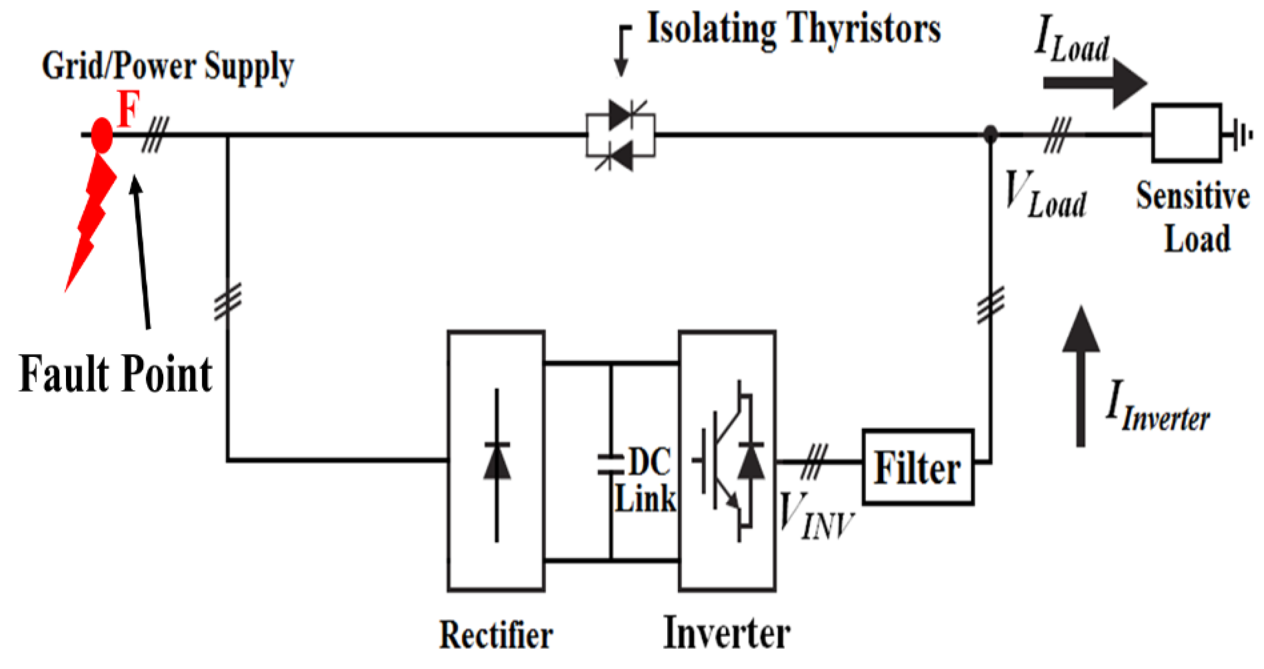
3.1. Operating Principle

A simple diagram of the proposed asymmetrical fault correction technique is shown in Figure 2. However, Figure 3 shows a complete diagram of the proposed technique. In the circuit shown in Figure 3, a typical current regulated voltage source inverter is connected in parallel to the utility mains feeding the sensitive load. The proposed system is also equipped with an isolating thyristor bank (or contactors). During normal operation, the sensitive load is supplied power by the grid/power supply and the load currents are monitored throughout. Meanwhile, the DC link capacitor is charged through charger/rectifier. During any sag that causes the load current to collapse to 1%~50% of the rated load current, the inverter instantly injects the difference between the rated load and the utility currents without employing the isolating thyristors. However, during any S-L-G, D-L-G, and/or S-L-L faults that causes one or two of the phases decrease to 50% of the rated phase current, the isolating thyristor bank becomes activated to isolate the faulty phase from the load and the inverter instantly supplies the faulty phase current to the load, to keep the load current constant throughout the fault duration. Since the proposed system is for critical applications that require constant currents, the reference currents are fixed for any particular load application. If the load is changed, the reference currents can be adjusted accordingly. This can be done using an outer voltage loop. Under such condition, the controlled error signal of the voltage loop generates the reference for the inner current loop. This enables the proposed asymmetrical fault correction technique to correct the sags for any loading condition, regardless of the distance between the load and the location of the fault.

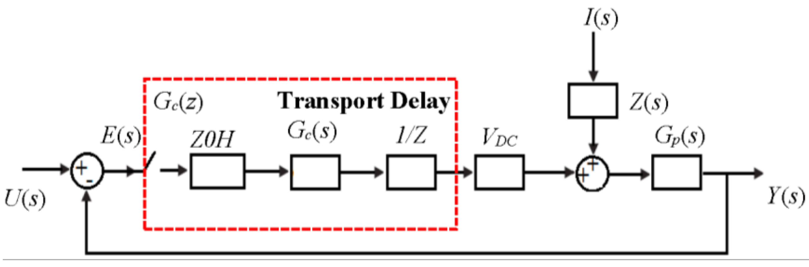
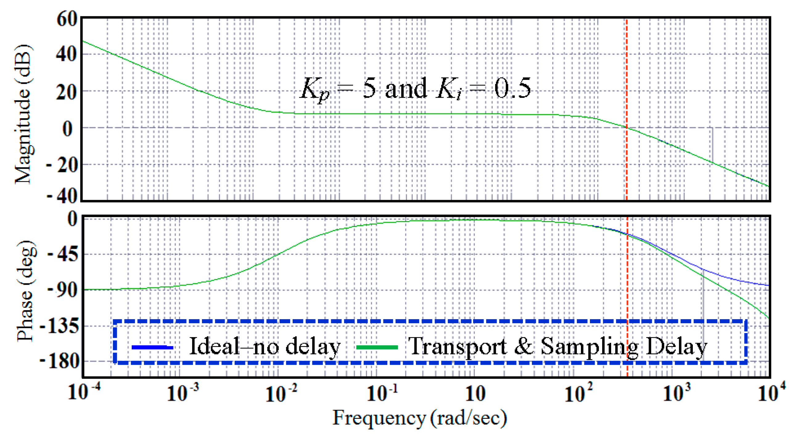
3.2. Current Regulating Algorithm

Current regulation for the proposed asymmetrical fault correction technique is achieved through a PI regulator implemented in the stationary frame of reference as discussed in [18]. Figure 4 shows an “average value model” block diagram of the inverter of proposed fault correction technique. In the given diagram, U(s) is the rated load current, E(s) is the error of feedback and rated load currents, and VDC is the forward gain of a linear amplifier, which replaces the PWM modulator. The grid input current is modeled as a current injection I(s), and Y(s) is the required output current of the inverter to obtain the regulated current for the load.
The transfer function of the current regulated voltage source inverter is given by:
Y ( s ) = U ( s ) × G c ( s ) × V D C × G p ( s ) 1 + G c ( s ) × V D C × G p ( s ) + I ( s ) × Z ( s ) × G c ( s ) 1 + G c ( s ) × V D C × G p ( s )
The function of the controller Gc(s) in this system is to match the output currents Y(s) to the rated load currents U(s) as close as possible. Circuit theory yields an R/L “plant” transfer function of:
G p ( s ) = 1 R ( 1 + s T ) ,   T = L / R
The transfer function of load impedance Z(s) is:
Z ( s ) = R ( s ) + s L ( s )
where R(s) is the load resistance and L(s) is the load inductance.
Gc(s) is the transfer function of the PI regulator and is given by:
G c ( s ) = K p ( 1 + 1 s τ r )
where τr is the ratio of the proportional and integral gains (Kp/Ki).
The Open Loop Forward Path Gain of the proposed system is:
G p G c ( s ) = G p ( s ) × V D C × G c ( s )
By substituting Equations (5) and (7) into (8), the Open Loop Forward Path Gain of the proposed system will be:
G p G c ( s ) = V D C × K P R × τ r × 1 + s τ r s ( 1 + s T )
which is a second order system and has a phase response that is an asymptote of −90° at high frequencies [19,20].
The total transport and sampling delay for the implemented current-regulating algorithm for the inverter is about 0.75 of the carrier period. The control loop delays can be modeled using Z-transform theory [21,22] with a zero-order-hold (ZOH) element to model sampling delay and a 1/Z block in series with the controller to model transport delay. Figure 5 shows a Bode plot of the Open Loop Forward Path Gain of the implemented current control algorithm, with the effects of transport and sampling delays included.

3.3. Advantages of the Proposed Technique over Existing Solutions

The advantages of the proposed asymmetrical fault correction fault correction technique are discussed in terms of protecting, power conditioning and regulating capabilities. A detailed comparison on the basis of protection capability for various power conditioning equipment is given in [23]. However, this paper includes the comparison of the proposed fault correcting system with the conventional power conditioning systems mentioned in [23], as shown in Table 1. In the comparison, it is shown that the proposed fault correction technique solves most of the power quality issues, except interruptions between 0.15 and 500 s and outages greater than 500 s. This is due to the energy storage limitations of the DC link. However, since the proposed technique is based on current control algorithm, it offers better performance when dealing with nonlinear loads. Since an online UPS system provides the best power conditioning and regulating capabilities, a detailed comparative analysis of the proposed technique and the online UPS system is carried out (Table 2). This table shows that the primary powering path for an online UPS system is inverter; however, the proposed fault correction technique uses utility in this regards. The efficiency of an online UPS system is lower than the proposed technique. This is because the operation of an online UPS system involves double conversion of power, i.e., AC/DC and DC/AC, which increases the overall capacity of the system to 210% of the rated power (100% for the inverter and 110% for the rectifier since it powers the DC link as well as the inverter simultaneously) [24]. However, the overall power capacity of the proposed system is around 110% (100% for the inverter and 10% for the rectifier since it only charges the DC link of the inverter). The size, cost and weight of an online UPS system are also higher than the proposed system.

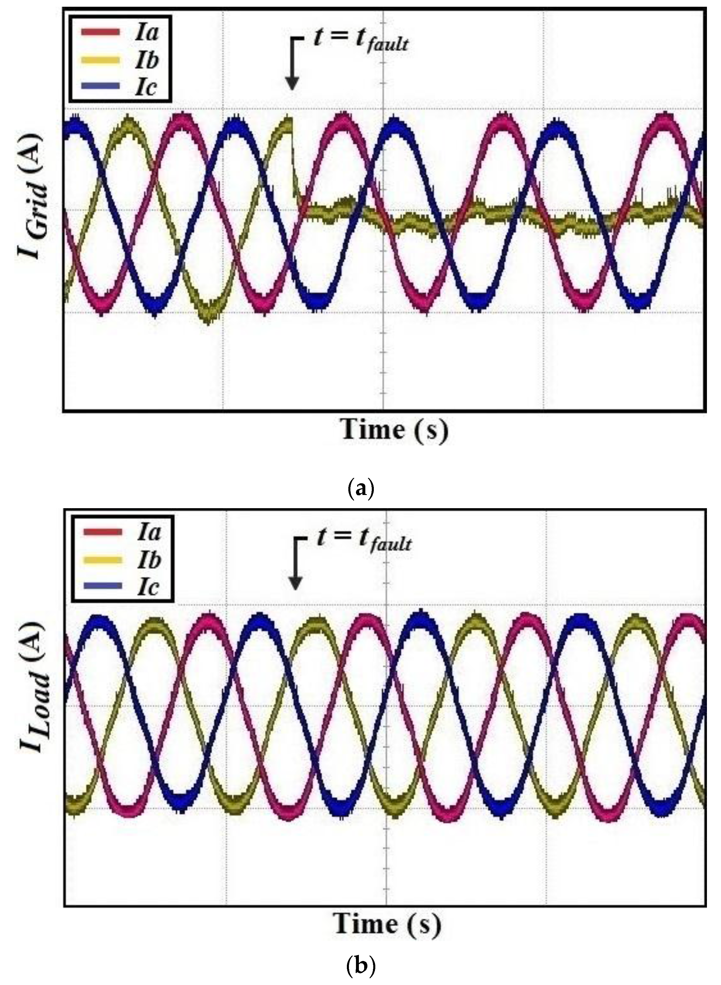
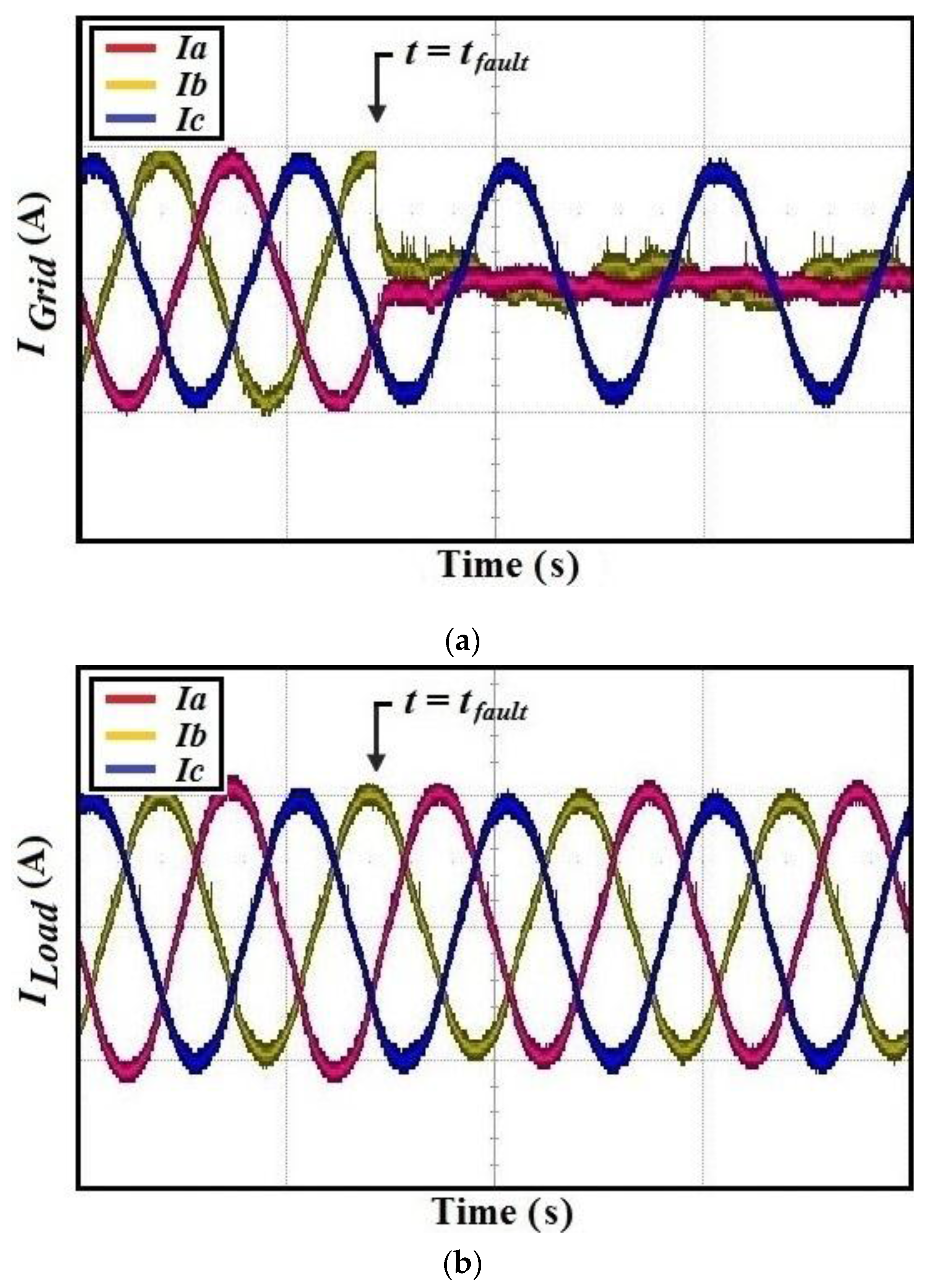
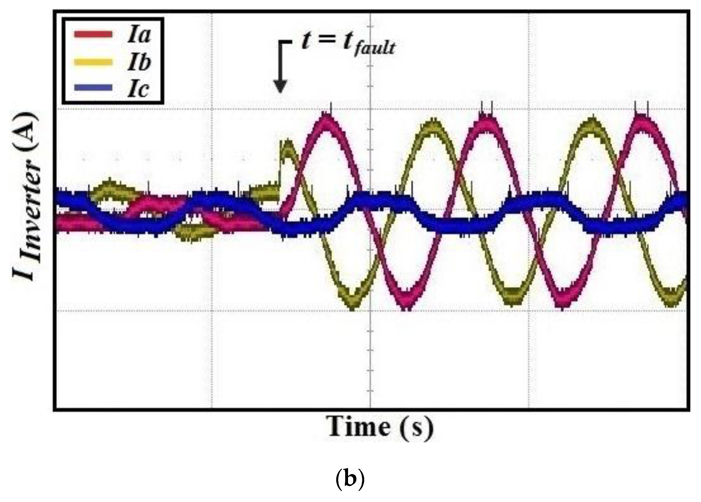
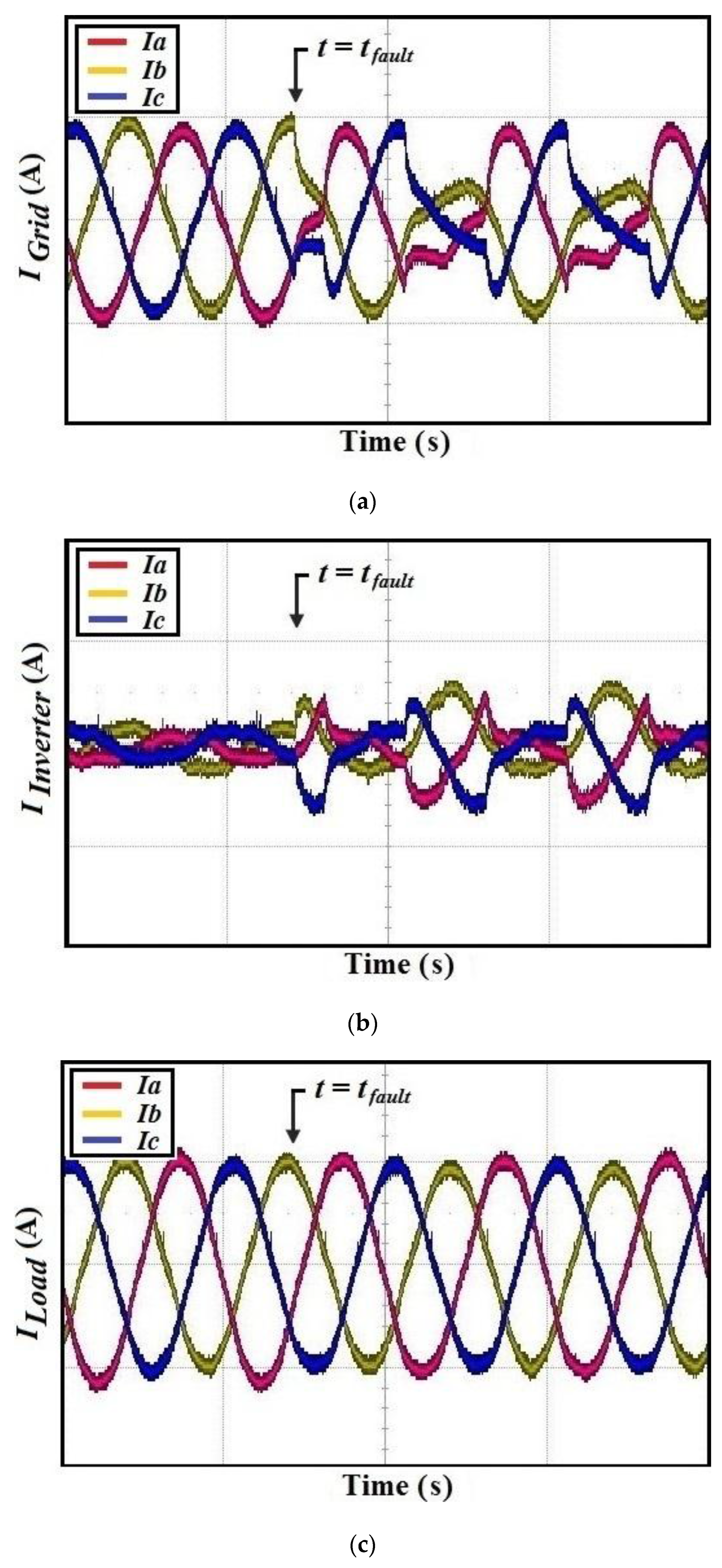
4. Experimental Results

To validate the proposed fault correction technique for sensitive loads, a small prototype of the system in Figure 2 and Figure 3 has been constructed. The system parameters are given in Table 3.
The hardware for the proposed asymmetrical fault correction technique for sensitive loads consists of three major parts: a digital signal processor (DSP) controller for implementing the control requirements for the inverter of the proposed system, power components to handle the power flow, and an RL load. A DSP processor TMS320F28335 from Texas instruments with external clock of 150 MHz is used for processing the data. A 12-bit ADC channel from this DSP controller has been used to sample the load current signals coming from the current sensors. A carrier frequency of 10 kHz is used to generate pulse width modulation (PWM) signals. A PI regulator having proportional (Kp) and integral (Ki) gains of 5 and 0.5, respectively, is programmed. The controller is implemented in a stationary frame of reference using a DSP processor to regulate the load current during any asymmetrical fault condition.
The experimental results of the proposed fault correction technique are discussed with the following conventions labeled on the figures:
ILoad, Load current;
IGrid, Power supply/Grid current; and
IInverter, Inverter current.
During normal operation, the load is supplied current from the grid and the DC link capacitor is charged through the rectifier. At a particular moment, say t = tfault, an asymmetrical fault is assumed to occur at the utility side and the isolating thyristor bank becomes activated to isolate the faulty phase from the load. Meanwhile, the inverter instantly supplies the faulty phase current to the load to keep the load current (ILoad) constant. Figure 6a shows the experimental results for the grid/power supply currents (IGrid) after the isolation of faulty phase, when the grid suffers a S-L-G fault. Figure 6b shows the constant and balanced load current obtained during such a condition using the proposed fault correction technique. Experimental waveforms for the grid (IGrid) and load currents (ILoad) during D-L-G and S-L-L faults are shown in Figure 7a,b. However, the inverter response during S-L-G, and D-L-G and S-L-L faults is shown in Figure 8a,b.
From the given experimental results, it can be seen that the load currents with the proposed fault correction technique are balanced and constant if the power supply goes through any of the above-mentioned asymmetrical faults. These experimental results are obtained when the sensitive load is operating near the fault location i.e., worst fault condition. Since the majority of loads operate far from the fault location and experience voltage sags of different magnitude, experimental results have been obtained during a sag for 8 ms in order to investigate the operation and performance of the proposed fault correction technique. Figure 9a shows the experimental waveforms of the grid current (IGrid) showing that when t = tfault, the grid undergoes a fault and starts supplying a sag for 8 ms after every half cycle. During such a condition, the inverter instantly supplies the supplementary current for the same interval to the load to keep the load current constant. This results in a seamless compensation of load currents. Figure 9b,c show the inverter and load currents. While operating with the proposed faults correction technique, the DC link voltage of the power converter also undergoes disturbances, caused by the asymmetrical faults at the grid side. However, this effect is effectively eliminated by tight regulation of the inverter current. Figure 10a–c show the change in the DC link voltage during such faults. Since the holdup time of the proposed system against the instabilities is utterly dependent on the size of the critical load and the energy storage capability of the system, important consideration should be given to the DC link capacitance of the system before installing the proposed system along with a sensitive load of specific rating [25]. The compensation energy, power, and the DC link capacitance can be expressed as follows:
E = 1 2 C D C ( V d c 2 D C V 2 G r i d _ p e a k ) [ J ]
P = C D C ( V d c 2 D C V 2 G r i d _ p e a k ) 2 T [ W ]
C D C = P T 0.5 ( V d c 2 D C V 2 G r i d _ p e a k ) [ F ]
where T is the compensation time [26].

5. Conclusions

A solution to the problem associated with asymmetrical faults and imbalances has been discussed in this paper. This paper proposes that, by integrating a standard current regulated voltage source inverter in parallel to the load and utility mains, any of the asymmetrical fault or imbalance can be avoided for sensitive loads.
The proposed technique avoids interruption of the power supply during the faults and provides instant protection to critical loads with high power regulating and conditioning capabilities. Furthermore, since the proposed fault correction technique is based upon current regulating algorithm, it will offer better performance compared to the typical sag correction techniques while dealing with nonlinear loads. In addition, the proposed technique requires only a typical, standard inverter normally utilized as the electrical supply for a variable frequency AC motor load, which makes it economical for sensitive load applications that do not warrant the use of a custom power supply.

Acknowledgments

This research was jointly supported by the “BK21PLUS program” through the National Research Foundation of Korea funded by the Ministry of Education and the “Human Resources Program” in Energy Technology of the Korea Institute of Energy Technology Evaluation and Planning (KETEP), granted financial resource from the Ministry of Trade, Industry and Energy, Republic of Korea (20154030200730).

Author Contributions

Thomas A. Lipo proposed the idea, Syed Sabir Hussain Bukhari implemented it by simulations and wrote the manuscript, Shahid Atiq performed the experiment and Byung-il Kwon supervised the research throughout.

Conflicts of Interest

The authors declare no conflict of interest.

References

  1. Beiza, J.; Hosseinian, S.H.; Vahidi, B. Fault type estimation in power systems. Iran. J. Electr. Electron. Eng. 2009, 5, 185–195. [Google Scholar]
  2. Weischedel, H.R.; Westerman, G.R. A symmetry correcting pulse width modulator for power conditioning applications. IEEE Trans. Ind. Appl. 1973, IA-9, 318–322. [Google Scholar] [CrossRef]
  3. Lin, W.M.; Ou, T.C. Unbalanced distribution network fault analysis with hybrid compensation. IET Gener. Transm. Distrib. 2011, 5, 92–100. [Google Scholar] [CrossRef]
  4. Ou, T.C. A novel unsymmetrical faults analysis for microgrid distribution systems. Int. J. Electr. Power Energy Syst. 2012, 43, 1017–1024. [Google Scholar] [CrossRef]
  5. Reed, G.F.; Croasdaile, T.R.; Paserba, J.J.; Williams, R.M.; Takeda, M.; Jochi, S.; Morishima, N.; Aritsuka, T.; Hamasaki, Y.; Yonehata, Y.; et al. Applications of voltage source inverter (VSI) based technology for FACTS and custom power installations. In Proceedings of the International Conference on Power System Technology, Perth, Australia, 4–7 December 2000; Volume 1, pp. 381–386.
  6. Ou, T.C. Ground fault current analysis with a direct building algorithm for microgrid distribution. Int. J. Electr. Power Energy Syst. 2013, 53, 867–875. [Google Scholar] [CrossRef]
  7. Lin, W.M.; Lu, K.H.; Ou, T.C. Design of a novel intelligent damping controller for unified power flow controller in power system connected offshore power applications. IET Gener. Transm. Distrib. 2015, 9, 1708–1717. [Google Scholar] [CrossRef]
  8. Ou, T.C.; Hong, C.M. Dynamic operation and control of microgrid hybrid power systems. Energy 2014, 66, 314–323. [Google Scholar] [CrossRef]
  9. Mirzai, M.A.; Afzalian, A.A. A novel fault-locator system; algorithm, principle and practical implementation. IEEE Trans. Power Deliv. 2010, 25, 35–46. [Google Scholar]
  10. Stump, M.D.; Keane, G.J.; Leong, F.K.S. The role of custom power products in enhancing power quality at industrial facilities. In Proceedings of the International Conference on EMPD, Singapore, 3–5 March 1998; Volume 2, pp. 507–517.
  11. Bukhari, S.S.H.; Atiq, S.; Kwon, B. An inrush current elimination technique for a voltage sag compensator while powering transformer-coupled loads. In Proceedings of the 2015 IEEE Energy Conversion Congress and Exposition (ECCE), Montreal, QC, Canada, 20–24 September 2015; pp. 2710–2714.
  12. Veltman, A.; Pulle, D.W.J.; DeDoncker, R. Advanced Electrical Drives; Springer Verlag: Heidelberg, Germany, 2011. [Google Scholar]
  13. Bukhari, S.S.H.; Kwon, B.-I.; Lipo, T.A. Unsymmetrical fault correction for sensitive loads utilizing a current regulated inverter. In Proceedings of the 29th Annual IEEE Applied Power Electronics Conference and Exposition (APEC), Fort worth, TX, USA, 16–20 March 2014; pp. 366–370.
  14. McGranaghan, M.F.; Mueller, D.R.; Samotyj, M.J. Voltage sags in industrial systems. IEEE Trans. Ind. Appl. 1993, 29, 397–403. [Google Scholar] [CrossRef]
  15. Sabin, D. An Assessment of Distribution System Power Quality; EPRI Final Report TR-106249-V2; Electric Power Research Institute: Palo Alto, CA, USA, 1996; Volume 2. [Google Scholar]
  16. Cheng, P.T.; Chen, W.-T.; Chen, Y.-H.; Ni, C.-L.; Lin, J. A transformer inrush mitigation method for series voltage sag compensators. IEEE Trans. Power Electron. 2007, 22, 1890–1899. [Google Scholar] [CrossRef]
  17. Yeh, C.-C.; Manjrekar, M.D. A reconfigurable uninterruptible power supply system for multiple power quality applications. IEEE Trans. Power Electron. 2007, 22, 1361–1372. [Google Scholar] [CrossRef]
  18. Bukhari, S.S.H.; Atiq, S.; Lipo, T.A.; Kwon, B.-I. Line-interactive UPS system that eliminates inrush current phenomenon. Electr. Power Compon. Syst. 2016, in press. [Google Scholar]
  19. Kong, W.Y.; Holmes, D.G.; McGrath, B.P. Improved stationary frame AC current regulation using feedforward compensation of the load EMF. In Proceedings of the Twenty-Fourth Annual IEEE Applied Power Electronics Conference and Exposition (APEC), Washington, DC, USA, 15–19 February 2009; pp. 145–151.
  20. Bukhari, S.S.H.; Atiq, S.; Kwon, B.-I. Elimination of the inrush current phenomenon associated with single-phase offline UPS systems. Energies 2016, 9, 96. [Google Scholar] [CrossRef]
  21. Franklin, G.F.; Powell, J.D.; Workman, M.L. Digital Control of Dynamic Systems, 3rd ed.; Addison-Wesley: Menlo Park, CA, USA, 1998. [Google Scholar]
  22. Bukhari, S.S.H.; Atiq, S.; Lipo, T.A.; Kwon, B.-I. A cost-effective, single-phase line-interactive UPS system that eliminates inrush current phenomenon for transformer-coupled loads. J. Electr. Eng. Technol. JEET 2016, 11. [Google Scholar] [CrossRef]
  23. Brumsickle, W.E.; Schneider, R.S.; Luckjiff, G.A.; Divan, D.M.; Mcgranaghan, M.F. Dynamic sag correctors: Cost-effective industrial power line conditioning. IEEE Trans. Ind. Appl. 2001, 37, 212–217. [Google Scholar] [CrossRef]
  24. Kim, H.S.; Ji, J.-K.; Kim, J.-H.; Sul, S.-K.; Kim, K.-H. Novel topology of a line interactive UPS using PQR instantaneous power theory. In Proceedings of the 39th IEEE IAS Annual Meeting in Industry Applications Conference, Washington, DC, USA, 3–7 October 2004; pp. 2232–2238.
  25. Ou, T.C.; Chuang, S.J.; Hong, C.M.; Wu, R.C.; Tsao, T.P.; Chen, C.Y. Self-regulation ground faults model for microgrid distribution. ICIC Express Lett. Part B Appl. 2015, 6, 3225–3230. [Google Scholar]
  26. Lee, W.-C. Cost-effective APF/UPS system with seamless mode transfer. J. Electr. Eng. Technol. JEET 2015, 10, 195–204. [Google Scholar] [CrossRef]
Figure 1. Load currents during: (a) single-line-to-ground (S-L-G), (b) double-line-to-ground (D-L-G), (c) single-line-to-line (S-L-L) faults (X-axis: 0.01 s/div; Y-axis: 0.5 p.u/div).
Energies 09 00196 g001
Figure 2. Simple diagram of the proposed asymmetrical fault correction technique for sensitive loads.
Energies 09 00196 g002
Figure 3. Complete diagram of the proposed asymmetrical fault correction technique for a sensitive load.
Energies 09 00196 g003
Figure 4. Average value model block diagram of the proposed asymmetrical fault correction technique.
Energies 09 00196 g004
Figure 5. Bode plot of Open Loop Forward Path Gain for implemented controller with effects of transport and sampling delays.
Energies 09 00196 g005
Figure 6. Experimental waveforms of the: (a) grid currents (IGrid); and (b) load currents (ILoad) with the proposed asymmetrical fault correction technique during a S-L-G fault (X-axis: 20 ms/div; Y-axis: 1 A/div).
Energies 09 00196 g006
Figure 7. Experimental waveforms of the: (a) grid currents (IGrid); and (b) load currents (ILoad) with the proposed asymmetrical fault correction technique during S-L-L and D-L-G faults (X-axis: 20 ms/div; Y-axis: 1 A/div).
Energies 09 00196 g007
Figure 8. Experimental waveforms of inverter currents (IInverter) with the proposed asymmetrical fault correction technique during: (a) S-L-G; (b) S-L-L; and D-L-G faults (X-axis: 20 ms/div; Y-axis: 1 A/div).
Energies 09 00196 g008aEnergies 09 00196 g008b
Figure 9. Experimental waveforms of: (a) grid currents (IGrid); (b) inverter currents (IInverter); and (c) load currents (ILoad) with the proposed asymmetrical fault correction technique during a sag for 8 ms after every half cycle (X-axis: 20 ms/div; Y-axis: 1 A/div).
Energies 09 00196 g009
Figure 10. DC link voltage (V) when the grid experiences: (a) S-L-G; (b) S-L-L; and (c) D-L-G faults (X-axis: 0.1 s/div; Y-axis: 5 V/div).
Energies 09 00196 g010
Table 1. Comparison of various conventional power conditioning equipment mentioned in [23] and proposed technique.
Type of EventSpike SuppressorVoltage RegulatorTransformerless Dynamic Series Compensator (DySC)UPS SystemsProposed System
Spikes and SurgesSolvesSolvesSolvesSolvesSolves
Sag to 80%NoSolvesSolvesSolvesSolves
Sag from 50%–80%NoNoSolvesSolvesSolves
Interruption 0–0.15 sNoNoSolvesSolvesSolves
Interruption 0.15–500 sNoNoNoSolvesNo
Outage > 500 sNoNoNoNoNo
Table 2. Comparison of the proposed fault correction technique and an online UPS system.
AttributesOn-Line UPS SystemProposed System
Primary Powering PathInverterGrid
EfficiencyLowerHigh
Power Regulating and Compensation CapabilitiesYesYes
Cost, Size and WeightHigherLower
System Starting TimeZeroNegligible
Table 3. System parameters.
ParameterValue
Utility/Grid220 V, 50 Hz
DC Bus Voltage365 V
Switching Frequency (fs)10 kHz
Load Resistance160 Ω
Load Inductance21.5 mH
Filter Inductance (Lf)0.265 mH

