Article

Numerical Analysis on Combustion Characteristic of Leaf Spring Rotary Engine

School of Mechanical Engineering, Beijing Institute of Technology, Beijing 100081, China
*
Author to whom correspondence should be addressed.
Energies 2015, 8(8), 8086-8109; https://doi.org/10.3390/en8088086
Submission received: 19 March 2015 / Revised: 12 July 2015 / Accepted: 17 July 2015 / Published: 4 August 2015
(This article belongs to the Special Issue Electrical Power and Energy Systems for Transportation Applications)

Abstract

:
The purpose of this paper is to investigate combustion characteristics for rotary engine via numerical studies. A 3D numerical model was developed to study the influence of several operative parameters on combustion characteristics. A novel rotary engine called, “Leaf Spring Rotary Engine”, was used to illustrate the structure and principle of the engine. The aims are to (1) improve the understanding of combustion process, and (2) quantify the influence of rotational speed, excess air ratio, initial pressure and temperature on combustion characteristics. The chamber space changed with crankshaft rotation. Due to the complexity of chamber volume, an equivalent modeling method was presented to simulate the chamber space variation. The numerical simulations were performed by solving the incompressible, multiphase Unsteady Reynolds-Averaged Navier–Stokes Equations via the commercial code FLUENT using a transport equation-based combustion model; a realizable κ ω turbulence model and finite-rate/eddy-dissipation model were used to account for the effect of local factors on the combustion characteristics.

1. Introduction

This paper introduces a novel rotary engine, “Leaf Spring Rotary Engine”. The leaf spring rotary engine is a pistonless design based on the Wankel engine. A pistonless rotary engine is an internal combustion engine that does not use pistons in the way a reciprocating engine does, but instead uses one or more rotors, sometimes called rotary pistons. An example of a pistonless rotary engine is the Wankel engine. The basic concept of a (pistonless) rotary engine avoids the reciprocating motion of the piston with its inherent vibration and rotational-speed-related mechanical stress. As of 2006, the Wankel engine is the only successful pistonless rotary engine, but many similar concepts have been proposed and are under various stages of development. A Hamilton Walker prototype engine was construction in 1968 [1,2]. Walker’s engine is believed to be the second working rotary engine after the Wankel engine. The Quasitubine, or Qurbine, engine is a proposed pistonless rotary engine using a rhomboidal rotor whose sides are hinged at the vertices in 1996. As well as an internal combustion engine, the Quasitubine has been proposed as a possible pump design, and a possible stirling engine [3]. It has been demonstrated as a pneumatic engine using stored compressed air, and as a steam engine [4]. The essential concept, the Ramgen engine, is the incorporation of one or more ramjets onto the rim of a rotor such that the thrust from the ramjets acts tangentially, causing it to rotate at supersonic ram speeds. The engine is based on ramjet technology, which produces propulsive force by increasing the momentum of the working fluid via combustion and expansion through a supersonic nozzle [5]. The Rotary Piston Machine (RKM) is a proposed form of machine. It can be used either to transform pressure into rotational motion or the converse rotational motion into pressure. It is still in development and offers very high potential in pump market [6]. One application for RKM is miniaturization, like Wankel engine. The Sarich orbital engine is a type of internal combustion engine, invented in 1972 by Ralph Sarich. The theoretical advantage is that there is no high-speed contact area with the engine walls, unlike in the Wankel engine in which edge wear is a problem. However, the combustion chambers are divided by blades, which do have contact with both the walls and the rotor, and are said to have been difficult to seal due to the perpendicular intersection with the moving impeller. A wave disk engine is a type of pistonless rotary engine being developed at Michigan State University and Warsaw Institute of Technology. The engine has a spinning disk with curved blades. Once fuel and air enter the engine, the rotation of the disk creates shockwaves that compress the mixture. The Wave Disk Micro-Engine concept has also been developed [7]. The Jonova engine is a type of pistonless rotary engine designed by Nowakowski at the University of Arizona. Consisting of only four moving parts; the newer Jonova engine loses no energy through vibration and has a wide power stroke over 240 degrees of rotation, as opposed to four-stroke engines, which have a power stroke of 180 degrees on alternating rotations or two-stroke engines with a power stroke of 180 degrees on each rotation.
In this paper, the designed displacement of the engine is 1.77 cm3 and the theoretical compression ratio is 7.3. The size of the combustion chamber is very small so that the engine can be classified as micro- or meso-scale engine. With the rapid development of MEMS (Micro Electro Mechanic system) technology, various micro- and meso-scale devices and systems, including micro turbines, robots, satellites and portable electric devices, are continuously emerging. Because electrochemical batteries have some disadvantages such as short life spans, long recharging periods and low energy densities, combustion based on micro-power-generation devices are supposed to be potential alternatives due to the much higher energy densities of hydrocarbon fuels compared to batteries [8,9,10]. The micro-combustor is an important component in which the chemical energy of hydrocarbon is converted into thermal energy via combustion. Therefore, the development of a micro-combustor with a wide operation range has attracted increasing attention over the past few years. Epdtein et al. firstly designed a 2-mm-height, 66-mm3-chamber-volume combustor reported by Mehra and Waitz et al. [11] with three pieces of silicon wafers. Mehra et al. [12] designed a 195-mm3-chamber-volume new combustor with six layer of silicon wafers based on previous design. Researchers [13,14] in MIT have started studying micro gas turbines with 21-mm-length and 3-mm-height. Kelvin et al. [15] proposed three different displacement micro gas turbines. Ochoa et al. [16,17] constructed Swiss-roll combustor with the material of Bi2Te3. Researchers [18] at university of Michigan developed micro internal combustion swing engine (MICSE) with the dimensions 61 (H) × 61 (W) × 34 (D) mm. Georgia Honeywell Technology Center and Air Force Research Lab (AFRL) [19] studied micro technology-based energy and chemical systems (MECS) free-piston knock engine. Minotti and Sciubba [20] designed a cylindrical combustor of 29 cm3 to provide 2 KW of thermal power.
Among various design considerations in developing combustion-based micro power generation systems, the core is to guarantee stable burning in micro combustors during operations. Therefore, investigations into microflames to provide fundamental data for designing stable burning micro combustors have been reported [21,22]. However, there are some challenges to investigating stable combustion in micro combustors. Firstly, the increased heat losses and wall radical capture due to large surface area-to-volume ratio, which makes it difficult to sustain a stable flame under small scales [23,24,25]. Another critical problem is the shortened residence time of fuel/oxidant mixture in the combustor. For most hydrocarbon fuels, the quenching distance is about a few millimeters, which is of the same order of magnitude of the flame thickness. Previous experimental studies demonstrated that stable flames of CH4–O2 mixture can be achieved in a 0.5 mm diameter tube. Meanwhile, the numerical method, which is able to yield detailed information of parameters within the small space, has been widely used to investigate micro-combustion processes. Raimondeau et al. [26] used two-dimensional parabolic simulations to model flame propagation in microchannels. It was found that in very small reactors, radial gradients and temperature discontinuity at the wall were negligible but became significant as the diameter increased. Karagiannidis et al. [27] investigated numerically the hetero-/homogeneous steady combustion and the stability limits of methane-fueled catalytic micro reactors in a 1-mm-gap channel at pressures of 1 and 5 bar, respectively. A full-elliptic two-dimensional model was used to investigate coupling of hetero-/homogeneous combustion, heat transfer mechanisms, influence of solid thermal conductivity, surface radiation and flow confinement. Norton et al. [28] studied the effects of microburner wall conductivity, external heat losses, burner dimensions, and operating conditions on combustion characteristics and the steady-state, self-sustained flame stability of propane/air mixtures by solving computational fluid dynamics (CFD) model of microburner. Norton et al. [29] studied the effects of microburner dimensions, conductivity and thickness of wall materials, external heat losses, and operating conditions on combustion characteristics and flame stability using computational fluid dynamics (CFD) model of microburner. CFD based on numerical simulation [30,31] has been proven to be an effective approach to analyze the performance of the micro-combustor under various conditions. It was found that chemical kinetics and heat transfer mechanism within micro-combustors are essential for the development of combustion-based power MEMS devices. Kaisare et al. [32] used a one-dimensional (1D) model to investigate the flame characteristics and stability of homogeneous combustion in micro-scale (1 mm) channels, and the roles of heat recirculation and heat loss on the mechanisms of flame extinction and blowout. Li et al. [33] performed a numerical study of H2–air premixed combustion in the micro channels with a detailed chemical reaction mechanism by solving the two-dimensional fully elliptic governing equations of continuity, momentum, energy and species, coupled with the energy equation in the solid wall. The results indicated that various boundary and physical conditions, including the combustor size and geometry, inlet velocity profile, axial heat conduction in the solid wall and slip-wall and temperature jump at the gas–solid interface have effects on the flame temperature to different extents. Li et al. [34] also investigated effect of combustor size, geometry and boundary conditions on flame temperature for CH4–air mixture by a numerical model. Lee et al. [35] used a two-dimensional CFD simulation with a reduced kinetic mechanism and a detailed transport model to predict the distributions of temperature, fuel and radicals for single microflames near the stability limits and in the stable region. Shih et al. [36] studied computationally the combustion of hydrogen/methane-blended fuels for micro gas turbines. The simulations were performed with three-dimensional compressible κ ε turbulent flow model and presumed probability density function for chemical reaction. Wan et al. [37] investigated numerically combustion characteristics of H2/air mixture in a micro-combustor with wall cavities. The effects of inlet velocity, equivalence ratio, and the length–depth ratio of the cavity were studied.
Based on previous methods, it is known that numerical simulation provides a convenient, credible and cost-effective approach to investigate micro-combustion phenomena and underlying mechanisms. Therefore, in the present investigation, the influence of rotational speed, air–fuel ratio, initial pressure and temperature on combustion characteristics of leaf spring rotary engine was investigated using a 3D CFD model. In this paper, the concentration of the gasoline/air mixture is specified at the inlet. The reaction mechanism is a one-step global reaction (O2 = 21%, N2 = 78%).

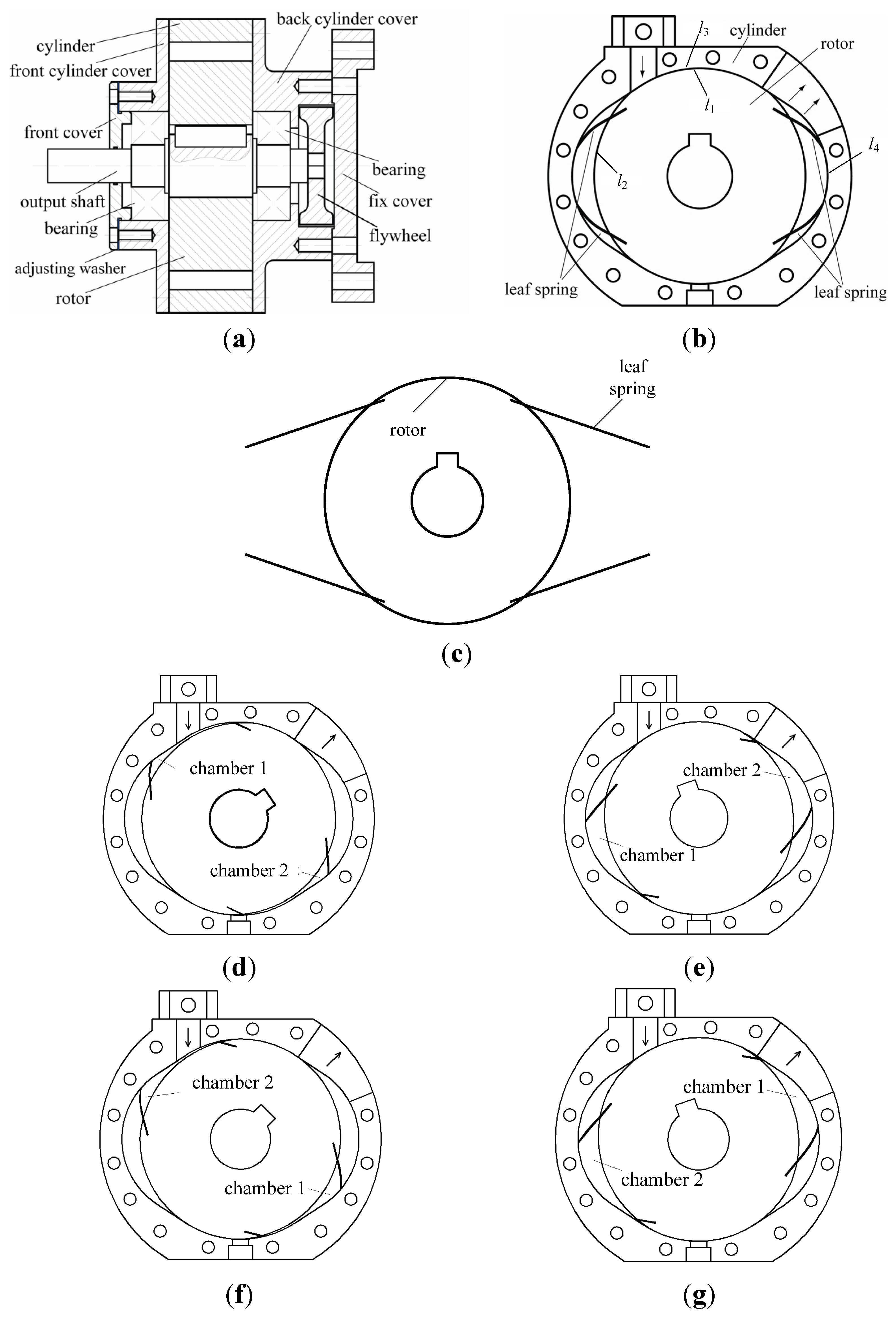
2. Structure and Principle, Application Mode

The leaf spring rotary engine is similar to the Wankel rotary engine, which is a 4-stroke cycle engine in structure and working principle. The energy released by the air-fuel mixture drives the rotor and output shaft to move. The rotor centerline aligns with the housing centerline, which is different from the Wankel rotary engines mentioned above. The end of the spring is fixed to the rotor, and the other end depends on its elasticity to contact with combustion wall. The chemical energy is converted to mechanical energy through compression, combustion, and exhaust processes. Compared with a traditional piston engine, the leaf spring rotary engine does not require a crank and complex connecting rod mechanism. The engine operates smoothly and impact force is small when leaf springs are added to the chamber. Compared with the traditional Wankel engine, the leaf spring rotary engine removes eccentric parts so that the effect of noise and vibration due to unbalance can be eliminated. Taking flexible leaf spring gives the chamber a better sealing property than the Wankel engine. Apex seal is guaranteed by close fitting between the cylinder and the spring because of its flexibility. Leakage mainly occurs at the area between the piston and the housing. The simpler structure of the leaf spring rotary engine leads to less mass leakage than the Wankel engine between the rotor and the cylinder. Furthermore, an appropriate compression ratio is selected, which also decreases the mass of the leaf spring rotary engine [38]. The leaf spring rotary engine consists of front cylinder cover, back cylinder cover, rotor, leaf spring, cylinder, output shaft, flywheel, and so on (Figure 1a).
Figure 1. (a) Sketch of leaf spring rotary engine; (b) sketch of the rotor–spring–cylinder assembly; (c) sketch of the rotor; (d) intake procession of the engine; (e) compression procession of the engine; (f) combustion procession of the engine; and (g) exhaust procession of the engine.
Energies 08 08086 g001
The combustion chamber is enclosed by the rotor, front and rear springs, and front and back cylinder covers. One end of the leaf spring is fixed on the rotor groove, and the other end contacts the cylinder, relying on its elasticity (Figure 1b). The leaf spring is deformed by the force between cylinder and leaf spring to change the volume of combustion chamber, which is the impetus of intake stroke, compression stroke, combustion stroke, and exhaust stroke.
The working process of the leaf spring rotary engine is shown in Figure 1d–g. The designed rotary engine contains symmetric double combustion chambers. In this work, taking chamber 1 as an example to describe working process: (1) In the intake phase, releasing the stored energy from spring and gas expansion power in chamber 2 together drives the rotor to rotate. The volume of combustion chamber 1 increases, then negative pressure is formed, thus fresh air flows into combustion chamber 1 because of the pressure difference between the inside and outside. (2) In the compression phase, under the action of fly wheel inertia, the fresh charge within combustion chamber 1 is compressed and waste gas is exhausted. Flywheel inertia converts into compression energy. (3) In the combustion phase, the electric heater plug ignites the mixture, causing gas expansion and the release of stored energy together to promote the reed rotor and to inhale gas to chamber 2. (4) In exhaust phase, the spring in chamber 1 is compressed by inertia force to drive gas to discharge.
Based on the structure of the leaf spring rotary engine, the rotor is enclosed within two circles. The original point of the absolute coordinate is located at the cross-section center of the output shaft. The center of one circle, marked with l1, is placed at the original point and the radius is 25 mm, whereas the center of the other circle, marked with l2, is situated at (2.2, 0) and the radius is 26.6 mm. Taking the leaf part of the coordinate system as an example, the outline equation of the rotor is shown as Equation (1).
{ ( x 2.2 ) 2 + y 2 = 26.6 2         x 1 < x < x 2 x 2 + y 2 = 25 2                      x 2 < x < 0
The outline of the cylinder is symmetrical about the original point. Taking the segment of the cylinder in the second quadrant of the coordinate system as an example, it is surrounded by arcl1, arcl2, and the tangent line of the two arcs, l4. The center of circular arcl3 is situated at (−10, 0) and the radius is 19.5 mm. The molded line of the cylinder is shown as Equation (2).
{ ( x + 10 ) 2 + y 2 = 19.5 2      x 3 < x < x 4 a x + b y + c = 0                 x 4 < x < x 5 x 2 + y 2 = 25 2                     x 5 < x < 0
where, x3 is the cross point coordinate between l3 and abscissa axis, x4 is the cross point abscissa of l3 and l4, and x5 is the cross point abscissa between l1 and l4.
The intake port positions the upper side of the arc l1 and is adjacent to the cross point of l1 and l4. The intake port is completely closed by the rotor during compression in order to prevent combustible mixture in the non-combustion space. In addition, there is no clearance to allow the air fleeing in the cylinder because the cylinder design matches the rotor suitably.
The present state of battery technology severely limits the development of pure electric devices. Until significant advances in battery technology are made, hybrid propulsion systems provide an interim solution [39]. The leaf spring rotary engine is a potential power source to power generation due to high density, which makes it convenient for transportation. The goal of the MEMS Rotary Engine Power System (REPS) project is to develop an autonomous, portable power system capable of producing electrical power on the order of watts with an energy density better than conventional batteries [40]. Such system leverages the specific energy advantage of liquid hydrocarbon fuels over current portable power sources. The MEMS REPS is an interdisciplinary project divided in research areas such as engine fabrication, engine sealing, fuel delivery, packaging and testing. The MEMS REPS unit will be designed to produce power from the leaf spring rotary engine that will be integrated with an external small electrical generator. The leaf spring rotary engine is like a Wankel engine that operates on a 4-stroke cycle. A fuel and air mixture is drawn into the engine through the carburetor. The electrical generator extracts mechanical power from engine with a coupled shaft. In a series hybrid configuration, the devices, including portable electronics and equipment used in remote settings, derive instantaneous performance from energy storage system, but its sustained operation relies on an auxiliary power-generating unit (APU). The engine operates in a gasline-fueled spark-ignited mode. In this engine, the shaft will be used to convert chemical energy into mechanical power. A coupled shaft will be needed to extract mechanical power to drive electrical generator used to generate electrical energy. The output shaft of the rotary engine is centered relative to the rotor housing, and can be easily coupled with a generator to produce electricity. Electric energy will be stored in batteries, which can be used to provide energy for small devices like small aircrafts, satellites, robots, transport devices and so on. At the same time, devices will provide energy feedback to APU. A novel generator may need to be designed to match the leaf spring rotary engine due to its characteristics. Previously, linear generators to match free-piston engines have been designed and investigated [41]. Therefore, the leaf spring rotary engine is a very efficient and reasonable power plant for electric equipment. The leaf spring rotary engine may be a potential power source for future application in small electric devices.
When used as a range extender for a series PHEV, the rotary combustion engine showed better performance than the reciprocating engine. The rotary engine has the advantage of a high power-to-weight ratio, more compact size and packaging, and reduced noise, vibration and harshness (NVH) compared to the reciprocating engine. Reduced NVH is especially critical when extending the range of electric vehicles, as the occupants of the vehicle will be accustomed to the smooth and silent operation of electric traction system, and may dislike NVH produced by a conventional power train unit with a reciprocating engine range extender. These benefits come at the expense of lower fuel economy [42]. In a series hybrid, the internal combustion engine can be operated at its most efficient point by maintaining a specific constant speed. An electronic engine control unit (ECU) is also required to control the fueling and ignition timing on a cycle-by-cycle basis to control the engine speed and stroke.

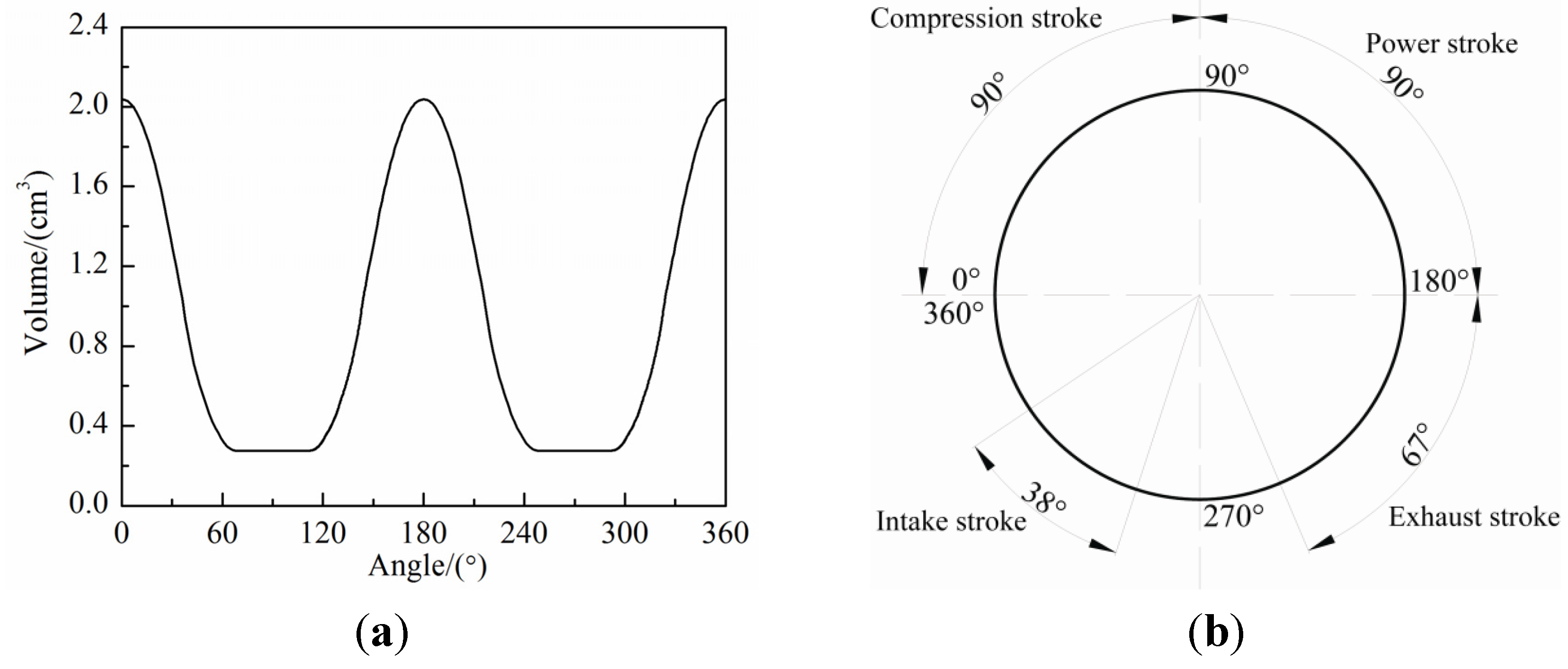
3. Volume Calculation

The flexibility of the leaf spring determines the volume variation of the leaf spring rotary engine. Thus the spring deformation calculation becomes an important part of the volume calculation. The leaf spring rotor is assembled as a cantilever structure, and remains perfectly elastic in the work process. The spring deformation, which is caused by concentrated load imposed on the free end, is regarded as static behavior without considering complex dynamics characteristic. The geometric nonlinear deforming of the leaf spring satisfies the Euler–Bernoulli Equation (Equation (3)).
y [ 1 + ( y ) 2 ] 3 2 = M E I
It yields Equations (4) and (5).
y ( x ) = 0 x W (λ) 1 [ W (λ) ] 2 d λ
W ( x ) = p 2 E I [ x 2 ( L l ) 2 ]
Moreover, the length of the leaf spring can be calculated using arc length integral Equation (6).
L = 0 L 0 [ 1 + ( y ) 1 2 ] d x
W(x) is the function of horizontal displacement l of the free end. Using trial and error method [43,44], Matlab calculation procedures is performed to calculate the horizontal displacement l in each load step applied to the free end of the leaf spring. The flowchart of the Matlab program is illuminated in Figure 2a [45]. The deflection curve of the leaf spring can be obtained by fitting a constant length to the leaf spring, and then getting the volume of combustion chamber by mathematical integration.
Variation of combustion chamber volume corresponds to rotary angle during the engine work process. The relationship of them is shown in Figure 2a. This finds a compression ratio of about 7.3 and the working volume of the combustion chamber is 1.77 cm3.
With regard to the change rule of the combustion chamber volume, and based on the locating standard point, which is the midpoint of the rotor molded line facing the combustion chamber, the phase chart of the leaf spring rotary engine is shown in Figure 2b.
Figure 2. (a) Variation profile of combustion chamber volume; (b) The phase chart of the leaf spring rotary engine.
Energies 08 08086 g002

4. Methods

4.1. Numerical Methods

The mixture in the chamber was simulated using a commercially available CFD code, FLUENT 14.5. The time-dependent ordinary sets of the continuity equation, the three-dimensional Navier–Stokes (N-S) equation, the energy conservation equation and the species conservation equations were solved with the finite volume method. The code allows for multi-component diffusion, thermal diffusion, variable thermochemical properties and variable transport properties. A realizable κ ε turbulence model and finite-rate/eddy-dissipation model are used to account for the effect of factors on the combustion characteristics. Turbulence energy κ and ε are introduced to N-S equation by Re-Normalisation Group (RNG) κ ε method. Then, new turbulence model can be written as follows:
( ρ k ) t + ( ρ k u i ) x i = x j ( α k μ e f f k x j ) + G k + ρε
(ρε) t + (ρε u i ) x i = x j ( α ε μ e f f ε x j ) + C 1 ε ε k G k C 2 s ρ ε 2 k
where μ e f f = μ + μ t , μ i = ρ C μ k 2 / ε , C 1 ε = C 1 s η( 1 η / η 0 ) / ( 1 + β η 3 ) , η = ( 2 E i j E i j ) 1 / 2 k / ε , E i j = 1 2 ( u i x j + u j x j ) , C μ = 0.0845 , α k = α s = 1.39 , C 1 s = 1.42 , C 2 s = 1.68 , η 0 = 4.337 , β = 0.012 .
The turbulent model can apply to computer compressible fluid, which needs to reflect the change of density. Adding new source term to κ equation and ε equation can be written as follows:
S k = 2 3 ρ k u ¯ 2 3 μ l [ u ¯ ] 2
S ε = [ 2 3 C 1 C 2 ] ρε u ¯ 1 3 C 1 ρ [ u ¯ ] 2
Centrifugal forces of rotary engine affect fluid dynamics. When centrifugal acceleration is parallel to the solid wall of the increasing boundary layer, secondary flow happens in field parallel to the boundary layer. When centrifugal acceleration is perpendicular to the solid wall, the structure of turbulence is affected; meanwhile, eddy-dissipation rate increases and turbulence energy reduces. Therefore, based on modified method of Buoyancy flow, eddy-dissipation rate can be modified as follows [46,47,48]:
S ε = ε k [ C 1 G k ( 1 + C 3 R f ) C 2 ρε ]
where R f = 0.5 ρ v ( r w ) 2 / G k , G k = 2 μ l S i j S i j ¯ , μ l = ρ C μ k 2 / ε , C μ = 0.0845 , C 1 = 1.44 , C 2 = 1.92 , C 3 = 1 .

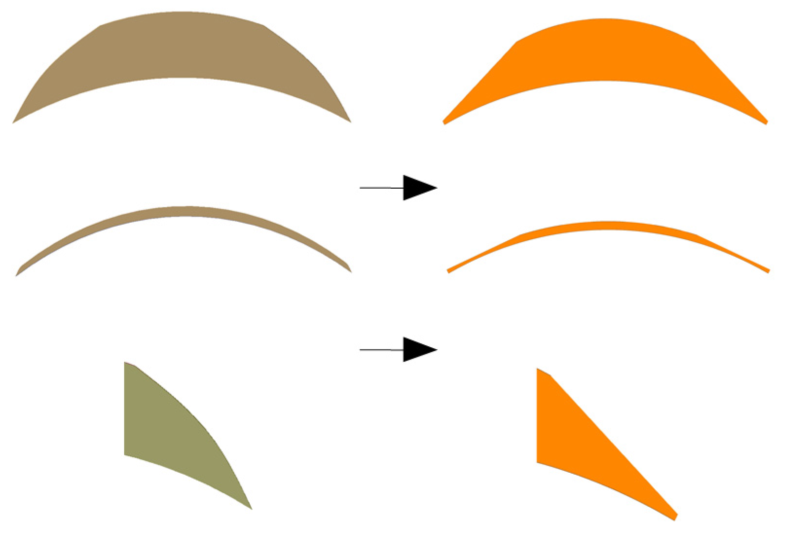
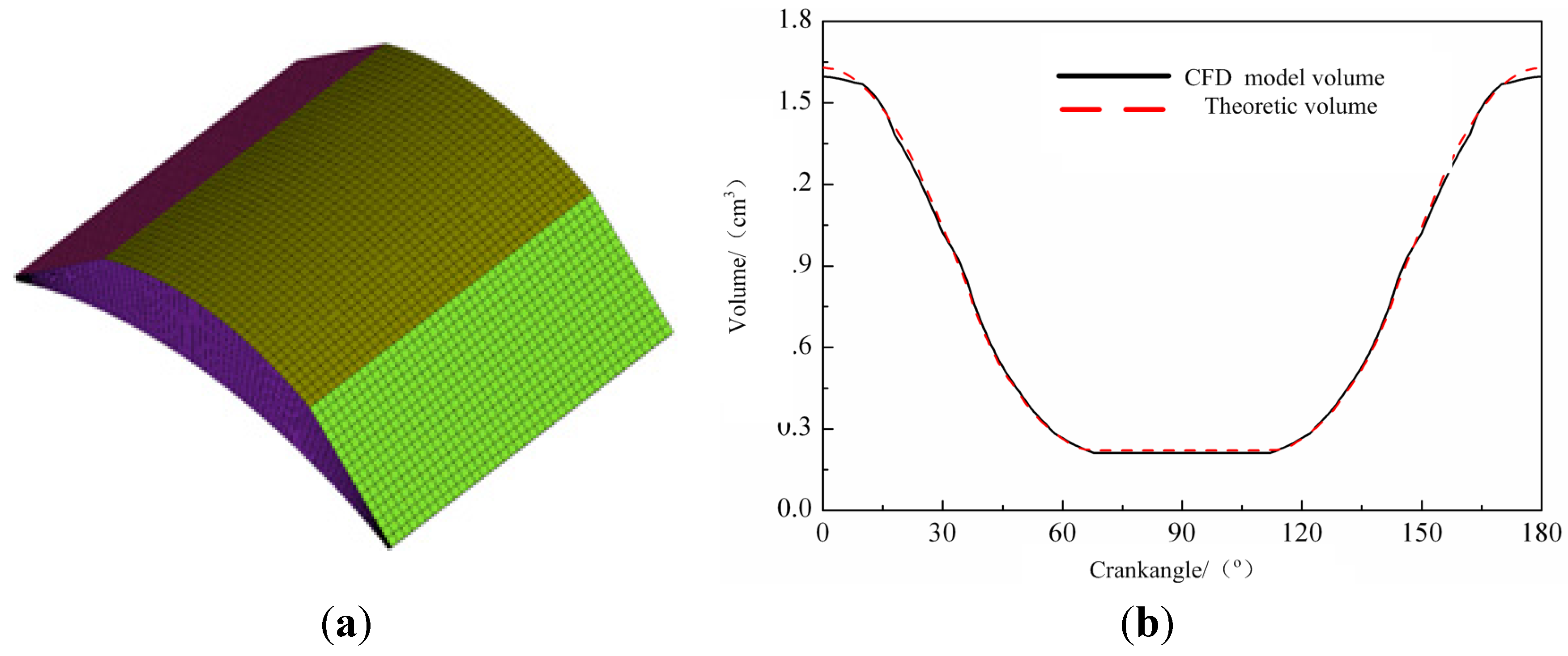
4.2. Equivalent Modeling Method

It is known from engine principles that the combustion model of chamber space excites three dynamic boundaries. In this paper, the rotor was set as a fixed reference system. The cylinder revolves around the center point of the rotor, and the leaf spring is compressed or extended by force. This method can save on simulation calculation costs. A sharp corner excites between leaf spring and rotor under ideal condition due to a narrow chamber. A sharp corner is not helpful for CFD mesh generation and combustion computation. The contact area for the spring and cylinder is not constant and deflection value near the fixed end is less than one the value near the free end. Thus it is able to consider the leaf as two parts. The one part is incorporated into the cylinder, and the other part is considered the linear segment. The two lines represent reeds; the upper line is cylinder profile, while the lower line is the thermal profile of the rotor, as shown in Figure 3. Length of the epitrochoidal increase or decrease depends on change of chamber volume. The angle between spring and rotor changes from sharp to large acute angle. Therefore, ensuring the accuracy of computation and reducing the difficulty of meshing reduce the calculation costs.
Figure 3. Equivalent model of chamber.
Energies 08 08086 g003
The mesh density was finalized at 42,640 grids and 46,848 hexahedral elements (Figure 4a). Both of the springs and the cylinder profile constitute dynamic boundaries; the rotor profile constitutes a static boundary. The contrast diagram shown in Figure 4b is given for CFD simulation and theoretical calculation. It can be seen from Figure 4b that equivalent modeling method is valid and reasonable. Chamber volume using mathematical method is very accurate and credible because the structure of the chamber is relatively fixed without considering the effects of temperature on material distortion.
Figure 4. (a) Chamber mesh model; (b) Contrast diagram for CFD simulation and theoretical calculation.
Energies 08 08086 g004

5. Analysis of Combustion Process

5.1. Initial Conditions and Boundary Conditions

In present work, intake parameters were imposed on the entire computational domain as initial conditions (shown in Table 1) for numerical simulation. In order to take into account combustion characteristics, the effect of heat transfer between the outer wall and air is not considered. Thus, wall boundary is in adiabatic condition. Parts temperatures are estimated by the iteration method, which is applied on the boundary of fluid–solid coupling [49]. Crankangle is at 90°, corresponding to the ignition start.
Table 1. Initial conditions and boundary conditions.
ParameterValueUnit
Combustion Duration3.2ms
Inlet pressure0.101325MPa
Inlet Temperature300K
Excess air ratio1
Cylinder Wall Temperature380K
Cover Surface Temperature360K
Rotor Surface Temperature450K
Spring Surface Temperature400K
Ignition Time90°
Fuel LHV44200KJ/Kg

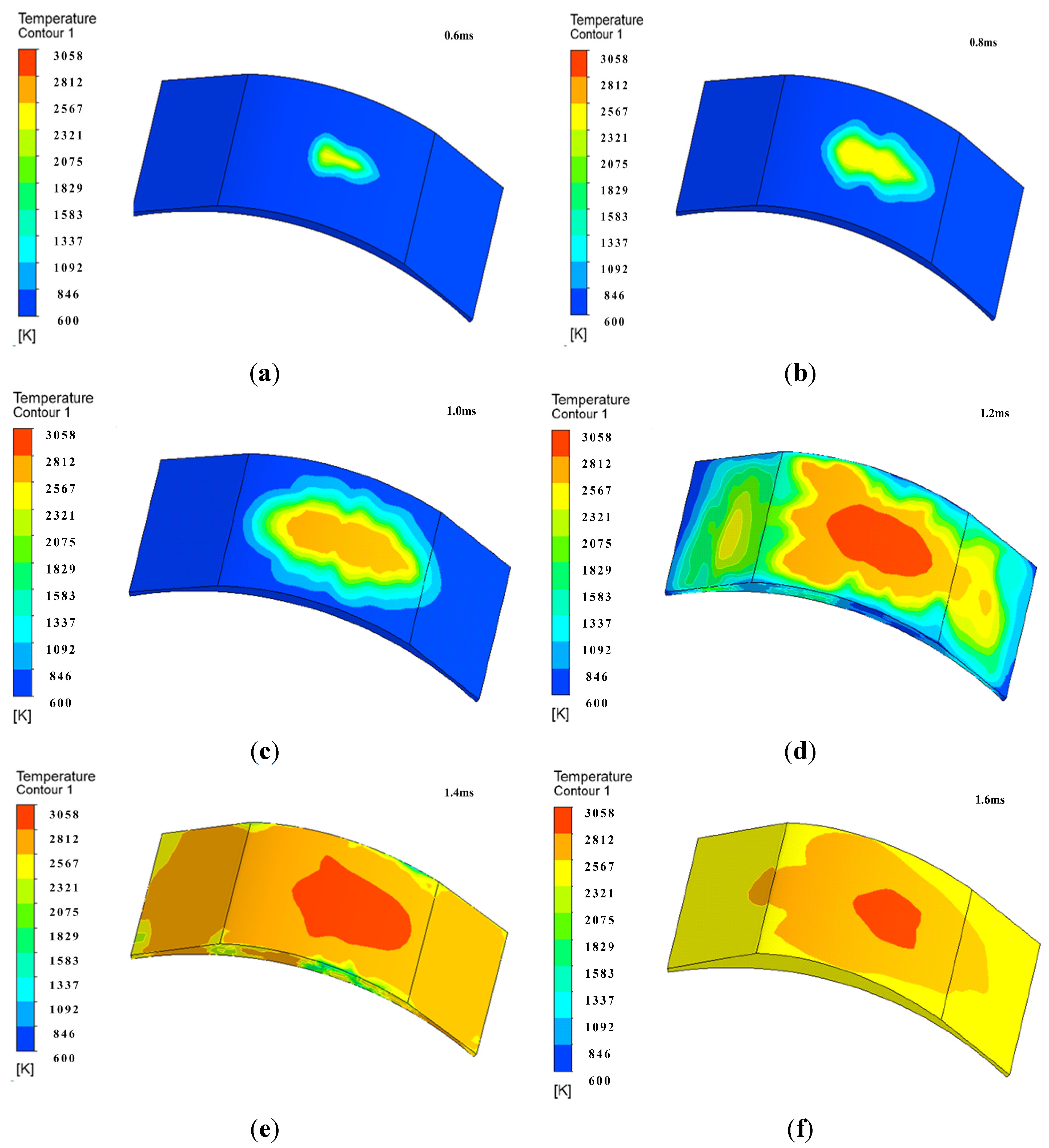
5.2. Numerical Simulation of Combustion Process

Numerical simulation of combustion process is helpful to further master combustion mechanism. Temperature is one of the most important parameters to characterize a combustion process. Therefore, choosing the temperature field (shown in Figure 5) represents the combustion process of the engine.
At the primary stage, constant-volume combustion happens. Additionally, flame kernel spins with engine rotation. When counter-clockwise is set as a reference system, unburned mixture ahead of the flame flows in the same direction of the flame and unburned mixture behind the flame diffuses in another direction. In others words, there are more mixtures into flame front at the same moment. It is found that flame backwards mixture propagation speed is higher than anterior mixture at 0.8 ms. Propagation speed of flame with calabash shape was much smaller than rotational speed (shown in Figure 5b). Before 1 ms, flame in the region between the rotor and fire surface cannot propagate to the reed. Thus, heat load on the spring is relatively small. After 1 ms, flame propagation speed started to increase and temperature of mixture closed to pre- and post-springs keeps rising. Elastic energy of the front reed was released, which led to volume increasing close to the front reed. Therefore, flame propagation speed started to increase at anticlockwise direction under the action of pressure difference and a new flame kernel was formed at the center of the front reed (shown in Figure 5d). After that, combustible mixture was full combustion so that chamber temperature continuously increased up to 3058 K (Figure 5e,f). The region of maximum temperature concentrated in the middle of the cylinder and the rotor.
Figure 5. (a) Temperature field at 0.6 ms; (b) Temperature field at 0.8 ms; (c) Temperature field at 1.0 ms; (d) Temperature field at 1.2 ms; (e) Temperature field at 1.4 ms; (f) Temperature field at 1.6 ms.
Energies 08 08086 g005

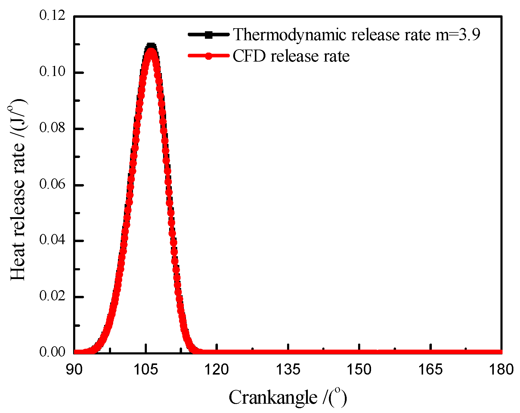
5.3. Verification of Heat Release Rate

Based on CFD simulation of engine combustion, thermodynamic release model was able to verify by CFD simulation results. Therefore, the results of thermodynamic simulation were feasible and reliable. Heat release model adopted the wiebe release model [50] in this paper. Thermodynamic analysis had been made in a previous paper [51]. In order to better contrast, the same initial conditions were employed in adiabatic CFD model and thermodynamic release model. That is, engine speed was 3000 r/min, compression beginning pressure was 0.1013 MPa, initial temperature was 305 K, excess air coefficient was 1, wall was adiabatic, and ignition timing was 90° crankangle. Heat release model was checked by modifying weight coefficient m and empirical coefficient a. In the present work, m and a were 3.9 and 3, respectively (shown in Figure 6).
Figure 6. Verification of the thermodynamic model.
Energies 08 08086 g006

6. Results and Discussion
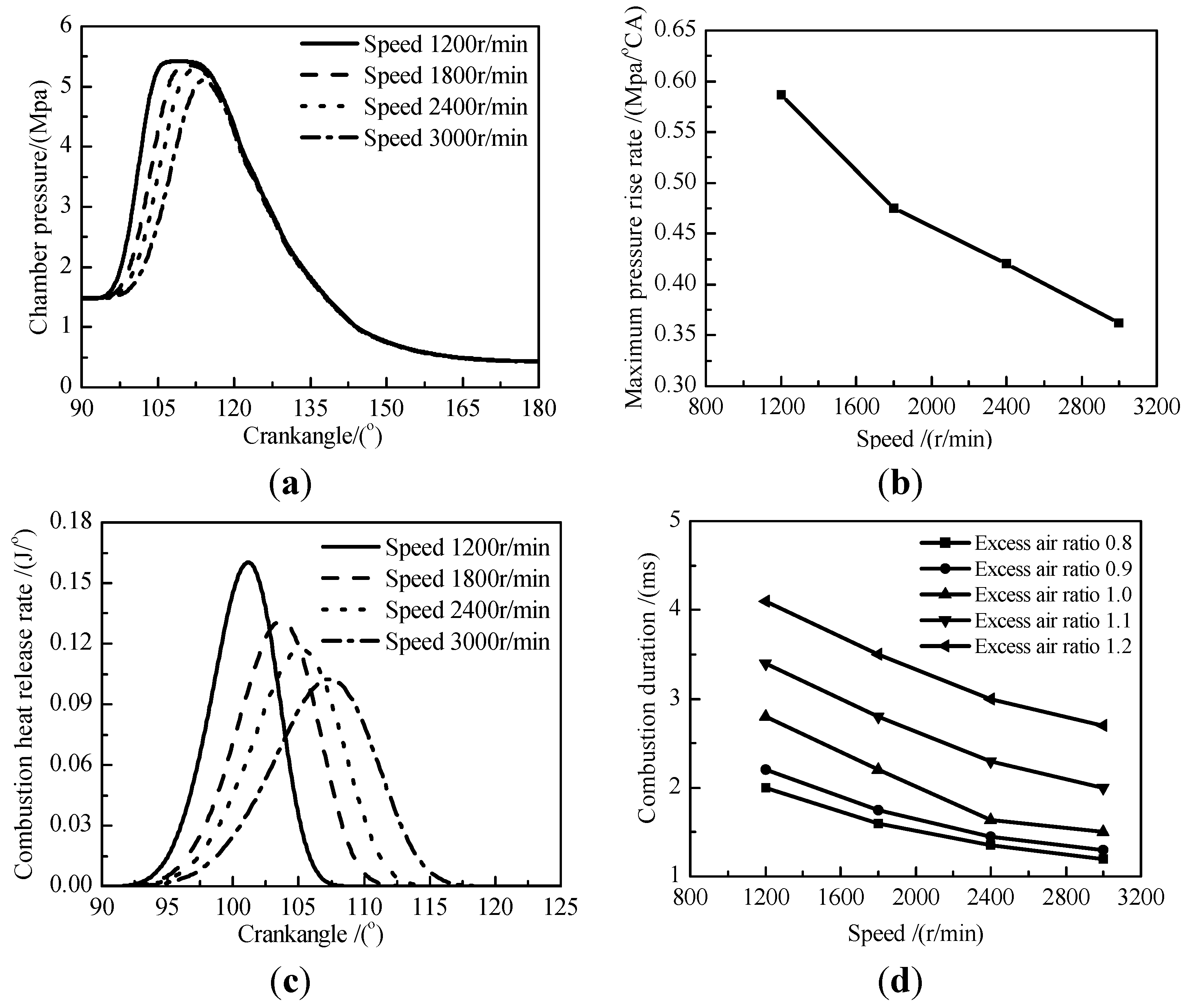
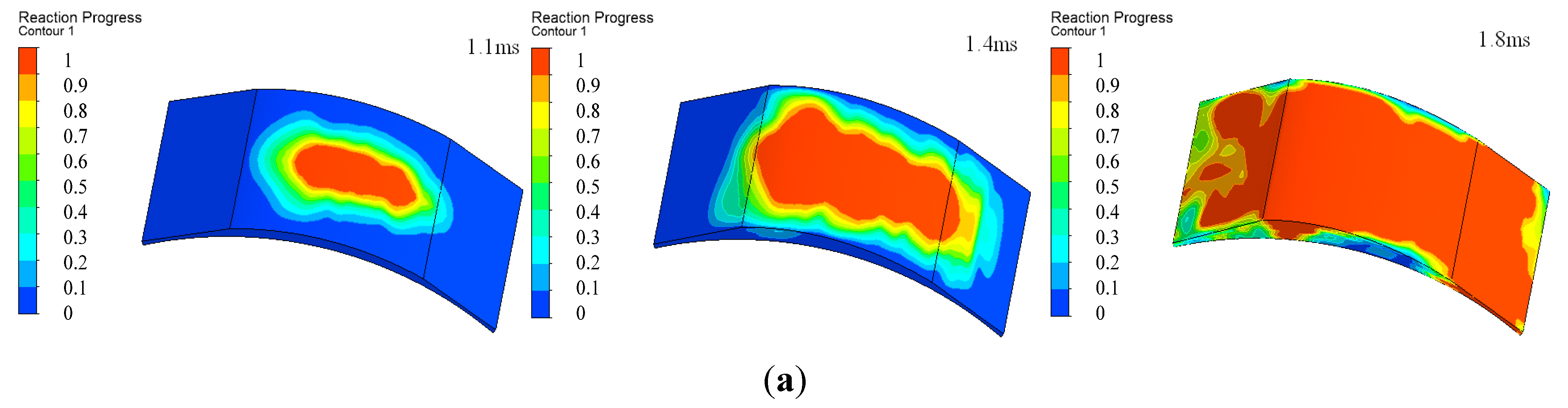
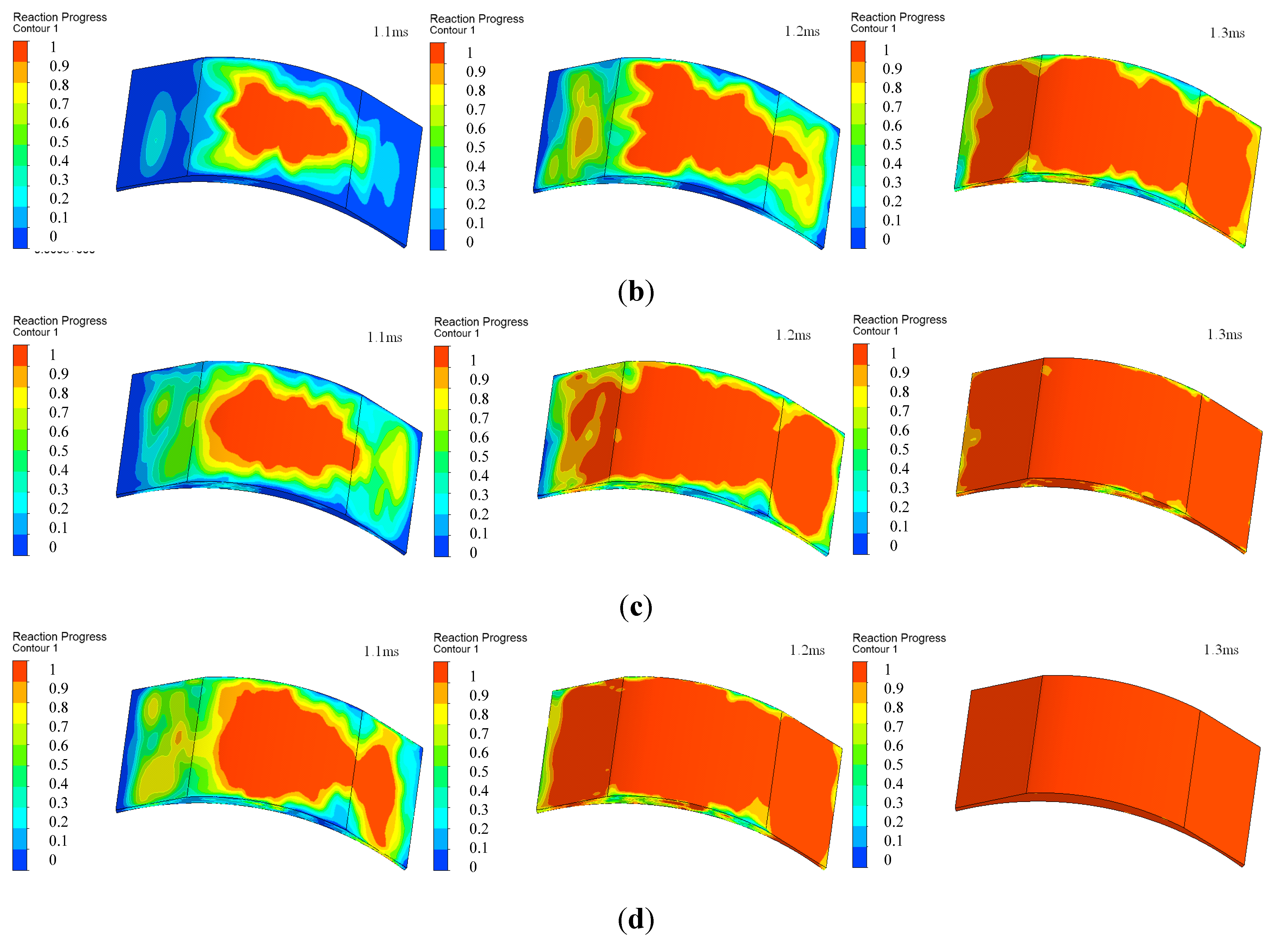
Combustion characteristic of leaf spring rotary engine can be investigated by mixture pressure, heat release rate, burning duration, maximum pressure rise rate and so on. Parameters for engine speed, excess air coefficient, initial pressure and initial temperature are important to combustion simulation. In this paper, the combustion characteristic and combustion processes at different initial conditions were investigated by CFD model. Combustion initial angle is compression end angle while simulating combustion process.

6.1. Speed

The effect of engine speed on chamber pressure, maximum pressure rise rate, heat release rate and burning duration seems to be negligible within the range it has been simulated. For air–fuel mixture, it is shown that four different speeds were simulated and the lower the speed, the higher the maximum pressure (Figure 7a). Lines connecting symbols are only for the sake of visualization. The increase of the engine speed results in pressure peak moving toward the larger crankangle. When the crankangle is higher than 120° and engine is at low rotational speed, the curve of pressure decreased to the same level due to the timing increase of constant volume combustion. In order to understand this result, maximum pressure rise rate can be examined (Figure 7b). Maximum pressure rise rate decreases with engine speed increase. The value changes from 0.47 Mpa/°CA at 1200 r/min to 0.34 Mpa/°CA at 3000 r/min, decreasing by 27.7%.
With the increase of the engine speed, the curve of heat release rate moved toward the right and covers a wider range of crankangle (Figure 7c). The peak value decreases by 65% when engine speed changes from 1200 r/min to 3000 r/min. With the same excess air ratio condition, the increase of engine speed is helpful for reducing combustion duration (Figure 7d), i.e., flame propagation speed is proportional to engine speed. The reason is that turbulent flow in chamber results in the increase of flame wrinkle due to increasing speed so that unburned mixture into flame speeds up. Furthermore, it can be seen from Figure 7d that combustion duration increases with the rising of excess air ratio for the same engine speed and the time interval becomes large.
Figure 7. (a) Chamber pressure for different speed; (b) Maximum pressure rise rate for speed. (c) Combustion heat release rate for different speed; (d) Combustion duration for different excess air ratio and speed.
Energies 08 08086 g007

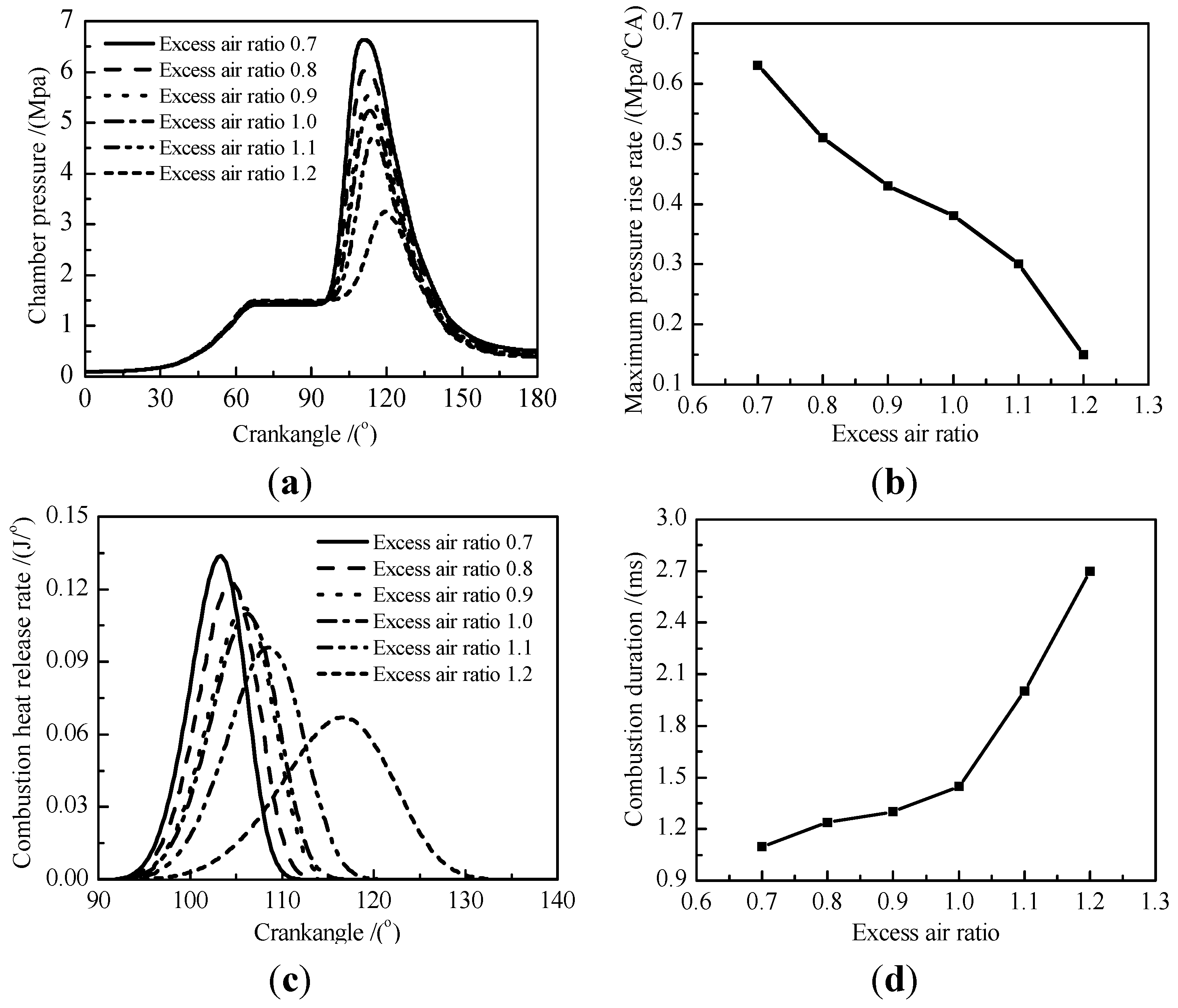
6.2. Excess Air Ratio

With the same engine speed for 3000 r/min and fully-opened throttle, peak pressure in chamber decreases with excess air coefficient increase (Figure 8a). Based on an excess air coefficient of 1, the proportion of peak pressure toward the two sides is increasing. The peak pressure at excess air ratio 1.2 is obviously lower than the one at excess air ratio 1.1. With the increase of the excess air ratio, peak pressure moves toward the right and maximum pressure rise rate decreases from 0.63 MPa/°CA to 0.15 MPa/°CA (Figure 8b). The whole curve is on the decline and the trend becomes slow near an excess air ratio 1.0. Figure 8c shows that as crankangle increases, the difference among several excess air ratios becomes larger. The excess air ratio 1.2 takes much longer distance to reach its peak heat release rate. In addition to the significant difference in terms of chemical kinetics, mass ratio also plays an important role in yielding this result. Combustion duration and excess air ratio profiles are plotted in Figure 8d. It can be seen that burning duration is gradually increasing among the range.
Figure 8. (a) Chamber pressure for excess air ratio; (b) Maximum pressure rise rate for excess air ratio; (c) Combustion heat release rate for excess air ratio; (d) Combustion duration for different excess air ratio.
Energies 08 08086 g008
Figure 9 illustrates the reaction process of the chamber for different excess air ratios. Under the conditions of same excess air ratio, flame varied from laminar to turbulence with the development of combustion. In Figure 9a, flame showed obvious laminar characteristic at 1.1 ms. However, turbulence flame happened at 1.4 ms until the end of combustion due to the changes of chamber volume and gases temperature. Decreased excess air ratio increased the variation tendency and reduced the time from laminar to turbulence. It is well established that propagation speed of flame increases with decreasing excess air ratio, but increasing degree becomes smaller and smaller. Figure 9c,d shows that the reaction process is nearly the same.
Figure 9. (a) Reaction process at excess air ratio 1.1; (b) Reaction process at excess air ratio 1.0; (c) Reaction process at excess air ratio 0.9; (d) Reaction process at excess air ratio 0.8.
Energies 08 08086 g009aEnergies 08 08086 g009b

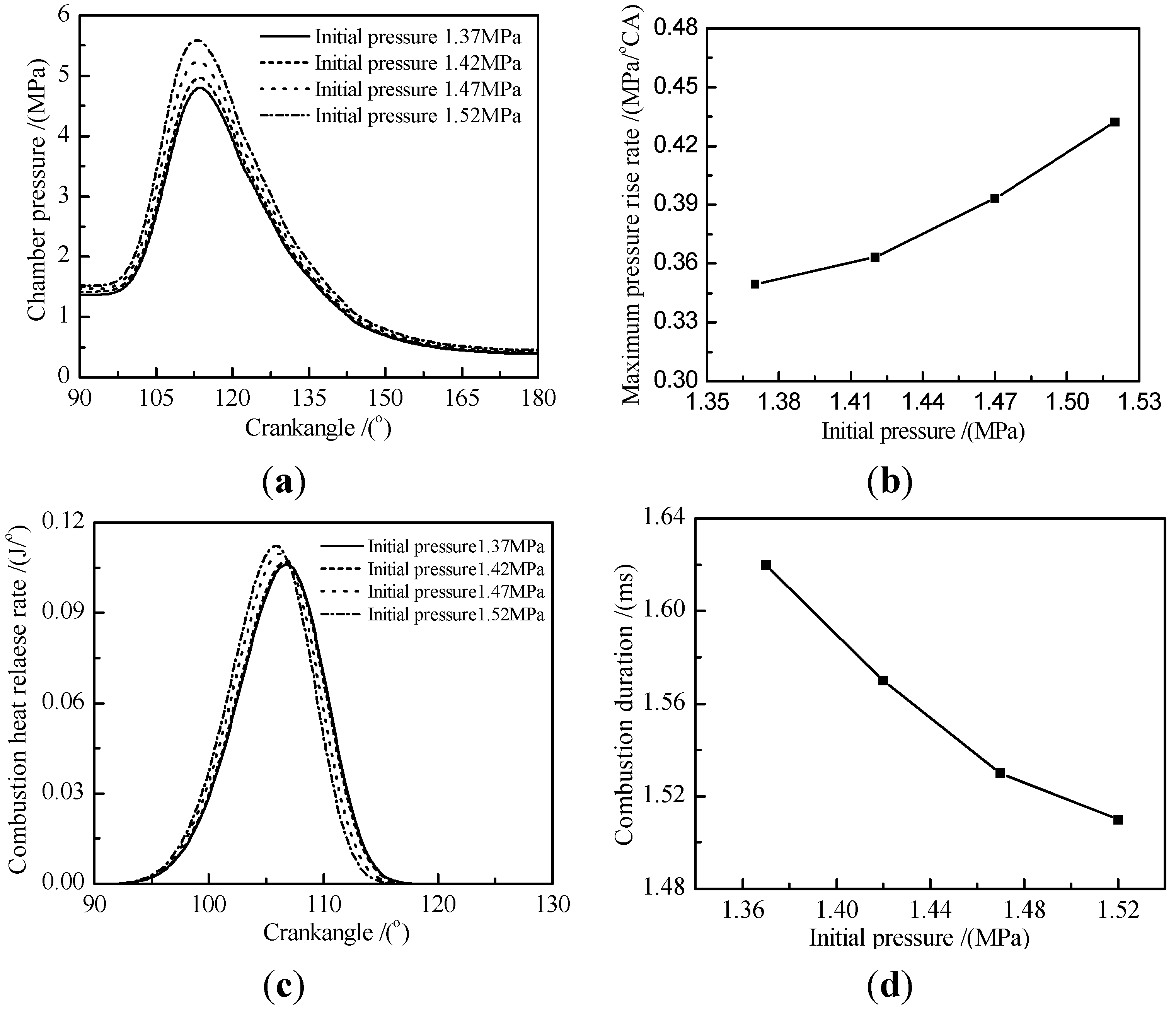
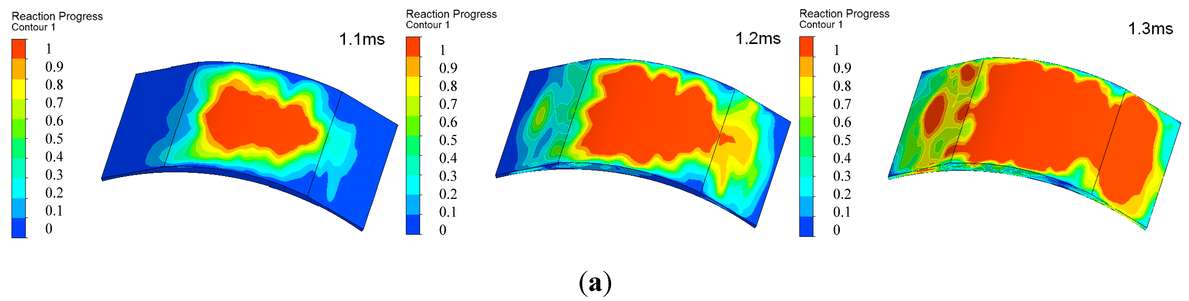
6.3. Initial Pressure

Initial pressure is another factor to affect engine combustion. No significant difference in terms of chamber pressure is found over the entire crankangle from 90° to 180° (Figure 10a). However, it can be seen that initial pressure affects the position where the pressure is up to peak. The difference increases with the increasing pressure. The pressure position is essentially an overall result of gas quality and heat transfer loss. Gas quality increase leads to the increase of initial pressure. Although heat was lost in the chamber, the effect of heat loss due to higher increase of pressure caused by gas quality can be negligible. Figure 10b shows that maximum pressure rise rate against initial pressure. It can be seen that it increases with the increasing initial pressure. The results attribute to increasing flame propagation speed caused by temperature rising. Maximum pressure rise rate increased from 0.345 Mpa/°CA to 0.435 Mpa/°CA. the difference for several initial pressures cannot be clearly identified (Figure 10c). This can be seen as the heat release rate slightly increasing as initial pressures increases and the peak shifts to the leaf. Meanwhile, combustion duration decreases from 1.62 ms to 1.51 ms and the trend slows down, as shown in Figure 10d, which indicates that flame propagation speed is enhanced.
Figure 10. (a) Chamber pressure for initial pressure; (b) Maximum pressure rise rate for initial pressure; (c) Combustion heat release rate for initial pressure; (d) Combustion duration for different initial pressure.
Energies 08 08086 g010
Figure 11 illustrates the reaction process of chamber for different initial pressures. Under the conditions of same initial pressure, combustion characteristic relies mainly on laminar with the development of subsidiary wrinkled turbulence. After 1.1 ms, turbulence gradually increased. The reason is that increased pressure leads to the increase of flame propagation speed. Another reason is variation of chamber volume. Reaction process was nearly the same, at 1.1 ms. After that, turbulence characteristic for different pressure was more obvious, and the more a combustion center started to appear. When comparing the reaction process for initial pressures of 1.47 MPa and 1.52 MPa, combustion completeness is mostly the same.
Figure 11. (a) Reaction process at pressure 1.37 MPa; (b) Reaction process at pressure 1.42 MPa; (c) Reaction process at pressure 1.47 MPa; (d) Reaction process at pressure 1.52 MPa.
Energies 08 08086 g011aEnergies 08 08086 g011b

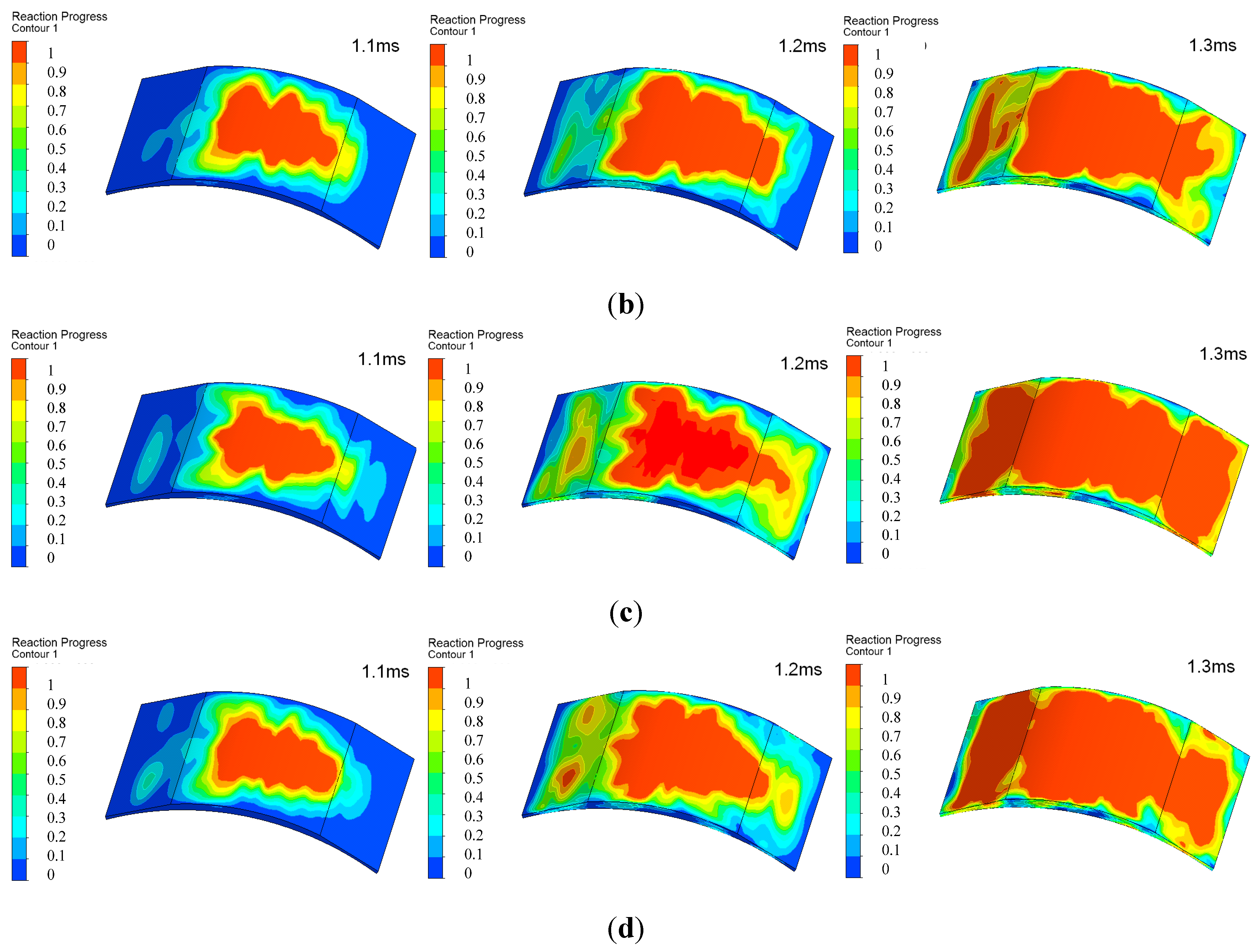
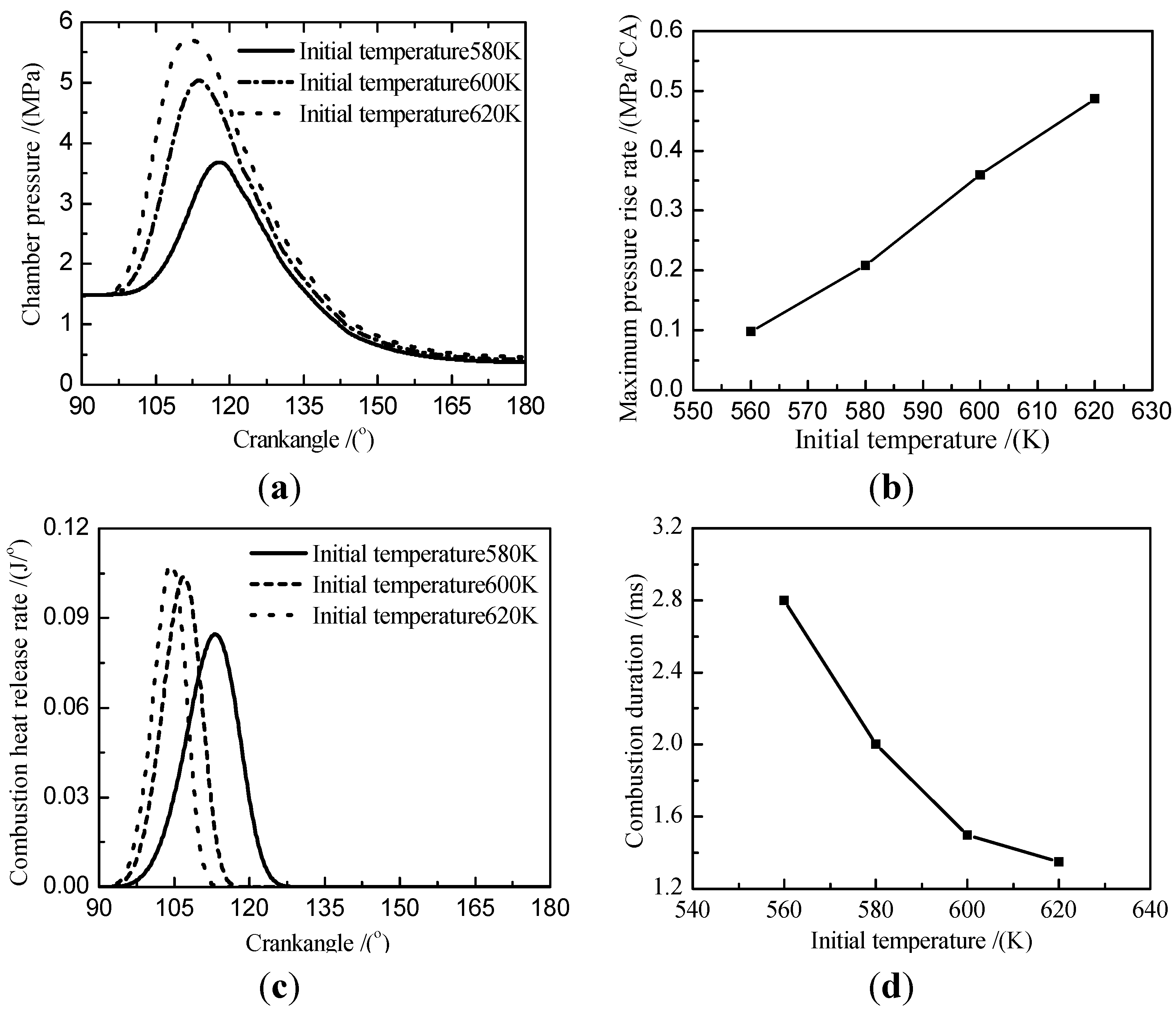
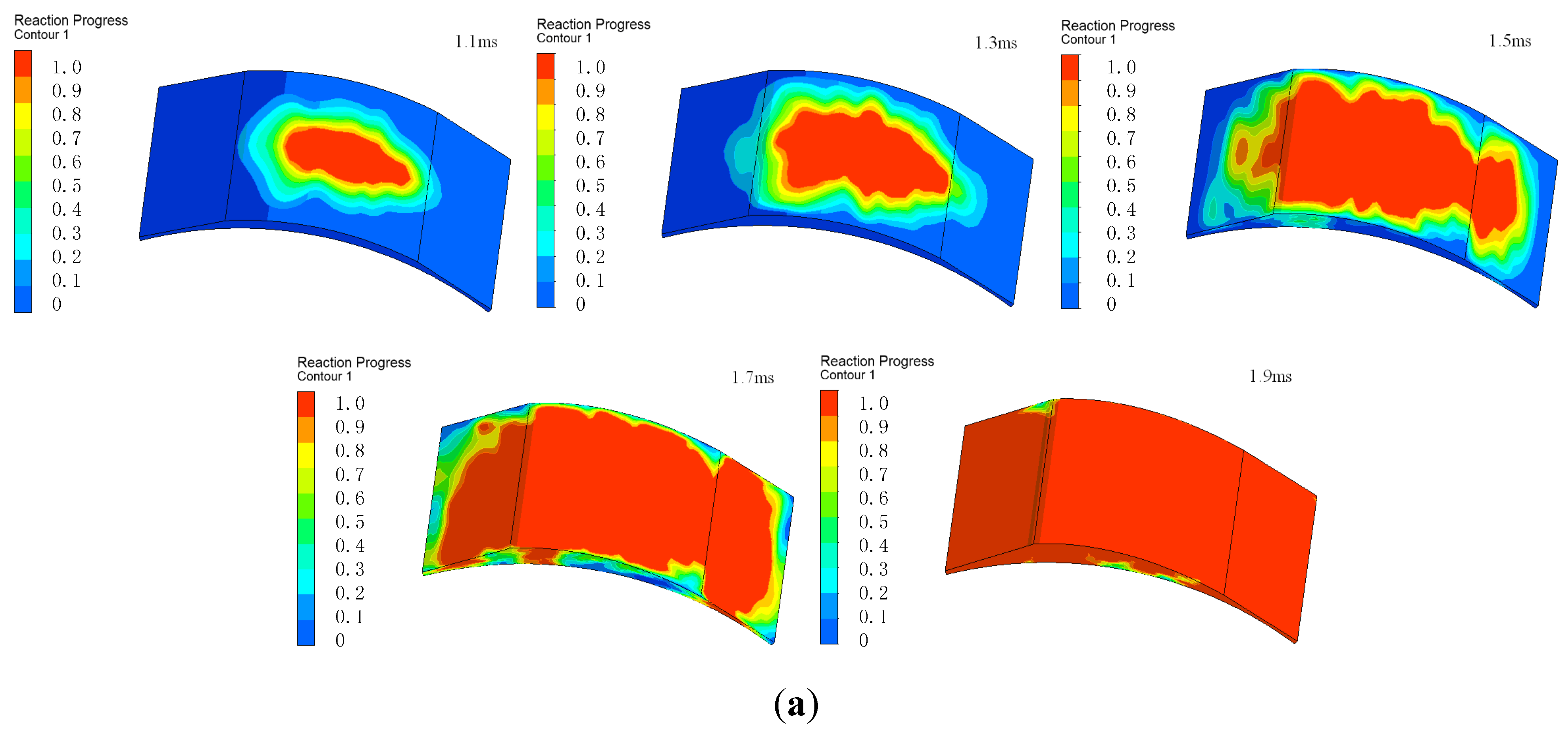
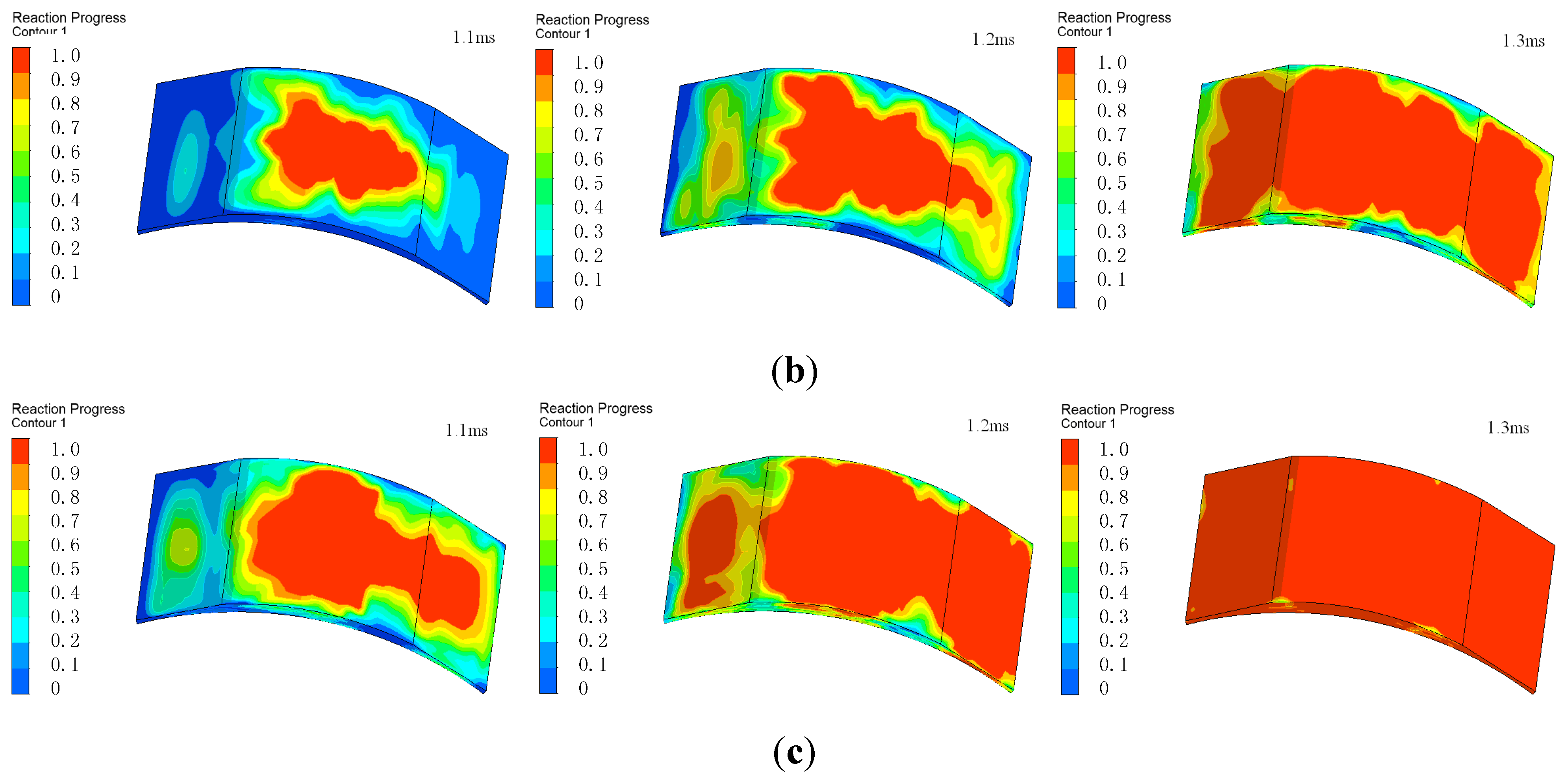
6.4. Initial Temperature

The effect of initial temperature on combustion characteristics seems to be non-negligible with the range of combustion process. Taking into account the fact that the initial density of fuel/air mixture decreases as initial temperature increases, it is clear that mixture mass is inversely proportional to initial temperature under the same conditions, including engine speed 3000 r/min, excess air ratio 1 and initial pressure 1.47 Mpa. Figure 12a,b shows that chamber pressure and pressure rise rate increase as initial temperature increases. This is due to mass of fuel/air mixture decreases as initial temperature increases without other influence factors. Figure 12c,d shows that the difference for chamber pressure and heat release rate become unclear as initial temperature increases. At the same time, the peak moves toward the left. Heat release rate increases from 0.08 J/°CA at 580 K to 0.105 J/°CA at 620 K. Figure 12d indicates that flame propagation speed increases as initial temperature increases.
Figure 13 illustrated reaction process of chamber for different initial temperature. Under the conditions of the initial temperature 580 K, combustion characteristic was laminar at 1.1 ms, after that combustion characteristic relied mainly on laminar with the development of subsidiary turbulence, turbulence continues to increase, but flame propagation speed is slower. When initial temperature was up to 600 K, combustion completeness was 0.4 ms earlier than 580 K, but was 0.1 ms longer than 620 K.
Figure 12. (a) Chamber pressure for initial temperature; (b) Maximum pressure rise rate for initial temperature; (c) Combustion heat release rate for initial temperature; (d) Combustion duration for different initial temperature.
Energies 08 08086 g012
Figure 13. (a) Reaction process at temperature 580 K; (b) Reaction process at temperature 600 K; (c) Reaction process at temperature 620 K.
Energies 08 08086 g013aEnergies 08 08086 g013b

7. Conclusions

In this work, a novel leaf spring rotary engine as a new research object was used to investigate the combustion properties inside a small-sized engine. A 3D numerical model is developed to study the influence of several operative parameters on combustion characteristics. An equivalent modeling method was presented to simulate real boundary conditions. Engine speed, excess air ratio, initial pressure and initial temperature were controlled to simulate the engine operating conditions.
(1) In the process of compression, fluid motion is mainly affected by deformation of the reed. When deforming, swirl is formed near to the spring. After constant volume burning, fluid motion mainly manifested as laminar characteristics.
(2) In the process of combustion, the increase of speed makes reduction of burning duration, sustainable heat release angle increase, peak pressure and release rate decrease; when excess air ratio decreases, burning duration reduces, the curve of heat release moves to the direction decrease of crankshaft, peak pressure and release rate increases.
(3) With the same temperature condition, when initial pressure increases, burning duration reduces but the amplitude is smaller, peak pressure and release rate increases. Under different temperature conditions, the trend of burning duration is the same as the one for different pressure conditions. However, as the heat release curve and pressure shift to near the top dead center, the pressure increases at the same time.

Author Contributions

Yan Zhang, Zhengxing Zuo and Jinxiang Liu checked and discussed the simulation results. Yan Zhang confirmed the series of simulation parameters and arranged and organized the entire simulation process. Zhengxing Zuo participated in establishing the simulation model. Jinxiang Liu revised the paper. Zhengxing Zuo and Jinxiang Liu made many useful comments and simulation suggestions. In addition, all authors reviewed the manuscript.

Conflicts of Interest

The authors declare no conflict of interest.

Nomenclature

x1
Cross point coordinate of l2 and abscissa axis
x2
Cross point abscissa of l2 and l1
x3
Cross point coordinate between l3 and abscissa axis
x4
Cross point abscissa of l3 and l4
x5
Cross point abscissa between l1 and l4
M
Flexural torque at the free end [N·m]
p
Concentrated load at the free end [N]
EI
Bending rigidity of the leaf spring
l
Horizontal displacement of the free end [m]
L
Integration length of leaf spring [m]
L0
Actual length of leaf spring [m]
y
Flexibility of leaf spring [m]
W(x)
Function of horizontal displacement l of the free end
ρ
Density [kg/m3]
ui
Velocity of i direction [m/s]
Cμ
Specific heat
k
Kinetic energy of turbulent fluctuation [J]
ε
Dissipation ratio of kinetic energy for turbulent fluctuation [%]
Gk
Kinetic energy of turbulent fluctuation for buoyant force [J]
αk, αε
Prandtl number
u ¯
Mean velocity [m/s]
μeff
Effective viscosity coefficient
Rf
Richardson number
x1
Cross point coordinate of l2 and abscissa axis

References

  1. Hamilton Walker Rotary Engine. Weekly News 1968, 7.
  2. Walker, D.F.; Hamilton, P.H. A new class of rotary piston suitable for compressors, pumps, and internal combustion engines. Proc. Inst. Mech. Eng. 1972, 186, 743–753. [Google Scholar]
  3. Quasiturbine Stirling engine, Stirling engine idea on the Quasiturbine website. Available online: https://en.wikipedia.org/wiki/Quasiturbine (accessed on 1 April 2015).
  4. Gilles, S.H.; Roxan, S.H.; Ylian, S.H. Quasiturbine: Low RPM high torque driven turbine for top efficiency power modulation. ASME Turbo Expo 2007, 3, 17–26. [Google Scholar]
  5. Heiser, W.H.; Pratt, D.T. Hypersonic Airbreathing Propulsion; American Institute of Aeronautics and Astronautics (AIAA): Reston, VA, USA, 1994. [Google Scholar]
  6. Schapiro, B.; Terlitesky, L. The RKM (RKM) rotary piston machines with the jumping momentously Axis. In Proceeding of the International Conference on Sustainable Automotive Technology 2008, Melbourne, Australia, 4–9 November 2008.
  7. Janusz, P.; Dawid, D. Numerical investigation of the wave disk micro-engine concept. Int. J. Gas Turbine Propuls. Power Syst. 2008, 2, 1–8. [Google Scholar]
  8. Fernandez-Pello, A.C. Micropower generation using combustion: Issues and approaches. Proc. Combust. Inst. 2002, 29, 883–899. [Google Scholar] [CrossRef]
  9. Sirignano, W.A.; Pham, T.K.; Dunn-Rankin, D. Miniature-scale liquid-fuel-film combustor. Proc. Combust. Inst. 2002, 29, 925–931. [Google Scholar] [CrossRef]
  10. Zamaschikov, V.V. Combustion of gases in thin-walled small diameter tubes. Combust. Explos. Shock Waves 1995, 131, 10–16. [Google Scholar]
  11. Mehra, A.; Waitz, I.A. Development of a hydrogen combustor for a microfabricated gas turbine engine. In Proceeding of the Solid-State Sensor and Actuator Workshop, Hilton Head, SC, USA, 8–11 June 1998.
  12. Mehra, A.; Zhang, X.; Ayon, A.A.; Waitz, I.A.; Schmit, M.A.; Spadaccini, C.M. A six-wafer combustion system for a silicon micro gas turbine engine. J. Microelectromech. Syst. 2000, 9, 517–527. [Google Scholar] [CrossRef]
  13. Epstein, A.H.; Senturia, S.D.; Al-Midani, O.; Anathasuresh, G.; Ayon, A.; Breuer, K.; Chen, K.-S.; Ehrich, F.E.; Esteve, L.; Frechette, G.; et al. Micro-heat engines, gas turbines and rocket engines—The MIT micro engine project. In Proceedings of the AIAA 28th Fluid Dynamics Conference, Snowmass, CO, USA, 29 June–2 July 1997.
  14. Epstein, A.H.; Senturia, S.D.; Ayon, A.; Breuer, K.; Chen, K.-S.; Ghodssi, R.; Jacobson, S.; Lang, J.; Nagle, S.; Orr, D.; et al. Power MEMS and Microengines. In Proceeding of the International Conference on Solid State Sensors and Actuators, Chicago, IL, USA, 16–19 June 1997.
  15. Fu, K.; Knobloch, A.J.; Martinez, F.C. Design and experimental results of small-scale rotary engine. In Proceeding of the ASME International Mechanical Engineering Congress and Exposition, New York, NY, USA, 11–16 November 2001.
  16. Ochoa, F.; Eastwood, C.; Ronney, P.D.; Dunn, B. Thermal transpiration based microscale propulsion and power generation devices. In Proceeding of the 7th International Microgravity Combustion Workshop, Cleveland, OH, USA, 4 June 2003.
  17. Maruta, K.; Takeda, K.; Ahn, J.; Borer, K.; Ronney, P.D.; Deutschmann, O. Extinction limits of combustion in microchannels. In Proceeding of the 29th International Syposium on Combustion, Sapporo, Japan, 21–26 July 2002.
  18. Dahn, W.J.; Ni, J.; Mijit, K.; Mayor, J.R.; Qiao, G.; Benajmin, A.; Gu, Y.; Lei, Y.; Papke, M. Micro internal combustion swing enigne (MICSE) for portable power generation system. In Proceedings of the 40th AIAA Aerospace Sciences Meeting, Reno, NV, USA, 14–17 January 2002.
  19. Aichlmayr, H.T.; Kittelson, D.B.; Zachariah, M.R. Design Consideration, Modeling, and Analysis of Micro-Homogeneous Charge Compression Ignition Combustion Free-Piston Engine. Ph.D. Thesis, The University of Minnesota, St. Paul, MN, USA, 2002. [Google Scholar]
  20. Minotti, K.; Sciubba, E. LES of a Mesocombustion chamber with a detailed chemistry model: Comparison between the Flamelet and EDC Models. Energies 2010, 3, 1943–1959. [Google Scholar] [CrossRef]
  21. Yuasa, S.; Oshimi, K.; Nose, H.; Tennichi, Y. Concept and combustion characteristics of ultra-micro combustors with premixed flame. Proc. Combust. Inst. 2004, 30, 2455–2462. [Google Scholar] [CrossRef]
  22. Lee, K.H.; Hong, Y.T.; Kim, K.B.; Kwon, O.C. Stability limits of premixed microflames at elevated temperatures for portable fuel processing devices. Int. J. Hydrog. Energy 2008, 33, 232–239. [Google Scholar] [CrossRef]
  23. Maruta, K. Micro and mesoscale combustion. Proc. Combust. Inst. 2011, 33, 125–150. [Google Scholar] [CrossRef]
  24. Wang, H.O.; Luo, K.; Lu, S.Q.; Fan, J.R. Direct numerical simulation and analysis of a hydrogen/air swirling premixed flame in a micro combustor. Int. J. Hydrog. Energy 2011, 36, 3838–3849. [Google Scholar] [CrossRef]
  25. Bedr, A.L.; Rutigliano, M.; Balat-Pichelin, M.; Cacciatore, M. Atomic oxygen recombination on quartz at high temperature: Experiments and molecular dynamics simulation. Langmuir 2006, 22, 7208–7216. [Google Scholar] [CrossRef] [PubMed]
  26. Raimondeau, S.; Norton, D.; Vlachos, D.G.; Masel, R.I. Modeling of high-temperature microburners. Proc. Combust. Inst. 2002, 29, 901–907. [Google Scholar] [CrossRef]
  27. Karagiannidis, S.; Mantzaras, J.; Jackson, G.; Boulouchos, K. Hetero-/Homogeneous combustion and stability maps in methane-fueled catalytic microreactors. Proc. Combust. Inst. 2007, 31, 3309–3317. [Google Scholar] [CrossRef]
  28. Norton, D.G.; Vlachos, D.G. A CFD study of propane/air microflameStability. Combust. Flame 2004, 138, 97–107. [Google Scholar] [CrossRef]
  29. Norton, D.G.; Vlachos, D.G. Combustion characteristics and flame stability at the microscale: A CFD study of premixed methane/air mixtures. Chem. Eng. Sci. 2003, 58, 4871–4882. [Google Scholar] [CrossRef]
  30. Hua, J.S.; Wu, M.; Kumar, K. Numerical simulation of the combustion of hydrogen-air mixture in micro-scaled chambers. Part I: Fundamental study. Chem. Eng. Sci. 2005, 60, 3497–3506. [Google Scholar] [CrossRef]
  31. Hua, J.S.; Wu, M.; Kumar, K. Numerical simulation of the combustion of hydrogen-air mixture in micro-scaled chambers Part II: CFD analysis for a micro-combustor. Chem. Eng. Sci. 2005, 60, 3497–3506. [Google Scholar] [CrossRef]
  32. Kaisare, N.S.; Vlachos, D.G. Optimal reactor dimensions for homogeneous combustion in small channels. Catal. Today 2007, 120, 96–106. [Google Scholar] [CrossRef]
  33. Li, J.; Chou, S.K.; Li, Z.W.; Yang, W.M. A comparative study of H2-air premixed flame in micro combustors with different physical and boundary conditions. Combust. Theory Model. 2008, 12, 325–347. [Google Scholar] [CrossRef]
  34. Li, J.; Chou, S.K.; Yang, W.M.; Li, Z.W. A numerical study on premixed micro combustion of CH4-air mixture: Effect of combustor size, geometry and boundary conditions on flame temperature. Chem. Eng. J. 2009, 150, 213–222. [Google Scholar] [CrossRef]
  35. Lee, K.H.; Kwon, O.C. A numerical study on structure of premixed methane-air microflames for micropower generation. Chem. Eng. Sci. 2007, 62, 3710–3719. [Google Scholar] [CrossRef]
  36. Shih, H.Y.; Liu, C.R. A computational study on the combustion of hydrogen/methane blended fuels for a micro gas turbines. Int. J. Hydrog. Energy 2014, 39, 15103–15115. [Google Scholar] [CrossRef]
  37. Wan, J.L.; Yang, W.; Fan, A.; Liu, Y.; Yao, H.; Liu, W.; Du, Y.Q.; Zhao, D.Q. A numerical investigation on combustion characteristics of H2/air mixture in a micro-combustor with wall cavities. Int. J. Hydrog. Energy 2014, 39, 8138–8146. [Google Scholar] [CrossRef]
  38. Sprague, S.B.; Walther, D.C.; Park, S.W.; Pisano, A.; Fernandez, A. Effect of leakage on optimal compression ratio for small-scale rotary engine. In Proceedings of the 45th AIAA, Reno, NV, USA, 8–11 January 2007.
  39. Cawthorne, W.R.; Famouri, P.; Chen, J.D.; Clark, N.N.; McDaniel, T.I.; Atkinson, R.J.; Nandkumar, S.; Atkinson, C.M.; Petreanu, S. Development of a linear alternator-engine for hybrid electric vehicle applications. IEEE Trans. Veh. Technol. 1999, 48, 1797–1802. [Google Scholar] [CrossRef]
  40. Fu, K.; Knobloch, A.J.; Martinez, F.C.; Walther, D.C.; Fernandz-Pello, C.; Pisano, A.P.; Liepmann, D. Design and fabrication of a silicon-based MEMS Rotary Engine. In Proceeding of the 2001 ASME International Mechanical Engineering Congress and Exposition, New York, NY, USA, 11–16 November 2001.
  41. Feng, H.H.; Song, Y.; Zuo, Z.Z.; Shang, J.; Wang, Y.D.; Anthony, P.R. Stable operation and electricity generating characteristic of a single-cylinder free piston engine linear generator: simulation and experiments. Energies 2015, 8, 765–785. [Google Scholar] [CrossRef]
  42. Scott, V.; Adam, S.; Jesse, R.; Jae, W.P. A numerical investigation on the efficiency of range extending systems using advanced vehicle simulator. J. Power Sources 2011, 196, 3360–3370. [Google Scholar]
  43. Liu, J.Y.; Yuan, R. Rigid-flexible coupling dynamics with consideration of geometric nonlinearity and thermal effect. Chin. J. Solid Mech. 2008, 29, 72–76. [Google Scholar] [CrossRef]
  44. Wu, H.H.; Liu, H.; Yang, Z.Y.; Liu, P. Application of imitate linearity equal system in nonlinear problem of geometric large deformation. J. Wuhan Univ. Technol. 2008, 32, 963–966. [Google Scholar]
  45. Wang, D.J.; Zuo, Z.X. Design and numerical simulation of leaf spring rotary engine. In Proceedings of the 2012 Asia-Pacific Power and Energy Engineering Conference, Shanghai, China, 27–29 March 2012; pp. 46–50.
  46. Bradshaw, P. Effects of Streamline Curvature on Turbulent Flow; Advisory Group for Aerospace Research and Development: Neuilly sur Seine, France, 1973; pp. 169–173. [Google Scholar]
  47. Moore, J. Effects of Coriolis Forces on Turbulent Flow in Ro-tating Channels; Gas Turbine Laboratory: Cambridge, MA, USA, 1967; pp. 89–90. [Google Scholar]
  48. Sloan, D.G. Modeling swirl in turbulent flow. Energy Combust. Sci. 1986, 11, 163–260. [Google Scholar] [CrossRef]
  49. Li, Y. Simulation and Application of Solid-liquid Coupled Heat Transfer Internal Combustion Engines. Ph.D. Thesis, Zhejiang University, Hangzhou, China, 2006. [Google Scholar]
  50. Shah, R.K. Advances in heat exchanger design. Am. Soc. Mech. Eng. 1986, 66, 112–122. [Google Scholar]
  51. Zhang, Y.; Zuo, Z.X.; Yuan, C.H.; Wang, D.J. Analysis on performance of leaf spring rotary engine. Energy Proced. 2014, 61, 984–989. [Google Scholar] [CrossRef]

