
Characteristic Analysis and Control of a Hybrid Excitation Linear Eddy Current Brake

Abstract
:1. Introduction
2. Structure and Working Principle of the Hybrid Excitation Linear Eddy Current Brake
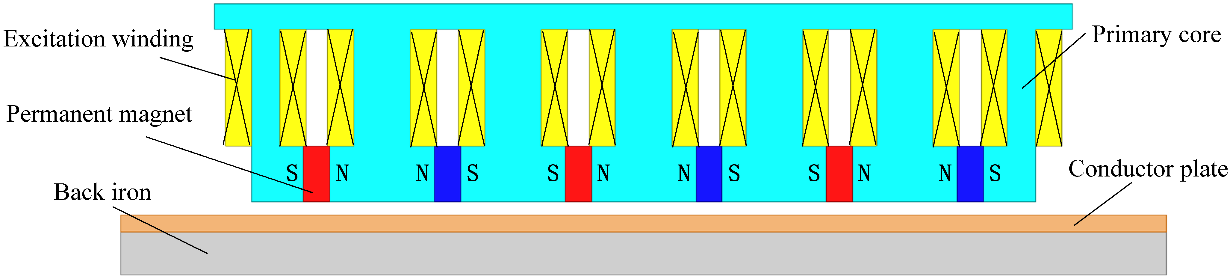
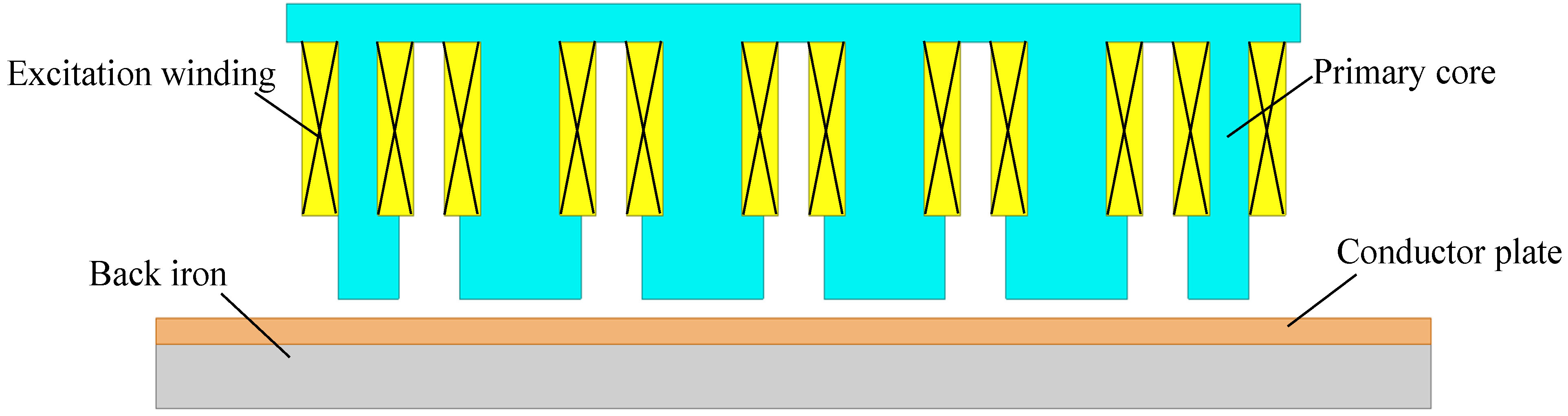
2.1. Structure of the Hybrid Excitation Linear Eddy Current Brake

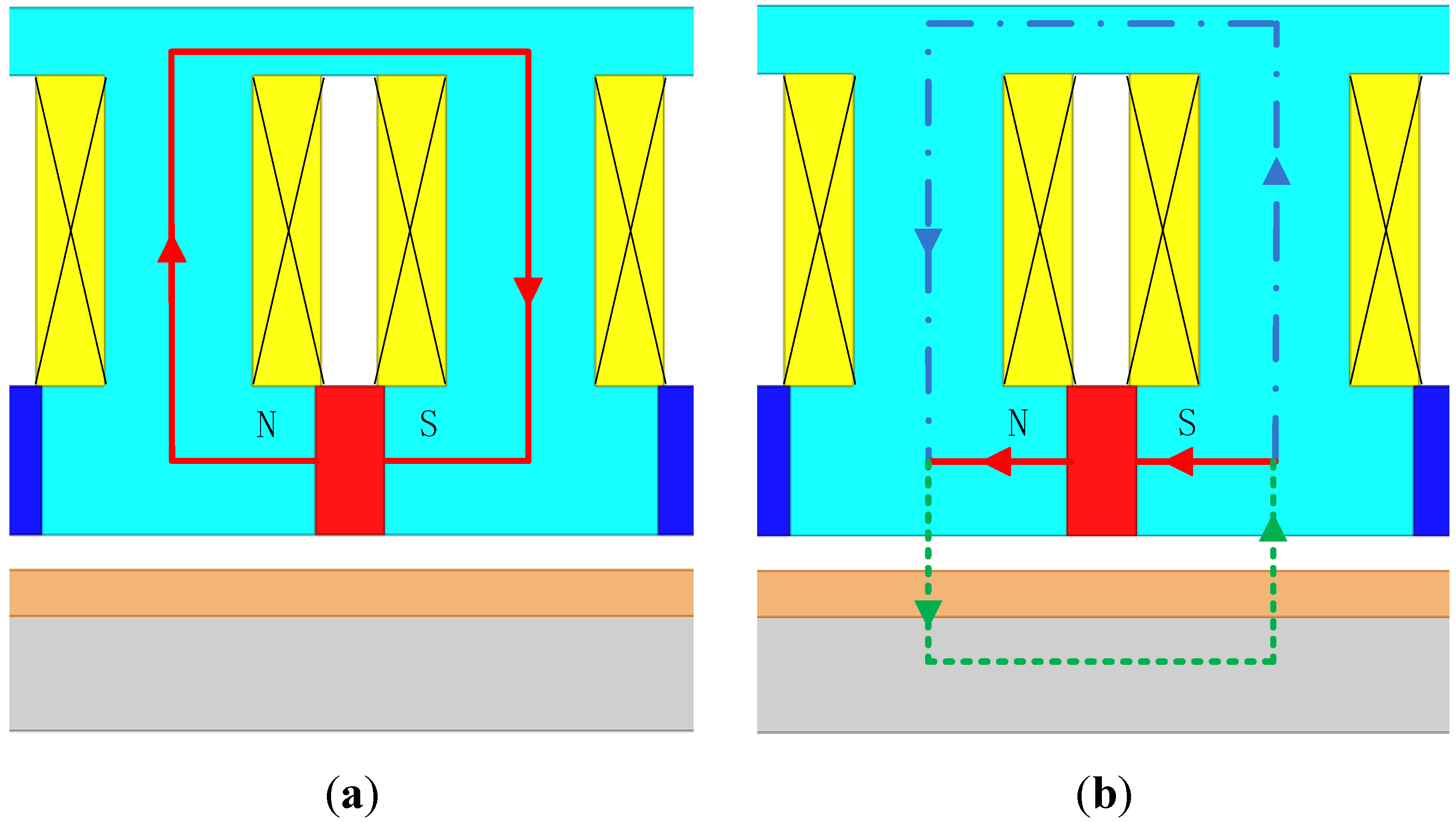
2.2. Working Principle of the Hybrid Excitation Linear Eddy Current Brake

3. Analytical Model
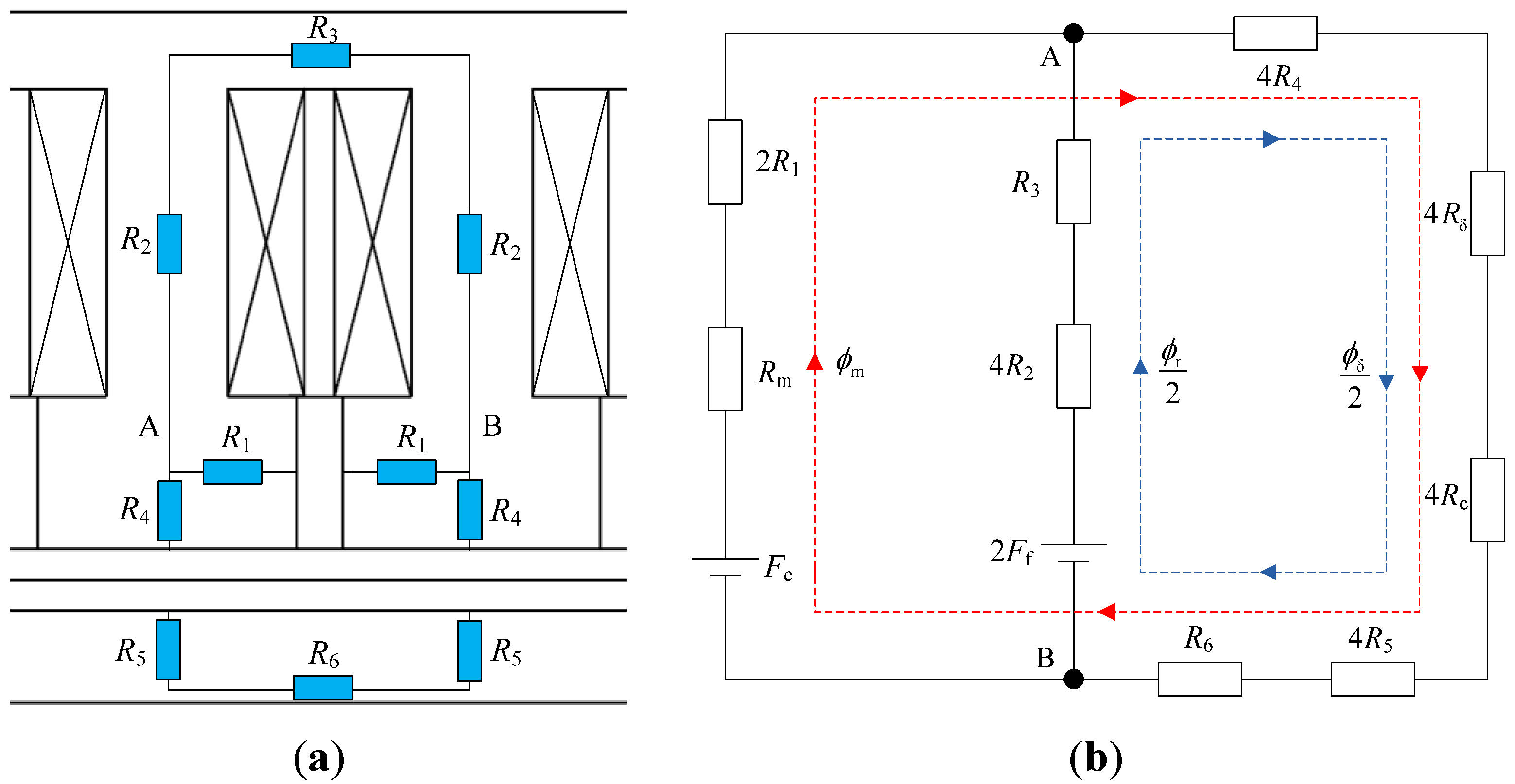
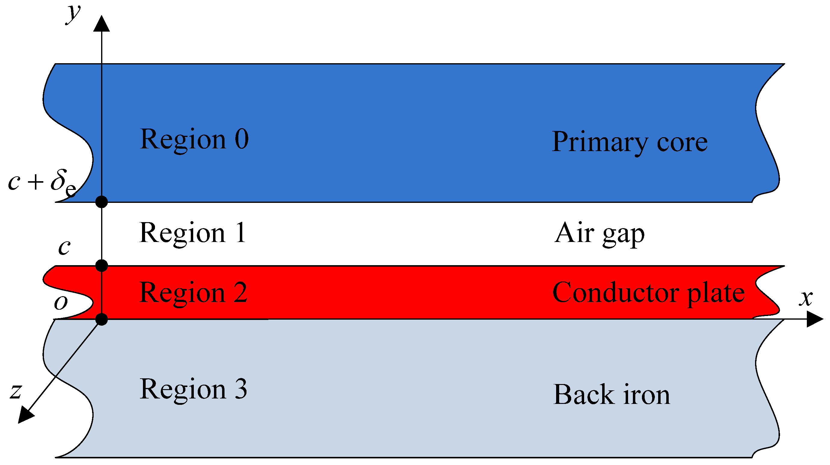
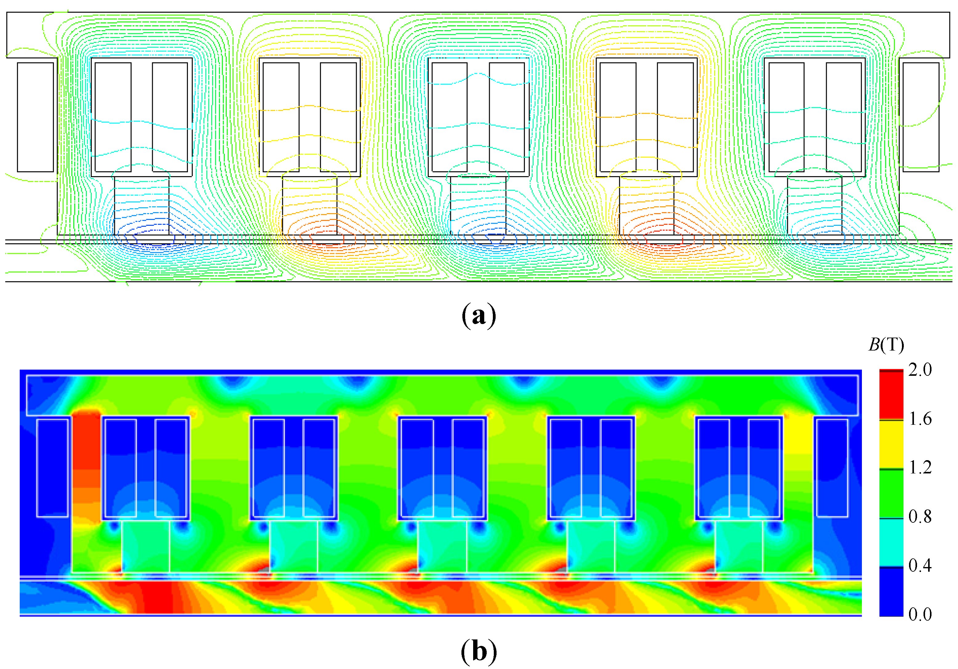
3.1. Static Field Analysis


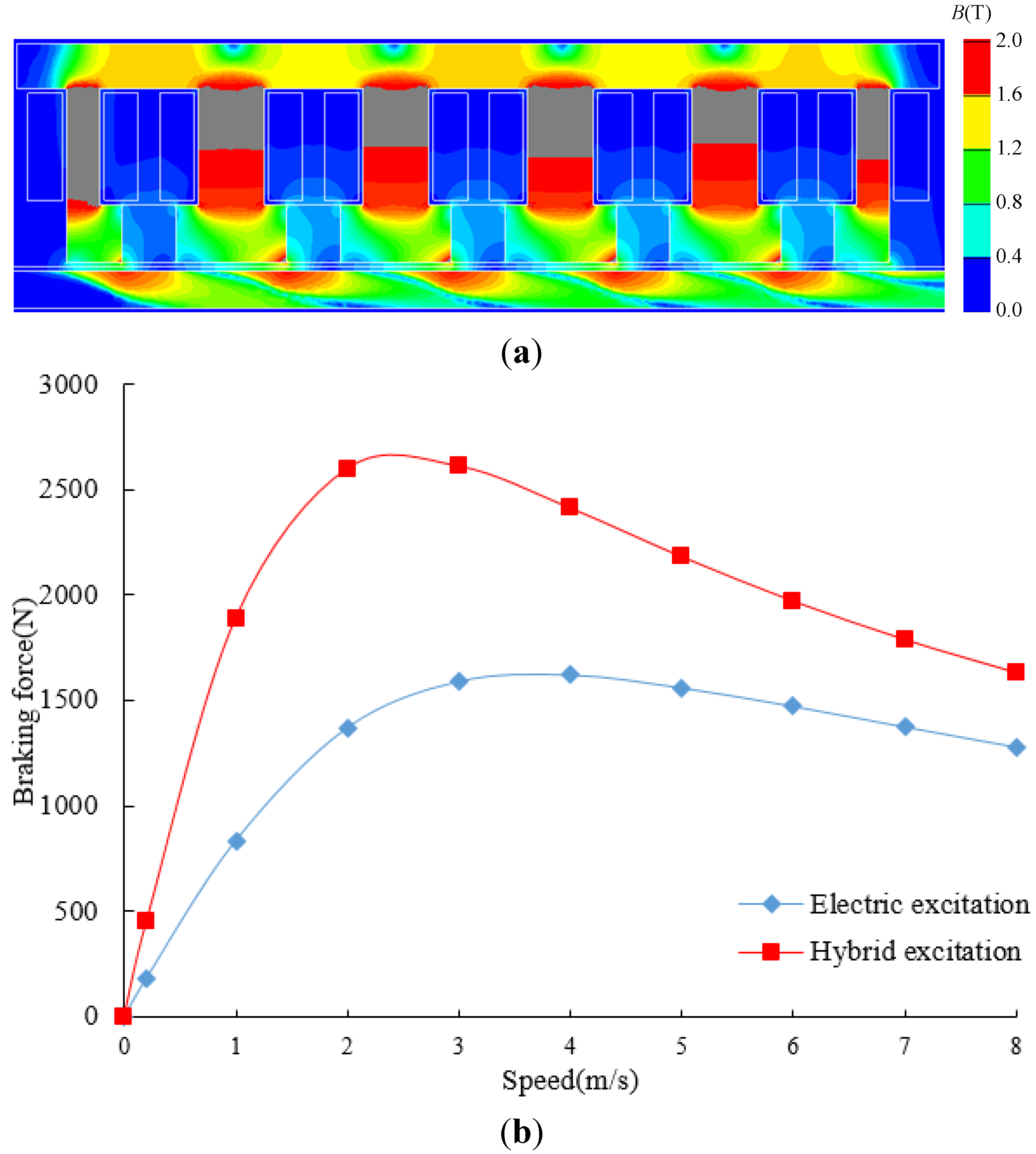
3.2. Braking Force Analysis

- Region 0: primary core.
- Region 1: air gap.
- Region 2: secondary conductor plate.
- Region 3: back iron.
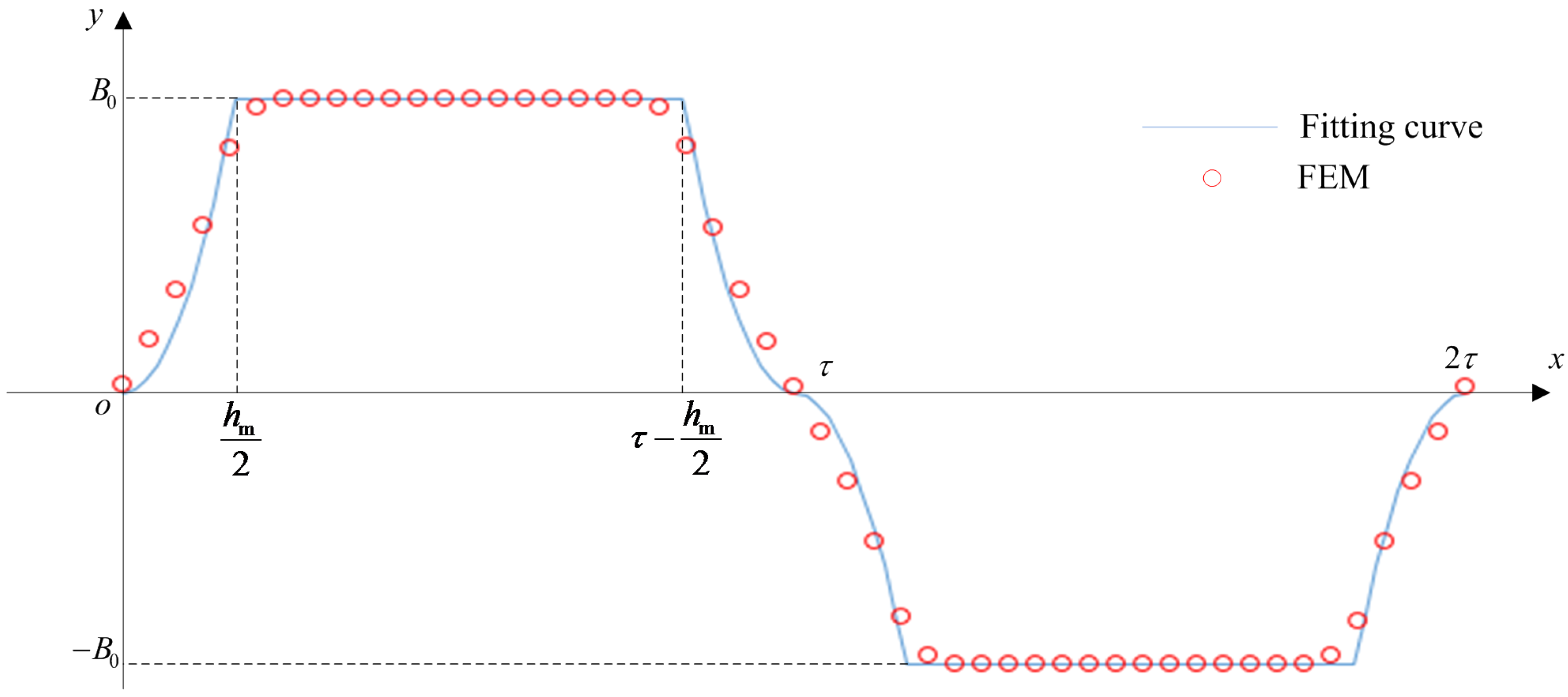
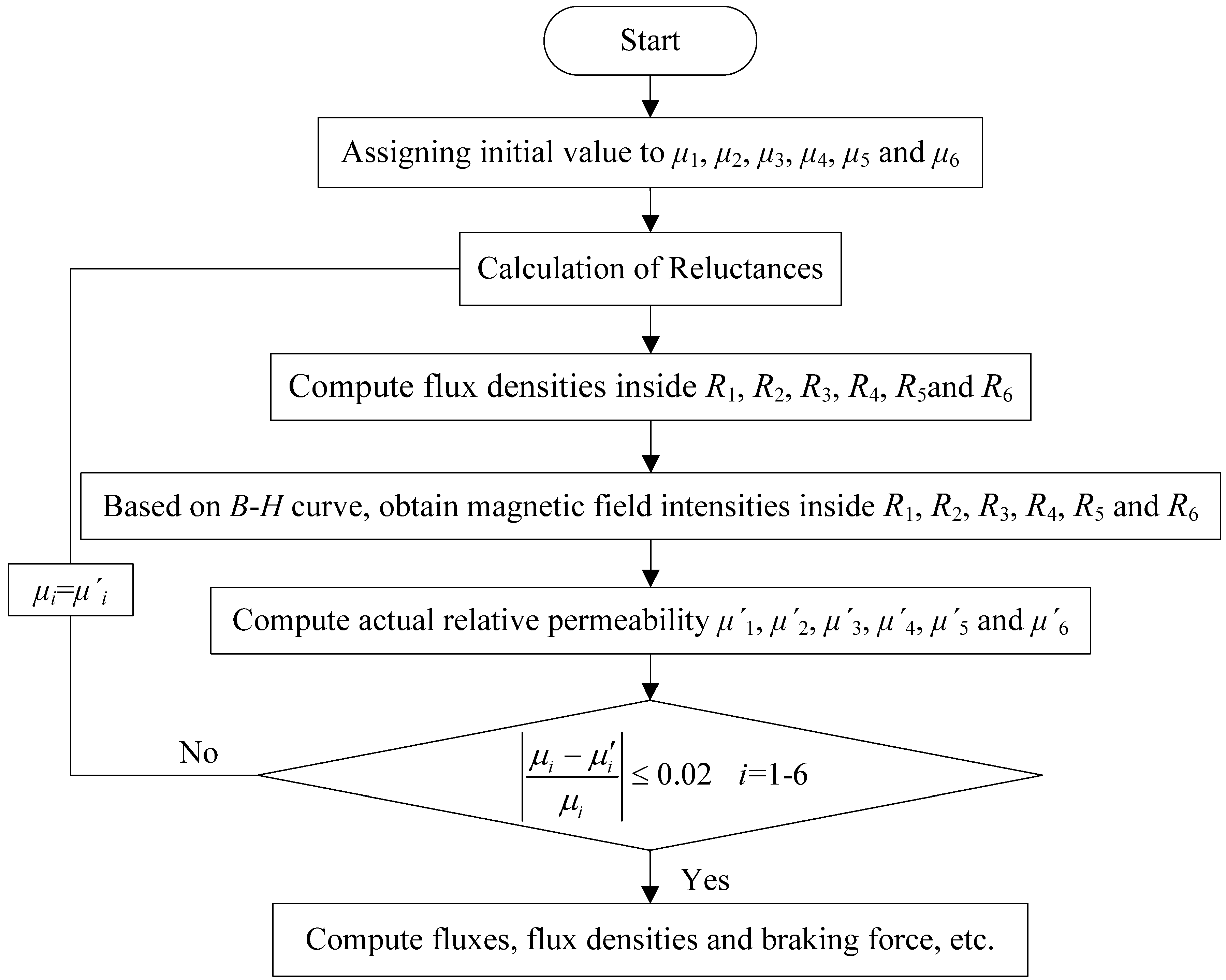
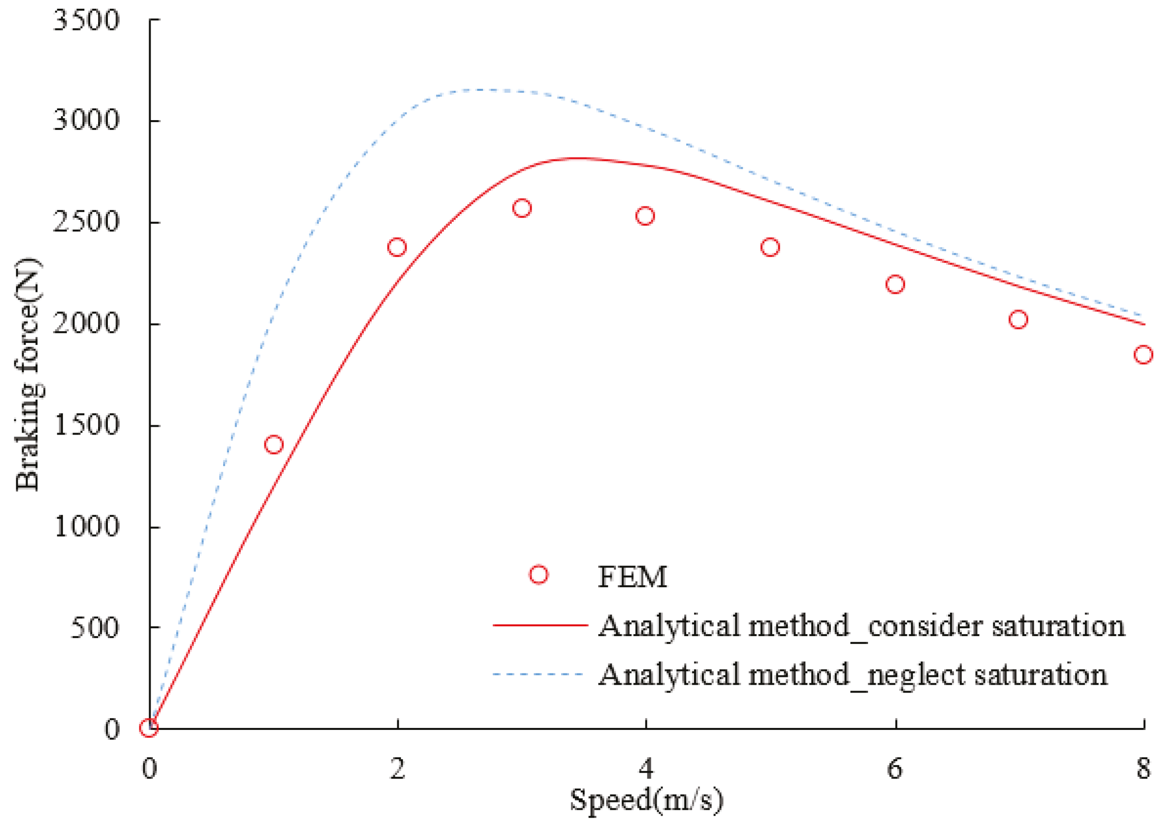
3.3. Consideration of the Nonlinear Magnetization Characteristics of the Iron Core


4. Parameter Analysis and Its Determination

| Symbol | Quantity | Value |
|---|---|---|
| hm | width of the permanent magnet | 18 mm |
| bm | height of the permanent magnet | 10 mm |
| I | excitation current | 14 A |
| N | turns of the excitation winding | 200 |
| L | length of the primary iron core | 200 mm |
| lδ | width of the primary iron core | 100 mm |
| hj | height of the primary core yoke | 11 mm |
| H | height of the primary iron core | 49 mm |
| δ | air gap length | 2 mm |
| τ | pole pitch | 40 mm |
| c | conductor plate thickness | 2 mm |
| hb | back iron thickness | 9 mm |
| bt | tooth width | 16 mm |
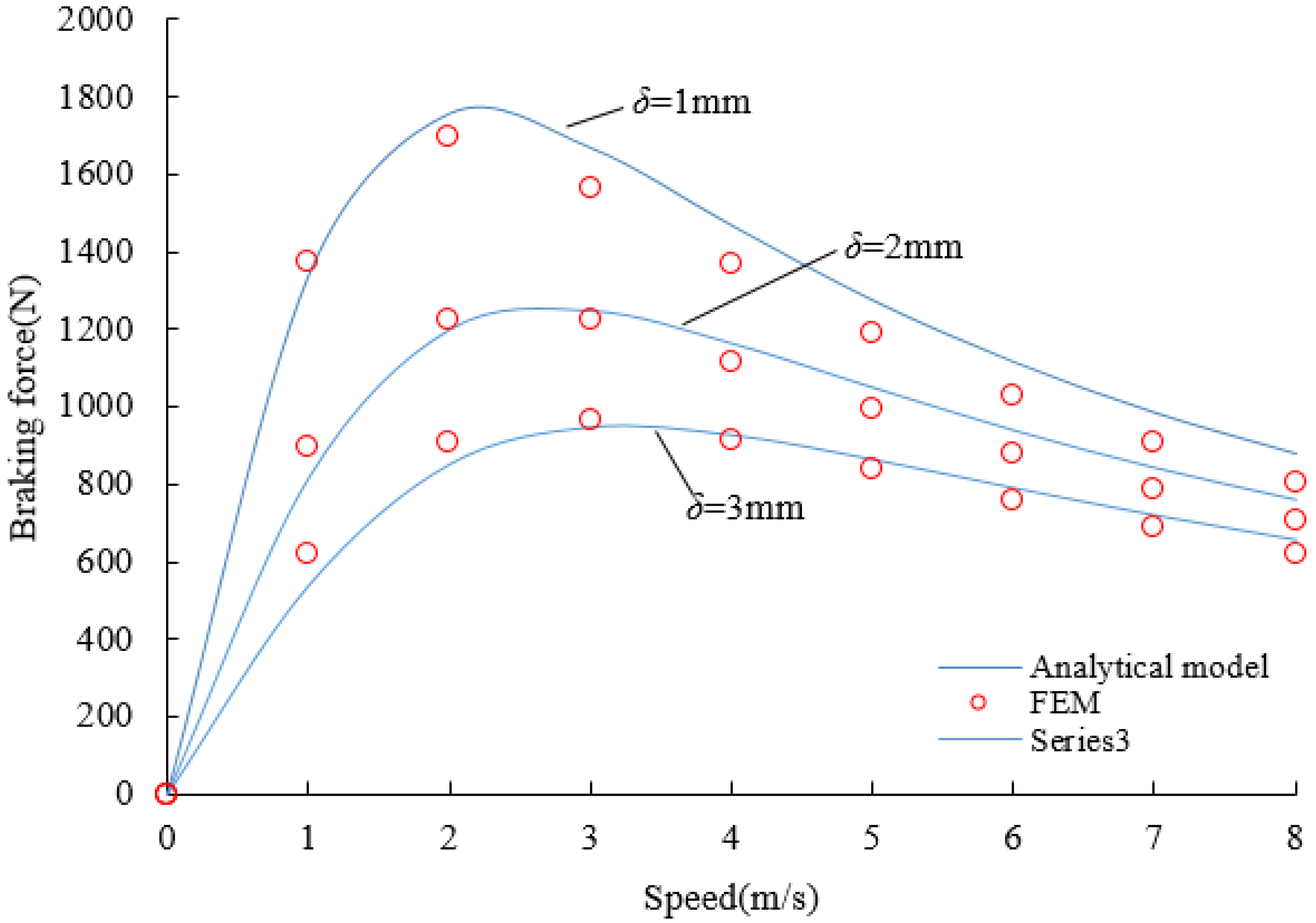
4.1. Influence of the Air Gap Length

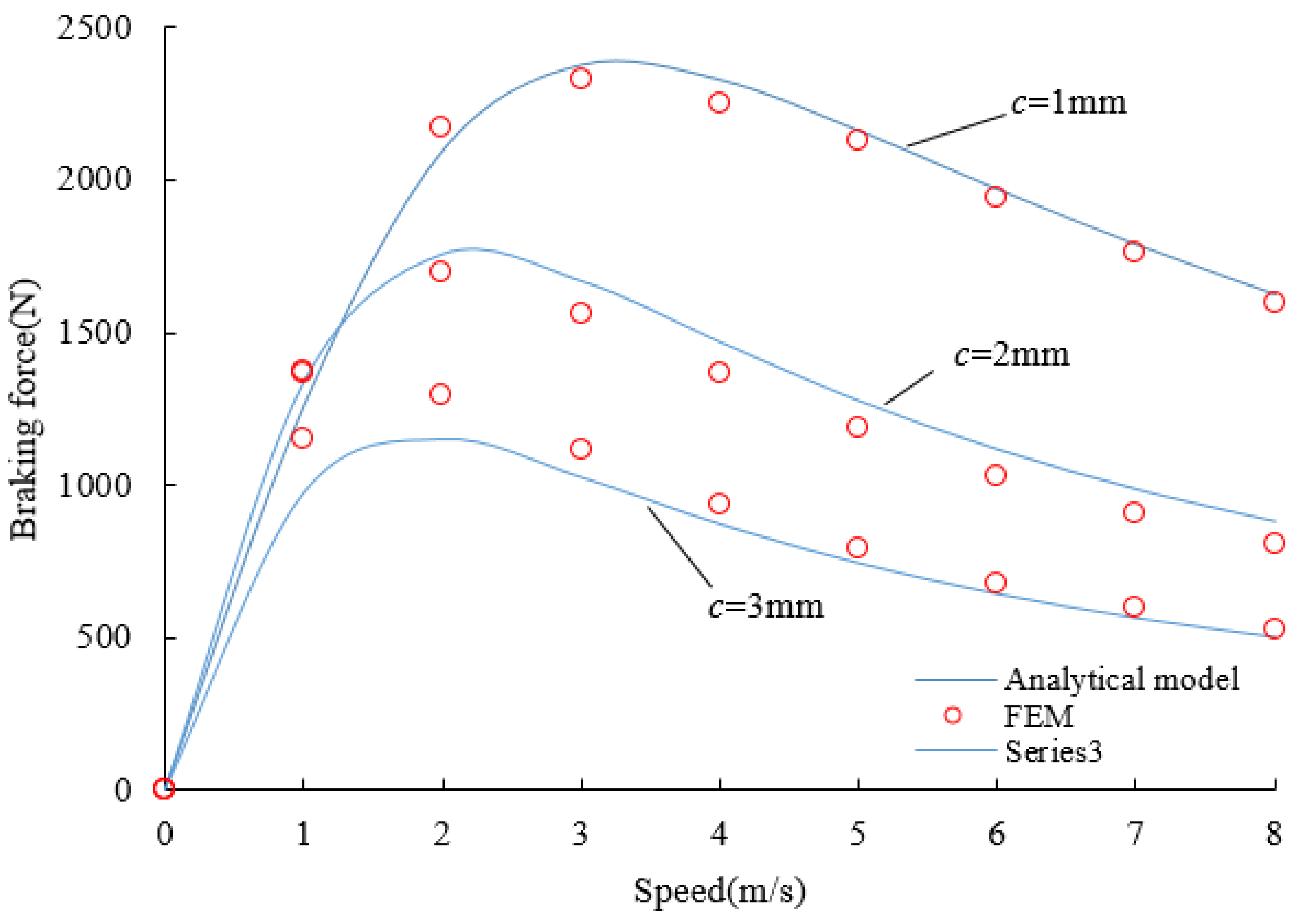
4.2. Influence of the Conductor Plate Thickness

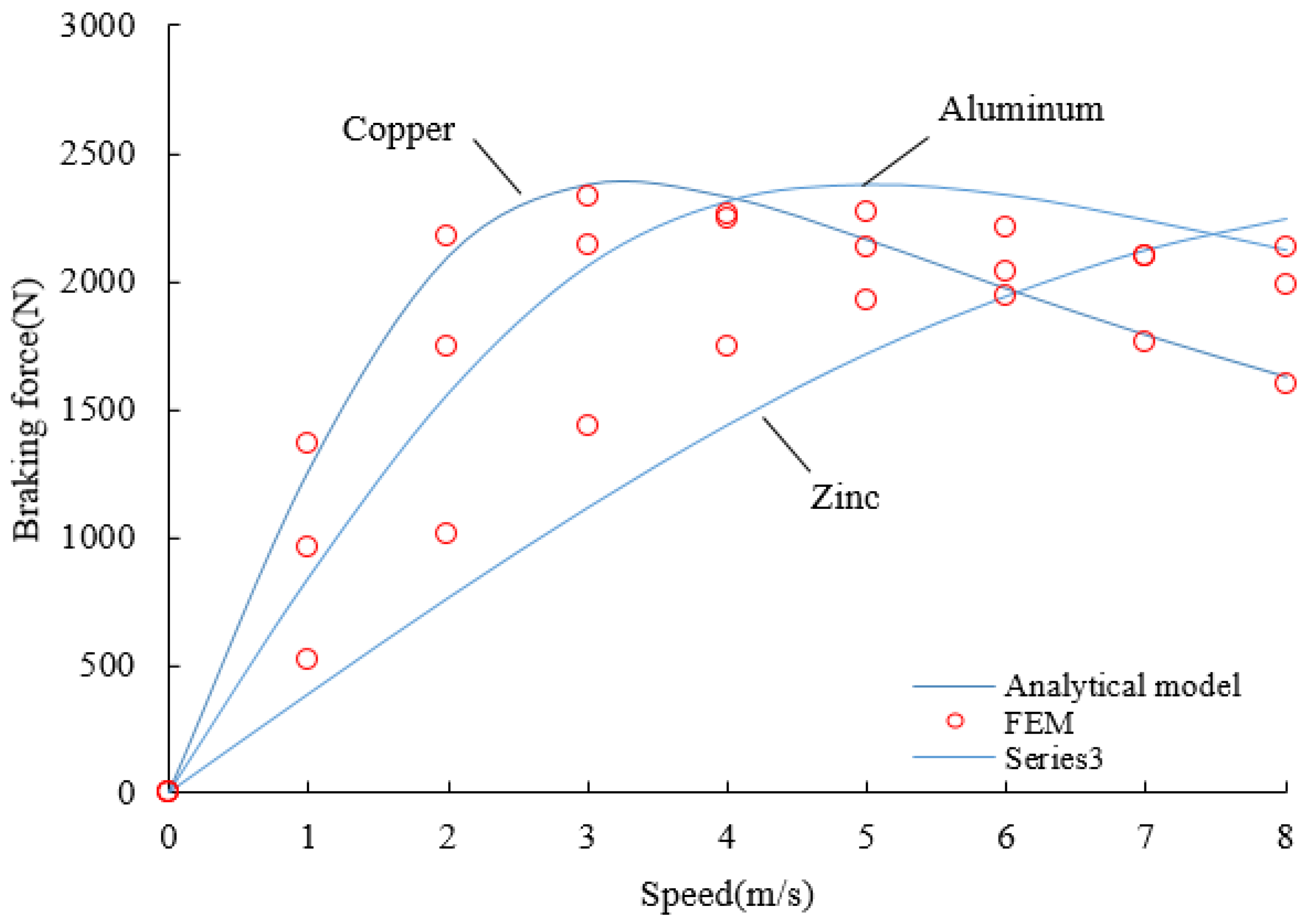
4.3. Influence of the Conductor Material

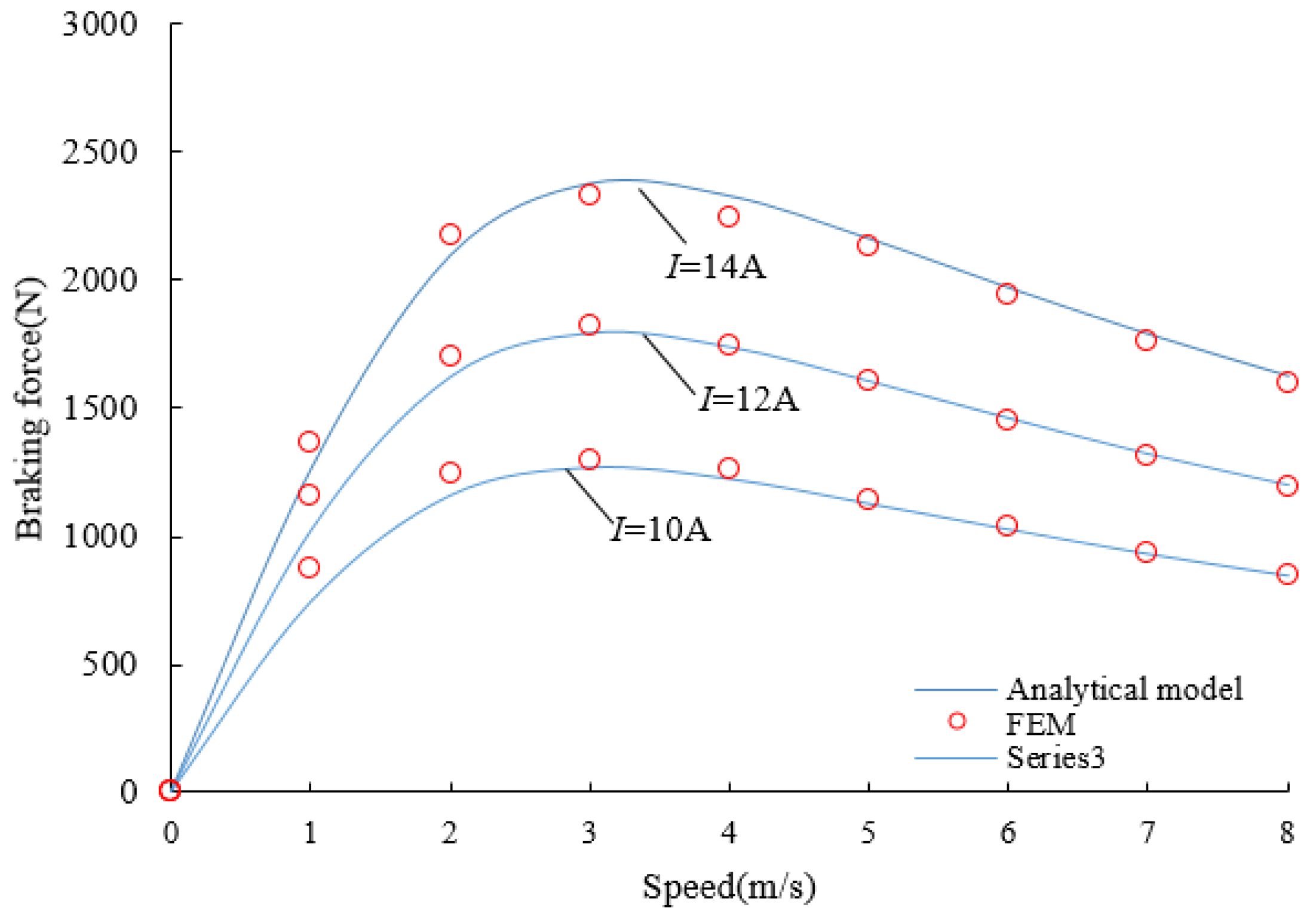
4.4. Influence of the Excitation Current

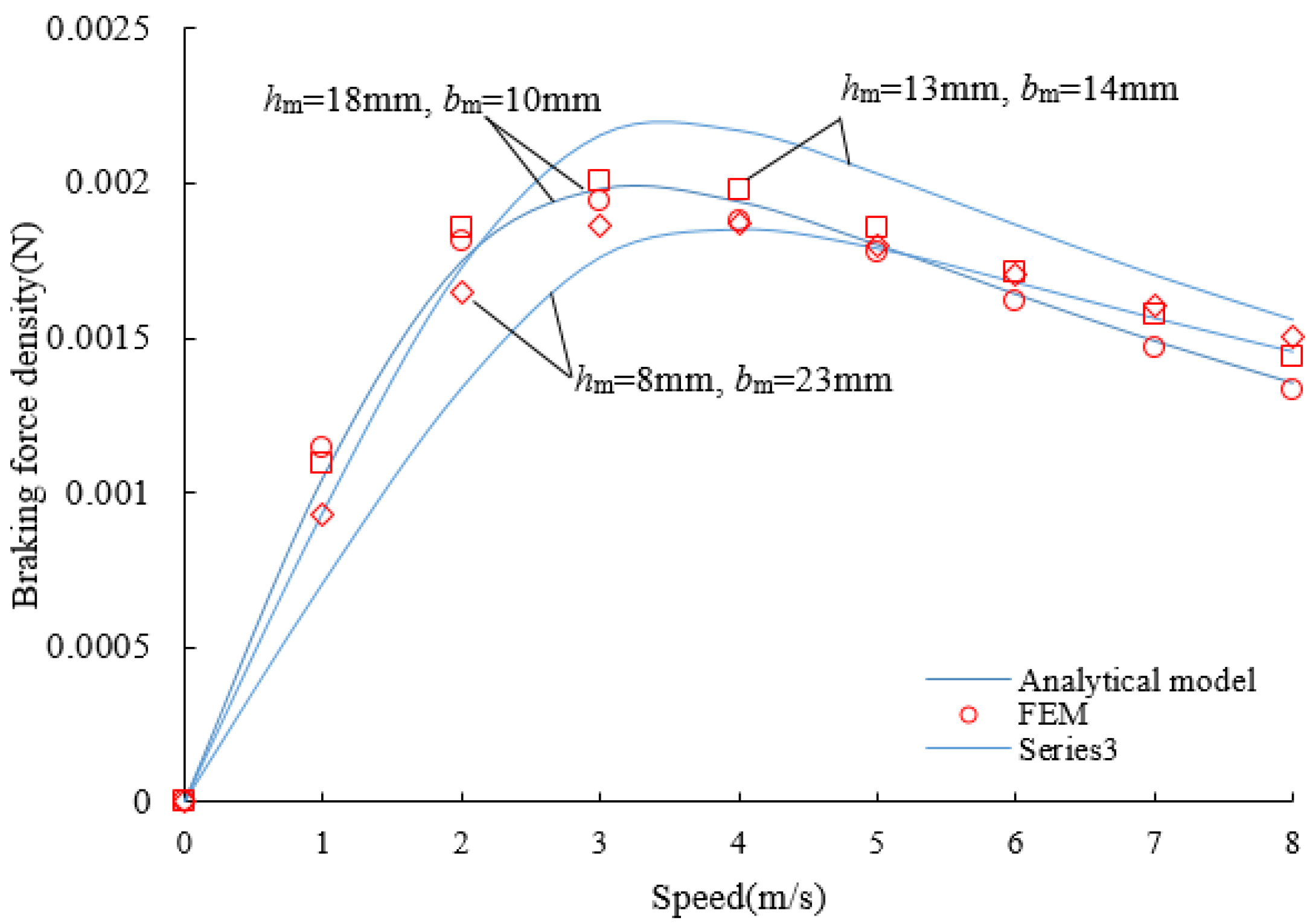
4.5. Influence of the Magnet Dimension

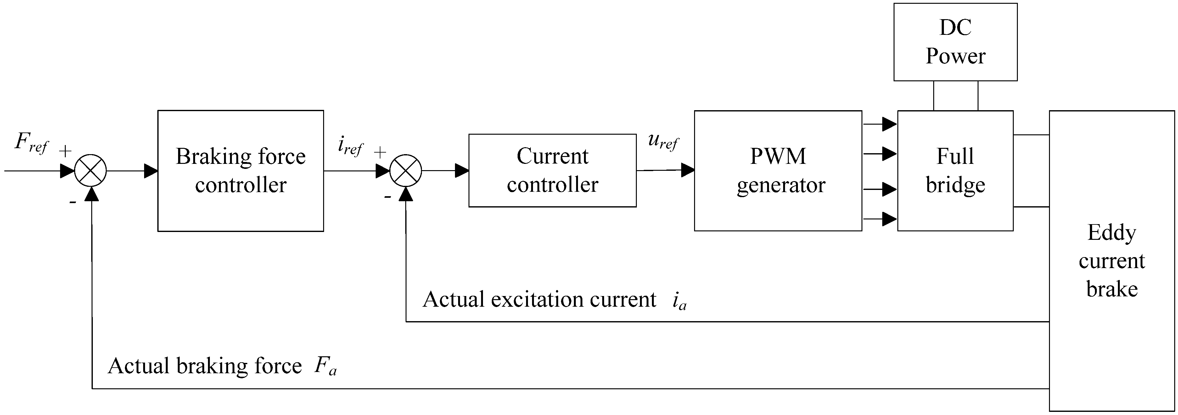
5. Eddy Current Brake Controller

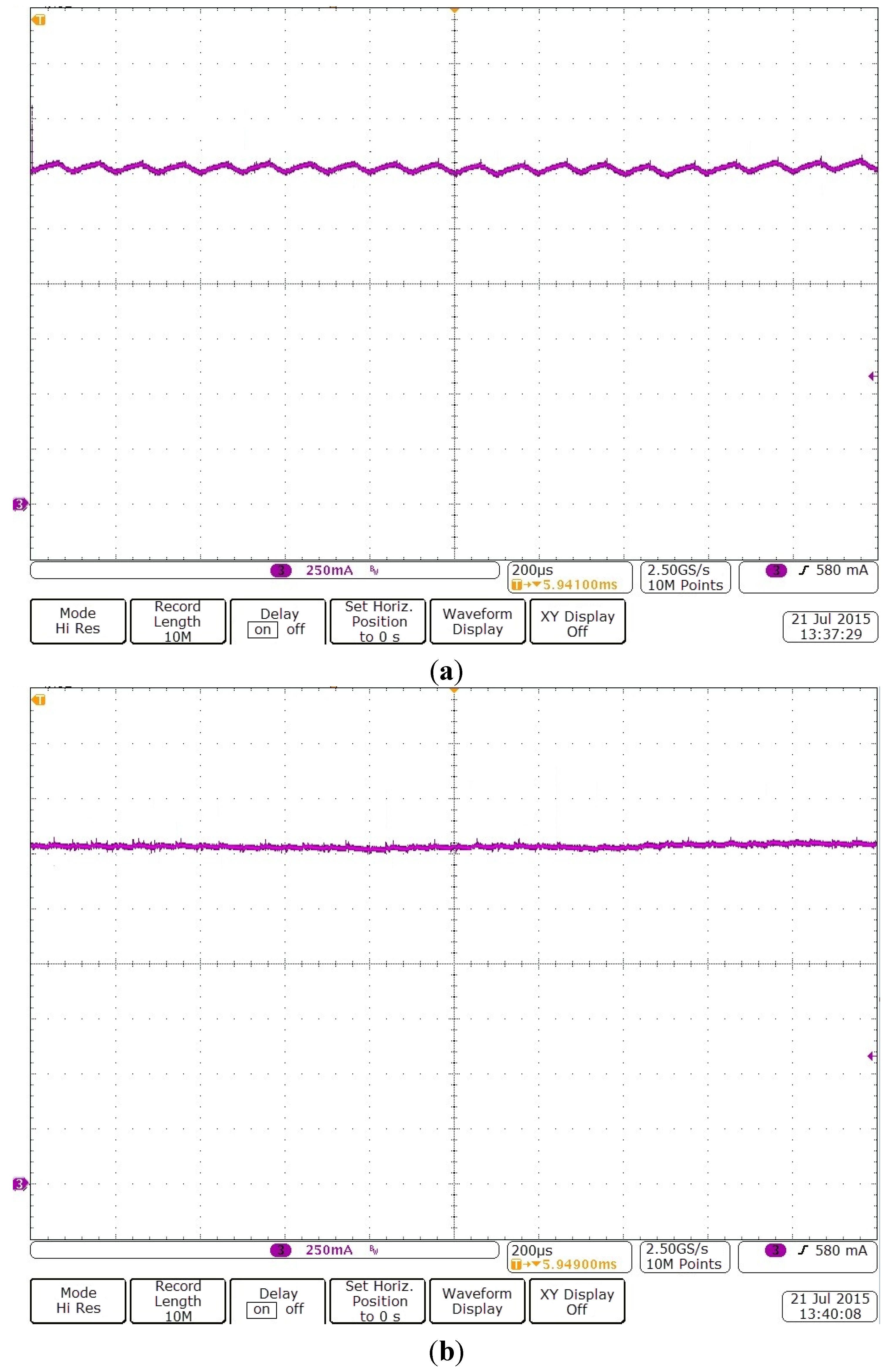
5.1. Current Controller Design
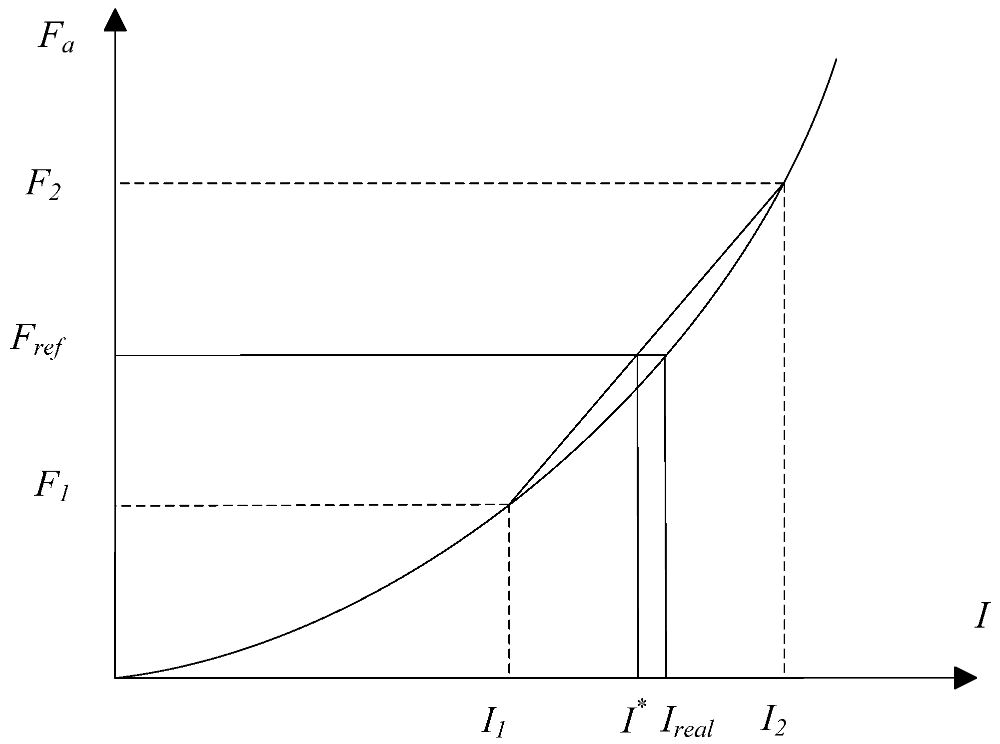
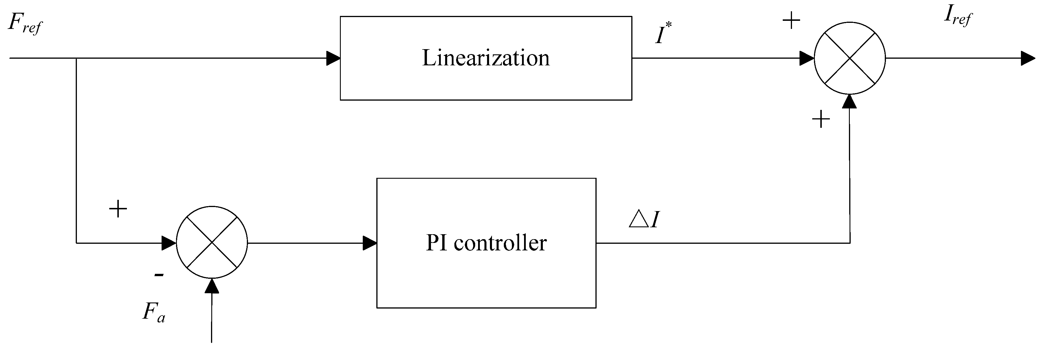
5.2. Braking Force Controller Design


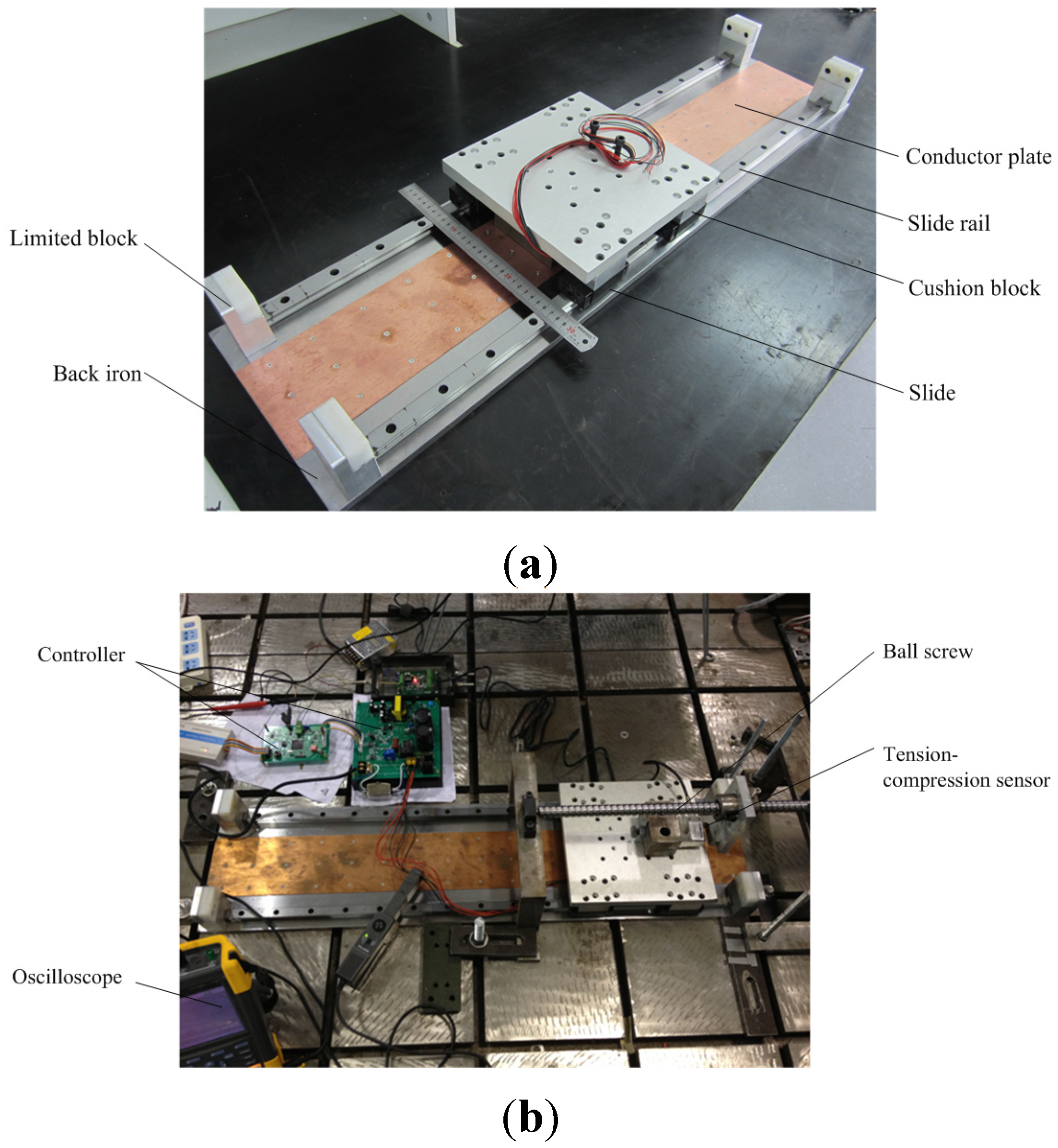
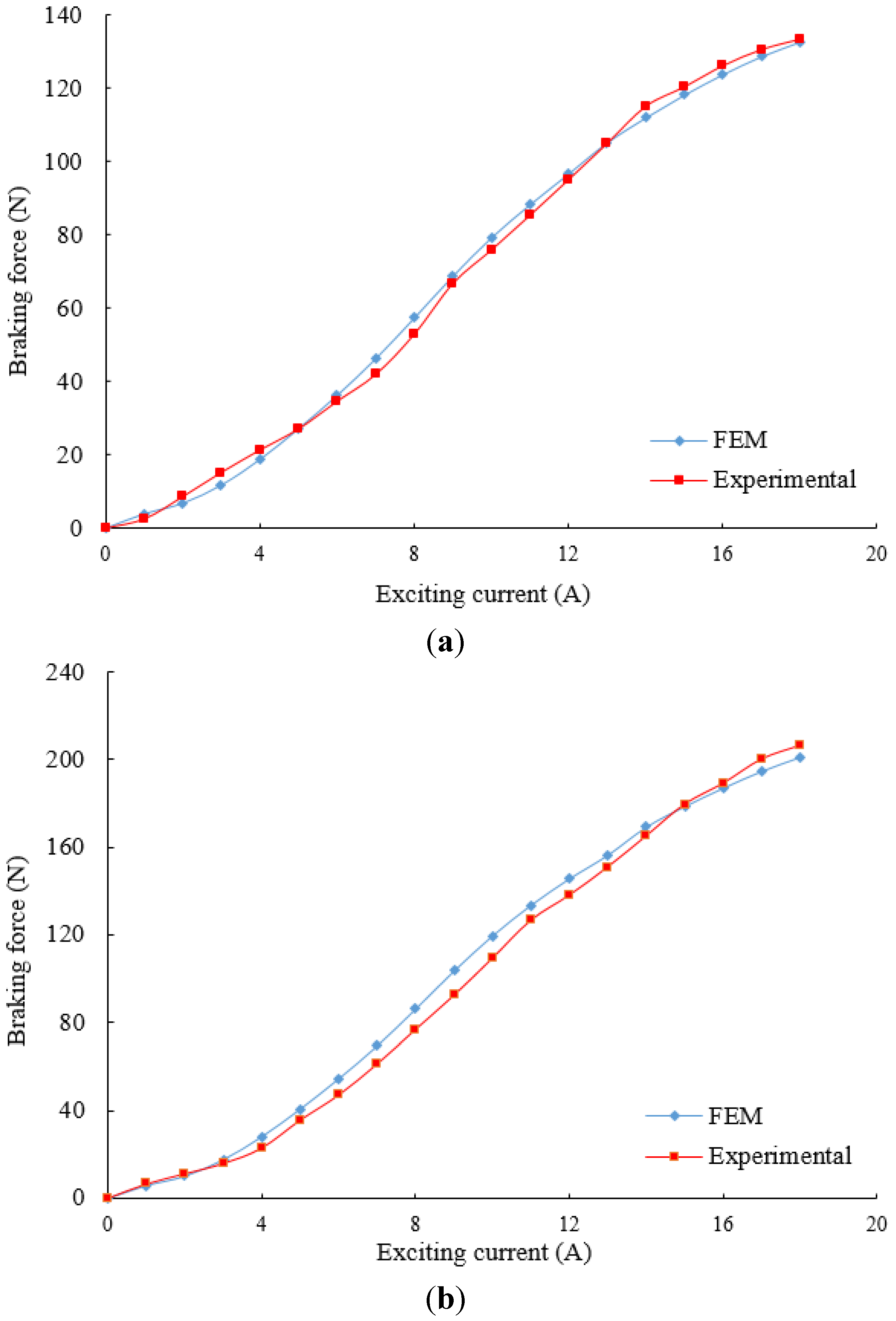
6. Numerical and Experimental Analysis


| Symbol | Quantity | Value |
|---|---|---|
| hm | width of the permanent magnet | 13 mm |
| bm | height of the permanent magnet | 14 mm |
| I | excitation current | 14 A |
| N | turns of the excitation winding | 200 |
| L | length of the primary iron core | 200 mm |
| lδ | width of the primary iron core | 100 mm |
| hj | height of the primary core yoke | 11 mm |
| H | height of the primary iron core | 53 mm |
| δ | air gap length | 1 mm |
| τ | pole pitch | 40 mm |
| c | conductor plate thickness | 1 mm |
| hb | back iron thickness | 9 mm |
| bt | tooth width | 16 mm |


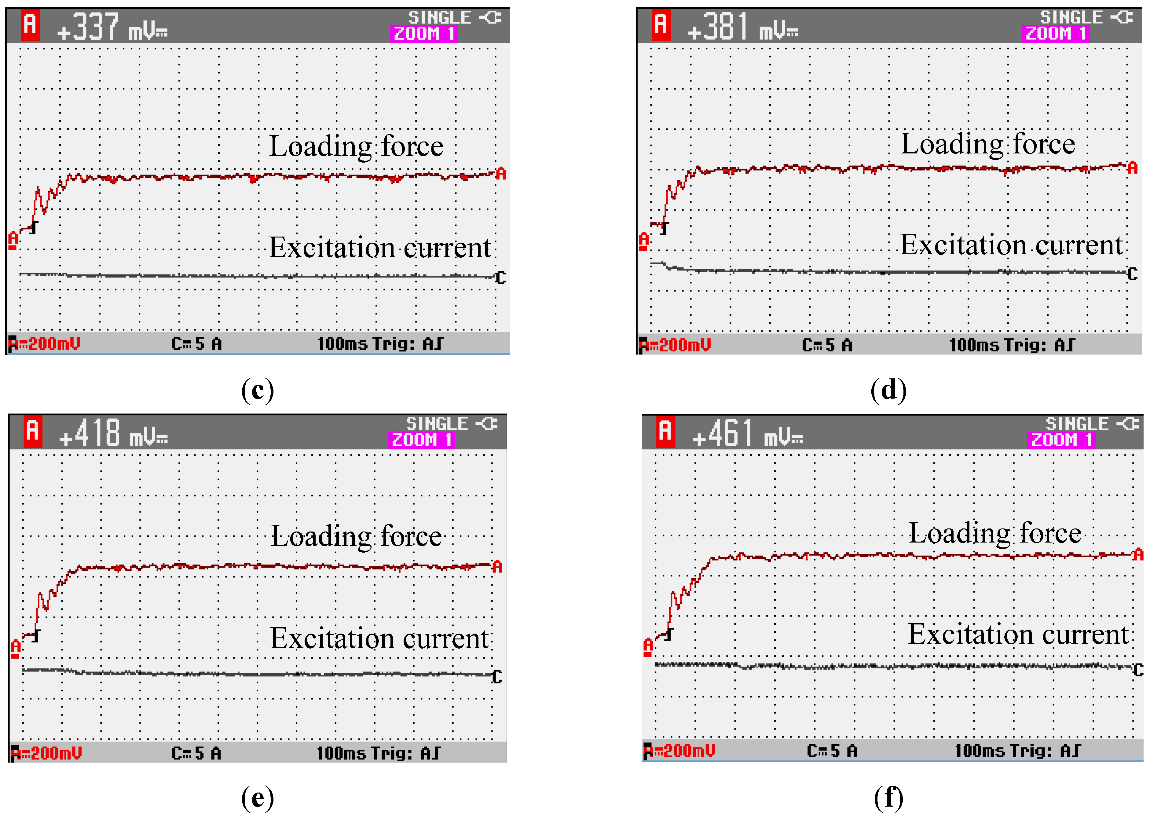
| Objective Braking Force | Measured Value of Output Voltage | Measured Value of Braking Force | Error |
|---|---|---|---|
| 70 N | 337 mV | 67.4 N | 3.7% |
| 80 N | 381 mV | 76.2 N | 4.8% |
| 90 N | 418 mV | 83.6 N | 7.1% |
| 100 N | 461 mV | 92.2 N | 7.8% |
7. Conclusions
Acknowledgments
Author Contributions
Conflicts of Interest
References
- Jang, S.; Lee, S.; Jeong, S. Characteristic analysis of eddy-current brake system using the linear Halbach array. IEEE Trans. Magn. 2002, 38, 2994–2996. [Google Scholar] [CrossRef]
- Sainjargal, S.; Byun, J. Analysis and case study of permanent magnet arrays for eddy current brake systems with a new performance index. J. Magn. 2013, 18, 276–282. [Google Scholar] [CrossRef]
- Hecquet, M.; Brochet, P.; Lee, S.; Delsalle, P. A linear eddy current braking system defined by finite element method. IEEE Trans. Magn. 1999, 35, 1841–1844. [Google Scholar] [CrossRef]
- Gay, S.E. Contactless Magnetic Brake for Automotive Applications. Ph.D. Thesis, Texas A&M University, College Station, TX, USA, 2005. [Google Scholar]
- Wang, P.J.; Chiueh, S.J. Analysis of eddy-current brakes for high speed railway. IEEE Trans. Magn. 1998, 34, 1237–1239. [Google Scholar] [CrossRef]
- Jang, S.; Lee, S. Comparison of three types of permanent magnet linear eddy-current brakes according to magnetization pattern. IEEE Trans. Magn. 2003, 39, 3004–3006. [Google Scholar] [CrossRef]
- Ha, K.; Hong, J.; Kim, G.; Lee, J.; Kang, D. A study of the design for touch free linear eddy current brake. IEEE Trans. Magn. 1999, 35, 4031–4033. [Google Scholar] [CrossRef]
- Ihm, H.; Lee, S.; Ham, S.; Lee, J. The influence of slit construction on the eddy current braking torque considered by 3D FEM analysis. In Proceedings of the International Conference on Electrical Machines and Systems, Wuhan, China, 17–20 October 2008; pp. 444–446.
- Choi, J.; Shin, H.; Park, Y.; Jang, S. Torque analysis of axial flux PM type eddy current brake based on analytical field computations. In Proceedings of the International Conference on Electrical Machines and Systems, Beijing, China, 20–23 August 2011; pp. 1–5.
- Amati, N.; Tonoli, A.; Canova, A.; Cavalli, F.; Padovani, M. Dynamic behavior of torsional eddy-current dampers: Sensitivity of the design parameters. IEEE Trans. Magn. 2007, 43, 3266–3277. [Google Scholar] [CrossRef]
- Lequesne, B.; Liu, B.; Nehl, T.W. Eddy-current machines with permanent magnets and solid rotors. IEEE Trans. Ind. Appl. 1997, 33, 1289–1294. [Google Scholar] [CrossRef]
- Shin, H.; Choi, J.; Cho, H.; Jang, S. Analytical torque calculations and experimental testing of permanent magnet axial eddy current brake. IEEE Trans. Magn. 2013, 49, 4152–4155. [Google Scholar] [CrossRef]
- Canova, A.; Vusini, B. Analytical modeling of rotating eddy-current couplers. IEEE Trans. Magn. 2005, 41, 24–35. [Google Scholar] [CrossRef]
- Mohammadi, S.; Mirsalim, M.; Vaez-Zadeh, S. Nonlinear modeling of eddy-current couplers. IEEE Trans. Energy Convers. 2014, 29, 224–231. [Google Scholar] [CrossRef]
- Li, P.; Ma, J.; Fang, Y. Design and analysis of hybrid excitation rail eddy current brake system of high-speed train. In Proceedings of the IEEE International Conference on Service Operations, Logistics, and Informatics, Beijing, China, 10–12 July 2011; pp. 565–569.
- Edwards, J.D.; Jayawant, B.V.; Dawson, W.R.C.; Wright, D.T. Permanent-magnet linear eddy-current brake with a non-magnetic reaction plate. IEE Proc. Electr. Power Appl. 1999, 146, 627–631. [Google Scholar] [CrossRef]
- Jang, S.; Jeong, S.; Cha, S. The application of linear Halbach array to eddy current rail brake system. IEEE Trans. Magn. 2001, 37, 2627–2629. [Google Scholar] [CrossRef]
- Gay, S.E.; Ehsani, M. Analysis and experimental testing of a permanent magnet eddy-current brake. In Proceedings of IEEE Conference Vehicle Power and Propulsion, Chicago, IL, USA, 7–9 September 2005; pp. 756–765.
- Canova, A.; Vusini, B. Design of axial eddy current couplers. IEEE Trans. Ind. Appl. 2003, 39, 725–733. [Google Scholar] [CrossRef]
- Yazdanpanah, R.; Mirsalim, M. Axial-flux wound-excitation eddy-current brakes: Analytical study and parametric modeling. IEEE Trans. Magn. 2014, 50, 1–10. [Google Scholar]
- Choi, J.; Jang, S. Analytical magnetic torque calculations and experimental testing of radial flux permanent magnet-type eddy current brakes. J. Appl. Phys. 2012, 111. [Google Scholar] [CrossRef]
- Singh, A. Theory of eddy-current brakes with thick rotating discs. Proc. IEE 1977, 124, 373–376. [Google Scholar] [CrossRef]
- Park, M.; Choi, J.; Shin, H.; Jang, S. Torque analysis and measurements of a permanent magnet type Eddy current brake with a Halbach magnet array based on analytical magnetic field calculations. J. Appl. Phys. 2014, 115. [Google Scholar] [CrossRef]
- Srivastava, R.K.; Kumar, S. An alternative approach for calculation of braking force of an eddy-current brake. IEEE Trans. Magn. 2009, 45, 150–154. [Google Scholar] [CrossRef]
- Liu, Z.J.; Vourdas, A.; Binns, K.J. Magnetic field and eddy current losses in linear and rotating permanent magnet machines with a large number of poles. IEE Proc. 1991, 138, 289–294. [Google Scholar] [CrossRef]
© 2015 by the authors; licensee MDPI, Basel, Switzerland. This article is an open access article distributed under the terms and conditions of the Creative Commons Attribution license (http://creativecommons.org/licenses/by/4.0/).
Share and Cite
Kou, B.; Jin, Y.; Zhang, L.; Zhang, H. Characteristic Analysis and Control of a Hybrid Excitation Linear Eddy Current Brake. Energies 2015, 8, 7441-7464. https://doi.org/10.3390/en8077441
Kou B, Jin Y, Zhang L, Zhang H. Characteristic Analysis and Control of a Hybrid Excitation Linear Eddy Current Brake. Energies. 2015; 8(7):7441-7464. https://doi.org/10.3390/en8077441
Chicago/Turabian StyleKou, Baoquan, Yinxi Jin, Lu Zhang, and He Zhang. 2015. "Characteristic Analysis and Control of a Hybrid Excitation Linear Eddy Current Brake" Energies 8, no. 7: 7441-7464. https://doi.org/10.3390/en8077441