Article

Comparative Study of a Fault-Tolerant Multiphase Wound-Field Doubly Salient Machine for Electrical Actuators

Aero-Power Science Technology Center, Nanjing University of Aeronautics and Astronautics, Nanjing 210016, China
*
Author to whom correspondence should be addressed.
Energies 2015, 8(5), 3640-3660; https://doi.org/10.3390/en8053640
Submission received: 3 November 2014 / Revised: 19 March 2015 / Accepted: 20 April 2015 / Published: 29 April 2015
(This article belongs to the Special Issue Electrical Power and Energy Systems for Transportation Applications)

Abstract

:
New multiphase Wound-Field Doubly Salient Machines (WFDSMs) for electrical actuators with symmetric phases are investigated and compared in this paper. With a comparative study of the pole number and pole arc coefficient, the salient pole topology of the three-phase, four-phase, five-phase, and six-phase WFDSMs with little cogging torque is presented. A new winding configuration that can provide symmetrical phases for the multiphase WFDSMs is proposed. Suitable fault-tolerant converters for the multiphase WFDSM are presented. With the simulated results in terms of the pole topology, flux linkage, back EMF and converters, it can be concluded that the pole numbers of the new five-phase WFDSM are very large. The high accuracy position sensors should be required to make the five-phase WFDSM commutate frequently and accurately at a high speed. The four-phase and the six-phase WFDSM can be divided into two isolated channels, and both of them have a good performance as a fault-tolerant machine. All of the investigations are verified by finite element analysis results.

1. Introduction

Today conventional aircraft are characterized by complex hydraulic nets. In order to reduce the weight of the pipelines, cylinders, pump, valves and switches of the hydraulic system, the aircraft is adopting more and more electrical systems in preference to others. Now, researchers and engineers have proved that electrical actuators can be used to reduce or to remove the traditional hydraulic, and mechanical systems in the next few years [1]. The more electric aircraft approach is widely discussed in the technical literature, which includes the following three main drives [2]:
  • The starter-generator for the engine;
  • The electrical actuators for the flight control;
  • The electric machines for the fuel pump.
There are many different types of actuators in a conventional aircraft [3], such as the actuators in the wings and in the tail. In the hydraulic actuation system, the flight control is realized by a hydraulic pump and a hydraulic motor, several fluid pipelines and hydraulic actuators. Now, more and more electric machines are being used to replace or assist the hydraulic actuation system. For example, in the Boeing 787, the spoilers and the horizontal stabilizer flight controls are driven by electric machines in order to guarantee the operation in the case of a hydraulic failure.
A literature review reveals that several types of machine can be used as a drive motor for electrical actuators [4]. Among them, PM machines and Switched Reluctances Machines (SRMs) were abundantly studied in the past years, because of their very-high power density.
In [5], a five-phase PM brushless machine was developed for an aircraft flap actuator application, and the machine can endure the fault of one or two open phases or a phase short circuit. In [6], a PM fractional slot machine was designed, because the fractional slot windings have low mutual inductances between phases, which meet the magnetic isolation demands of phase windings for multiphase fault-tolerant PM synchronous machines [7]. Such fault-tolerant PM machines were also studied in [8,9].
It is necessary to remark that the actuators of an airplane have to work in very harsh ambient conditions, with temperature variations from −60 °C to +70 °C and the air pressure varies from almost 0 to 1 bar [2]. This harsh environment puts forward higher requirements for high performance PM materials. Furthermore, many of the electrical actuators care little about the torque ripple because the noise of the airplane is very high. Therefore, switched reluctances machines were investigated to drive the actuators in [10,11].
The Wound-Field Doubly Salient Machine (WFDSM) has the same rotor as the SRM that will not suffer from faults of the PM materials or brush faults of the wound-field synchronous motors. The WFDSM is derived from a doubly salient PM machine (DSPM) [12] by using field windings instead of permanent magnet excitation [13]. The WFDSM provides the excitation flux by the DC field windings instead of the PMs. Therefore, the output torque and speed can be adjusted by the field winding and phase windings. What’s more, the phase windings of the WFDSM are isolated from each other, and it has low mutual inductances between phases, which reduces the negative influence of the faulty phase. It has broad application prospects in the fields that care little about the torque ripple, such as mining machinery, electrical actuators, and starter-generators.
For example, a WFDSM with two-section twisted-rotor was developed as a starter-generator for aerospace applications [14]. Recently, some new three-phase WFDSMs with new winding arrangements have been developed to take the place of traditional electric machines [15,16]. In the energy conversion area, a WFDSM worked as a DC generator was equipped in an EV range extender [17]. A prototype of a 24/32-pole WFDSM was developed as a low speed wind turbine generator [13].
Multiphase machines with more than three phases can be applied for high reliability applications because they can still run even with one or two open-circuited phases [18]. To improve the reliability of the WFDSM, a traditional four-phase WFDSM was studied in [17], which was similar to the 8/6-pole DSPM described in [19]. A five-phase WFDSM was developed as a generator in [20], which showed that it had good fault-tolerant characteristics. Therefore, the multiphase WFDSM is very suitable to be designed as a fault-tolerant machine.
However, the four-phase and the five-phase WFDSMs discussed above are traditional WFDSMs with their field windings wound around four and five stator poles, respectively. They have the disadvantage of phase asymmetry. The phase asymmetry of the three-phase WFDSM is not obvious, but we found that the phase asymmetry will increase with the number of phases. It was considered that the WFDSM cannot be designed with six phases, and there have been no reports of six-phase WFDSMs until now.
In this paper, new multiphase WFDSMs for electrical actuators with symmetric phases will be investigated and compared. With the comparative study of the poles number and pole arc coefficient, the salient pole topology of the WFDSMs that have little cogging torque will be presented. A new winding configuration to provide symmetrical phases will be proposed. Suitable fault-tolerant converters for the multiphase WFDSMs will be presented. With the comparison in terms of the pole topology, flux linkage, back EMF and converters, comparative conclusions will be proposed to select a multiphase WFDSM for electrical actuators.

2. Comparative Study of the Salient Pole Topology

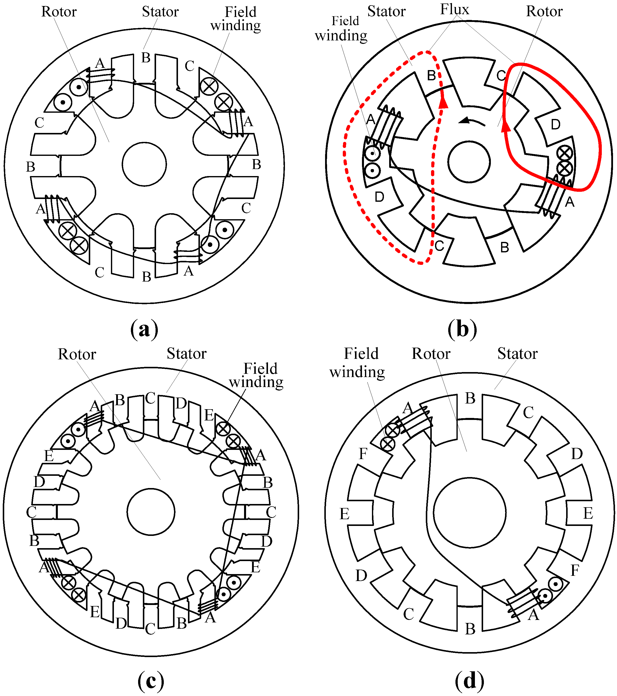
2.1. Salient Pole Number

There is a wide range of possible combinations of the stator poles and the rotor poles. Nevertheless, only few combinations are suitable to be selected. To outline the pole combinations, the principle of the salient pole number should be studied first.
As we can see from the traditional three-phase WFDSM in Figure 1a, there are 6N stator poles and 4N rotor poles, where N is the number of element machines. Each phase coil is wound around one stator pole, and the field coils are wound around every three stator poles [17].
So the first law of the stator poles can be written as:
ps = mi
where ps should be an even number, and it stands for the number of stator poles. m is the phase number and i is a positive integer. If ps is an odd number, the north field winding will not be equal to the south field winding, and the machine will generate an unbalanced magnetic force. Let pr be the rotor poles number. The mechanical angle of one period βr can be obtained as:
β r = 360 ° p r
Figure 1. Structure of the three-phase and multiphase DSG. (a) 12/8-pole three-phase of WFDSM; (b) 8/6-pole four-phase; (c) 20/16-pole five-phase; (d) 12/10-pole six-phase.
Energies 08 03640 g001
The mechanical angle of each stator pole βs is:
β s = 360 ° p s
Because the adjacent poles have the adjacent phase windings, the mechanical angle between two phases can be expressed as:
β δ = 360 ° m 1 p r
and the difference between βr and βs is ±βδ:
β r β s = ±β δ
From Equations (2)–(5), we can get the second law of the rotor and the stator poles:
p s p r = m m ± 1
When m = 3, the elementary machine of three-phase WFDSM has six stator poles and four or eight rotor poles, which is called 6/4-pole machine or 6/8-pole machine [14]. In the same way, the elementary machine of a traditional four-phase WFDSM has an 8/6-pole or 8/10-pole structure. Table 1 gives the pole combinations of the WFDSM with different phases.
Table 1. The poles combinations of the WFDSM.
Phase numberStator polesRotor polesExample
Three-phase6N4N or 8N12/8
Four-phase4N3N or 5N8/6
Five-phase10N8N or 12N20/16
Six-phase6N5N or 7N12/10

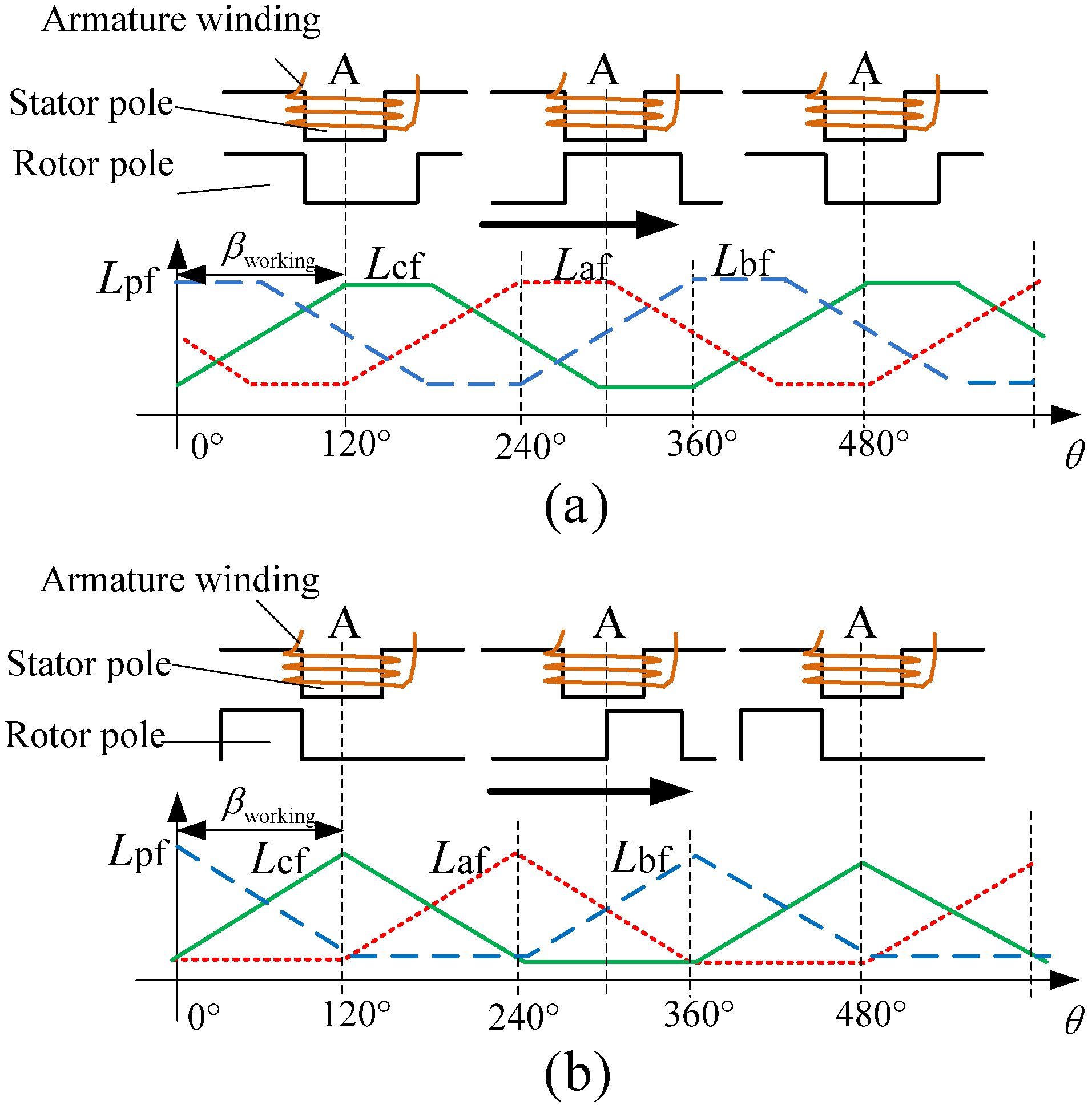
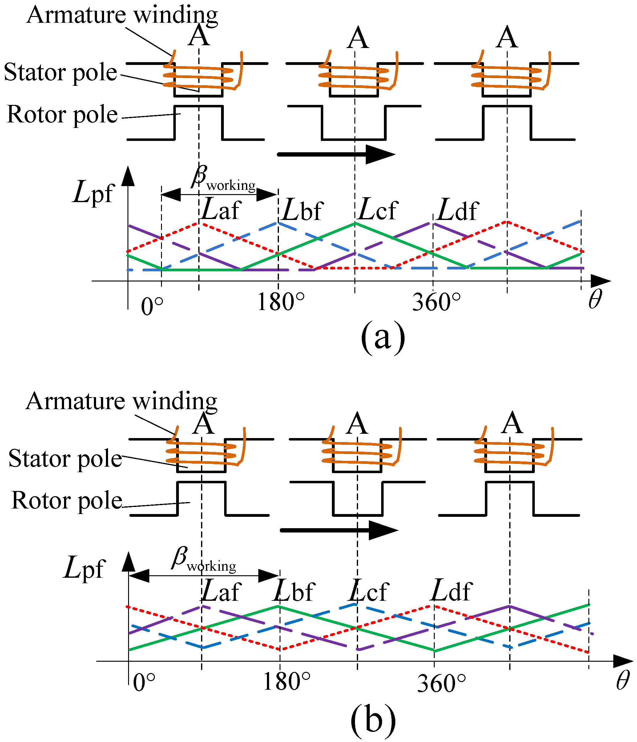
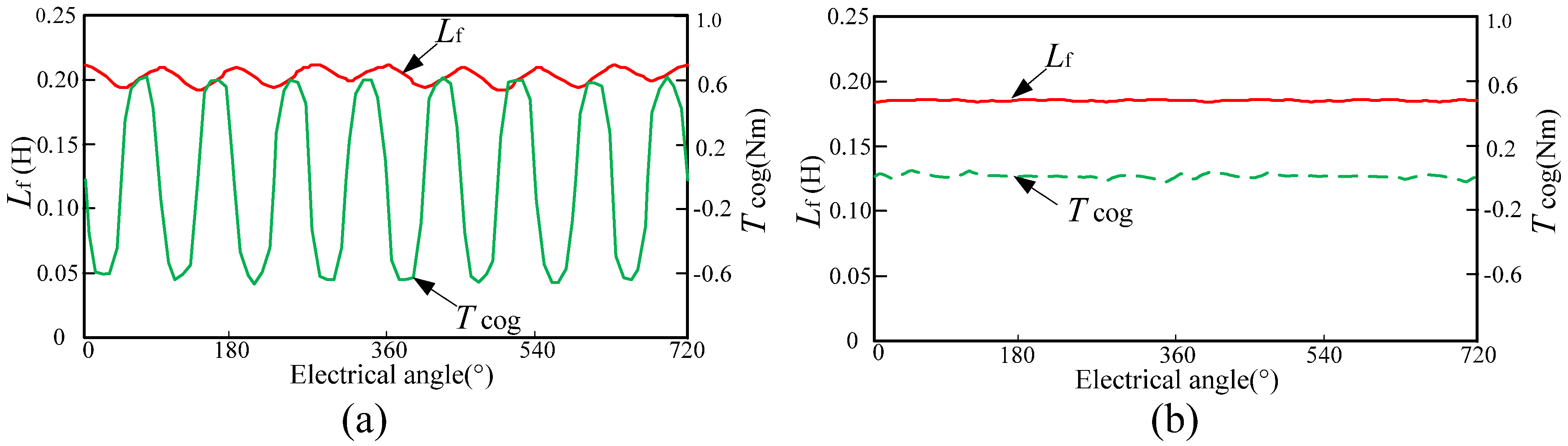
2.2. Pole Arc Coefficient

The WFDSM stator is equipped with both field coils and phase coils. The self-inductance of the phase winding and the field winding change with the rotor positions and the pole arcs [21,22]. If the pole arc is not well-designed, the machine will generate torque ripples because the reluctance and the flux of the field winding will change with the rotor position [23]. In order to minimize the cogging torque caused by the mutative reluctance of the field winding, the self-inductance of the field winding should be constant when the rotor rotates. Overall, the increasing phase number should be equal to the decreasing phase number.
For the common inner-rotor motor, the rotor pole number is usually less than the stator pole number. Hence the rotor pole is generally wider than the stator pole. As the narrow pole of the stator and the rotor determines the increasing or decreasing mechanical angle of the phase inductance, the increasing mechanical angle of the phase inductance can be described as:
β working = 360 ° p s α s
where αs is the stator pole arc coefficient, which is the proportion of the stator pole arc length lt and the pole pitch lp.
α s = α s = l t l p
Let the electrical angle of one phase voltage waveform be θ:
θ = 360 ° p s α s p r = x 180 ° m
where x is the phase number that has a mutative self-inductance at any time, and x ≤ m. If x is large, there will be more phases that can output torque or voltage, and the fault-tolerant ability of the machine will be strong. Because the phase number with increasing inductance should be equal to the phase number with decreasing inductance, it can be concluded that x should be an even number.
For the three-phase WFDSM, while ps/pr = 3/2, θ = 120°. We can draw from Equation (7) and Equation (8) that:
α s = p s 3 p r
Therefore, to make the machine have no cogging torque, reluctance and flux of the field winding the pole arc coefficient of the three-phase WFDSM αs is equal to 0.5.
While ps > pr, the rotor pole width is not generally thinner than the stator pole width. For the three-phase WFDSM, the mutual inductances of the field winding and the phase windings Lpf are shown in Figure 2. When αr = 0.5, the machine can be easily controlled by a BLDC controller, because one period can be divided into six equal parts like a BLDC machine. When αr = 0.333, the machine can output a large torque because the rotor poles and the stator poles are monospaced and the leakage flux is small. Overall, the stator and the rotor pole arc coefficient should comply with αs = 0.5 and αr = 0.5 or 0.333.
Figure 2. Lpf of the three-phase WFDSM with different αr. (a) αr = 0.333; (b) αr = 0.5.
Energies 08 03640 g002
It can be concluded that the pole arc coefficients of three-phase WFDSM should comply with Equation (11):
p s p r = 3 2 α s 0.5 α r 0.333  or  0.5 p s p r = 3 4 α s 0.25 α r 0.333  or  0.5 }
However, the four-phase WFDSM should not be designed with αr = 0.5. As we can see from Figure 3, if αr = 0.5, there will be three changing inductances at any time, x = 3. With this structure, the reluctance of the field winding will change with the position of the rotor, which will generate a big cogging torque, as well as field winding back EMF.
In order to solve the problem of changeable field reluctance, a new four-phase WFDSM is proposed, whose pole arc coefficient complies with Equation (15):
p r p s = 3 4 α s 0.667 α r 0.5 p r p s = 5 4 α s 0.4  α r 0.5 }
Figure 3. Lpf of the four-phase WFDSM with different αr. (a) αs = 0.5, αr = 0.375; (b) αs = 0.667, αr = 0.5.
Energies 08 03640 g003
For this new machine, there are two increasing phase inductances and two decreasing phase inductances at any time, as shown in Figure 3b. The field inductance is steady, and it will not generate cogging torque. The phase voltage waveform electrical angle of this machine is 180°, and the phase number with mutative inductance at any time x = 4. Therefore, all of the four-phase windings can output torque at any time, which improves the fault tolerance of the machine.
Similarly, we can also deduce the pole arc coefficient of the other multiphase WFDSM, since the phase voltage waveform electrical angle of the five-phase WFDSM is 144°, and the angle of the six-phase WFDSM is 120°. In short, it can be newly concluded that the pole arc coefficient of the multi-phase WFDSM should comply with Equation (13).
In short, to reduce the torque ripple caused by the field winding of multi-phase WFDSM, the stator poles, rotor poles and pole arc should follow topology criteria as shown in Equations (1), (6) and (13).
The three pieces of topology criteria not only give a design basis for the WFDSMs with less than six phases, they can also be used to design PM doubly salient machines and hybrid excitation doubly salient machines. What is more, these topology criteria also provide a derivation example for the WFDSMs with more than seven phases.
three phase p s p r = 3 2 α s 0.5   α r 0.333 or  0.5 three phase p s p r = 3 4 α s 0.25  α r 0.333 or  0.5 four phase    p s p r = 4 3 α s 0.667  α r 0.5 four phase    p s p r = 4 5 α s 0.4   α r 0.5 five phase    p s p r = 5 4 α s 0.5   α r 0.4 five phase    p s p r = 5 6 α s 0.333 α r 0.4 six phase    p s p r = 6 5 α s 0.4   α r 0.333 six phase    p s p r = 6 7 α s 0.571 α r 0.333 }
Because the pole numbers and the switches of the converter increase with the phase number, the WFDSM with more than six phases is not suitable to be applied because of the weight and the cost of the converter is unacceptable, as well as the pole number. Therefore, their application prospects are not as broad as those of WFDSMs with less than six phases, because they are too complicated. This paper focuses on the WFDSMs with less than seven phases.

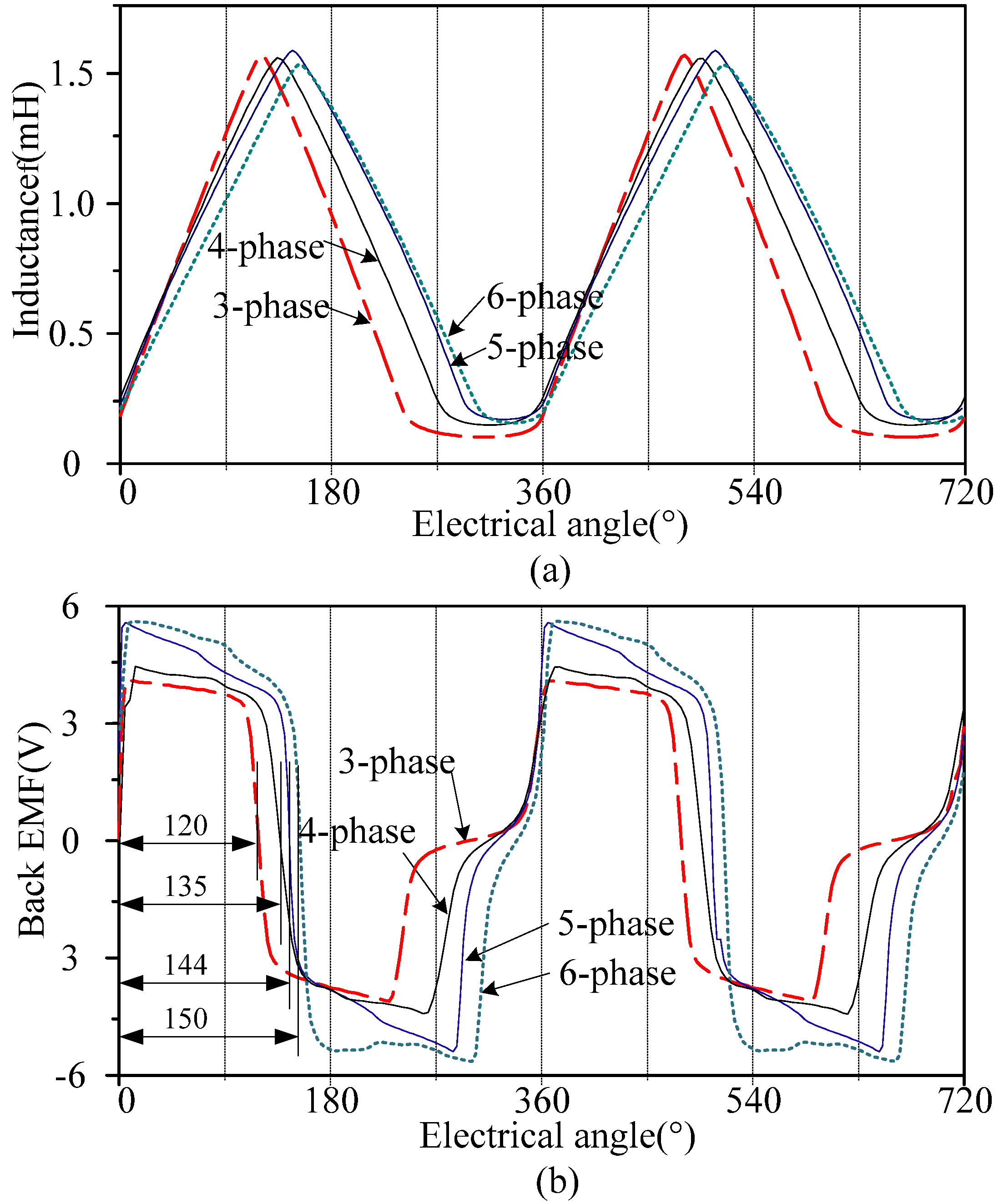
2.3. Simulation Results

Figure 4 shows Lpf and back EMF waveforms of the traditional multiphase WFDSMs, which are 12/8-pole three-phase, 8/6-pole four-phase 10/8-pole five-phase and 12/10-pole six-phase with the same stator pole arc coefficient αs = 0.5, and the rotor poles are as wide as the stator poles. The simulated result in Figure 4a shows that Lpf of the three-phase and four-phase WFDSM are consistent with the analysis result in Figure 2 and Figure 3. The back EMF waveforms in Figure 4b show that the electrical angles of the phase voltage waveforms of the four machines are approximately 120°, 135°, 144° and 150°. This verifies the calculation results in Equation (8).
With the total torque formula given in Equation (14), we can see that there is a torque component 1 2 i f 2 d L f which has nothing to do with the phase current ip. It can be called a cogging torque.
T = 1 2 i p 2 d L p + i p i f d L pf + 1 2 i f 2 d L f
where ip and if are the phase current and field current. In order to reduce the negative impact of the armature reaction, the number of turns of the field winding is much larger than the number of phase windings.
Figure 4. Lpf and up of multi-phase WFDSM. (a) Lpf; (b) The back EMF.
Energies 08 03640 g004
The self-inductance of the field winding Lf is much larger than the mutual inductance between the phase winding and field winding Lpf. Therefore, if Lf changes with the rotor position, and machine will generate a large cogging torque.
For the four-phase WFDSM with αs = 0.5, θ = 135°, and x = 3, there are three inductances changing at any time. This situation does not conform to Equation (13). With the self-inductance of the field winding Lf waveform in Figure 5a, we can see that Lf will change with the rotor position, which will produce cogging torque ripples. If αs = 0.667 and x = 4, the self-inductance of the field winding Lf will be a constant, as shown in Figure 5b. Therefore, if x is an odd number, the machine will not generate cogging torque.
Figure 5. Lf of the four-phase WFDSM. (a) αs = 0.5; (b) αs = 0.667.
Energies 08 03640 g005

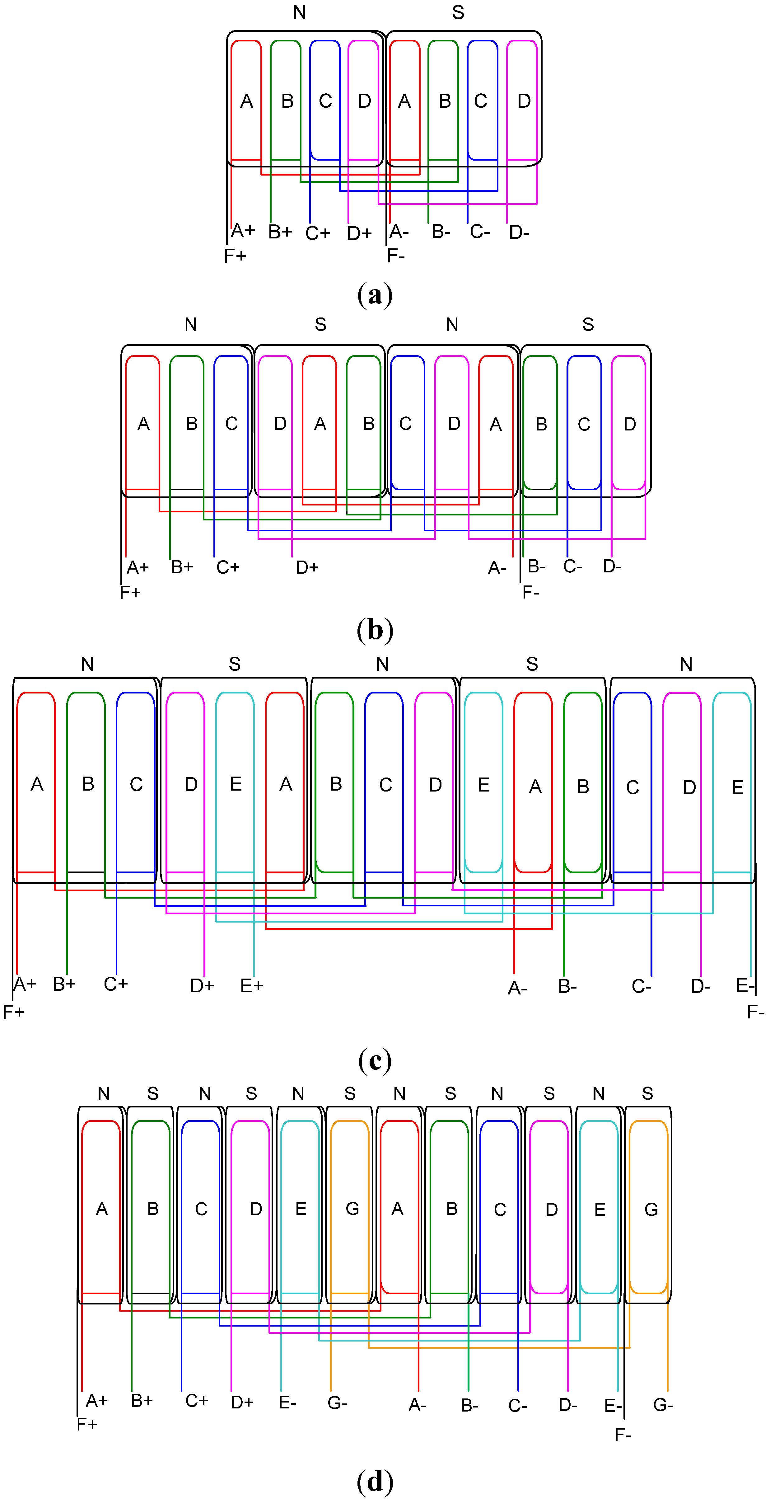
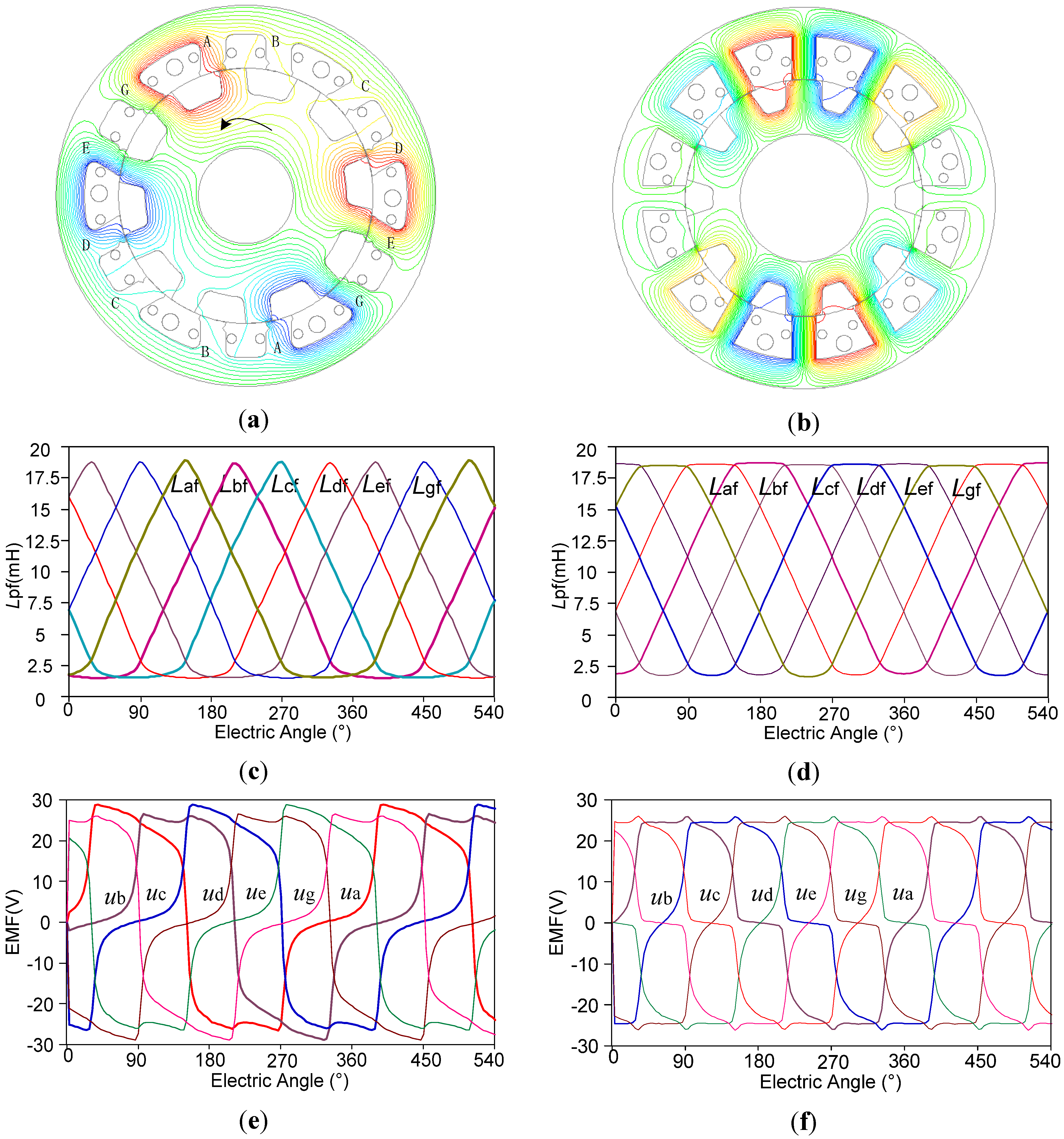
3. Comparative Study of the Symmetrical Phase Winding Configuration

3.1. The Symmetrical Phase Winding Configuration

As shown in Figure 1a, there are four field coils that are used to provide the magnetic field. Each field coil is wound around three stator poles. In Figure 1b, there are four stator poles in a field coil, which provides the magnetic field. Therefore, each excitation source of traditional m-phase doubly salient machine couples with m-phase coils. As the red lines show in Figure 1b, the magnetic circuit of phase A and D which are close to the excitation source is much shorter than phase B and C, and the inductance of phase A and D are larger than that of phase B and C. Overall the amplitudes of the inductance of the traditional four-phase WFDSM have the relationship given by Equation (15):
max ( L af ) = max ( L df ) > max ( L bf ) = max ( L cf )
If the phase coils with short flux road are divided averagely, the total inductances added by the series coils will be equal [12]. Let j stand for the number of phase coils that coupled by a field coil. The stator poles can be calculated with:
p s = m k = j P
where k and P are two natural numbers. Therefore, Ps is the least common multiple of m and j at least. Together with Equation (6), we can list the pole numbers of the four-phase WFDSM with different j in Table 2.
Table 2. The pole numbers of the four-phase WFDSM with different j.
jPoles of an element machine
Four-phaseFive-phaseSix-phase
j = 18/610/812/10
j = 28/610/812/10
j = 312/930/2412/10
j = 48/640/3224/20
j = 510/830/25
j = 612/10
When j = m, the machine is a traditional WFDSM with asymmetric phases. If j = 4 in the five-phase WFDSM and six-phase WFDSM, the number of stator pole will be very large since it increases with the least common multiple of j and m. And if j = 2, the field winding coils will increase, which in turn increases the copper consumption of the field winding. A three-phase 6/4-pole variable flux reluctance doubly salient machine was reported in [16], which verified that the WFDSM can operate well when j = 1. With the same configuration in [16], every stator pole of the multiphase WFDSM is wound with a field winding.
In the traditional 8/6-pole WFDSM, as shown in Figure 6a, each field coil is wound around four stator poles. All the coils of phase A and phase D are nearby the field coil slots, and the coils of the other two phases are in the middle of the two field coil slots. Therefore, the total reluctance of phase B is larger than the reluctance of phase A.
Figure 6. The connected coils of the multiphase WFDSM. (a) Traditional 8/6-pole four-phase; (b) new 12/9-pole four-phase; (c) 30/24-pole five-phase (half of the poles); (d) 12/10-pole six-phase.
Energies 08 03640 g006
The new 12/9-pole WFDSM has four field coils and twelve phase coils, which can be divided into four phases. As shown in Figure 6b, each field coil is wound around three stator poles, and the two neighboring field coils are in the opposite direction. Every phase has three coils, one is in the middle of the two field coil slots, and the other two phase coils are nearby the field coil slots. Therefore, the total reluctances of the four phases are equal. With the above analysis, the preferred configuration of the four-phase WFDSM with symmetry phases is with a 12/9-pole structure.
Similarly, we can draw the connected coils of the 30/24-pole five-phase WFDSM and the 12/10-pole six-phase WFDSM according to Table 2. Therefore, the elementary machine of the five-phase WFDSM with symmetry phases has a 30/24-pole structure.
In the six-phase WFDSM, if we wind the field coils around two or more stator poles, the six-phase WFDSM will still has the serious drawback of asymmetric phases, which will be verified by the simulation results in the next section Therefore, each stator pole of the 12/10-pole six-phase WFDSM should have a field coil if we want to get symmetrical phases.

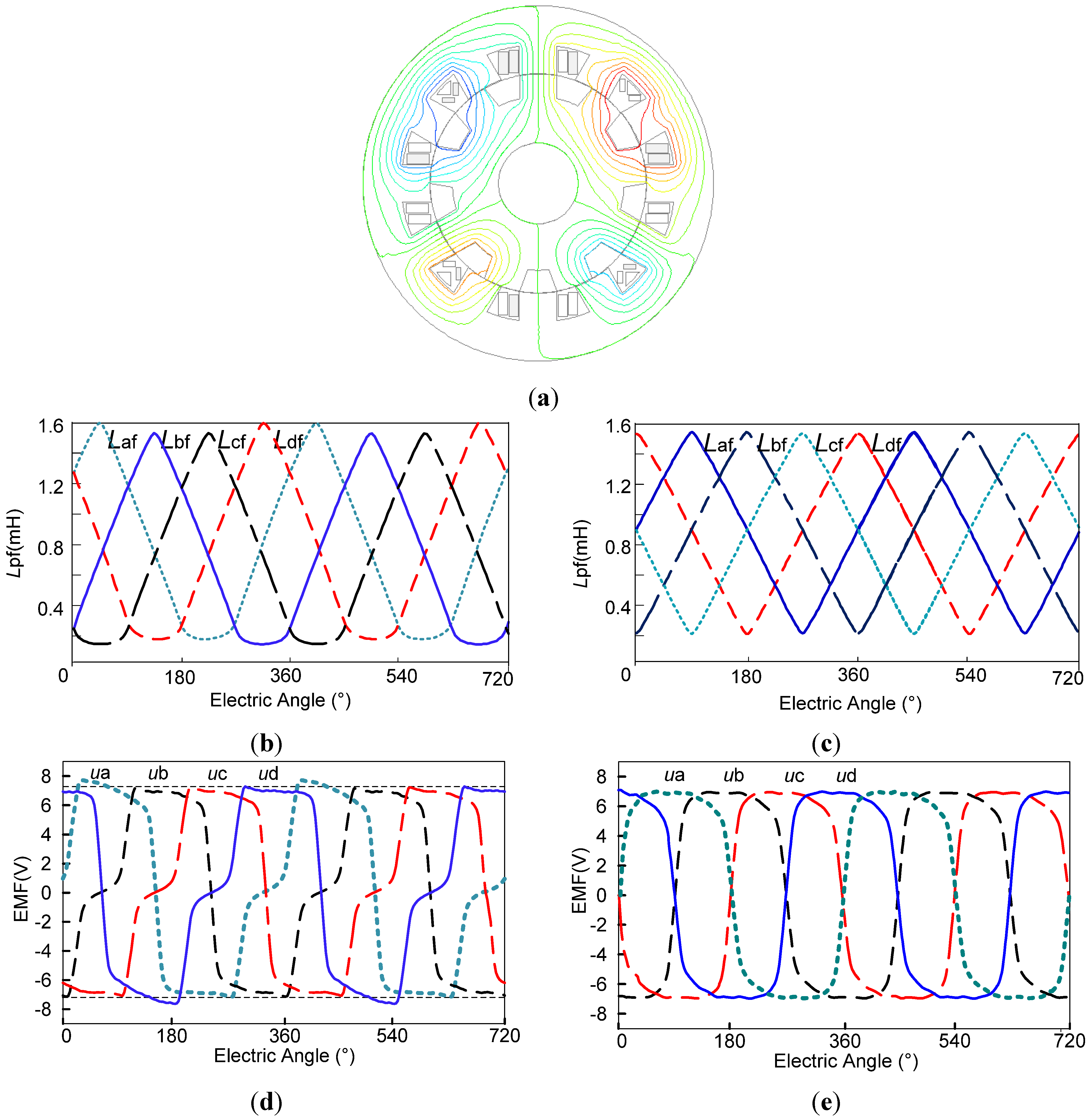
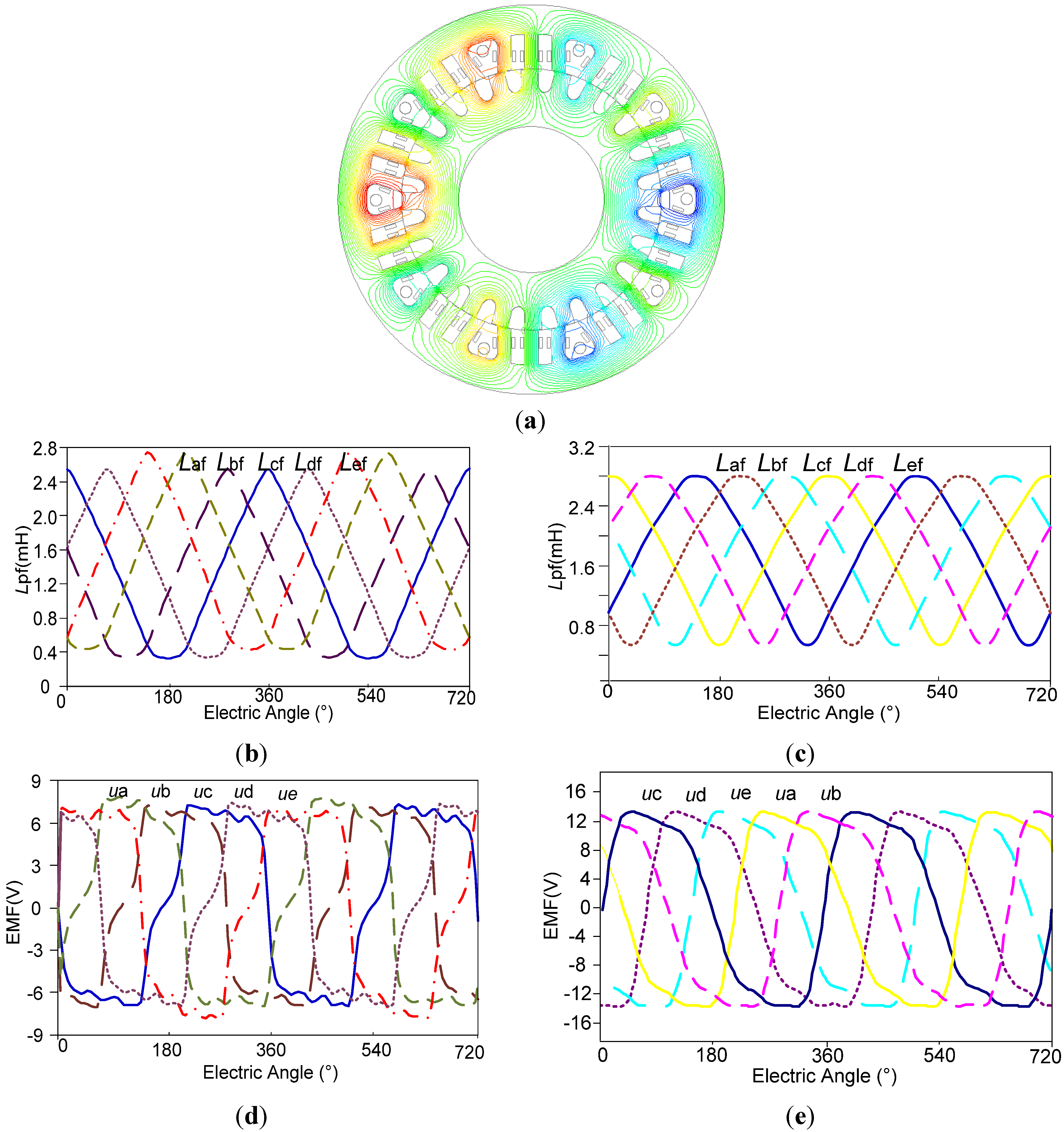
3.2. Simulation Results

To compare the above multiphase WFDSMs, the simulation models of the traditional 8/6-pole and new 12/9-pole four-phase WFDSM were established. Figure 7a shows the flux of the 12/9-pole machine. Figure 7b shows the inductance between phase winding and field winding of the traditional 8/6-pole four-phase WFDSM. This verifies the formula of Equation (17). Figure 7c shows the same inductance of the new 12/9-pole four-phase WFDSG. It is shown that the amplitudes of the inductances have the relationship with:
max ( L af ) = max ( L df ) = max ( L bf ) = max ( L cf )
The 2D-FEA results agree well with the theoretical analysis results. Figure 7d,e show the waveforms of the back EMF of the four-phase WFDSMs. The back EMFs of the traditional 8/6-pole WFDSM have slight difference in the amplitude and the shape of the waveform.
As the preferred five-phase WFDSM has a 30/24-pole structure, j = 3; its flux distribution is shown in Figure 8a. Figure 8b shows the inductances between the phase windings and the field winding of the traditional 10/8-pole five-phase WFDSM. The same inductance of the new 30/24-pole four-phase WFDSG is shown in Figure 8c. It shows that the traditional five-phase WFDSG has the disadvantage of asymmetric phases. The new WFDSG with its field coils wound around three poles can solve this problem. The theoretical analysis results are verified with these 2D-FEA results.
Figure 8d,e show the waveforms of the back EMF of the five-phase WFDSMs. It can be calculated that the back EMFs of different phases of the traditional 10/8-pole WFDSM have a difference of about 10.9%.
From the above analysis, we know that the traditional six-phase WFDSM with j = 6 has the phase asymmetry problem because the field coils is wound around six stator poles. We have set up the simulation models of the six-phase WFDSMs with different j. But even if we let j = 5, 4 or 3, there will be phase asymmetry problem.
If j = 2, the 12/10-pole six-phase WFDSM has a field coil wound around every two stator poles, and it also has the problem of asymmetric phases. As shown in Figure 9a, when the rotor pole is sliding to the pole of phase B, the back EMF of the phase B will be less than phase A because the pole of phase A has a lot of flux at this time. When the rotor pole is sliding to the pole of phase A, the back EMF of the phase A will be larger than phase B because the pole of phase B has no flux at this time. This is verified by the Figure 9d, which shows that the amplitudes of ua and ub are not equal. Therefore, the phases are still asymmetric even with j = 2.
Figure 7. Comparison of the traditional and the new four-phase WFDSM. (a) The flux of the 12/9-pole WFDSM; (b) Lpf of the traditional 8/6-pole WFDSM; (c) Lpf of the new 12/9-pole WFDSM; (d) Back EMF of the 8/6-pole WFDSM; (e) Back EMF of the 12/9-pole WFDSM.
Energies 08 03640 g007
Figure 8. Comparison of the traditional and the new five-phase WFDSM. (a) The flux of the 30/24-pole WFDSM; (b) Lpf of the traditional 10/8-pole WFDSM; (c) Lpf of the new 30/24-pole WFDSM; (d) Back EMF of the 10/8-pole WFDSM; (e) Back EMF of the 30/24-pole WFDSM.
Energies 08 03640 g008
The flux of the six-phase WFDSM with j = 1 is shown in Figure 9b. This new WFDSG has its field coils wound around every stator pole, and solves the problem of phase asymmetry. The 2D-FEA results in Figure 9f verified this theoretical analysis. However, this new machine has a drawback of large copper loss, because there are field coils in every slot, and the resistance and the weight of the field winding will be increased.
Figure 9. Comparison of the new 12/10-pole six-phase WFDSM. (a) The flux of the WFDSM with j = 2; (b) The flux of the WFDSM with j = 2. (c) Lpf of the WFDSM with j = 2; (d) Lpf of the WFDSM with j = 1; (e) Back EMF of the WFDSM with j = 2; (f) Back EMF of the WFDSM with j = 1.
Energies 08 03640 g009

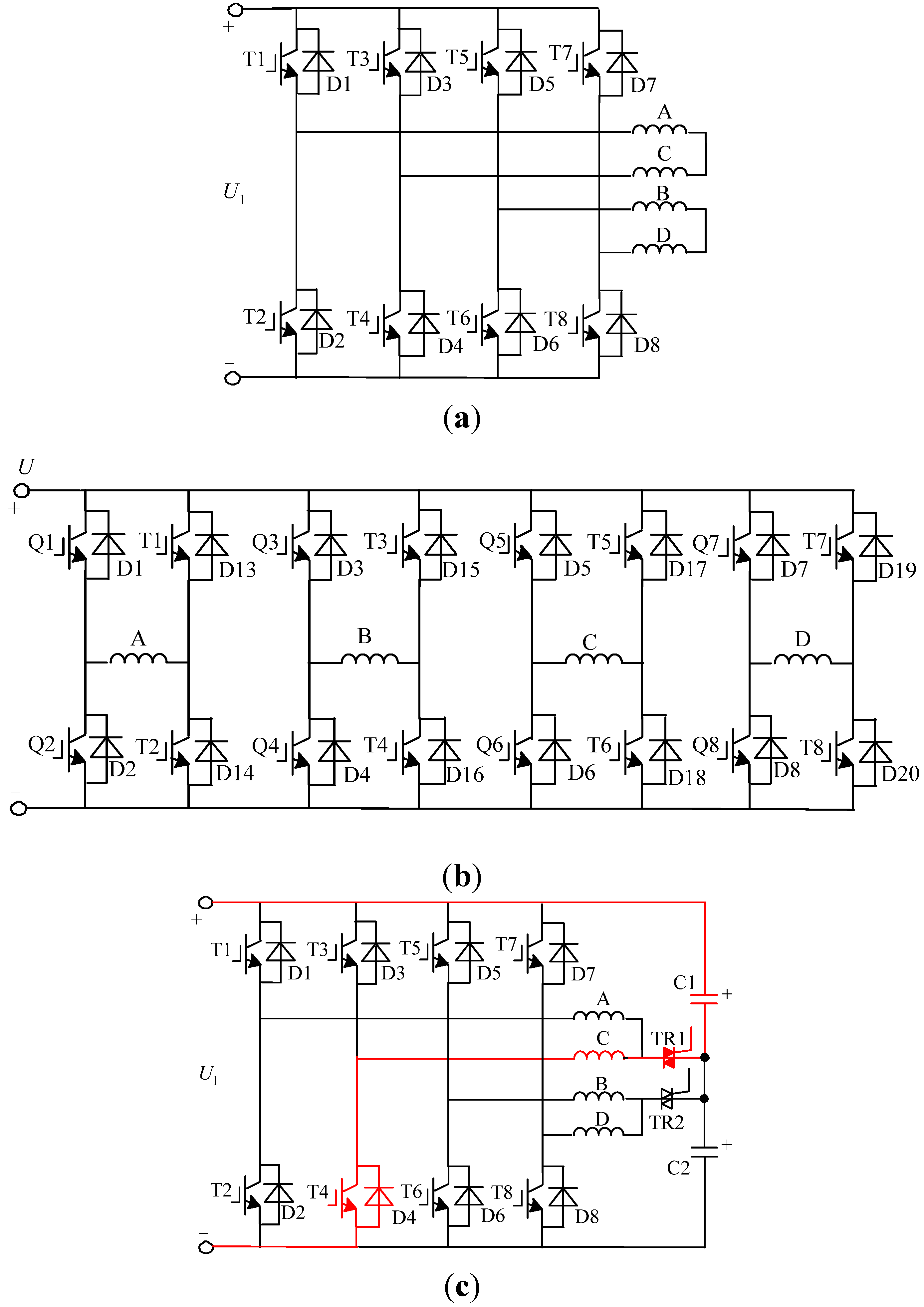
4. Comparative Study of the Converter and Its Fault-Tolerant Performance

4.1. The Fault-Tolerant Converters

Multiphase machines can be divided into machines with prime number phases and machines with composite number phases. Because a composite number has at least one positive divisor other than 1 or the number itself, the machines with composite number phases can be divided into several channels which have little effect on each other [24]. For example, the four-phase WFDSM can be divided into two independent channels. However, the five-phase WFDSM has no positive divisor, and the machine may be susceptible to be suffer faults if the phase windings are connected together.
The fault-tolerant machine is usually equipped with a fault-tolerant converter. There are various types of fault-tolerant converters for different phase machines [25], and the four-phase converters will be discussed as an example in this paper.
The four-phase WFDSM is usually powered with a four-phase full bridge converter [26]. When there is a fault in one phase, the machine can keep on working because the fault is isolated from the other two phases, as shown in Figure 10a.
Figure 10. Comparison of the four-phase fault-tolerant converter. (a) The traditional four-phase converter; (b) The four-phase H bridges converter; (c) The half bridge four-phase converter.
Energies 08 03640 g010
The most excellent converter is the four-phase H bridges converter, as shown in Figure 10b, because all of the phases are isolated from each other. The machine can be designed as a modular machine, which offers potential fault-tolerant capability because the phase windings are isolated. When there is a fault in one phase, the other phases can keep on working without any infection from the fault phase. However, this converter design is not helpful to reduce the weight and the cost.
Figure 10c shows a half bridge four-phase converter. If phase A has an open circuit fault in this fault-tolerant converter, phase C of the machine can keep on operating with the help of split-phase capacitor C1. However, the five-phase WFDSM cannot be divided into two or three isolated channels, so it doesn’t have such flexible fault-tolerant converters, and the faults of the machine may be susceptible to be infected if the phase windings are connected together.
As we can see from Figure 10, the switches increase with the phase number, and WFDSMs with more than six phases are not suitable because the weight and the cost are unacceptable. The WFDSMs with six phases or four phases can be divided into two isolated channels, which will improve the fault tolerance of the machine.

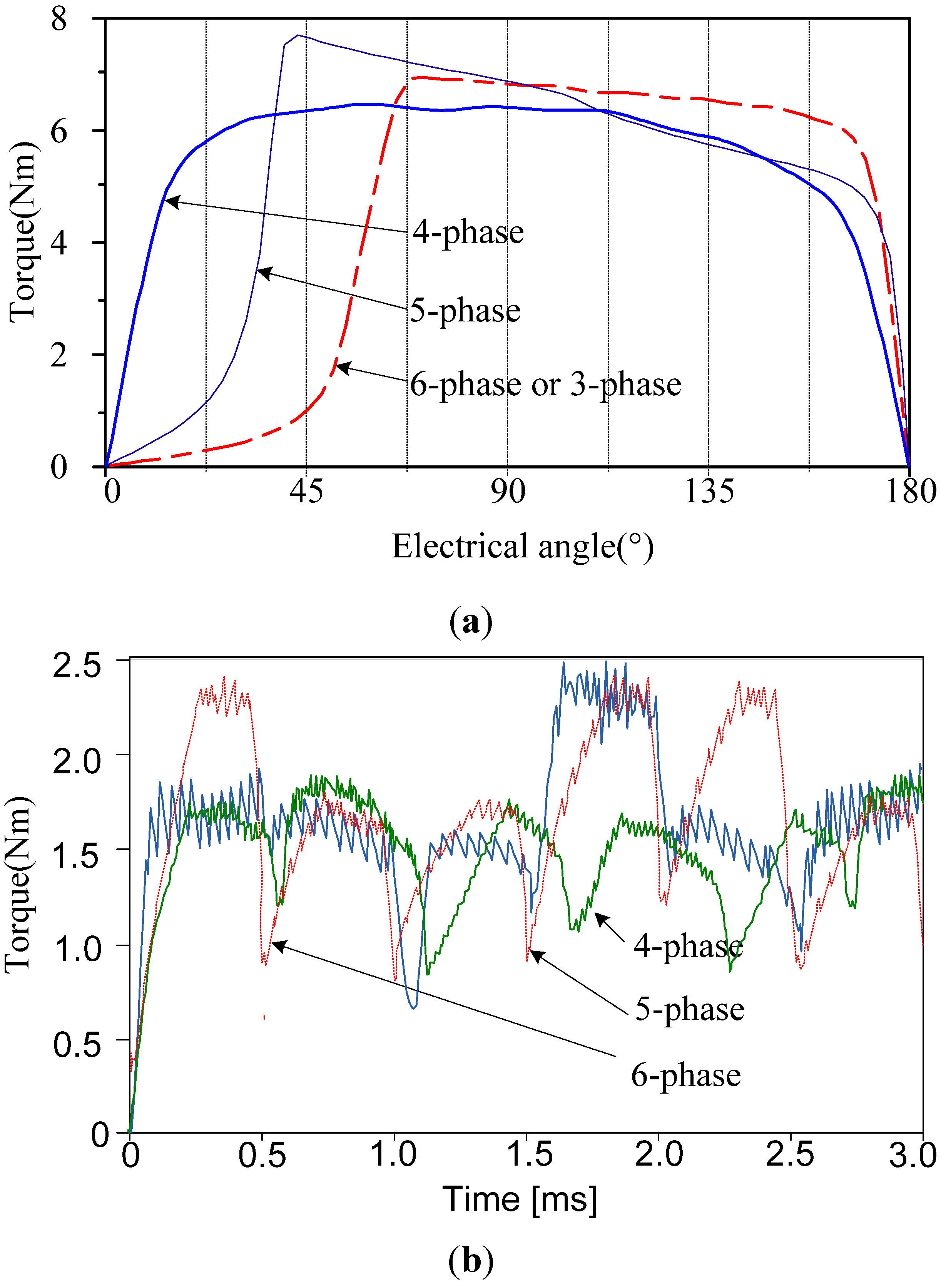
4.2. Fault-Tolerant Performance Comparison

The torque-angle characteristics of the multiphase WFDSMs are shown in Figure 11a. As we can see from the figure that the waveform of the 12/9-pole four-phase WFDSM is wider than the others, because the electrical angle of the phase voltage waveform of the four-phase WFDSM in Equation (8) is 180° and the phase voltage waveform electrical angle of the five-phase WFDSM is 144°, and the angle of the six-phase WFDSM is 120°.
There are four phases with mutative self-inductances at any time in all of the three WFDSMs, which can be described as x = 4 in Equation (8). If one phase of the four-phase WFDSM is isolated because of an open circuit or short circuit fault, the other three phases can keep on working. If the phase current maintains the same value because there is no fault, the fault-tolerant torque will be three-quarters of the normal torque. This is verified with Figure 11b.
To compare the fault-tolerant performance, the torque waveform with one phase open of the five-phase and the six-phase WFDSMs are shown in Figure 11b too. If the five steps in one period are named as five beats, then in the five beats of the five-phase WFDSM, there is a beat where the fault phase has no current. At this time, the output torque is equal to the normal torque. In the other beats, the fault-tolerant torque will be three-quarters of the normal torque too. The same result can be obtained with the six-phase WFDSM. This phenomenon is shown in Figure 11b. Because the WFDSMs are brushless DC machines, and their torque ripples are relatively large, which is mainly caused by the commutation torque ripple in the four-phase WFDSM. It should be noted that the commutation torque ripple of the WFDSM can be reduced by the optimal control method, which is investigated in [27]. Besides the commutation torque ripples, the five-phase and the six-phase WFDSMs also have the torque ripples caused by the differences between fault-tolerant beats and normal beats.
Figure 11. The torque of the multiphase WFDSMs. (a) The torque-angle characteristics; (b) The torque with one phase isolated in an H bridge converter.
Energies 08 03640 g011
What’s more, as a brushless DC machine, the WFDSM is usually equipped with Hall sensors. Therefore, the five-phase WFDSM needs five Hall sensors, and the six-phase WFDSM needs only three Hall sensors, because phase A and phase D of the six-phase WFDSM have adverse EMF. The accuracy of the sensor should increase with the rotor pole number. Because the rotor pole number of the five-phase WFDSM with symmetrical phases is larger than the others, therefore, it is not an optimal solution for a fault-tolerant machine.

5. Conclusions

The four-phase WFDSM with αs = 0.667 has four changing inductance phases at any time, and its self-inductance of the field winding Lf will be a constant, which will not produce cogging torque. If it is used as a fault-tolerant machine, it has fewer switches in the converters than five-phase or six-phase machines.
The elementary machine of the five-phase WFDSM with symmetric phases has a 30/24-pole structure. It does not have cogging torque because the phase number with mutative inductance at any time is four. Different from the other five-phase machines with few poles, this five-phase WFDSM needs an expensive incremental encoder to provide sufficient position accuracy for the commutation control, but it can be a high performance fault-tolerant generator because it doesn’t need position sensors.
If we wind the field coils around two or more stator poles, the six-phase WFDSM will have the serious drawback of asymmetric phases. The 12/10-pole six-phase WFDSM which has a field coil around each stator pole has symmetric phases, although it improves the copper loss of the field windings. Like the four-phase WFDSM, the six-phase WFDSM can be divided into two isolated channels, which will improve the fault tolerance of the machine. Because the switches of the converter and the pole numbers increase with the phase number, WFDSMs with more than six phases are not suitable because the weight and the cost of the converter are unacceptable, as well as the pole numbers.

Acknowledgments

This work was supported and funded by the National Natural Science Foundation of China (51477075), the Shandong Provincial Natural Science Foundation (ZR2014JL035), and the Fundamental Research Funds for the Central Universities (NP2015205).

Author Contributions

Bo Zhou conceived the idea of this paper, provide guidance and supervision; Li-Wei Shi implemented the research, performed the analysis and wrote the paper. All authors have contributed significantly to this work.

Conflicts of Interest

The authors declare no conflict of interest.

References

  1. Villani, M.; Tursini, M.; Fabri, G.; Castellini, L. Electromechanical actuator for helicopter rotor damper application. IEEE Trans. Ind. Appl. 2014, 2, 1007–1014. [Google Scholar] [CrossRef]
  2. Boglietti, A.; Cavagnino, A.; Tenconi, A.; Vaschetto, S. The safety critical electric machines and drives in the more electric aircraft: A survey. In Proceedings of the 35th Annual Conference of IEEE Industrial Electronics, Porto, Portugal, 3–5 November 2009; pp. 2987–2995.
  3. Bennett, J.W.; Atkinson, G.J.; Mecrow, B.C.; Atkinson, D.J. Fault-tolerant design considerations and control strategies for aerospace drives. IEEE Trans. Ind. Electron. 2012, 5, 2049–2058. [Google Scholar] [CrossRef]
  4. Garcia, A.; Cusido, J.; Rosero, J.A.; Ortega, J.A.; Romeral, L. Reliable electro-mechanical actuators in aircraft. IEEE Aerosp. Electron. Syst. Mag. 2008, 8, 19–25. [Google Scholar] [CrossRef]
  5. Villani, M.; Tursini, M.; Fabri, G.; Castellini, L. High reliability permanent magnet brushless motor drive for aircraft application. IEEE Trans. Ind. Electron. 2012, 5, 2703–2711. [Google Scholar]
  6. Hao, L.; Du, H.Y.I.; Lin, H.; Namuduri, C. Design and analysis of PM fractional slot machine considering the fault operation. IEEE Trans. Ind. Appl. 2014, 1, 234–243. [Google Scholar]
  7. Stewart, P.; Kadirkamanathan, V. Commutation of permanent-magnet synchronous AC motors for military and traction applications. IEEE Trans. Ind. Electron. 2003, 3, 629–630. [Google Scholar] [CrossRef]
  8. Du, Q.; Lu, E.; Shi, X. Design and analysis of five-phase tangent magnetic field permanent magnet generator for electric vehicle. Int. J. Electric Hybrid Veh. 2012, 4, 378–389. [Google Scholar] [CrossRef]
  9. Rottach, M.; Gerada, C.; Wheeler, P.W. Design optimisation of a fault-tolerant pm motor drive for an aerospace actuation application. In Proceedings of the 7th IET International Conference on Power Electronics, Machines and Drives, Manchester, UK, 8–10 April 2014; pp. 1–6.
  10. Cossar, C.; Kelly, L.; Miller, T.J.E.; Whitley, C.; Maxwell, C.; Moorhouse, D. The design of a switched reluctance drive for aircraft flight control surface actuation. IEE Colloq. Electr. Mach. Syst. More Electric Aircr. 1999, 11, 1–8. [Google Scholar]
  11. Hennen, M.D.; Hennen, M.D.; Heyers, C.; Brauer, H.J.; De Doncker, R.W. Development and control of an integrated and distributed inverter for a fault tolerant five-phase switched reluctance traction drive. IEEE Trans. Ind. Electron. 2012, 2, 547–554. [Google Scholar]
  12. Gong, Y.; Chau, K.T.; Jiang, J.Z.; Yu, C.; Li, W. Design of doubly salient permanent magnet motors with minimum torque ripple. IEEE Trans. Magn. 2009, 10, 4704–4707. [Google Scholar] [CrossRef] [Green Version]
  13. Zhang, Z.; Yan, Y.; Tao, Y. A new topology of low speed doubly salient brushless DC generator for wind power generation. IEEE Trans. Magn. 2012, 3, 1227–1233. [Google Scholar] [CrossRef]
  14. Chen, Z.; Wang, H.; Yan, Y. A doubly salient starter-generator with two-section twisted-rotor structure for potential future aerospace application. IEEE Trans. Ind. Electron. 2012, 9, 3588–3595. [Google Scholar] [CrossRef]
  15. Liu, C.; Chau, K.T.; Zhong, J.; Li, J. Design and analysis of a HTS brushless doubly-fed doubly-salient machine. IEEE Trans. Appl. Supercond. 2011, 3, 1119–1122. [Google Scholar] [CrossRef] [Green Version]
  16. Liu, X.; Zhu, Z.Q. Electromagnetic performance of novel variable flux reluctance machines with DC-field coil in stator. IEEE Trans. Magn. 2013, 6, 3020–3028. [Google Scholar] [CrossRef]
  17. Yu, L.; Zhang, Z.; Chen, Z.H. Analysis and verification of the doubly salient brushless DC generator for automobile auxiliary power unit application. IEEE Trans. Ind. Electron. 2014, 12, 6655–6663. [Google Scholar] [CrossRef]
  18. Sui, Y.; Zheng, P.; Wu, F.; Yu, B.; Wang, P.F.; Zhang, J.W. Research on a 20-Slot/22-Pole five-phase fault-tolerant PMSM used for four-wheel-drive electric vehicles. Energies 2014, 7, 1265–1287. [Google Scholar] [CrossRef]
  19. Cheng, M.; Hua, W.; Zhang, J.; Zhao, W. Overview of stator-permanent magnet brushless machines. IEEE Trans. Ind. Electron. 2011, 11, 5087–5101. [Google Scholar] [CrossRef]
  20. Zhao, Y.; Wang, H.; Zhao, X.; Xiao, L. Characteristics analysis of five-phase fault-tolerant doubly salient electro-magnetic generators. In Proceedings of the IECON 2013—The 39th Annual Conference of the IEEE, Vienna, Austria, 10–13 November 2013; pp. 2668–2673.
  21. Liu, X.; Zhu, Z.Q. Stator/Rotor pole combinations and winding configurations of variable flux reluctance machines. IEEE Trans. Ind. Appl. 2014, 6, 3675–3684. [Google Scholar] [CrossRef]
  22. Shi, J.T.; Liu, X.; Wu, D.; Zhu, Z.Q. Influence of stator and rotor pole arcs on electromagnetic torque of variable flux reluctance machines. IEEE Trans. Magn. 2014, 11. [Google Scholar] [CrossRef]
  23. Gaussens, B.; Hoang, E.; Barrière, O.D.; Saint-Michel, J.; Lecrivain, M.; Gabsi, M. Analytical approach for air-gap modeling of field-excited flux-switching machine: No-load operation. IEEE Trans. Magn. 2012, 9, 2505–2517. [Google Scholar] [CrossRef]
  24. Hill, C.I.; Zanchetta, P.; Bozhko, S.V. Accelerated electromechanical modeling of a distributed internal combustion engine generator unit. Energies 2012, 5, 2232–2247. [Google Scholar] [CrossRef]
  25. Bojoi, R.; Neacsu, M.G.; Tenconi, A. Analysis and survey of multi-phase power electronic converter topologies for the more electric aircraft applications. In Proceedings of the 2012 International Symposium on Power Electronics, Electrical Drives, Automation and Motion (SPEEDAM), Sorrento, Italy, 20–22 June 2012; pp. 440–445.
  26. Chen, Z.; Chen, R.; Chen, Z. A fault-tolerant parallel structure of single-phase full-bridge rectifiers for a wound-field doubly salient generator. IEEE Trans. Ind. Electron. 2013, 8, 2988–2995. [Google Scholar] [CrossRef]
  27. Qin, H.; Wen, J.; Zhou, B.; Xue, H.H. Considerations of harmonic and torque ripple in a large power doubly salient electro-magnet motor drive. In Proceedings of the 2012 Asia-Pacific Symposium on Electromagnetic Compatibility (APEMC), Singapore, 22–24 May 2012; pp. 649–652.

