Article

Mechanism Analysis and Experimental Validation of Employing Superconducting Magnetic Energy Storage to Enhance Power System Stability

State Key Laboratory of Advanced Electromagnetic Engineering and Technology, Huazhong University of Science and Technology, Wuhan 430074, China
*
Author to whom correspondence should be addressed.
Energies 2015, 8(1), 656-681; https://doi.org/10.3390/en8010656
Submission received: 18 November 2014 / Revised: 22 December 2014 / Accepted: 12 January 2015 / Published: 20 January 2015

Abstract

:
This paper investigates the mechanism analysis and the experimental validation of employing superconducting magnetic energy storage (SMES) to enhance power system stability. The models of the SMES device and the single-machine infinite-bus (SMIB) system with SMES are deduced. Based on the model of the SMIB system with SMES, the action mechanism of SMES on a generator is analyzed. The analysis takes the impact of SMES location and the system operating point into consideration, as well. Based on the mechanism analysis, the P-controller and Q-controller are designed utilizing the phase compensation method to improve the damping of the SMIB system. The influence of factors, such as SMES location, transmission system reactance, the dynamic characteristics of SMES and the system operating point, on the damping improvement of SMES, is investigated through root locus analysis. The simulation results of the SMIB test system verify the analysis conclusions and controller design method. The laboratory results of the 150-kJ/100-kW high-temperature SMES (HT-SMES) device validate that the SMES device can effectively enhance the damping, as well as the transient stability of the power system.

1. Introduction

The interconnection of regional power systems and the integration of renewable energy generation make the stability of a large-scale power system increasingly important and challenging [1]. To enhance power system stability, various types of controllers are employed for power systems, such as power system stabilizers (PSSs) and supplementary damping controllers of the flexible AC transmission system (FACTS) devices. As superconducting magnetic energy storage (SMES) is capable of commutating both active and reactive power with the grid rapidly and independently, it has better performance than FACTS in terms of damping improvement [2,3,4]. In 1981, the first SMES application in a power system was successfully tested by the Bonneville Power Administration (BPA) [5]. In recent years, experimental projects with new types of SMES devices for power quality and stability enhancement have been developed in East Asia [6,7,8,9].
In order to analyze the efficacy of SMES in power systems, various SMES model methods are utilized to analyze the power system with SMES. The SMES device has been modeled as a variable impedance [10] or variable current source [11]. The work in [12] represents the SMES by the phase and magnitude variation of the voltage of the bus where the SMES device is installed. Most of these references consider SMES indirectly and use the equivalent effect of SMES instead of it alone. As SMES usually directly commutates active and reactive power with the grid, there will be a need for transformation between the commutating power and the equivalent variables, and the dynamics of the transformation are usually ignored. On the other hand, various control techniques are utilized to design the SMES controllers, which generate orders for the power conditioning system (PCS) of the SMES device. The conventional proportional (P) controller and proportional-integral (PI) controller are adopted for the SMES device in several experimental projects described in [8,13]. These references mainly focus on the experimental results and give few details about the controller design. Many advanced control techniques are also utilized to design controllers for SMES, such as the linear robust control method [14], the nonlinear robust control method [15], the extended backstepping method [16], and so on. Most of them design the SMES controllers from the viewpoint of control theory and pay little attention to the action mechanism of SMES. Besides, the impact of SMES location and the system operating point on SMES performance is investigated through experiments [13]; however, a detailed explanation is not given, and the characteristics of SMES are not taken into consideration.
This paper deduces the model, which takes active and reactive power as inputs, of the single-machine infinite-bus (SMIB) system with SMES. Based on the obtained model, the action mechanism of SMES is analyzed. The analysis takes the impact of different locations of SMES and the variation of the system operating conditions into account. The P-controller and Q-controller for SMES used to improve the system damping are designed using the phase compensation method. The influence of factors, such as SMES location, transmission system reactance, the dynamic characteristics of SMES and the system operating point, on the damping improvement of SMES is evaluated through root locus analysis. Both simulation and the laboratory experiment results verify the analysis conclusions and the effectiveness of employing SMES to enhance power system stability.
The rest of the paper is organized as follows. Section 2 briefly introduces the topology of SMES and the model of the SMIB system with SMES. Section 3 analyzes the action mechanism of SMES. Section 4 designs SMES controllers to increase system damping using the phase compensation method and evaluates the influence of different factors on the performance of SMES. Section 5 and Section 6 present the simulation and experimental results, respectively. Conclusions are drawn in Section 7.

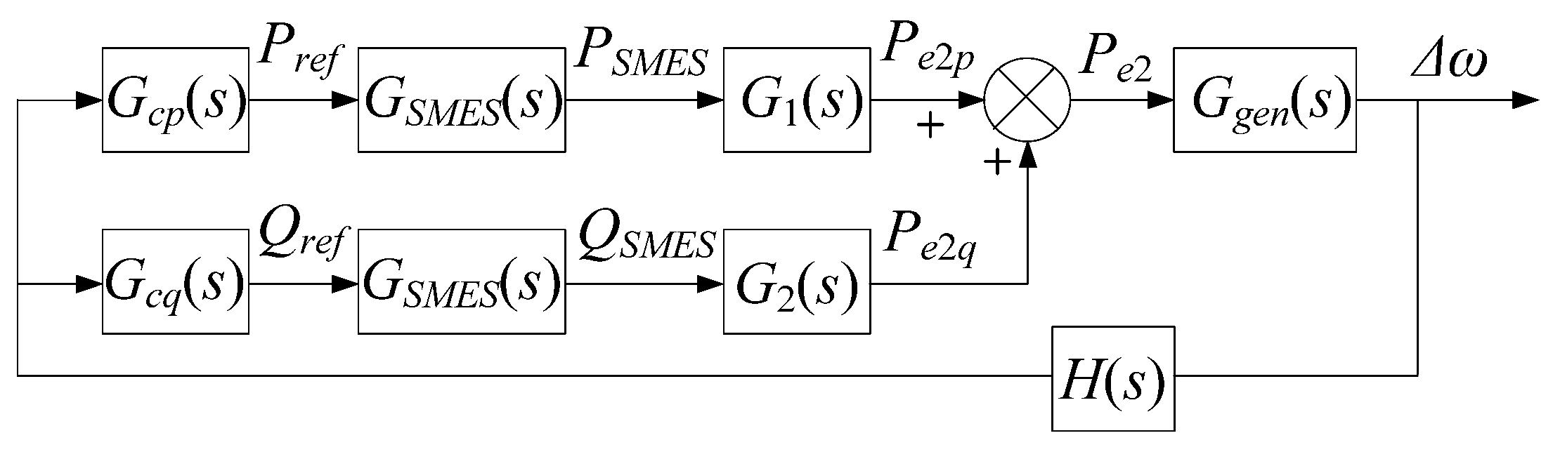
2. Model of SMES and SMIB System with SMES

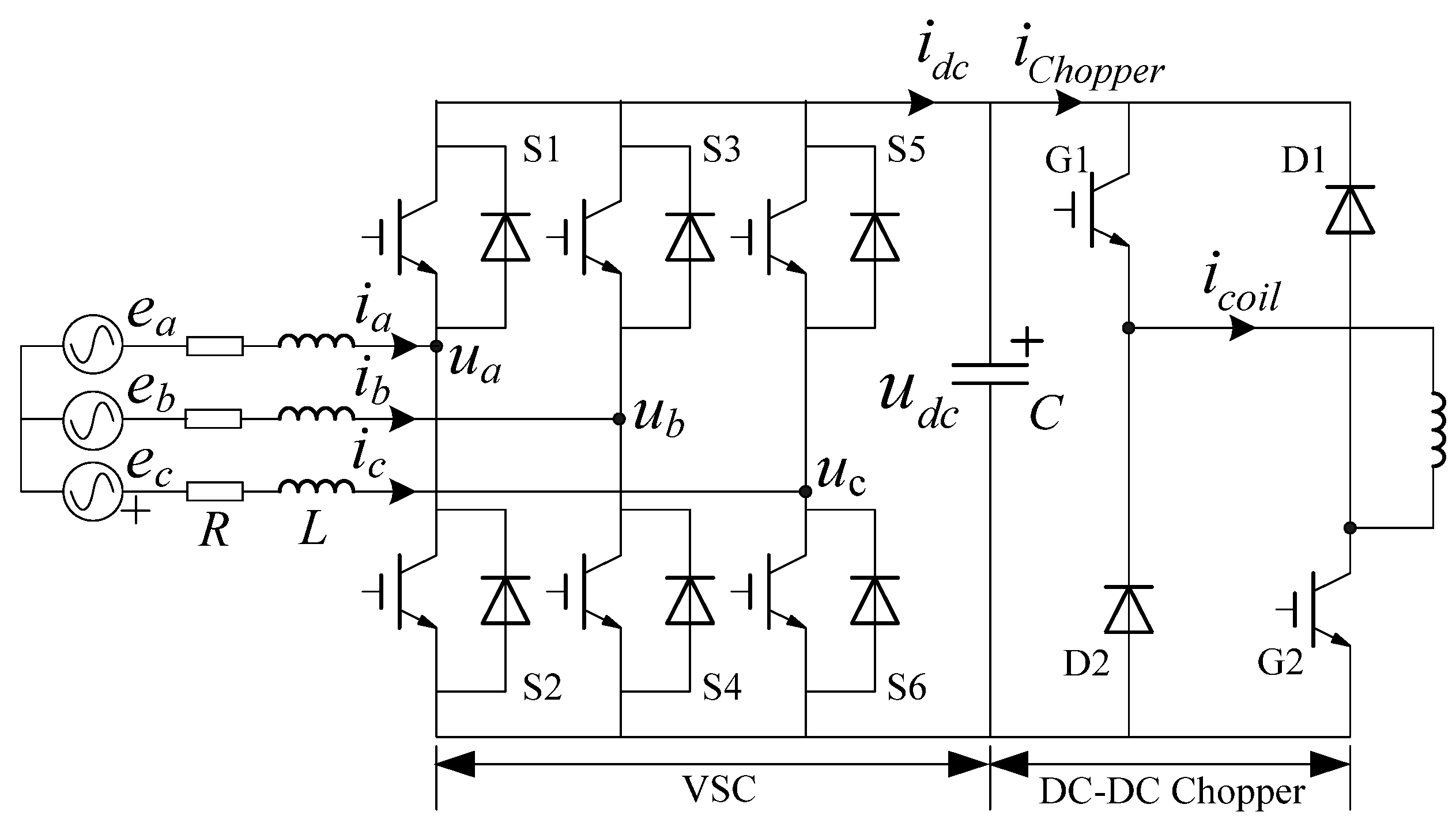
2.1. Topology and Model of SMES

A SMES device mainly consists of two parts: a PCS used for power commutation control and a superconductive magnet used for energy storage. According to the topology configuration [3], the PCS can be classified into three categories: thyristor-based PCS, voltage source converter (VSC)-based PCS and current source converter (CSC)-based PCS. The last two kinds of PCSs can track active and reactive power reference quickly and independently [17] and have almost the same external dynamic characteristics. Without loss of generality, the two-level VSC-based PCS is used for investigation in this paper. Note that the conclusions drawn from this paper are also applicable to the other categories.
Figure 1 shows the topology of the main circuit of SMES with a two-level VSC-based PCS. The PCS can be further divided into two parts: the VSC and the DC–DC chopper. From Figure 1, the state equations of VSC in the dq rotating coordinate system can be derived as follows [18]:
d d t i d = R L i d + ω i q + e d M d u dc L d d t i q = R L i q ω i d + e q M q u dc L d d t Q C = 3 2 ( i d e d + i q e q ) P SMES
Figure 1. Topology of the main circuit of superconducting magnetic energy storage (SMES) with a two-level voltage source converter (VSC)-based power conditioning system (PCS).
Energies 08 00656 g001
If the bang-bang control mode is adopted by the chopper controller [3], the DC–DC chopper can be modeled as follows:
P coil = u dc ( 2 D 1 ) i coil
Ignoring the resistance, the magnet can be modeled as an inductance, whose state equation is:
d d t Q L = P coil
It can be found from Equation (1) that id and iq can be controlled by Md and Mq, and QC can be controlled by Pcoil, which is converted into D used in the chopper controller through Equation (2). Meanwhile, the energy in the magnet will change according to Equation (3). When SMES is used to improve the system damping or to enhance the transient stability, the VSC usually tracks the power references from the SMES controllers, and at the same time, the chopper maintains the DC voltage. As a result, the chopper decouples the VSC from the magnet, making the dynamics of VSC have little to do with the magnet, as long as the energy stored in the magnet is capable of maintaining the DC voltage. Therefore, the model of VSC can be used to represent the entire SMES device in the analysis of the power system with SMES.
Figure 2 depicts the control diagram of the two-level VSC-based PCS. It is composed of the chopper controller and the VSC controller. The chopper controller maintains the DC voltage or the current of the magnet by regulating the power of the magnet. The different control objective is switched by the mode switch in the chopper controller.
Figure 2. Control diagram of the PCS. (a) Diagram of chopper controller; (b) diagram of VSC controller. PI: proportional-integral; PMM, Pulse-width Modulation.
Energies 08 00656 g002
A double closed-loop structure is usually utilized by the VSC controller. It uses feed-forward compensation to decouple active and reactive current and, thus, regulates them independently. When the PI parameters are tuned according to the second-order optimal principle [19], the transfer functions from the reference current to the actual value are:
I k ( s ) I k ref ( s ) = 1 4 ξ i 2 T Σ i 2 s 2 + 4 ξ i 2 T Σ i s + 1 ( k = d , q )
The current references of the inner loop are generated by the outer power loop, as illustrated in Figure 2b. When taking the actual measurement into consideration, the transfer function of active power can be found as Equation (5), and the reactive power has the same transfer function. These transfer functions describe the dynamics of VSC and can be used as the model of the entire SMES device.
P ( s ) P ref ( s ) = 1 ( 1 + T Σ p ) ( 4 ξ i 2 T Σ i 2 s 2 + 4 ξ i 2 T Σ i s + 1 )

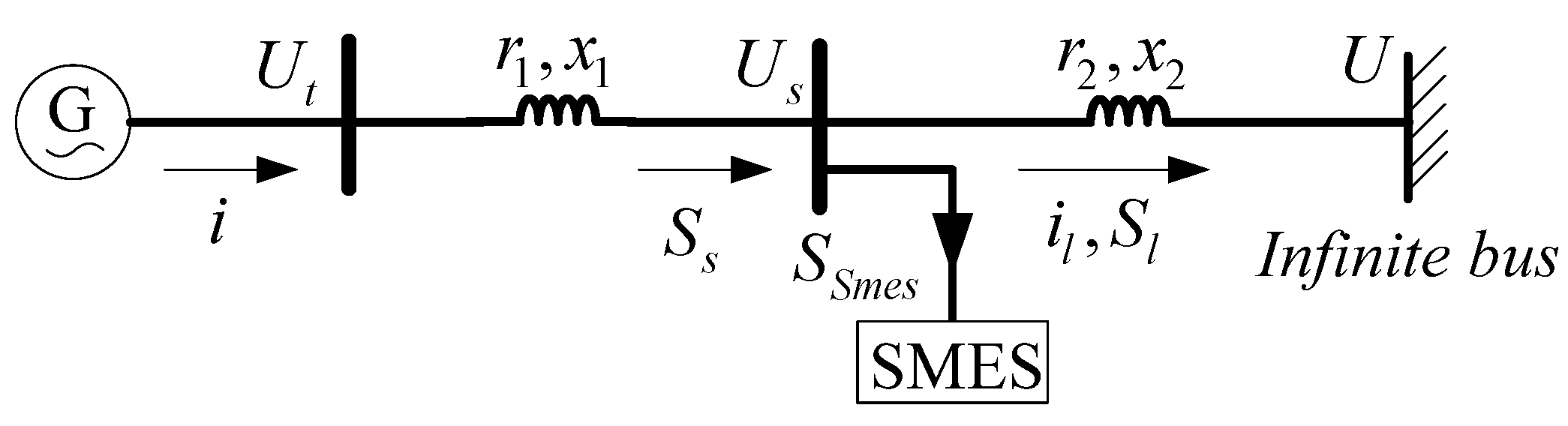
2.2. Small Signal Model of the SMIB System with SMES

The diagram of the SMIB system with SMES is depicted in Figure 3. The location factor α of the SMES device is defined as α = x1/xΣ, where xΣ = x1 + x2. Note that α equals zero when SMES is installed at the generator terminal. According to Figure 3, the algebraic equations of the SMIB system can be written as:
0 = u s d + r a 1 i d x q 1 i q u s d = u d + r 2 i l d x 2 i l q E q ' = u s q + r a 1 i q + x d 1 ' i d u s q = u q + r 2 i l q + x 2 i l d u d = U sin δ u q = U cos δ
where ra1 = Ra + r1, xq1 = xq + x1, x'd1 = x'd + x1.
Figure 3. Diagram of the single-machine infinite-bus (SMIB) system with SMES.
Energies 08 00656 g003
The power equations of the SMES installation point can be derived as:
P s = u s d i d + u s q i q Q s = u s q i d u s d i q P l = u s d i l d + u s q i l q Q l = u s q i l d u s d i l q P s = P l + P SMES Q s = Q l + Q SMES
Compared with the reactance of the generator stator and the transmission system, their resistances are small and can be ignored for the sake of simplicity. In addition, SMES in standby mode absorbs only a little power (less than 1% of the rating); thus, the steady-state output power of SMES can be assumed to be zero. Under these two assumptions, by linearizing Equations (6) and (7) at a specific operating point and solving them simultaneously, the current deviations in the dq coordinate system can be found as follows:
Δ i d = x Σ ( 1 α ) ( u s d 0 Δ P SMES + u s q 0 Δ Q SMES ) ( u s d 0 2 + u s q 0 2 ) ( x d ' + x Σ ) + Δ E q ' + U sin δ 0 Δ δ x d ' + x Σ Δ i q = x Σ ( 1 α ) ( u s q 0 Δ P SMES u s d 0 Δ Q SMES ) ( u s d 0 2 + u s q 0 2 ) ( x q + x Σ ) + U cos δ 0 Δ δ x q + x Σ
where the subscript 0 means that they are the steady value. The expressions of the other non-state variables in the generator model are:
P e = E q ' i q + ( x q x d ' ) i d i q E q = E q ' + ( x d x d ' ) i d U t = u t d 2 + u t q 2
By linearizing Equation (9) and substituting Equations (8) into (9), it is found that:
Δ P e = K 1 Δ δ + K 2 Δ E q ' + C 11 Δ P SMES + C 12 Δ Q SMES Δ E q = 1 K 3 Δ E q ' + K 4 Δ δ + C 21 Δ P SMES + C 22 Δ Q SMES Δ U t = K 5 Δ δ + K 6 Δ E q ' + C 31 Δ P SMES + C 32 Δ Q SMES
where K1K6 are the same as the K1K6 in the Heffron–Phillips model [20], and C11C32 are as follows:
C 11 = x Σ ( 1 α ) u s d 0 2 + u s q 0 2 ( E Q 0 u s q 0 x q + x Σ + u s d 0 ( x q x d ' ) i q 0 x d ' + x Σ ) , C 21 = x Σ ( 1 α ) ( x d x d ' ) x d ' + x Σ u s d 0 u s d 0 2 + u s q 0 2 C 12 = x Σ ( 1 α ) u s d 0 2 + u s q 0 2 ( E Q 0 u s d 0 x q + x Σ + u s q 0 ( x q x d ' ) i q 0 x d ' + x Σ ) , C 22 = x Σ ( 1 α ) ( x d x d ' ) x d ' + x Σ u s q 0 u s d 0 2 + u s q 0 2 C 31 = x Σ ( 1 α ) U t 0 ( u s d 0 2 + u s q 0 2 ) ( x q x q + x Σ u t d 0 u s q 0 x d ' x d ' + x Σ u t q 0 u s d 0 ) C 32 = x Σ ( 1 α ) U t 0 ( u s d 0 2 + u s q 0 2 ) ( x q x q + x Σ u t d 0 u s d 0 + x d ' x d ' + x Σ u t q 0 u s q 0 )
Neglecting amortisseur effects, the generator can be represented by a third-order dynamic model. By substituting Equation (10) into the generator model, the small signal model of the SMIB system with SMES is found to have the form described in Equation (12), and it uses the deviation of SMES power as inputs:
d d t Δ δ = ω 0 Δ ω T M d d t Δ ω = Δ P m D Δ ω ( K 1 Δ δ + K 2 Δ E q ' + C 11 Δ P SMES + C 12 Δ Q SMES ) T d 0 ' d d t Δ E q ' = Δ E f d ( 1 K 3 Δ E q ' + K 4 Δ δ + C 21 Δ P SMES + C 22 Δ Q SMES )

3. Mechanism Analysis of Employing SMES to Enhance Power System Stability

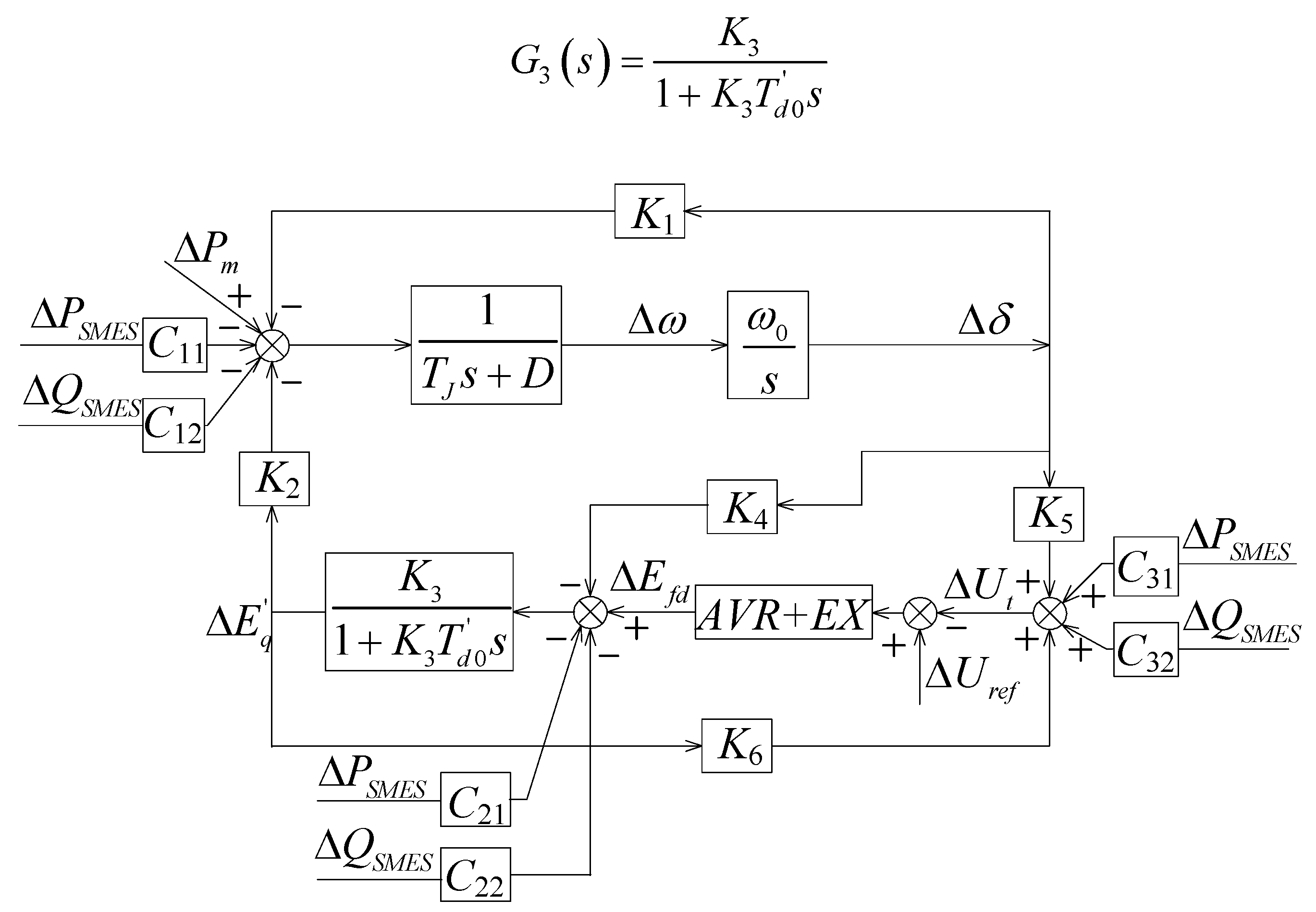
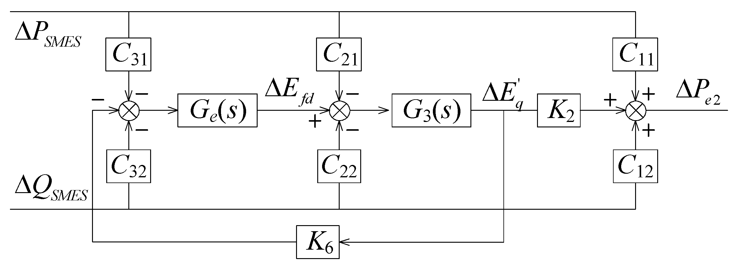
3.1. Transfer Function Derivation

The block diagram illustrated in Figure 4 can also be used to describe the model of the SMIB system with SMES. It can be found from the figure that the deviations of SMES power affect the generator in three aspects: electromagnetic power, armature reaction and terminal voltage. The effects of these three aspects are associated with C1i, C2i and C3i, respectively. The influence of SMES on the armature reaction further affects the electromagnetic power through the field circuit. The effect of SMES on the terminal voltage will affect the electromagnetic power through the automatic voltage regulator (AVR) and exciter (EX). Therefore, the total effect of SMES on the generator electromagnetic power is the sum of these three effects.
Extracting the parts related to ΔPSMES and ΔQSMES in Figure 4, the block diagram of the transfer function from the SMES power deviation to the electromagnetic power deviation can be drawn as Figure 5. From the figure, the transfer function from ΔPSMES and ΔQSMES to ΔPe2 can be derived as:
Δ P e 2 = ( C 11 K 2 G 3 ( C 21 + C 31 G e ) 1 + K 6 G e G 3 ) Δ P SMES + ( C 12 K 2 G 3 ( C 22 + C 32 G e ) 1 + K 6 G e G 3 ) Δ Q SMES
where G3(s) is the transfer function of the field circuit, as follows:
G 3 ( s ) = K 3 1 + K 3 T d 0 ' s
Figure 4. Block diagram of the SMIB system with SMES.
Energies 08 00656 g004
Figure 5. Block diagram from ΔPSMES and ΔQSMES to ΔPe2.
Energies 08 00656 g005
For the thyristor controlled excitation system with high gain AVR, the transfer function of the excitation system can be described as:
G e ( s ) = K A 1 + T E s
Substituting Equations (14) and (15) into Equation (13) and taking the characteristics of Ge(s) into consideration, Equation (13) can be simplified as:
Δ P e 2 ( C 11 K 2 / K 6 ( C 21 / K A + C 31 ) 1 + s T d 0 ' / ( K A K 6 ) ) Δ P SMES + ( C 12 K 2 / K 6 ( C 22 / K A + C 32 ) 1 + s T d 0 ' / ( K A K 6 ) ) Δ Q SMES
It can be found from Equation (16) that both ΔPSMES and ΔQSMES affect the electromagnetic power of the generator, and the degree of influence depends on Cii, which are determined by the SMES location and the operating conditions of the system. KA is usually much greater than one; thus, the effects of C21 and C22 are neglectable.

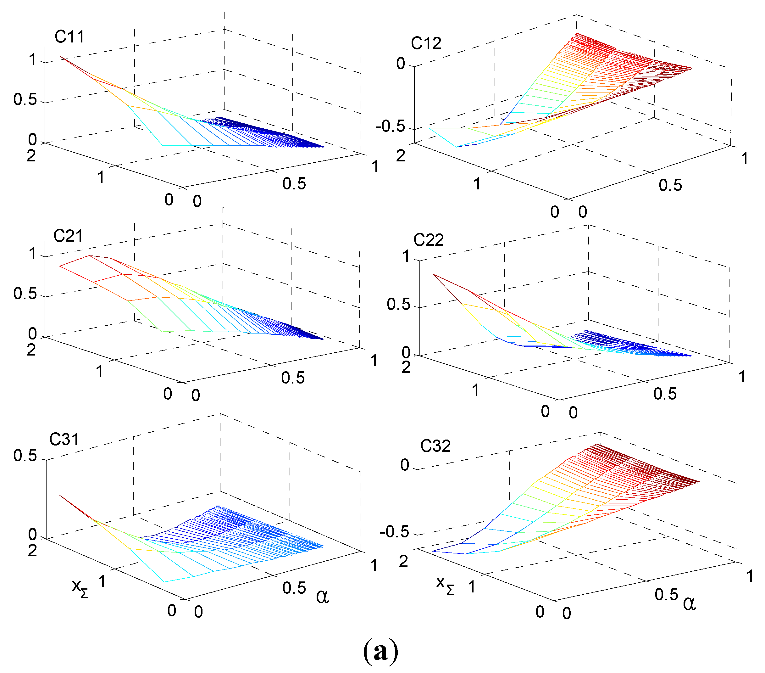
3.2. Characteristic Analysis of Cii

Equation (11) indicates that Cii is the function of α, xΣ and the system operating condition. Based on this function, the analysis of the impact of the SMES location, transmission system reactance and generator operating point on Cii is presented next.
When the active power output of the generator is 0.9 pu with power factor 0.95, the variation of Cii versus SMES location and transmission system reactance is shown in Figure 6a. It can be found that with the increase of α, the magnitude of C11 decreases, while the magnitude of C12 first increases and then decreases. The peak magnitude of C12 appears when α is about 0.3. The rise of xΣ increases the initial magnitude of C11 and C12, but accelerates the decay of C11. The magnitudes of the remaining four Cii have a similar behavior as C11, except they do not change so sharply.
Figure 6. Variation of Cii. (a) Cii vs. SMES locations; (b) Cii vs. generator output.
Energies 08 00656 g006aEnergies 08 00656 g006b
When SMES is installed at the generator terminal and the transmission system reactance is 0.65 pu, the variation of Cii versus the generator output power is shown in Figure 6b. From the figure, it can be found that the magnitudes of all Cii, except C22, increase with the rise of the active power of the generator. This indicates that the action of SMES on the generator is greater when the active power of the generator is high than that when the active power of the generator is low. However, the variation of the reactive power of the generator does not have so much of an influence on Cii. Figure 6 also shows that the magnitude of C11 is greater than C12 and the magnitude of C32 is greater than C31. This indicates that the direct influence of the ΔPSMES on the electromagnetic power of the generator is greater than that of ΔQSMES, while the influence of ΔQSMES on the generator terminal voltage is greater than that of ΔPSMES.

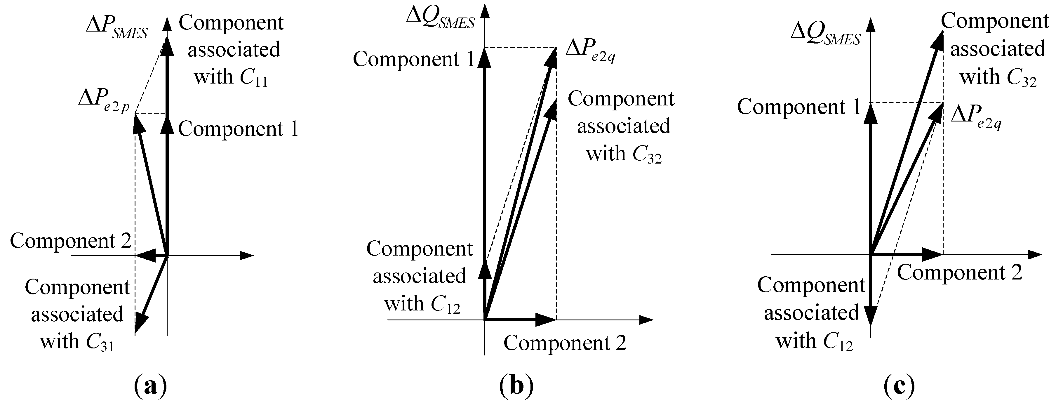
3.3. Efficacy of SMES on the Generator

It can be found from Equation (16) that ΔPe2 is the superposition of the action of ΔPSMES and ΔQSMES; thus, the total efficacy of SMES on the generator can be analyzed for active and reactive power separately.
Setting ΔQSMES to zero and neglecting C21 in Equation (16), ΔPe2 due to ΔPSMES is:
Δ P e 2 p ( C 11 C 31 K 2 / K 6 1 + s T d 0 ' / ( K A K 6 ) ) Δ P SMES
By denoting C11 = KC1C31 and substituting into Equation (17), the transfer function G1(s) from ΔPSMES to ΔPe2p can be denoted as:
G 1 ( s ) α 1 1 + β 1 T e q s 1 + T e q s
where Teq = T'd0/(KA·K6), α1 = C11C31·K2/K6 and β1 = 1/(1 − K2/(KC1·K6)).
It can be found from Figure 6 that C11 is five-times larger than C31, as long as the xΣ is greater than 0.65 and α1 is less than 0.3. Meanwhile, K2/K6 is mostly positive and in the range of 0.3~3 [20]; thus, β1 is in the range of 1~2.5, indicating that G1(s) is a phase lead element with the maximum leading phase around 30 degrees. Therefore, ΔPe2 can be decomposed into two components, as shown in Figure 7a: Component 1 is in phase with ΔPSMES, and Component 2 leads ΔPSMES by 90°. If ΔPSMES is in phase with Δω, Component 1 will provide the damping torque, while Component 2 will act as a negative synchronous torque.
Following the same process as above, ΔPe2 due to ΔQSMES can be found as follows:
Δ P e 2 q ( C 12 C 32 K 2 / K 6 1 + s T d 0 ' / ( K A K 6 ) ) Δ Q SMES
By denoting C12 = KC2C32 and substituting into Equation (19), the transfer function G2(s) from ΔQSMES to ΔPe2q can be denoted as:
G 2 ( s ) α 2 1 + β 2 T e q s 1 + T e q s
where α2 = C12C32·K2/K6 and β2 = 1/(1 − K2/(KC2·K6)).
Figure 7. Components of ΔPe2p and ΔPe2q. (a) ΔPe2p; (b) ΔPe2q when the output of the generator is low; (c) ΔPe2q when the output of the generator is high.
Energies 08 00656 g007
It can be found from Figure 6b that when the active power of the generator is low, C12 is positive and C32 is negative; otherwise, both C12 and C32 are negative. The magnitude of C32 is greater than that of C12 for any output of the generator. When C12 is positive and C32 is negative, the decomposition of ΔPe2q is shown in Figure 7b. It can be found that ΔPe2q leads the component associated with C32 by some degree and has a little larger magnitude than that component. As the maximum value of the lag phase of the component associated with C32 to ΔQSMES is 90°, the phase lag of ΔPe2q to ΔQSMES is within 90°. When both C12 and C32 are negative, the decomposition of ΔPe2q is shown in Figure 7c. It can be found that ΔPe2q lags the component associated with C32 by some degree and has a little smaller magnitude than that component. In this case, the phase lag of ΔPe2q to ΔQSMES may exceed 90°. Therefore, G2(s) has a lag phase characteristic, whether the generator’s active power is high or low.
It can be found from Figure 7 that the effect of ΔPSMES on the generator is mainly through directly affecting the electromagnetic power, while that of ΔQSMES is mainly through AVR. The former effect is mainly related to C11, while the latter one is mainly related to C32. From the phase relationships of the components in the figure, it can also be found that the AVR is favorable to the action of ΔQSMES, but unfavorable to that of ΔPSMES. Therefore, the most suitable location for SMES is found as follows: When the generator is equipped with the AVR whose gain is great, the most suitable location is the generator terminal where both C11 and C32 have the greatest magnitude, whether ΔPSMES, or ΔQSMES, or both of them are used to improve the system dynamic performance. When there is no AVR or the gain of the AVR is small, the most suitable location is the point where C12 has the greatest magnitude if only ΔQSMES is used, while the generator terminal is the most suitable location if only ΔPSMES is used.

4. SMES-Based Damping Controllers Design

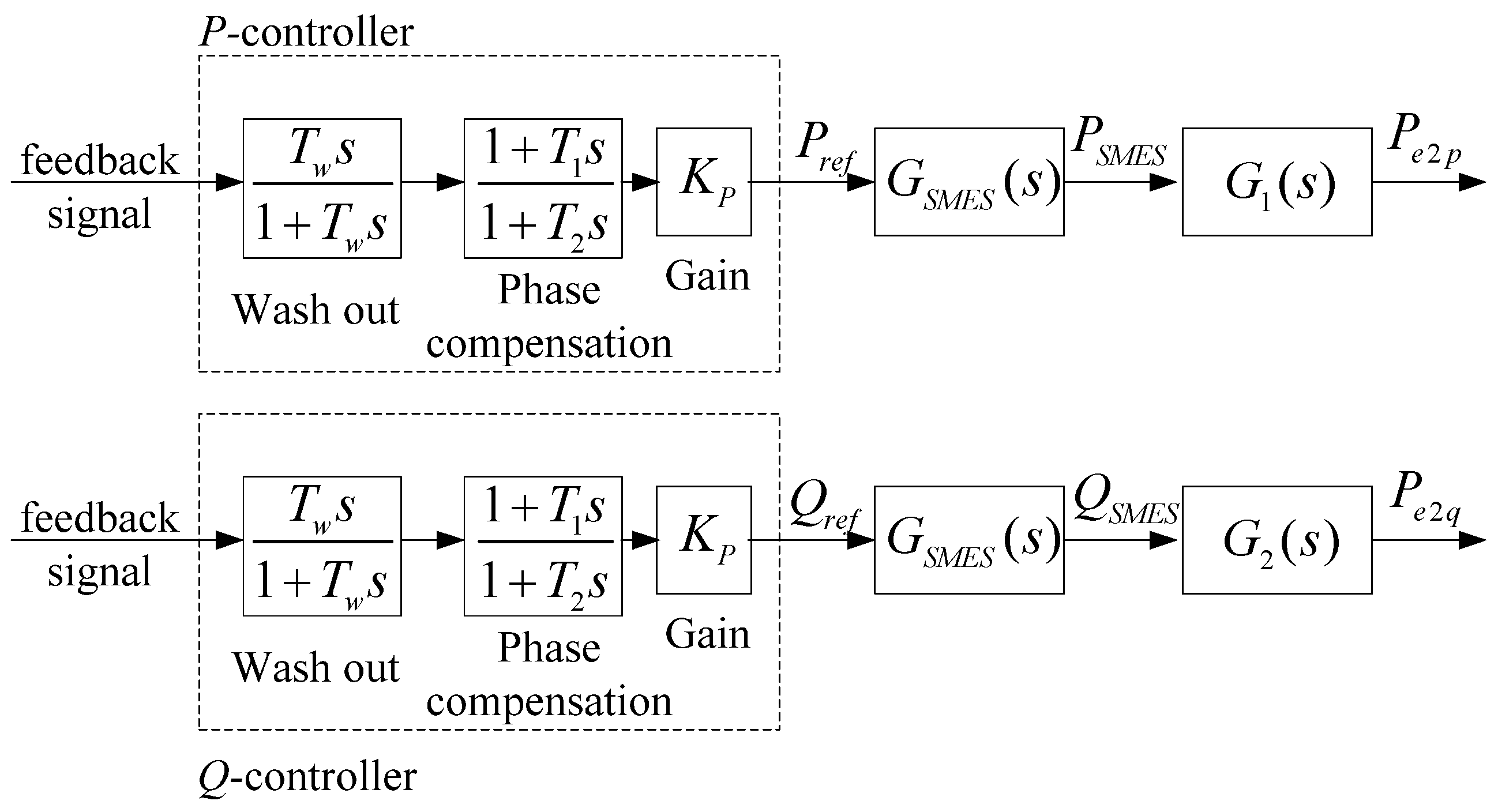
4.1. Controller Structure and Parameters Determination

From Figure 7, it can be found that ΔPe2p is not in phase with ΔPSMES, and ΔPe2q is not in phase with ΔQSMES either. In order to fully harness the potential of SMES to improve the system damping, the phase compensation method can be adopted. This method utilizes the same structure as PSS, which is also designed based on the phase compensation method [21,22], for the controller of active power regulation (P-controller) and the controller of reactive power regulation (Q-controller). These controllers are shown in Figure 8 and consist of three blocks: a washout block, a phase compensation block and a gain block. The washout block makes sure that the SMES power regulation responds to the inputs’ changes, excluding the steady-state offset. The phase compensation block provides appropriate phase compensation to regulate ΔPe2p and ΔPe2q in phase with Δω. The gain block determines how much damping is added to the system and has a significant impact on the SMES power rating required.
Figure 8. Block diagram of SMES controllers.
Energies 08 00656 g008
When Δω is used as the feedback signal, the phase compensation block of the P-controller is a phase lag element. It may lag a bit more than needed to makes sure that both damping and synchronous torques are positive. If the lag phase of SMES dynamics represented by GSMES(s) is equal to or greater than the phase leading of G1(s), the phase compensation block can be saved or become a phase lead block. As ΔPe2q lags ΔQSMES and GSMES(s) has phase lagging characteristics, the phase compensation block of the Q-controller should be always a phase lead element, and in some situations, more than one block may be needed.
Simplifying the block diagram shown in Figure 4 and taking transfer functions of SMES, P-controller and Q-controller into account, the feedback control diagram of SMES can be found as shown in Figure 9; where Ggen(s) is the transfer function of the generator from the electromagnetic torque to the rotor angular velocity, and it contains the effect of synchronous torque and the excitation system. H(s) is the transfer function from Δω to the feedback signal used for control, and when Δω is used as feedback, its value is unity. Gcp(s) and Gcq(s) are the transfer functions of the P-controller and the Q-controller, respectively. All of the transfer functions in Figure 9 are calculated; the polar form or the rectangular form of pole placement on the root locus can be used to calculate the parameters of the P-controller and the Q-controller.
Figure 9. Feedback control diagram of SMES.
Energies 08 00656 g009

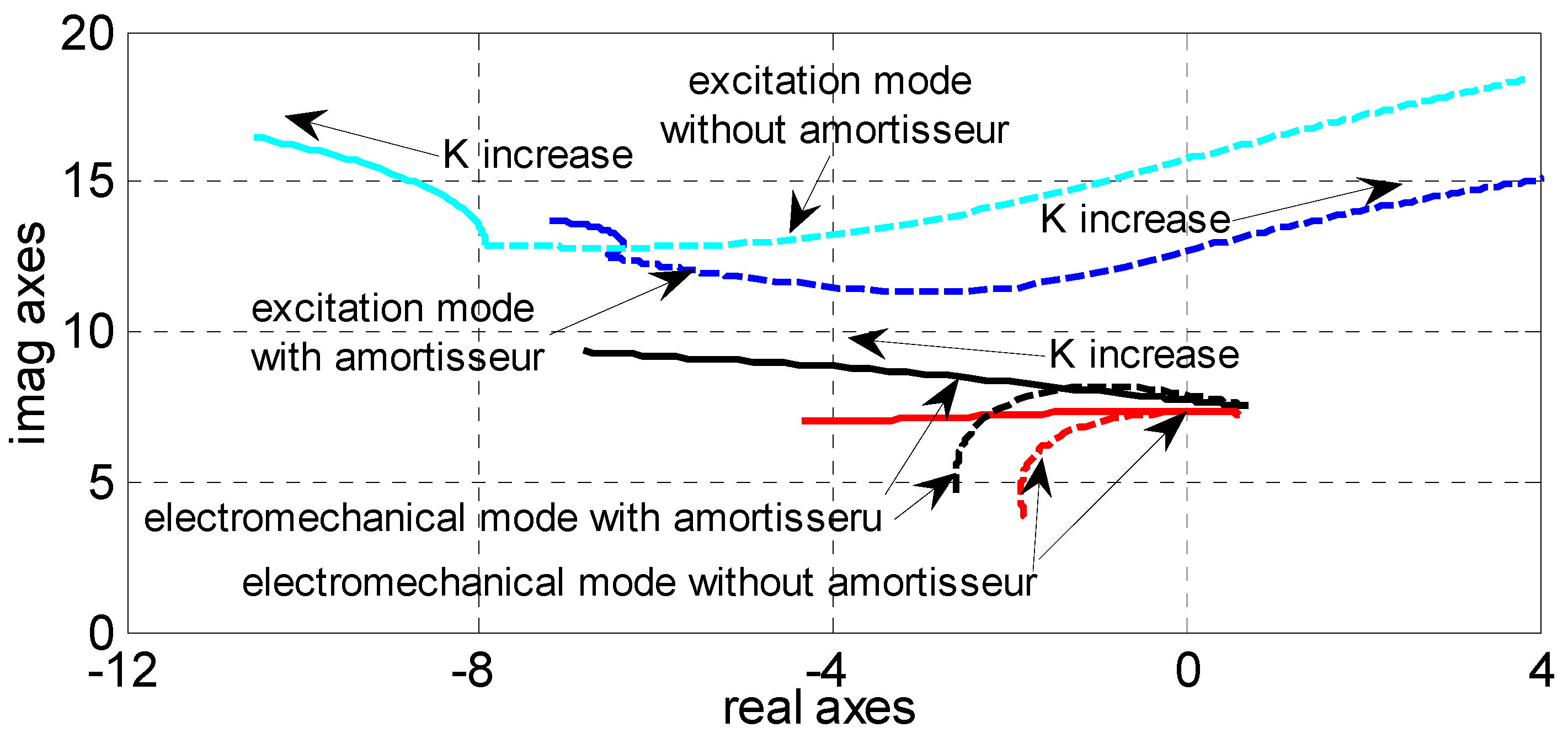
4.2. Effect of Amortisseur

The previous derivations of G1(s) and G2(s) do not include the effect of the amortisseur. However, the amortisseur has an impact on the G1(s) and G2(s) and further has an effect on the damping improvement of SMES. Figure 10 shows the root locus of excitation and the electromechanical mode with and without taking the amortisseur effect into consideration when the gains of the P-controller and the Q-controller vary, respectively. The root locus is plotted on the following conditions:
(1)
Generator output: Pg = 0.9 pu, Qg = 0.3 pu;
(2)
Grid connected reactance: x1 = 0, x2 = 0.65;
(3)
Parameters of the P-controller: Tw = 1.4 s, T1 = 0.08 s, T2 = 0.24 s;
(4)
Parameters of the Q-controller: Tw = 1.4 s, T1 = 0.3 s, T2 = 0.06 s;
(5)
Detailed parameters of the generator and the excitation system are given in the Appendix.
By comparing the red lines with the black ones, it is found that the amortisseur changes the initially-designed P-controller from full compensation to overcompensation and changes the initially-designed Q-controller from full compensation to undercompensation. Combining this observation with Figure 7, it can be found that the amortisseur weakens the action of the C31 path, reducing the phase leading of G1(s), and weakens the action of the C32 path, increasing the phase lag of G2(s). It can be found from Figure 7 that the action associated with C3i is primarily related to the AVR. Therefore, the above observations indicate that the amortisseur partly counterbalances the effect of the AVR, thus enhancing the effect of ΔPSMES on the electromechanical mode and weakening that of ΔQSMES.
Figure 10. Main root locus vs. the gain of the controller (solid line: P-controller only; dotted line: Q-controller only).
Energies 08 00656 g010
In order to design controllers with appropriate phase compensation, the effect of the amortisseur should be considered particularly. Fortunately, this can be done by adjusting the degree of phase compensation. Through trial and error, it is found that the degree of compensation should be in the range of 0.4–0.8 for the P-controller and in the range of 1–1.5 for the Q-controller. The exact value can be found by observing the exit angle in the root locus of the electromechanical mode as in the PSS parameter adjustment [23].

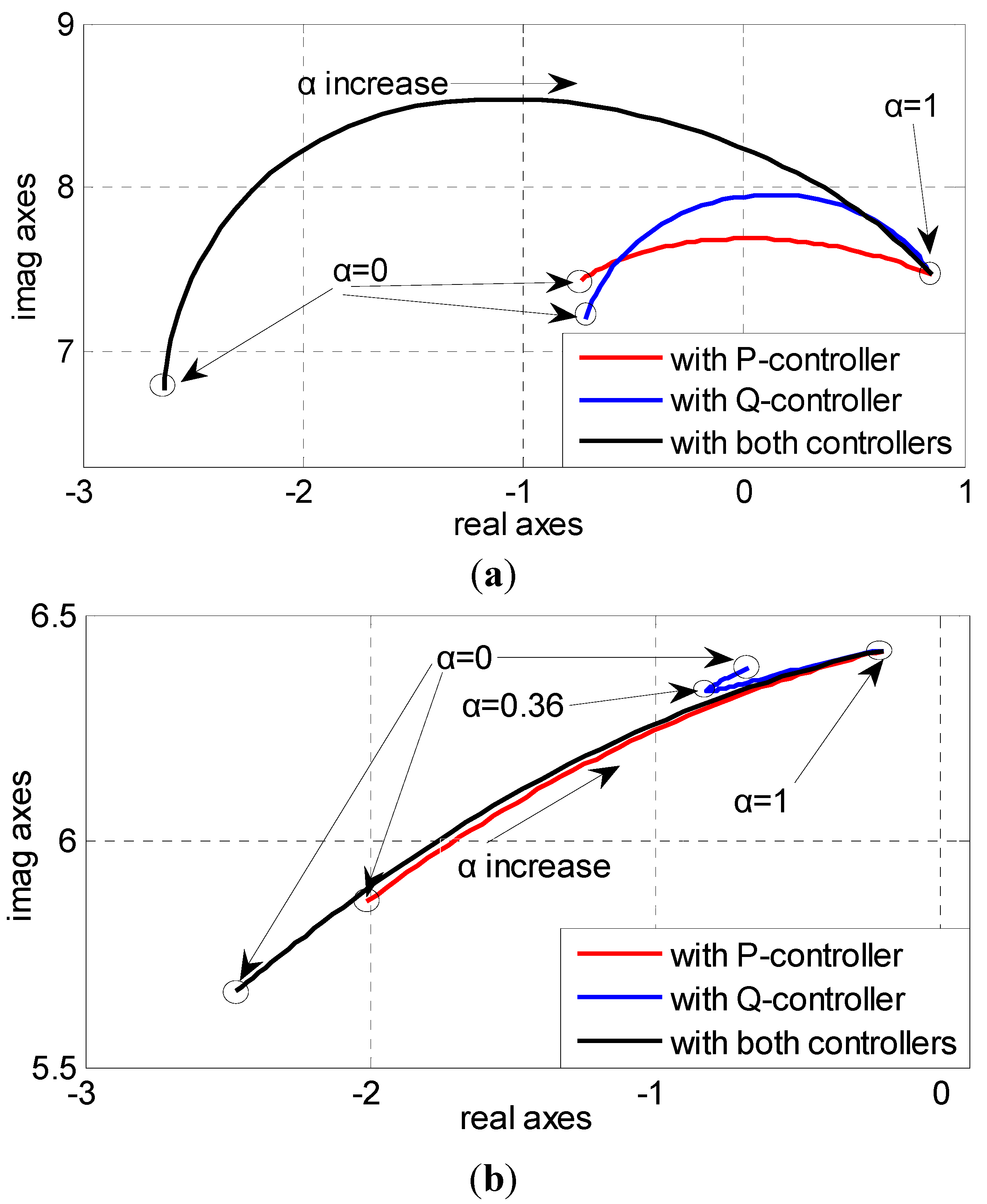
4.3. Influence Factors in Terms of Damping Improvement

Generally, the design of SMES controllers is accomplished based on specific system parameters. However, many factors, such as the location of SMES, transmission system reactance, dynamic characteristics of SMES and system operating point, can affect the damping improvement of SMES. These effects are investigated through the root locus in the following analysis. The system parameters for these analyses are the same as in Section 4.2.

4.3.1. Influence of SMES Location

Figure 11 shows the root locus of the electromechanical mode when location factor α varies. Figure 11a shows the root locus when the generator is equipped with high gain AVR. It can be found from the figure that with the increase of α, the damping ratio decreases for the system with SMES controlled by the P-controller, or the Q-controller, or both. Figure 11b shows the root locus when the AVR is out of service. Only proportional controllers are utilized in this situation. It can be found that with the rise of α, the damping ratio of the system with SMES controlled by the Q-controller first increases and then decreases; and it reaches the maximum value when α equals 0.36. However, the damping of the system with SMES controlled by the P-controller or both controllers monotonically decreases. By comparing Figure 11a,b, it can be found that the damping improvement of the Q-controller is obviously more effective in the system with the AVR than that without the AVR. These observations are consistent with the analysis conclusions mentioned before in Section 3.3.
Figure 11. Root locus vs. SMES locations. (a) Generator equipped with the automatic voltage regulator (AVR); (b) generator not equipped with the AVR.
Energies 08 00656 g011

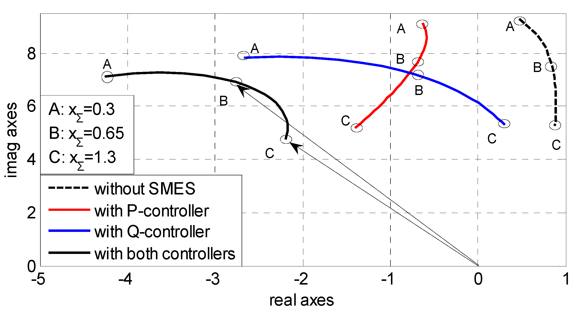
4.3.2. Influence of Transmission Reactance

Figure 12 shows the root locus of the electromechanical mode versus xΣ variation when SMES is installed at the generator terminal. It can be found that the damping ratio and oscillation frequency of the system without SMES decrease with the increase of xΣ. The damping of the system is improved by SMES, and the improvement by SMES with the P-controller is more and more effective with the increase of xΣ, while the opposite is true for the improvement by SMES with the Q-controller. When SMES with both controllers is applied, the impact of xΣ on the Q-controller is partly counterbalanced by the P-controller in Segment B–C; therefore, the damping improvement is almost independent of the variation of xΣ. In Segment A–B, the system damping ratio increases obviously by SMES with the Q-controller. However, in this situation, the excitation mode will be the dominant mode, as its damping is deteriorated heavily by the SMES controller by the Q-controller. Therefore, the Q-controller needs to be redesigned in this segment.
Figure 12. Root locus vs. grid connected reactance.
Energies 08 00656 g012

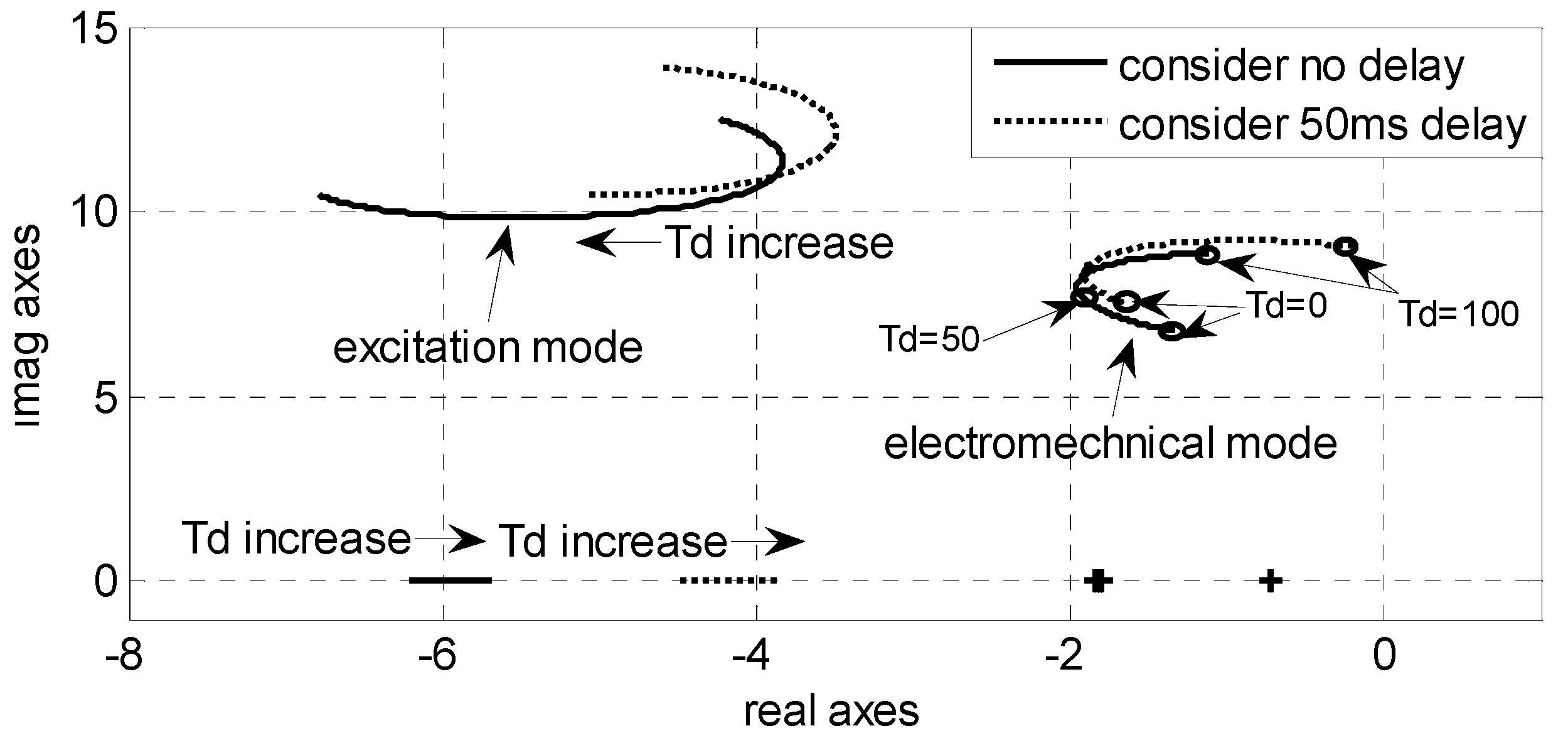
4.3.3. Influence of SMES Dynamic Characteristics

Generally speaking, the dynamic characteristics of SMES, represented by Equation (5), only have the poles away from the imaginary axis. Therefore, they have little influence on the dynamics of the SMIB system. However, the delay time (like delay of communication and filters) of the whole control loop, which is much larger than the time constant related to the VSC, may have a significant impact on the system dynamics. Figure 13 shows the main root locus when the delay time varies from 0 to 100 ms.
Figure 13. Root locus vs. delay time.
Energies 08 00656 g013
Two groups of SMES controllers are used: one group is designed considering no delay; another is designed considering a delay time of 50 ms. It can be found that the control delay affects the electromechanical mode and excitation mode significantly, but has little impact on other modes. When the actual delay time differs from the value used in the controller design, the damping improvement is weakened obviously. Therefore, it is important to calculate the value of the delay for the controller design as precisely as possible. If the precise value is difficult to determine or it varies in a range, the average value should be used for the robustness of the controllers against the delay variation.

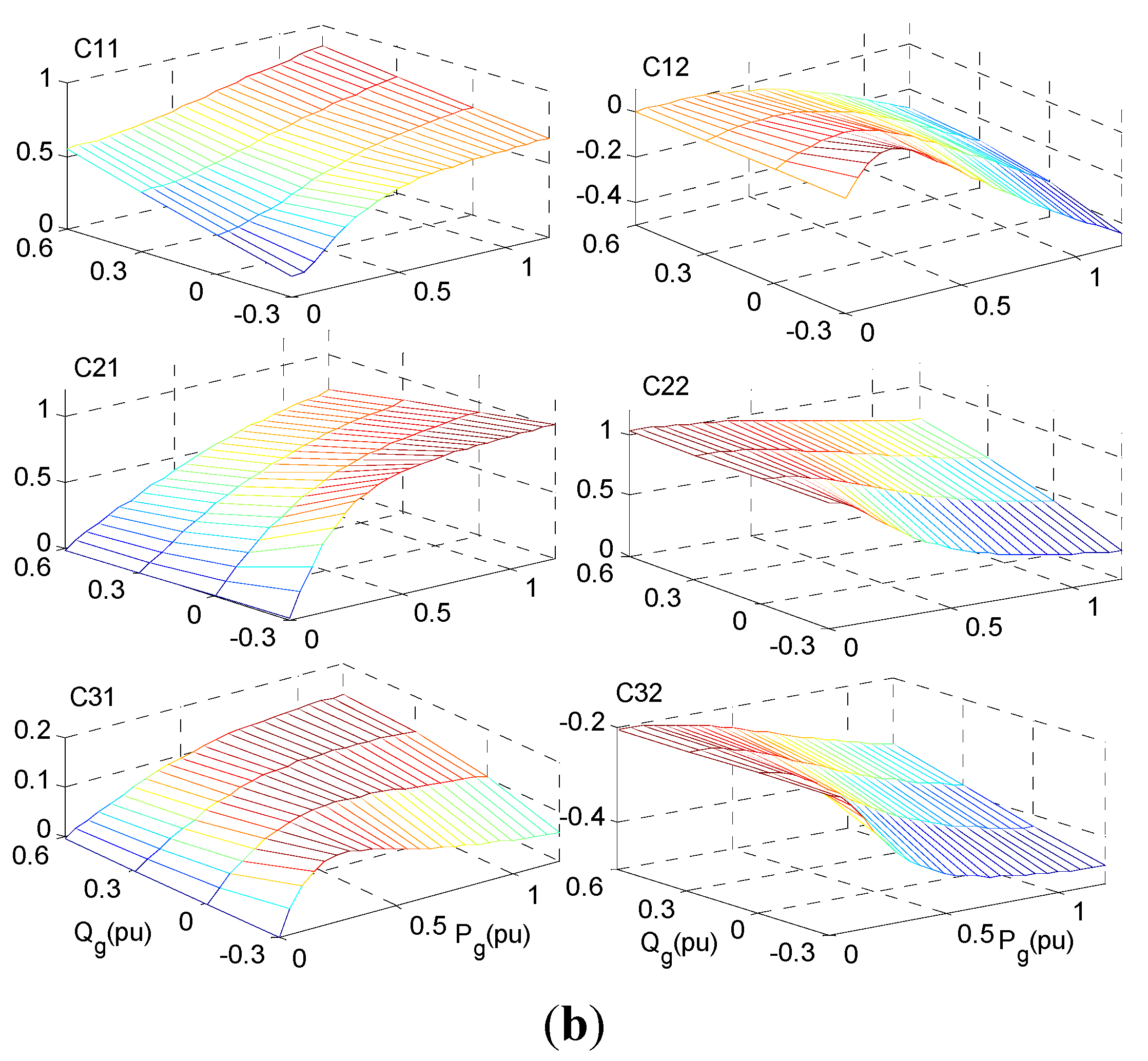
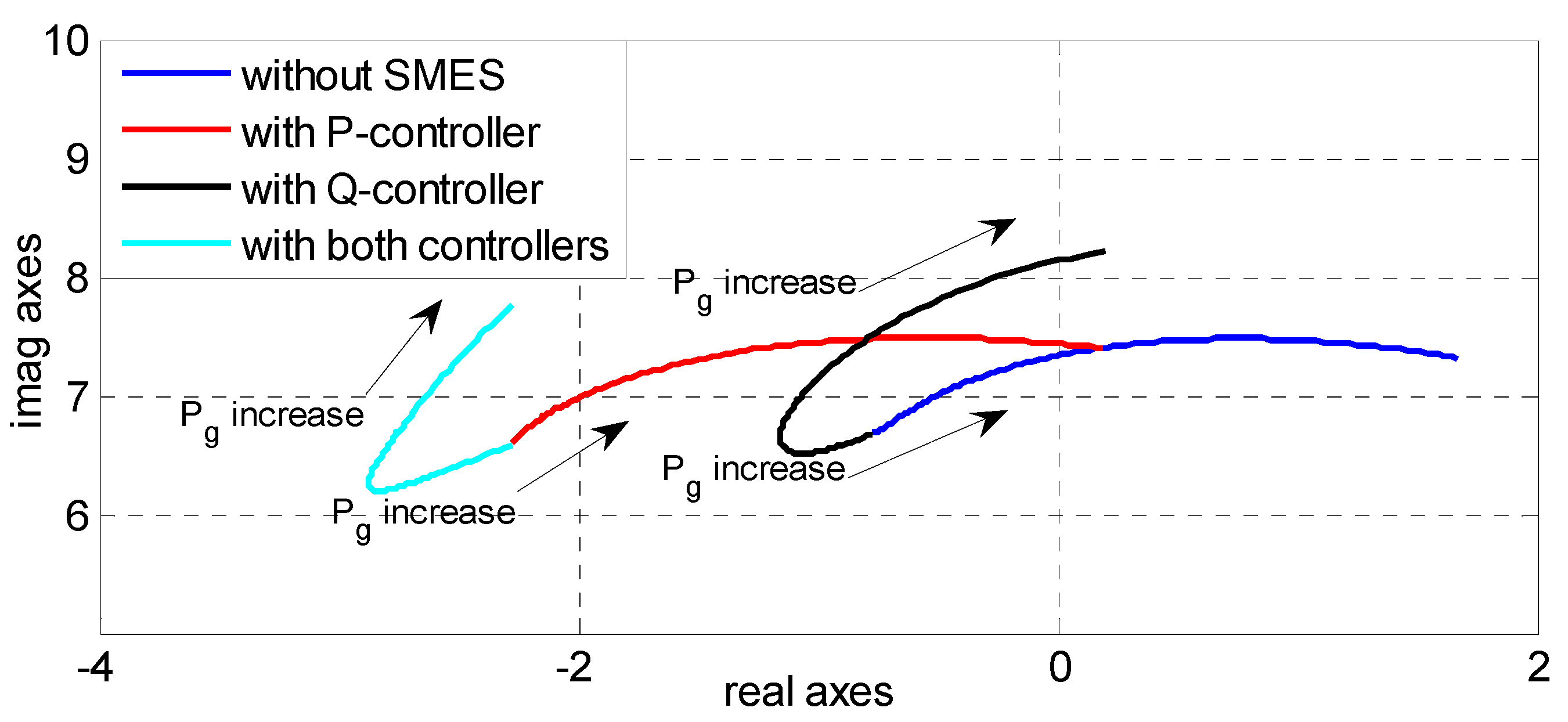
4.3.4. Influence of Generator Output

Figure 14 shows the root locus of the electromechanical mode when Pg varies from 0 to 1.2 pu. It can be found from the figure that the damping ratio obviously decreases and the oscillation frequency slightly increases with the increase of Pg. When SMES with the P-controller is applied, the poles are shifted left, and the variation of Pg has little effect on this shift. When SMES with the Q-controller is applied, the poles are also shifted left. However, the pole shift decreases as Pg decreases and becomes zero when Pg equals zero. When both the P-controller and Q-controller are applied, the pole shift is a little higher than the sum of the individual shifts. The shift pattern indicates that SMES with either the P-controller or Q-controller can improve the system damping, and applying them together is much more effective than applying any of them individually. Besides, the SMES with the P-controller is more robust than the SMES with the Q-controller against the variation of Pg to improve the system damping.
Figure 14. Main root locus vs. generator active power output.
Energies 08 00656 g014

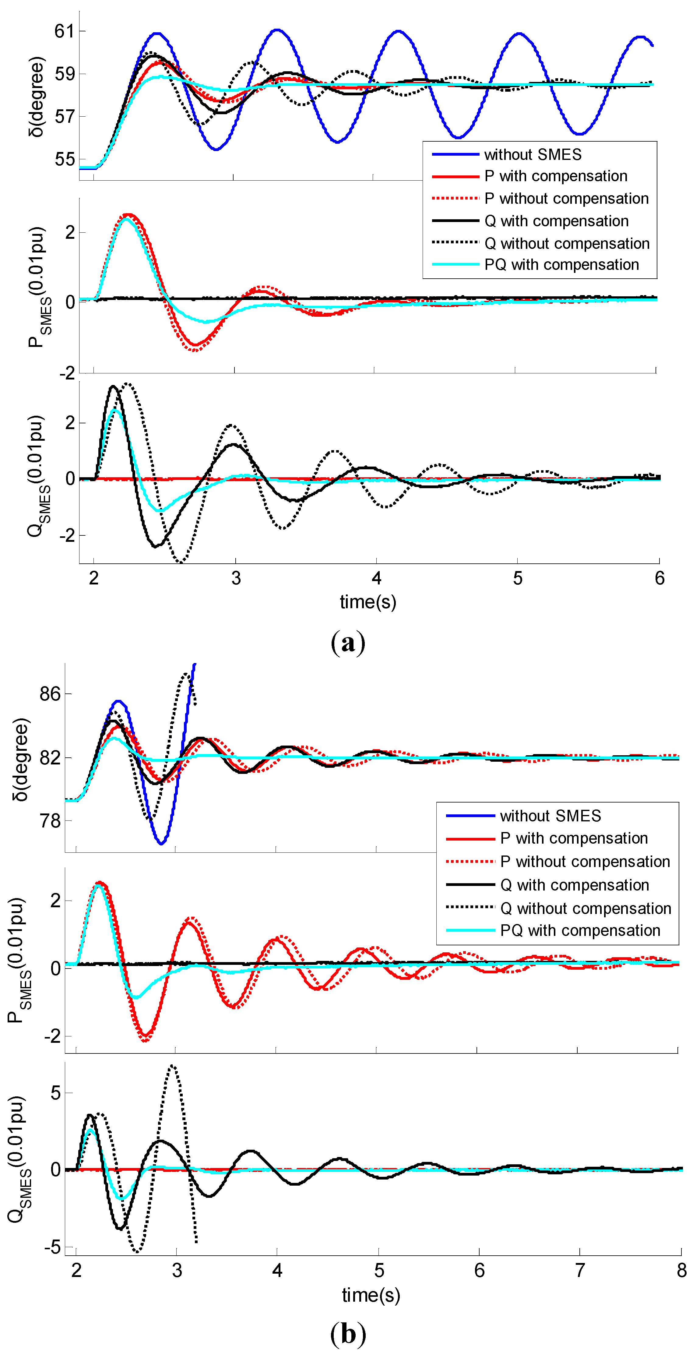
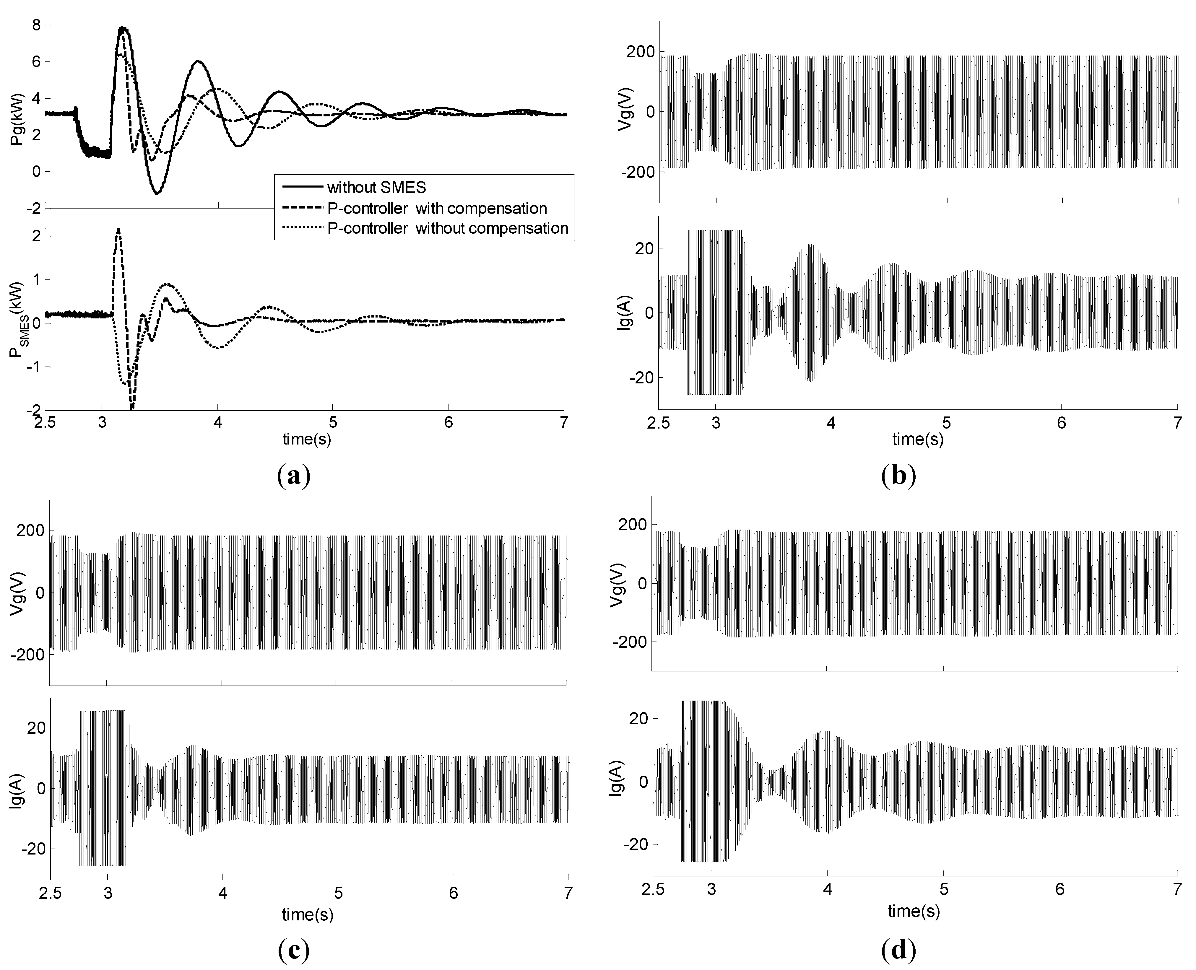
5. Simulation Results

To validate the theoretical analysis of the mechanism and the effectiveness of the proposed controllers for SMES, simulation analysis of the SMIB system depicted in Figure 3 is carried out by using PSCAD/EMTDC software (Manitoba HVDC Research Centre, Manitoba, Canada). The detailed parameters of the generator and excitation system are given in the Appendix, and the parameters of the controllers are depicted in Table 1. The controllers utilize rotor angular velocity as the feedback signal, and the controller parameters are determined by the method proposed above. The bases of the per-unit system used in the simulation are 500 kW and 1 kV. The following two scenarios are considered:
  • Scenario 1: Pg = 0.5 pu, Qg = 0.16 pu;
  • Scenario 2: Pg = 0.85 pu, Qg = 0.265 pu.
Table 1. Parameters of the controllers used in the simulation.
Different ControllersWashout BlockCompensation BlockGain BlockEffective Gain *
TwT1T2KpKeff
P-controllerwith compensation (1 block)1.4 s0.1071 s0.1757 s4434.3
without compensation1.4 s3534.3
Q-controllerwith compensation (2 blocks)1.4 s0.2478 s0.0765 s12.640.8
without compensation1.4 s4140.8
Both P and Q control with compensationP-controller (1 block compensation)1.4 s0.1071 s0.1757 s4434.3
Q-controller (2 blocks compensation)1.4 s0.3014 s0.0624 s17.840.8
* Effective gain: gain from the feedback signal to the SMES output power at oscillation frequency.
Figure 15 illustrates the system response to a 0.05 pu step change of the mechanical torque at 2 s, and Table 2 gives the eigenvalues of the electromechanical mode of the two scenarios. The eigenvalues and system response of the P-controller and Q-controller without compensation are also given for comparison.
Figure 15. Simulation results of the response of the SMIB system to a 0.05 step change of the mechanical torque. (a) Scenario 1: Pg = 0.5 pu, Qg = 0.16 pu; (b) Scenario 2: Pg = 0.85 pu, Qg = 0.265.
Energies 08 00656 g015
Table 2. Eigenvalues of the electromechanical mode of the SMIB system under two scenarios.
Different ControllersScenario 1Scenario 2
Eigenvaluesξω d (Hz)Eigenvaluesξω d (Hz)
Without SMES−0.10 ± j 7.290.0141.160.85 ± j 7.47−0.1141.20
P-controllerwith compensation−1.74 ± j 7.140.2441.14−0.74 ± j 7.440.0991.18
without compensation−1.58 ± j 6.650.2371.06−0.65 ± j 7.020.0931.12
Q-controllerwith compensation−1.06 ± j 6.640.161.06−0.72 ± j 7.190.1021.15
without compensation−0.32 ± j 8.60.1171.380.74 ± j 8.99−0.0821.43
P-controller and Q-controller with compensation−2.36 ± j 6.130.461.0−2.70 ± j 6.790.41.08
In Scenario 1, the damping ratio of the original system is low. The oscillation induced by changing the mechanical torque takes dozens of seconds to decay. When SMES is applied, the system damping ratio is increased remarkably. The oscillation decay time is reduced to about 2 s by SMES controlled by the P-controller with compensation, about 3 s by SMES controlled by the Q-controller with compensation and about 1.5 s by both of them. The removal of the compensation in the P-controller weakens the damping improvement and decreases the oscillation frequency slightly. However, the removal of the compensation in the Q-controller weakens the damping improvement and increases the oscillation frequency obviously. The difference of damping improvement between the controller with and without compensation indicates that the induced electromagnetic power of the generator by SMES leads to the deviation of SMES active power by a small angle, but lags the deviation of the SMES reactive power by a large angle.
In Scenario 2, the damping ratio of the original system becomes negative due to the increase of the generator output, and the generator would fall out of step after the disturbance. SMES controlled by the P-controller or the Q-controller with compensation can stabilize the system and reduces the oscillation decay time to about 6 s. SMES controlled by the P-controller without compensation also can stabilize the system, while the damping improvement is weakened and the oscillation frequency is decreased slightly. However, SMES controlled by the Q-controller without compensation cannot stabilize the system. When SMES is controlled by both the P-controller and Q-controller, the oscillation is damped out within 1.5 s.
By comparing the results of Scenario 1 and Scenario 2, it can be found that SMES with either the P-controller or Q-controller can improve the system damping under different system conditions. The appropriate phase compensation makes SMES more effective at improving the damping of the SMIB system. As SMES with the P-controller provides almost invariant damping improvement in both scenarios, while SMES with the Q-controller provides less damping improvement in Scenario 1 than Scenario 2, it can be concluded that the former one is more robust than the latter one against different system conditions. SMES with both the P-controller and Q-controller is more effective than SMES with either an individual controller and even better than their linear sum. The damping improvement of applying SMES with both controllers is also not as sensitive as that of applying SMES with the Q-controller to the variation of the system operating conditions. Besides, applying SMES with both the P-controller and Q-controller decreases the peak value of the active and reactive power output of SMES, therefore reducing the requirement of SMES power rating.

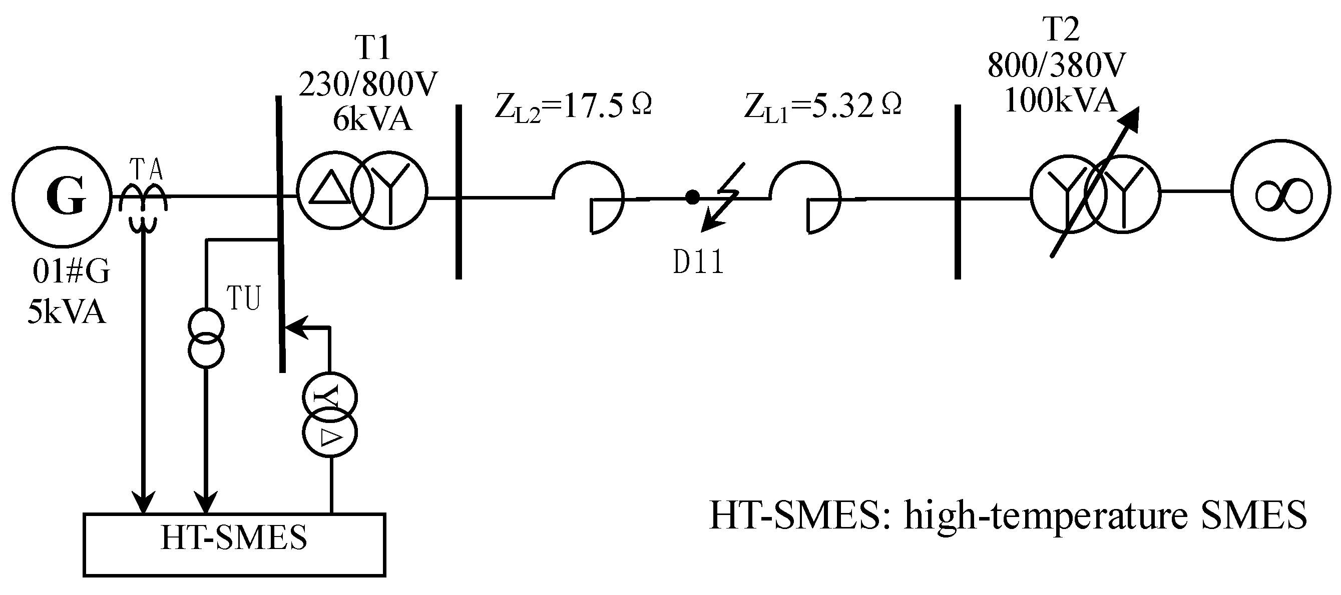
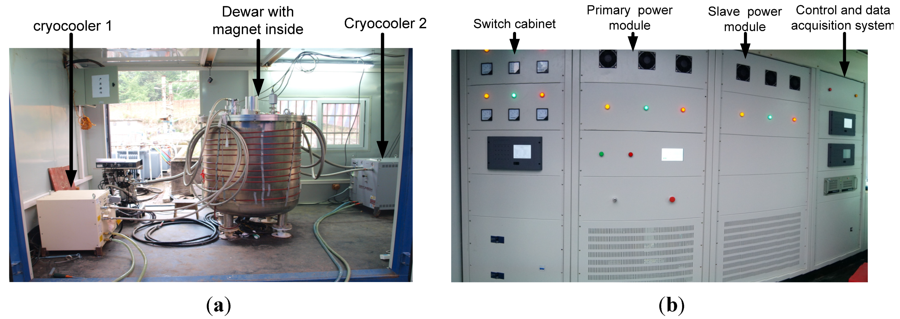
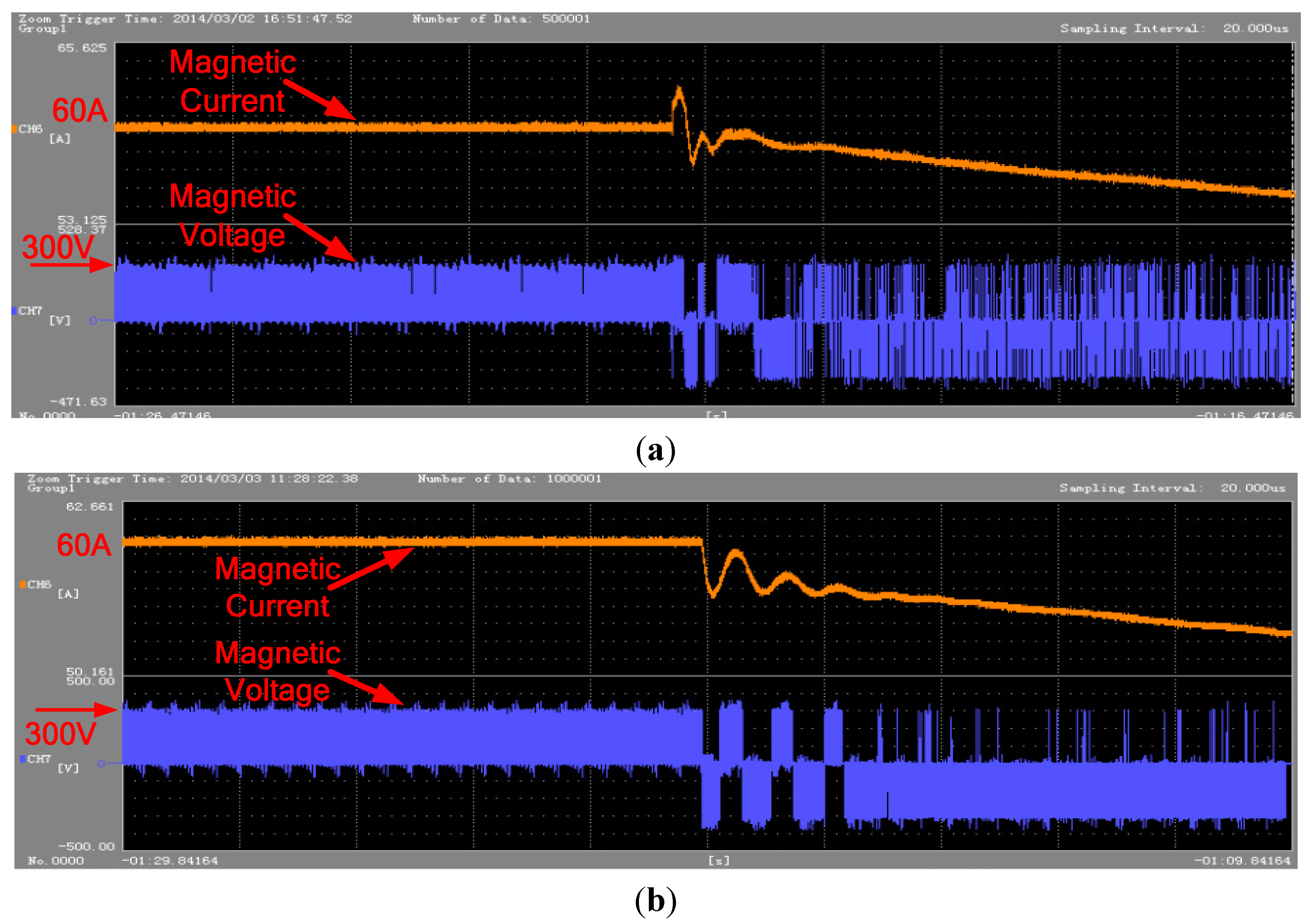
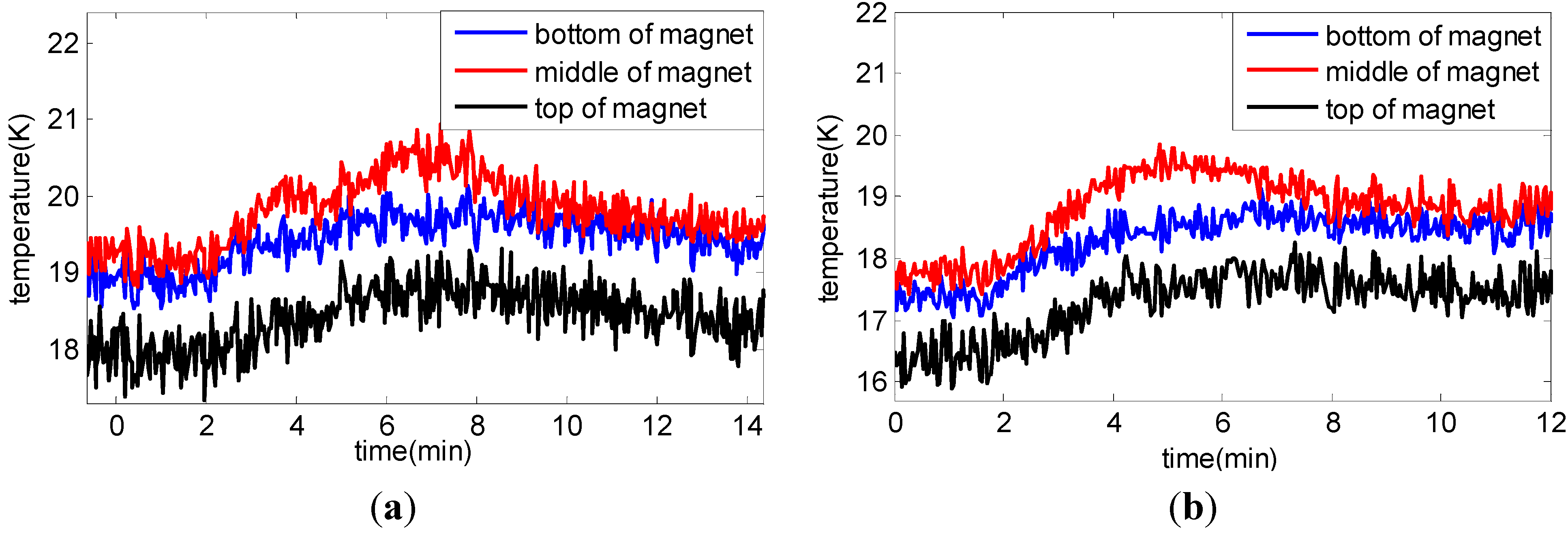
6. Experimental Validation

Laboratory experiments are carried out to evaluate the theoretical analysis and controller design method related to the active power regulation, as well as the effectiveness of employing SMES to enhance power system stability. The single-line diagram of the experimental system is displayed in Figure 16. The system simulates a 25-MW generator connected to the grid through a 110-kV transmission line of a 340-km length. The 150-kJ/100-kW high-temperature SMES (HT-SMES) device used in the experiments is shown in Figure 17, and its main parameters are given in Table 3. The HT-SMES comprises a superconductive magnet with auxiliary equipment and a PCS. The detailed parameters of the generator can be found in the Appendix. The generator outputs 3.2 kW of active power and 0.9 kVar of reactive power during the steady state in the experiments.
Figure 16. Single-line diagram of laboratory experimental system.
Energies 08 00656 g016
Figure 17. (a) Superconductive magnet with auxiliary equipment; (b) power conditioning system.
Energies 08 00656 g017
Table 3. Main parameters of the SMES device.
Rating EnergyMaximum Active PowerRating DC CurrentRating DC VoltageRating AC VoltageInductance of CoilRating TemperatureCoil StructureHeight of Coil
150 kJ100 kW175 A600 V300 V9.7 H20 Ksingle-solenoid210.99 mm
The experiments are carried out by applying a three-phase-to-ground fault at D11, as shown in Figure 16, for 300 ms. The responses of the system and the SMES device are depicted in Figure 18, Figure 19 and Figure 20. Due to the limit of the measurement equipment, the active power of the generator is used as the feedback signal for the SMES controllers. The parameters of the compensation block are also calculated for it. Figure 18 shows the active power of the generator and SMES, the current and the voltage of the generator. It can be seen that the system damping is remarkably improved by SMES. The oscillation time is reduced from 4 to 1.5 s by applying SMES controlled by the P-controller with appropriate phase compensation. If the phase compensation block is removed in the P-controller, both the damping ratio and oscillation frequency will decrease. The envelopes of the stator current of the generator in Figure 18b–d also confirm these observations.
Figure 18. (a) Active power of the generator and SMES; (b) voltage and current of the generator without SMES; (c) voltage and current of the generator using the P-controller with compensation; and (d) voltage and current of the generator using the P-controller without compensation.
Energies 08 00656 g018
Figure 19. Current and voltage of the magnet. (a) Using the P-controller with compensation; (b) Using P-controller without compensation.
Energies 08 00656 g019
Figure 20. Temperature of the magnet: (a) using the P-controller with compensation; (b) using the P-controller without compensation.
Energies 08 00656 g020
Figure 19 illustrates the current and voltage of the superconductive magnet of the SMES device during the experiments. The magnet is charged to 60 A and then stays in standby mode. When the fault is applied, energy stored in the magnet is used to stabilize the system for 5 s. Then, the magnet is discharged to zero with the setting speed. Comparing Figure 18a with Figure 19, it can be found that the waveforms of the magnet currents are almost the same as that of the active power commutated between SMES and the grid during the 5 s after the clearance of the fault. This observation is consistent with the analysis in Section 2.1.
Figure 20 illustrates the temperature of different parts of the magnet for each experiment. It can be found that the temperature rises during and after the experiments. The middle part of the magnet has the highest rise, while the top part has the lowest rise. However, the temperature of all parts for each experiment is within the design constraints, indicating that the SMES system operates in good conditions.

7. Conclusions

This paper proposes the transfer function of SMES and a small signal model of the SMIB system with SMES, based on which the action mechanism of SMES on the generator dynamics is analyzed. The P-controller and Q-controller for SMES to improve the system damping are designed by using the phase compensation method. The influence of factors, such as transmission system reactance, the dynamics of SMES and the system operating conditions, on the SMES performance is investigated, as well. The analysis of the SMES action mechanism in the SMIB system indicates that the induced electromagnetic power of the generator by SMES leads to the deviation of the active power of SMES by a small angle, while lagging the deviation of the reactive power of SMES by a relatively large angle. The analysis also indicates that when the generator is equipped with a high gain AVR, the best location for SMES to improve the damping of the SMIB system is the generator terminal, whether the regulation of the active power, or that of the reactive power, or both of them are used. However, when there is no AVR or the gain of the AVR is low, the best location is the point that is about 30% of the electric distance of the whole transmission system from the generator, if only reactive power regulation is used. If active regulation or both active and reactive regulation are used, the generator terminal is still the best location.
The eigenvalue calculation and simulation results demonstrate that the P-controller and the Q-controller for SMES improves the damping of the SMIB system and can be designed independently using the phase compensation method. SMES with either the P-controller or Q-controller can improve the damping of the SMIB system effectively in different conditions. Applying SMES with both the P-controller and the Q-controller makes the damping improvement more effective than SMES with an individual controller and decreases the peak value of the active and reactive power output of SMES. Therefore, it can reduce the rating power requirement of SMES. In addition, SMES with the Q-controller is less robust than SMES with the P-controller against the variation of the system operating conditions.
The results of physical experiments in the lab indicate that SMES with the proposed controllers effectively enhances the damping and transient stability of the system. In addition, the two simulation scenarios show that SMES with even less than 10% of the capacity of the generator can remarkably increase the system damping. This validates the feasibility of SMES in practical applications.

Acknowledgments

This work was supported by Hubei Electric Power Research Institute of the State Grid and the National Natural Science Foundation of China (51207063).

Author Contributions

Xiaohan Shi, Wei Yao and Asad Waqar do the theory analysis and simulation. Xiaohan Shi and Wenping Zuo design and realize the laboratory test. The whole work was carried out under the advisement of, and with regular feedback from Shaorong Wang and Yuejin Tang.

Nomenclature

Symbols related to the model of SMES:
R, L
equivalent parameters of the AC source
ea, eb, ec
instantaneous value of source fundamental voltages
ia, ib, ic
instantaneous value of source fundamental currents
ua, ub, uc
instantaneous value of inverter fundamental voltages
ed, eq
dq components of source fundamental voltages
id, iq
dq components of source fundamental currents
Md, Mq
dq components of modulation index
ω
frequency of the AC source
udc
voltage of the capacitor
idc
current from the three-phase bridge to the capacitor
iChopper
current from the capacitor to the chopper
icoil
current of the superconductive coil
QC, QCref
energy stored in the capacitor and its reference
QL, QLref
energy of the superconductive coil and its reference
PSMES, QSMES
AC power of SMES
Pcoil
power of the superconductive magnet
idref, iqref
dqcomponents of the reference current
Pref, Qref
dq components of the reference power
D
duty cycle in the chopper controller
ξi
damping of the current loop of the VSC controller
TΣi, TΣp
total time constant of the current control loop and the power control loop of the VSC controller
Symbols related to the model of SMIB with SMES:
Ra
stator resistance
xd, x'd, x''d
synchronous, transient and sub-transient reactance in d axes
xq, x'q, x''q
synchronous, transient and sub-transient reactance in q axes
TM
mechanical start time
T'd0, T''d0
d axes transient and sub-transient time constant with stator open
T'q0, T''q0
q axes transient and sub-transient time constant with stator open
r1, x1
line parameters from SMES to the generator
r2, x2
line parameters from SMES to the infinite bus
α
location factor of SMES
Eq, E'q
no load and transient potential
Ut, utd, utq
generator terminal voltage and its dq components
Us, usd, usq
SMES voltage and its dq components
U, utd, utq
infinite bus voltage and its dq components
i, id, iq
generator current and its dq components
il, ild, ilq
infinite bus current and its dq components
Ss, Ps, Qs
power flow from the generator to the SMES installation point
Sl, Pl, Ql
power flow from the SMES installation point to the infinite bus
SSMES, PSMES, QSMES
power of SMES
Pe
electromagnetic power of the generator
Pm
mechanical power of the generator
Pg, Qg
output power of the generator terminal
ΔPe2
deviation power of the generator produced by SMES power regulation
δ
rotor angle of the generator
ω
rotor angular velocity of the generator
KA, TE
gain and time constant of the excitation system
Ge
transfer function of the excitation system
G3
transfer function of the field coil
Ggen
transfer function from Pe to ω
GSMES
transfer function of SMES dynamics
G1
transfer function from ΔPSMES to ΔPe2
G2
transfer function from ΔQSMES to ΔPe2
Gcp
transfer function of the active power controller
Gcq
transfer function of the reactive power controller

Appendix

Parameters for simulation:
Generator:
TM = 7 s, D = 2, xd = 1.81, xq = 1.76, xl = 0.16, x'd = 0.3, T'd0 = 8s, x''d = 0.23, T''d0 = 0.03 s, x'q = 0.65, T'q0 = 1 s, x''q = 0.25, T''q0 = 0.07 s.
Excitation system:
TE = 0.05 s, KA = 200, TR = 0.02 s.
Dynamics of SMES:
TΣi = 1 ms, TΣp = 1 ms, ξi = 0.707.
Parameters for experiment:
Generator:
TM = 4.87 s, xd = 0.676, xq = 0.38, xl = 0.082, x'd = 0.127, x''d = 0.073, x''q = 0.08, T'd0 = 2.17 s, T''d0 = 0.0703 s, T''q0 = 0.0703 s.

Conflicts of Interest

The authors declare no conflict of interest.

References

  1. Kanchanaharuthai, A.; Vira, C.; Loparo, K.A. Transient stability and voltage regulation in multimachine power systems Vis-à-Vis STATCOM and battery energy storage. IEEE Trans. Power Syst. 2014, 29, 1–13. [Google Scholar] [CrossRef]
  2. Hassenzahl, W.V.; Hazelton, D.W.; Johnson, B.K.; Komarek, P.; Noe, M.; Reis, C.T. Electric power applications of superconductivity. Proc. IEEE 2004, 92, 1655–1674. [Google Scholar] [CrossRef]
  3. Hasan, A.M.; Wu, B.; Dougal, R.A. An overview of SMES applications in power and energy systems. IEEE Trans. Sustain. Energy 2010, 1, 38–47. [Google Scholar] [CrossRef]
  4. Rodríguez, A.; Huerta, F.; Bueno, E.J.; Rodríguez, F.J. Analysis and performance comparison of different power conditioning systems for SMES-based energy systems in wind turbines. Energies 2013, 6, 1527–1553. [Google Scholar] [CrossRef]
  5. Boenig, H.J.; Hauer, J.F. Commissioning tests of the Bonneville power administration 30 MJ superconducting magnetic energy storage unit. IEEE Trans. Power App. Syst. 1985, 104, 302–312. [Google Scholar] [CrossRef]
  6. Kim, H.J.; Seong, K.C.; Cho, J.W.; Bae, J.H.; Sim, K.D.; Kim, S.; Lee, E.Y.; Ryu, K.; Kim, S.H. 3 MJ/750 kVA SMES system for improving power quality. IEEE Trans. Appl. Supercond. 2006, 16, 574–577. [Google Scholar] [CrossRef]
  7. Zhang, J.Y.; Dai, S.T.; Zhang, D.; Wang, Z.; Zhang, F.; Song, N.; Xu, X.; Zhang, Z.; Zhu, Z.; Gao, Z.; et al. Construction, testing and operation of a 1 MJ HTS magnet at a 10.5 kV superconducting power substation. IEEE Trans. Appl. Supercond. 2012, 22, 504–507. [Google Scholar]
  8. Fang, J.K.; Wen, J.Y.; Wang, S.R.; Shi, J.; Ren, L.; Tang, Y.J.; Peng, X.T.; Chen, Z. Laboratory and field tests of movable conduction cooled high temperature SMES for power system stability enhancement. IEEE Trans. Appl. Supercond. 2013, 23, 1607–1615. [Google Scholar]
  9. Zhang, N.; Gu, W.; Yu, H.J.; Liu, W. Application of coordinated SOFC and SMES robust control for stabilizing tie-line power. Energies 2013, 6, 1902–1917. [Google Scholar] [CrossRef]
  10. Kopylov, S.; Balashov, N.; Ivanov, S.; Veselovsky, A.; Zhemerikin, V. Use of superconducting devices operating together to ensure the dynamic stability of electric power system. IEEE Trans. Appl. Supercond. 2011, 21, 2135–2139. [Google Scholar] [CrossRef]
  11. Shi, J.; Tang, Y.J.; Xia, Y.J.; Ren, L.; Li, J.D.; Jiao, F.S. Energy function based SMES controller for transient stability enhancement. IEEE Trans. Appl. Supercond. 2012, 22, 2135–2139. [Google Scholar] [CrossRef]
  12. Du, W.; Wang, H.F.; Cheng, S.; Wen, J.Y.; Dunn, R. Robustness of damping control implemented by energy storage systems installed in power systems. Int. J. Electr. Power Energy Syst. 2011, 33, 35–42. [Google Scholar] [CrossRef] [Green Version]
  13. Mitani, Y.; Tsuji, K.; Murakami, Y. Application of superconducting magnetic energy storage to improve power system dynamic performance. IEEE Trans. Power Syst. 1988, 3, 1418–1425. [Google Scholar] [CrossRef]
  14. Pal, B.C.; Coonick, A.H.; Macdonnld, D.C. Robust damping controller design in power systems with superconducting magnetic energy storage devices. IEEE Trans. Power Syst. 2000, 15, 320–325. [Google Scholar] [CrossRef] [Green Version]
  15. Liu, F.; Mei, S.W.; Xia, D.M.; Ma, Y.J.; Jiang, X.H.; Lu, Q. Experimental evaluation of nonlinear robust control for SMES to improve the transient stability of power systems. IEEE Trans. Energy Convers. 2004, 19, 774–782. [Google Scholar] [CrossRef]
  16. Wan, Y.; Zhao, J. Extended backstepping method for single-machine infinite-bus power systems with SMES. IEEE Trans. Control Syst. Technol. 2013, 21, 915–923. [Google Scholar] [CrossRef]
  17. Shi, J.; Tang, Y.J.; Ren, L.; Li, J.D.; Cheng, S.J. Discretization based decoupled state-feedback control for current source power conditioning system of SMES. IEEE Trans. Power Deliv. 2008, 23, 2097–3004. [Google Scholar] [CrossRef]
  18. Yang, Y.; Kazerani, M.; Quintana, V.H. Modeling, control and implementation of three-phase PWM converters. IEEE Trans. Power Electron. 2003, 18, 857–864. [Google Scholar] [CrossRef]
  19. Chen, B.S. Electric Drive Control Technology, 3rd ed.; China Machine Press: Beijing, China, 2003; pp. 59–84. [Google Scholar]
  20. EI-Sherbing, M.K.; Mehta, D.M. Dynamic system stability: Part I—Investigation of the effect of different loading and excitation system. IEEE Trans. Power Appl. Syst. 1973, 92, 1538–1546. [Google Scholar] [CrossRef]
  21. DeMello, F.P.; Concordia, C. Concept of synchronous machine stability as affected by excitation control. IEEE Trans. Power Appl. Syst. 1969, 88, 316–329. [Google Scholar] [CrossRef]
  22. Kundur, P. Power System Stability and Control; McGraw-Hill: New York, NY, USA, 1994; pp. 769–772. [Google Scholar]
  23. Larson, E.V.; Swann, D.A. Applying power system stabilizer part I: General concepts. IEEE Trans. Power Appl. Syst. 1981, 100, 3017–3024. [Google Scholar] [CrossRef]

