A Systematic Review on Heat Transfer and Pressure Drop Correlations for Natural Refrigerants

Abstract
:1. Introduction
2. Materials and Methods
- Are there heat transfer and pressure drop correlations that can predict the experimental data of natural refrigerants?
- How accurate are the current correlations?
- Which natural refrigerants receive more attention?
- “Heat transfer” OR “heat transmission”;
- “Pressure drop” OR “frictional pressure gradient”;
- “Natural refrigerant” OR hydrocarbons OR propane OR R290 OR C3H8 OR isobutane OR R600a OR C4H10 OR propylene OR R1270 OR C3H6 OR ammonia OR R717 OR NH3;
- Correlation OR “prediction method” OR “predictive method” OR “relationship” OR “as a function of”;
- Combustion OR kerosene OR coal (only for “Article Title and Keywords” fields).
- The research must include heat transfer and/or pressure drop correlations.
- Natural refrigerants must be evaluated, in particular R717, R290, R600a and R1270.
- The papers can be reviews but also reporting data and correlations.
- The articles focus on combustion, toxicity, flammability and risk.
- The studies concern particular natural refrigerants (e.g., CO2) that are not considered in this review.
- The papers partly deal with heat transfer and pressure drop, but no correlations are reported.
- The studies refer to synthetic refrigerants and/or refrigerant blends.
- The papers are conference papers.
- The papers are purely reviews, not reporting data and correlations.
- The language is not English.
3. Results
3.1. Distribution of Articles over Time
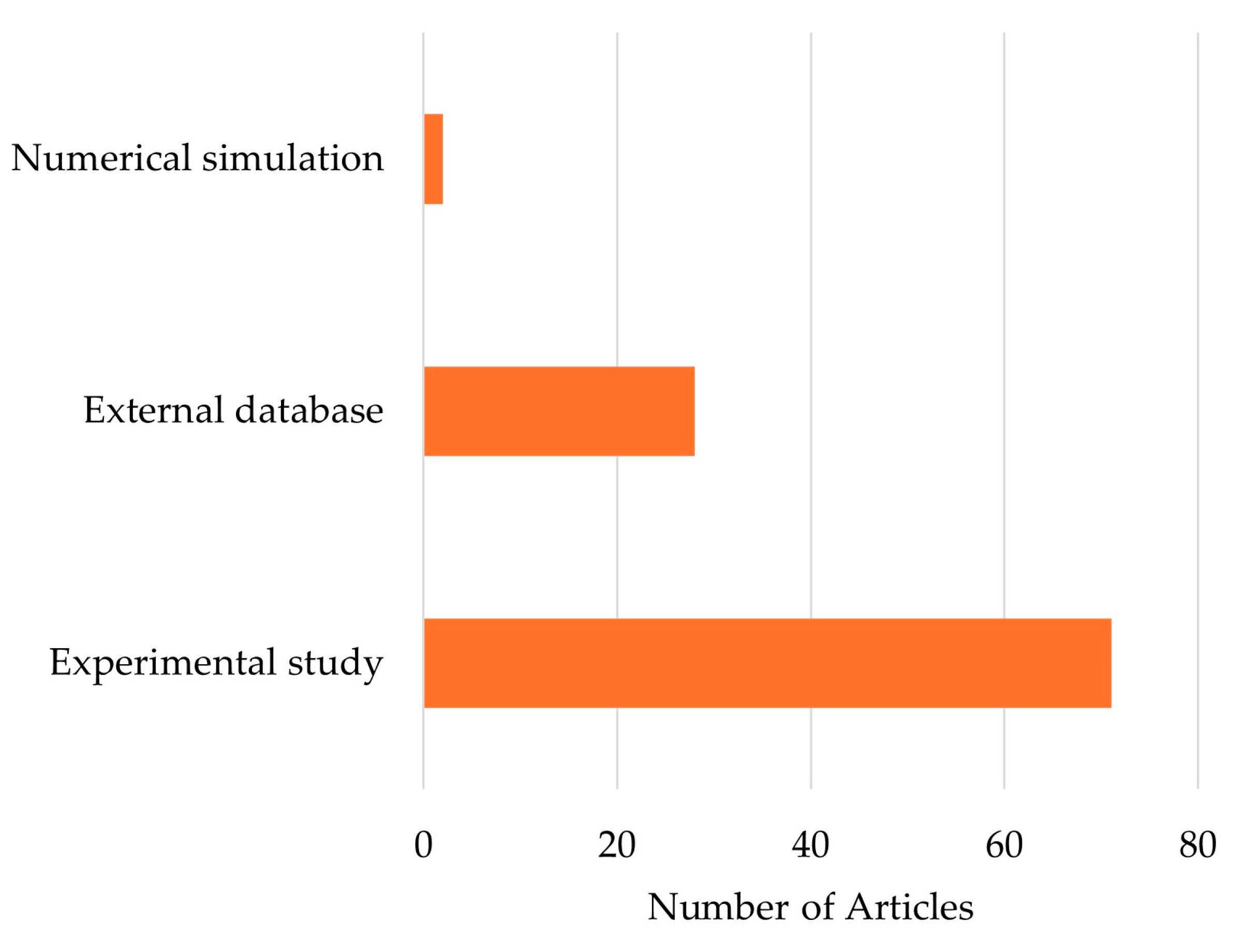
3.2. Research Approach
3.2.1. Data
3.2.2. HTC and PD Correlations
3.2.3. Test Conditions
3.3. Operating Conditions
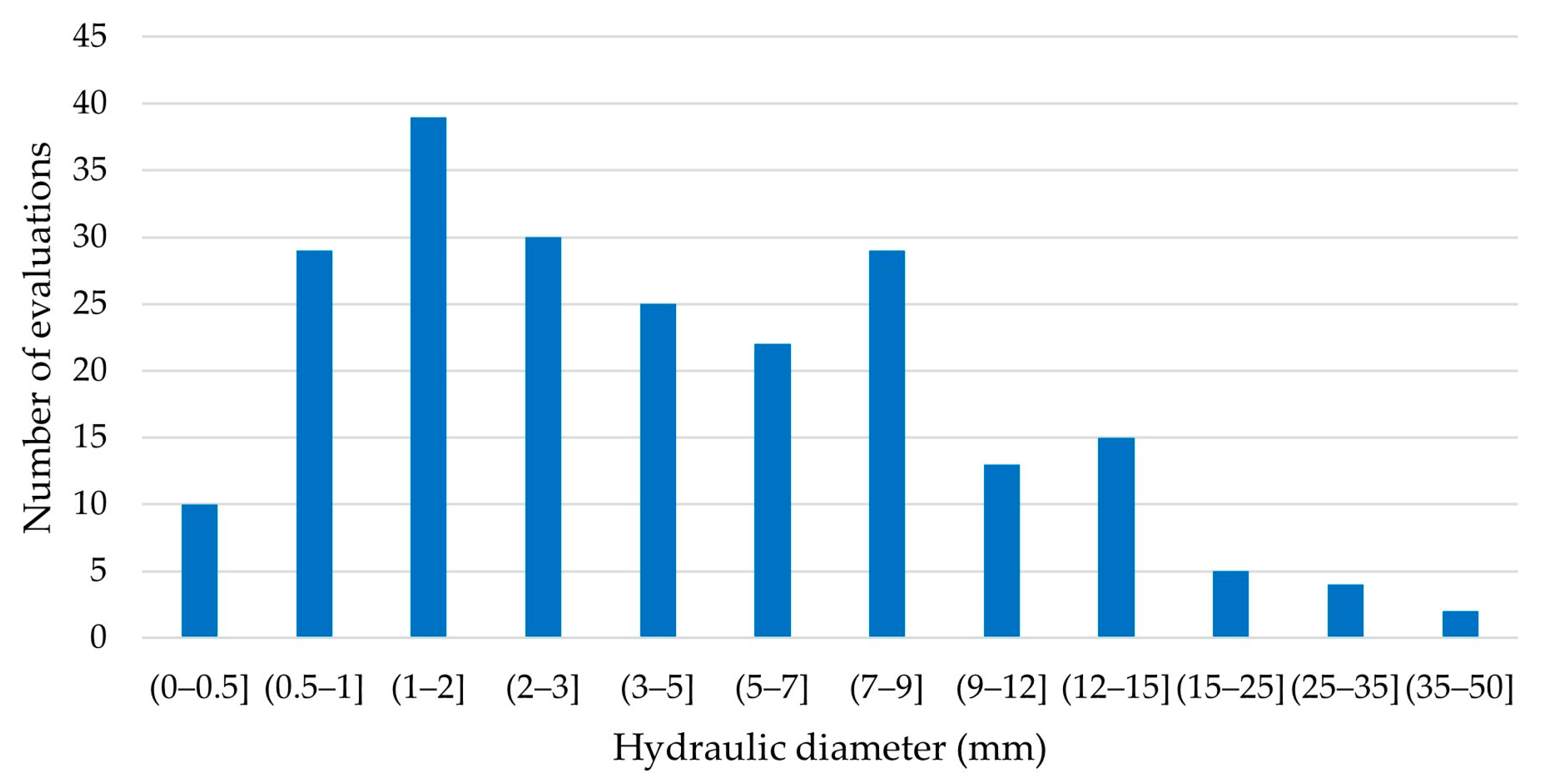
3.3.1. Hydraulic Diameters
3.3.2. Saturation Temperatures
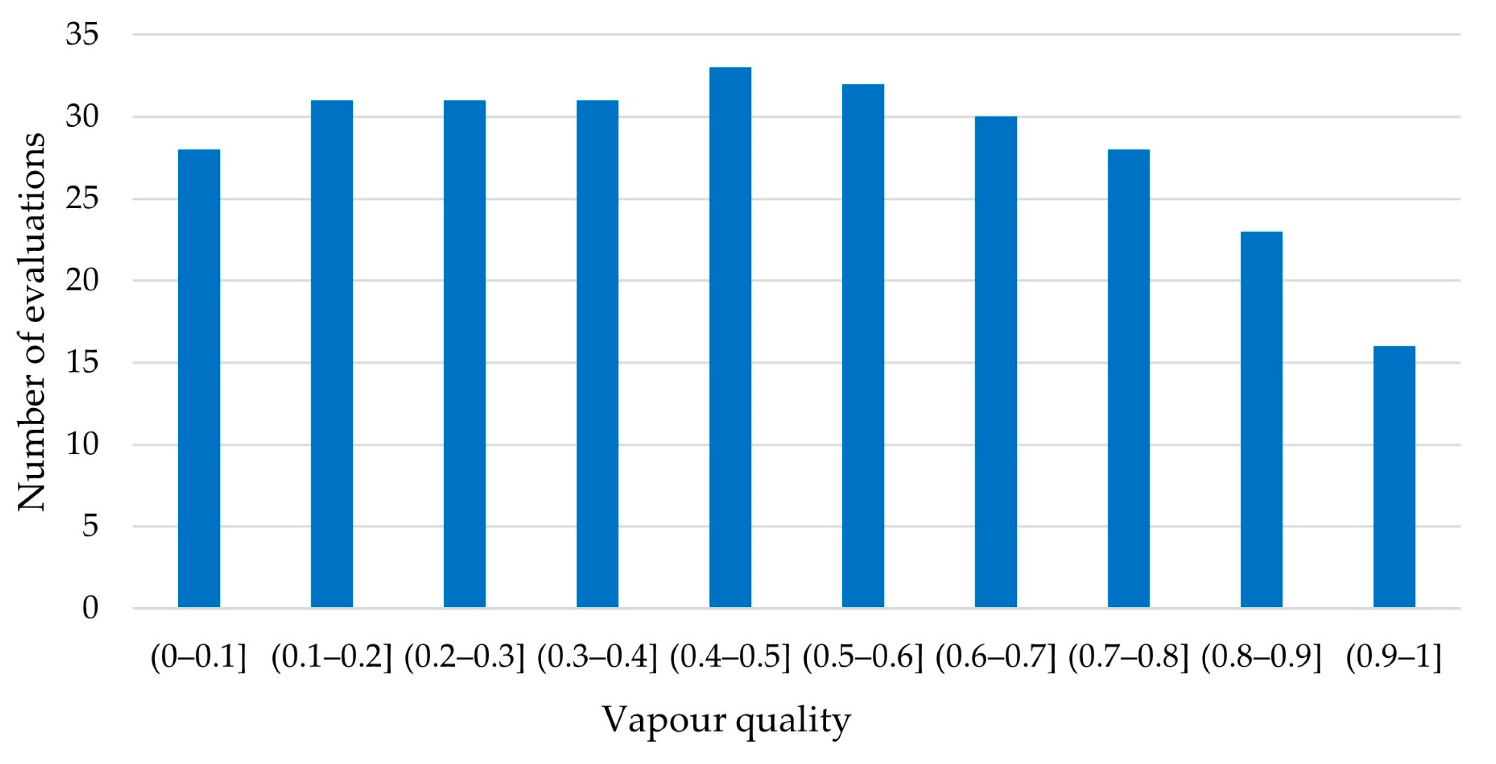
3.3.3. Vapour Quality
3.3.4. Specific Heat Flux
3.3.5. Specific Mass Flux
3.4. Refrigerants
Hydraulic Diameters and Saturation Temperatures
4. Correlations
4.1. R717
4.2. R1270
4.3. R600a
4.4. R290
5. Discussion
6. Conclusions
Author Contributions
Funding
Conflicts of Interest
Nomenclature
| Roman | |
| cp | Specific heat capacity [J/kgK] |
| d | Diameter [m] |
| g | Acceleration of gravity [m/s2] |
| G | Specific Mass flux [kg/m2s] |
| h | Heat transfer coefficient [W/m2K] |
| hlv | Latent heat of vaporization [J/kg] |
| i | Specific enthalpy [J/kg] |
| Jv | Vapour superficial velocity [m/s] |
| Lh | Heated length [m] |
| M | Molecular mass [kg/kmol] |
| N | Number of tube rows per meter |
| p | Pressure [Pa] |
| pr | Reduced pressure, |
| q | Specific Heat flux [W/m2] |
| Ra | Mean roughness height [µm] |
| Rx | Area enhancement [–] |
| SV | Specific volume, |
| T | Temperature [°C] |
| x | Vapour quality [–] |
| Greek letters | |
| β | Chevron angle [°] |
| β* | Reduced chevron angle [–] |
| δ | Channel height [m] |
| Δp | Pressure drop [Pa] |
| θ | Winding angle [°] |
| λ | Thermal conductivity [W/mK] |
| µ | Dynamic viscosity [Pa·s] |
| ν | Kinematic viscosity [m2/s] |
| ρ | Density [kg/m3] |
| ρ* | Density ratio, |
| ρtp | Two phase density, |
| σ | Surface tension [N/m] |
| Subscripts | |
| avg | Average |
| c | Critical |
| cb | Convective boiling |
| eq | Equivalent |
| exp | Experimental |
| flat | Flattened tubes |
| frict | Frictional |
| h | Hydraulic |
| i | Inner |
| l | Liquid |
| lf | Liquid film |
| lo | Liquid only |
| loc | Local |
| nb | Nucleate Boiling |
| o | Outer |
| pb | Pool boiling |
| pred | Predicted |
| sat | Saturation |
| v | Vapour |
| vo | Vapour only |
| w | Wall |
| Abbreviations | |
| AD | Average deviation |
| aPD | Adiabatic flow pressure drop |
| AAD | Absolute average deviation |
| CFCs | Chlorofluorocarbons |
| f.p.m. | Fins per meter |
| GWP | Global warming potential |
| HBHX | Helically baffled shell-and-tube heat exchanger |
| HCFCs | Hydrochlorofluorocarbons |
| HC Rs | Hydrocarbon refrigerants |
| HFCs | Hydrofluorocarbons |
| HFO | Hydrofluoroolefin |
| HT | Heat transfer |
| bHT | Boiling heat transfer |
| cHT | Condensation heat transfer |
| HTC | Heat transfer coefficient |
| LHP | Loop heat pipe |
| LNG | Liquefied natural gas |
| MF | Microfin |
| ODF | Offset strip fin |
| ODP | Ozone depletion potential |
| PCHE | Printed circuit heat exchanger |
| PD | Pressure drop |
| PHE | Plate heat exchanger |
| R | Refrigerant |
| ST | Smooth tube |
| SWHE | Spiral wound heat exchanger |
| TP | Two phase |
| TPCT | Two-phase closed thermosyphon |
| VQ | Vapour quality |
| Dimensionless numbers | |
| Bo | Boiling number, |
| Bd | Bond number, |
| Cn | Confinement number, |
| Co | Convection number, |
| Fa | Fang number, |
| Two-phase frictional multiplier (Chisholm), | |
| Frl | Liquid Froude number, |
| f | Friction factor ≡ Darcy factor, |
| fFann | Fanning friction factor, |
| Ja | Jacob’s number, |
| Ka | Kapitza number, |
| Nu | Nusselt number, |
| Pr | Prandtl number, |
| Reeq | Equivalent Raynolds number, |
| Rel | Liquid Reynolds number, |
| Rev | Vapour Reynolds number, |
| Reko | Liquid only (k = l) or vapor only (k = v) Re, |
| We | Weber number, |
| Xtt | Lockhart–Martinelli parameter, |
| (Turbulent–Turbulent flow) | |
| Xvv | Lockhart–Martinelli parameter, |
| (Laminar–Laminar flow) |
References
- Council of the European Union. Proposal for a Regulation of the European Parliament and of the Council on Fluorinated Greenhouse Gases, Amending Directive (EU) 2019/1937 and Repealing Regulation (EU) No 517/2014; European Commission: Brussels, Belgium, 2023; Available online: https://eur-lex.europa.eu/legal-content/EN/TXT/?uri=consil%3AST_14409_2023_INIT (accessed on 12 January 2024).
- Sunden, B.; Meyer, J.; Dirker, J.; John, B.; Mukkamala, Y. Local Measurements in Heat Exchangers: A Systematic Review and Regression Analysis. Heat Transf. Eng. 2021, 43, 1529–1565. [Google Scholar] [CrossRef]
- Cavallini, A.; Del Col, D.; Rossetto, L. Heat transfer and pressure drop of natural refrigerants in minichannels (low charge equipment). Int. J. Refrig. 2013, 36, 287–300. [Google Scholar] [CrossRef]
- Thome, J.; Cheng, L.; Ribatski, G.; Vales, L. Flow boiling of ammonia and hydrocarbons: A state-of-the-art review. Int. J. Refrig. 2008, 31, 603–620. [Google Scholar] [CrossRef]
- Liberati, A.; Altman, D.G.; Tetzlaff, J.; Mulrow, C.; Gøtzsche, P.C.; Ioannidis, J.P.A.; Clarke, M.; Devereaux, P.J.; Kleijnen, J.; Moher, D. The PRISMA statement for reporting systematic reviews and meta-analyses of studies that evaluate healthcare interventions: Explanation and elaboration. BMJ Clin. Res. Ed. 2009, 339, b2700. [Google Scholar] [CrossRef] [PubMed]
- Aǧra, O.; Teke, I. Determination of the heat transfer coefficient during annular flow condensation in smooth horizontal tubes. J. Therm. Sci. Technol. 2012, 32, 151–159. [Google Scholar]
- Ahmadpour, M.M.; Akhavan-Behabadi, M.A.; Sajadi, B.; Salehi-Kohestani, A. Effect of lubricating oil on condensation characteristics of R600a inside a horizontal U-shaped tube: Experimental study. Int. J. Therm. Sci. 2019, 145, 106007. [Google Scholar] [CrossRef]
- Akbar, R.; Oh, J.; Pamitran, A. Evaluation of Heat Transfer Coefficient of Two-Phase Flow Boiling with R290 in Horizontal Mini Channel. J. Adv. Res. Fluid Mech. Therm. Sci. 2021, 88, 88–95. [Google Scholar] [CrossRef]
- Ali, M.S.; Anwar, Z.; Mujtaba, M.A.; Khidmatgar, A.; Goodarzi, M. Two-phase frictional pressure drop with pure refrigerants in vertical mini/micro-channels. Case Stud. Therm. Eng. 2021, 23, 100824. [Google Scholar] [CrossRef]
- Allymehr, E.; Pardiñas, Á.; Eikevik, T.; Hafner, A. Characteristics of evaporation of propane (R290) in compact smooth and microfinned tubes. Appl. Therm. Eng. 2020, 181, 115880. [Google Scholar] [CrossRef]
- Allymehr, E.; Pardiñas, Á.; Eikevik, T.; Hafner, A. Comparative analysis of evaporation of Isobutane (R600a) and Propylene (R1270) in compact smooth and microfinned tubes. Appl. Therm. Eng. 2021, 188, 116606. [Google Scholar] [CrossRef]
- Allymehr, E.; Pardiñas, Á.; Eikevik, T.; Hafner, A. Condensation of Hydrocarbons in Compact Smooth and Microfinned Tubes. Energies 2021, 14, 2647. [Google Scholar] [CrossRef]
- Amalfi, R.L.; Vakili-Farahani, F.; Thome, J.R. Flow boiling and frictional pressure gradients in plate heat exchangers. Part 2: Comparison of literature methods to database and new prediction methods. Int. J. Refrig. 2016, 61, 185–203. [Google Scholar] [CrossRef]
- Amalfi, R.L.; Vakili-Farahani, F.; Thome, J.R. Flow boiling and frictional pressure gradients in plate heat exchangers. Part 1: Review and experimental database. Int. J. Refrig. 2016, 61, 166–184. [Google Scholar] [CrossRef]
- Anwar, Z.; Palm, B.; Khodabandeh, R. Flow Boiling Heat Transfer and Dryout Characteristics of R600a in a Vertical Minichannel. Exp. Therm. Fluid Sci. 2015, 36, 1230–1240. [Google Scholar] [CrossRef]
- Arima, H.; Kim, J.H.; Okamoto, A.; Ikegami, Y. Local boiling heat transfer characteristics of ammonia in a vertical plate evaporator. Int. J. Refrig. 2010, 33, 359–370. [Google Scholar] [CrossRef]
- Asim, M.; Anwar, Z.; Farooq, M.; Shaukat, R.; Imran, S.; Abbas, M.M.; Ali, Q. Flow boiling heat transfer characteristics of low GWP refrigerants in a vertical mini-channel. Therm. Sci. 2022, 26, 63–76. [Google Scholar] [CrossRef]
- Ayub, Z.H.; Khan, T.S.; Salam, S.; Nawaz, K.; Ayub, A.H.; Khan, M.S. Literature Survey and a Universal Evaporation Correlation for Plate type Heat Exchangers. Int. J. Refrig. 2019, 99, 408–418. [Google Scholar] [CrossRef]
- Başaran, A.; Benim, A.C.; Yurddas, A. Numerical Simulation of the Condensation Flow of the Isobutane (R600a) inside Microchannel. Heat Transf. Eng. 2021, 43, 337–361. [Google Scholar] [CrossRef]
- Başaran, A.; Yurddaş, A. Thermal modeling and designing of microchannel condenser for refrigeration applications operating with isobutane (R600a). Appl. Therm. Eng. 2021, 198, 117446. [Google Scholar] [CrossRef]
- Butrymowicz, D.; Śmierciew, K.; Karwacki, J.; Borsukiewicz, A.; Gagan, J. Experimental Investigations of Flow Boiling Heat Transfer under Near-Critical Pressure for Selected Working Fluids. Sustainability 2022, 14, 14029. [Google Scholar] [CrossRef]
- Butrymowicz, D.; Śmierciew, K.; Gagan, J.; Dudar, A.; Lukaszuk, M.; Zou, H.; Łapiński, A. Investigations of Performance of Mini-Channel Condensers and Evaporators for Propane. Sustainability 2022, 14, 14249. [Google Scholar] [CrossRef]
- Cao, X.; Wang, X.; Song, Q.; Wang, D.; Li, Y. Experimental investigation on the heat transfer and pressure drop characteristics of R600a in a minichannel condenser with different inclined angles. Appl. Therm. Eng. 2021, 196, 117227. [Google Scholar] [CrossRef]
- Choi, K.-I.; Pamitran, A.S.; Oh, J.-T.; Saito, K. Pressure drop and heat transfer during two-phase flow vaporization of propane in horizontal smooth minichannels. Int. J. Refrig. 2009, 32, 837–845. [Google Scholar] [CrossRef]
- Choi, K.-I.; Oh, J.-T.; Saito, K.; Jeong, J. Comparison of heat transfer coefficient during evaporation of natural refrigerants and R-1234yf in horizontal small tube. Int. J. Refrig. 2014, 41, 210–218. [Google Scholar] [CrossRef]
- Cioncolini, A.; Thome, J.R. Algebraic turbulence modeling in adiabatic and evaporating annular two-phase flow. Int. J. Heat Fluid Flow 2011, 32, 805–817. [Google Scholar] [CrossRef]
- Da Silva, P.F.; de Oliveira, J.D.; Copetti, J.B.; Macagnan, M.; Cardoso, E. Flow boiling pressure drop and flow patterns of R-600a in a multiport minichannels. Int. J. Refrig. 2023, 148, 13–24. [Google Scholar] [CrossRef]
- Da Silva Lima, R.J.; Quibén, J.M.; Kuhn, C.; Boyman, T.; Thome, J.R. Ammonia two-phase flow in a horizontal smooth tube: Flow pattern observations, diabatic and adiabatic frictional pressure drops and assessment of prediction methods. Int. J. Heat Mass Transf. 2009, 52, 2273–2288. [Google Scholar] [CrossRef]
- Dalkilic, A.S.; Ağra, Ö.; Teke, I.; Wongwises, S. Comparison of frictional pressure drop models during annular flow condensation of R600a in a horizontal tube at low mass flux and of R134a in a vertical tube at high mass flux. Int. J. Heat Mass Transf. 2010, 53, 2052–2064. [Google Scholar] [CrossRef]
- Darzi, M.; Akhavan-Behabadi, M.A.; Sadoughi, M.K.; Razi, P. Experimental study of horizontal flattened tubes performance on condensation of R600a vapor. Int. Commun. Heat Mass Transf. 2015, 62, 18–25. [Google Scholar] [CrossRef]
- De Oliveira, J.D.; Biancon Copetti, J.; Passos, J.C. An experimental investigation on flow boiling heat transfer of R-600a in a horizontal small tube. Int. J. Refrig. 2016, 72, 97–110. [Google Scholar] [CrossRef]
- De Oliveira, J.D.; Biancon Copetti, J.; Passos, J.C. Experimental investigation on flow boiling pressure drop of R-290 and R-600a in a horizontal small tube. Int. J. Refrig. 2017, 84, 165–180. [Google Scholar] [CrossRef]
- De Oliveira, J.D.; Passos, J.C.; Biancon Copetti, J.; Van der Geld, C.W.M. Flow boiling heat transfer of propane in 1.0 mm tube. Exp. Therm. Fluid Sci. 2018, 96, 243–256. [Google Scholar] [CrossRef]
- De Oliveira, J.D.; Passos, J.C.; Biancon Copetti, J.; Van der Geld, C.W.M. On flow boiling of R-1270 in a small horizontal tube: Flow patterns and heat transfer. Appl. Therm. Eng. 2020, 178, 115403. [Google Scholar] [CrossRef]
- De Oliveira, J.D.; Passos, J.C.; Biancon Copetti, J.; Cardoso, E.M.; de Souza, R.R. Flow boiling pressure drop of R-1270 in 1.0 mm tube. Appl. Therm. Eng. 2023, 231, 120885. [Google Scholar] [CrossRef]
- Del Col, D.; Bortolato, M.; Bortolin, S. Comprehensive experimental investigation of two-phase heat transfer and pressure drop with propane in a minichannel. Int. J. Refrig. 2014, 47, 66–84. [Google Scholar] [CrossRef]
- Del Col, D.; Azzolin, M.; Bortolin, S.; Berto, A. Experimental results and design procedures for minichannel condensers and evaporators using propylene. Int. J. Refrig. 2017, 83, 23–38. [Google Scholar] [CrossRef]
- Elfaham, M.; Tang, C. A Comparative Analysis of Two-Phase Flow Boiling Heat Transfer Coefficient and Correlations for Hydrocarbons and Ethanol. Energies 2023, 16, 5931. [Google Scholar] [CrossRef]
- Fang, X.; Zhuang, F.; Chen, C.; Wu, Q.; Chen, Y.; Chen, Y.; He, Y. Saturated flow boiling heat transfer: Review and assessment of prediction methods. Heat Mass Transf. 2019, 55, 197–222. [Google Scholar] [CrossRef]
- Fang, X.; Qiu, G.; Che, X.; Chen, J.; Cai, W. Evaluation of prediction models on frictional pressure drop for condensation flow in horizontal circular tubes. Energy Sources A Recovery Util. Environ. Eff. 2023, 45, 6305–6316. [Google Scholar] [CrossRef]
- Moghaddam, H.A.; Sarmadian, A.; Shafaee, M.; Enayatollahi, H. Flow pattern maps, pressure drop and performance assessment of horizontal tubes with coiled wire inserts during condensation of R-600a. Int. J. Heat Mass Transf. 2020, 148, 119062. [Google Scholar] [CrossRef]
- Fries, S.; Skusa, S.; Luke, A. Heat transfer and pressure drop of condensation of hydrocarbons in tubes. Heat Mass Transf. 2019, 55, 33–40. [Google Scholar] [CrossRef]
- Fries, S.; Deeb, M.; Luke, A. Influence of Surface Roughness on Pressure Drop in Two-Phase Flow of Saturated Hydrocarbons. Chem. Ing. Tech. 2020, 92, 608–612. [Google Scholar] [CrossRef]
- Fronk, B.; Garimella, S. Condensation of ammonia and high-temperature-glide zeotropic ammonia/water mixtures in minichannels—Part II: Heat transfer models. Int. J. Heat Mass Transf. 2016, 101, 1357–1373. [Google Scholar] [CrossRef]
- Fronk, B.; Garimella, S. Condensation of ammonia and high-temperature-glide ammonia/water zeotropic mixtures in minichannels—Part I: Measurements. Int. J. Heat Mass Transf. 2016, 101, 1343–1356. [Google Scholar] [CrossRef]
- Gao, Y.; Shao, S.; Zhan, B.; Chen, Y.; Tian, C. Heat transfer and pressure drop characteristics of ammonia during flow boiling inside a horizontal small diameter tube. Int. J. Heat Mass Transf. 2018, 127, 981–996. [Google Scholar] [CrossRef]
- Gao, Y.; Feng, Y.; Shao, S.; Tian, C. Two-phase pressure drop of ammonia in horizontal small diameter tubes: Experiments and correlation. Int. J. Refrig. 2019, 98, 283–293. [Google Scholar] [CrossRef]
- Ghazali, M.A.H.; Mohd-Yunos, Y.; Pamitran, A.S.; Jong-Taek, O.; Mohd-Ghazali, N. Development of a new correlation for pre-dry out evaporative heat transfer coefficient of R290 in a microchannel. Int. J. Air-Cond. Refrig. 2022, 30, 15. [Google Scholar] [CrossRef]
- Ghorbani, B.; Akhavan-Behabadi, M.A.; Ebrahimi, S.; Vijayaraghavan, K. Experimental investigation of condensation heat transfer of R600a/POE/CuO nano-refrigerant in flattened tubes. Int. Commun. Heat Mass Transf. 2017, 88, 236–244. [Google Scholar] [CrossRef]
- Guo, Q.; Li, M.; Gu, H. Condensation heat transfer characteristics of low-GWP refrigerants in a smooth horizontal mini tube. Int. J. Heat Mass Transf. 2018, 126, 26–38. [Google Scholar] [CrossRef]
- Huang, J.; Sheer, T.; Bailey-McEwan, M. Heat transfer and pressure drop in plate heat exchanger refrigerant evaporators. Int. J. Refrig. 2012, 35, 325–335. [Google Scholar] [CrossRef]
- Huang, J.; Bailey-McEwan, M.; Sheer, T. Performance Analysis of Plate Heat Exchangers used as Refrigerant Evaporators. In Proceedings of the 22nd International Congress of Refrigeration, Beijing, China, 21–26 August 2007. [Google Scholar]
- Ilie, A.; Girip, A.; Calotă, R.; Călin, A. Investigation on the Ammonia Boiling Heat Transfer Coefficient in Plate Heat Exchangers. Energies 2022, 15, 1503. [Google Scholar] [CrossRef]
- Inoue, N.; Hirose, M.; Jige, D.; Ichinose, J. Correlation for Condensation Heat Transfer in a 4.0 mm Smooth Tube and Relationship with R1234ze(E), R404A, and R290. Appl. Sci. 2018, 8, 2267. [Google Scholar] [CrossRef]
- Kanizawa, F.T.; Tibiriçá, C.B.; Ribatski, G. Heat transfer during convective boiling inside microchannels. Int. J. Heat Mass Transf. 2016, 93, 566–583. [Google Scholar] [CrossRef]
- Khan, T.S.; Khan, M.S.; Chyu, M.-C.; Ayub, Z.H. Experimental investigation of evaporation heat transfer and pressure drop of ammonia in a 60° chevron plate heat exchanger. Int. J. Refrig. 2012, 35, 336–348. [Google Scholar] [CrossRef]
- Khan, M.S.; Khan, T.S.; Chyu, M.-C.; Ayub, Z.H. Experimental investigation of evaporation heat transfer and pressure drop of ammonia in a 30° chevron plate heat exchanger. Int. J. Refrig. 2012, 35, 1757–1765. [Google Scholar] [CrossRef]
- Koyama, K.; Chiyoda, H.; Arima, H.; Ikegami, Y. Experimental study on thermal characteristics of ammonia flow boiling in a plate evaporator at low mass flux. Int. J. Refrig. 2014, 38, 227–235. [Google Scholar] [CrossRef]
- Lee, H.-S.; Son, C.-H. Condensation heat transfer and pressure drop characteristics of R-290, R-600a, R-134a and R-22 in horizontal tubes. Heat Mass Transf. 2010, 46, 571–584. [Google Scholar] [CrossRef]
- Lillo, G.; Mastrullo, R.; Mauro, A.W.; Viscito, L. Flow boiling heat transfer, dry-out vapor quality and pressure drop of propane (R290): Experiments and assessment of predictive methods. Int. J. Heat Mass Transf. 2018, 126, 1236–1252. [Google Scholar] [CrossRef]
- Liu, N.; Xiao, H.; Li, J. Experimental investigation of condensation heat transfer and pressure drop of propane, R1234ze(E) and R22 in minichannels. Appl. Therm. Eng. 2016, 102, 63–72. [Google Scholar] [CrossRef]
- Liu, J.; Liu, J.; Li, R.; Xu, X. Experimental study on flow boiling characteristics in a high aspect ratio vertical rectangular mini-channel under low heat and mass flux. Exp. Therm. Fluid Sci. 2018, 98, 146–157. [Google Scholar] [CrossRef]
- Longo, G.A. Hydrocarbon Refrigerant Vaporization Inside a Brazed Plate Heat Exchanger. J. Heat Transf. 2012, 134, 101801. [Google Scholar] [CrossRef]
- Longo, G.A.; Mancin, S.; Righetti, G.; Zilio, C. Saturated vapour condensation of HFC404A inside a 4 mm ID horizontal smooth tube: Comparison with the long-term low GWP substitutes HC290 (Propane) and HC1270 (Propylene). Int. J. Heat Mass Transf. 2017, 108, 2088–2099. [Google Scholar] [CrossRef]
- Longo, G.A.; Mancin, S.; Righetti, G.; Zilio, C. Flow boiling heat transfer capabilities of R134a low GWP substitutes inside a 4 mm id horizontal smooth tube: R600a and R152a. Heat Mass Transf. 2020, 1–19. [Google Scholar] [CrossRef]
- Longo, G.A.; Mancin, S.; Righetti, G.; Zilio, C. Hydrocarbon refrigerants boiling local heat transfer coefficients inside a Brazed Plate Heat Exchanger (BPHE). Int. J. Refrig. 2023, 156, 113–122. [Google Scholar] [CrossRef]
- Lopez-Belchi, A.; Illán-Gómez, F.; García-Cascales, J.R.; Vera-García, F. Condensing two-phase pressure drop and heat transfer coefficient of propane in a horizontal multiport mini-channel tube: Experimental measurements. Int. J. Refrig. 2016, 68, 59–75. [Google Scholar] [CrossRef]
- Macdonald, M.; Garimella, S. Hydrocarbon condensation in horizontal smooth tubes: Part I—Measurements. Int. J. Heat Mass Transf. 2016, 93, 75–85. [Google Scholar] [CrossRef]
- Macdonald, M.; Garimella, S. Hydrocarbon condensation in horizontal smooth tubes: Part II—Heat transfer coefficient and pressure drop modeling. Int. J. Heat Mass Transf. 2016, 93, 1248–1261. [Google Scholar] [CrossRef]
- Macdonald, M.; Garimella, S. Effect of Temperature Difference on In-Tube Condensation Heat Transfer Coefficients. J. Heat Transf. 2017, 139, 2546597. [Google Scholar] [CrossRef]
- Maher, D.; Hana, A.; Habib, S. New Correlations for Two Phase Flow Pressure Drop in Homogeneous Flows Model. Therm. Eng. 2020, 67, 92–105. [Google Scholar] [CrossRef]
- Maqbool, M.H.; Palm, B.; Khodabandeh, R. Flow boiling of ammonia in vertical small diameter tubes: Two phase frictional pressure drop results and assessment of prediction methods. Int. J. Therm. Sci. 2012, 54, 1–12. [Google Scholar] [CrossRef]
- Maqbool, M.H.; Palm, B.; Khodabandeh, R. Boiling heat transfer of ammonia in vertical smooth mini channels: Experimental results and predictions. Int. J. Therm. Sci. 2012, 54, 13–21. [Google Scholar] [CrossRef]
- Maqbool, M.H.; Palm, B.; Khodabandeh, R. Investigation of two phase heat transfer and pressure drop of propane in a vertical circular minichannel. Exp. Therm. Fluid Sci. 2013, 46, 120–130. [Google Scholar] [CrossRef]
- Mohd-Yunos, Y.; Mohd-Ghazali, N.; Mohamad, M.; Pamitran, A.S.; Oh, J.-T. Improvement of two-phase heat transfer correlation superposition type for propane by genetic algorithm. Heat Mass Transf. 2020, 56, 1087–1098. [Google Scholar] [CrossRef]
- Moreira, T.A.; Ayub, Z.H.; Ribatski, G. Convective condensation of R600a, R290, R1270 and their zeotropic binary mixtures in horizontal tubes. Int. J. Refrig. 2021, 130, 27–43. [Google Scholar] [CrossRef]
- Morrow, J.A.; Huber, R.A.; Nawaz, K.; Derby, M.M. Flow condensation heat transfer performance of natural and emerging synthetic refrigerants. Int. J. Refrig. 2021, 132, 293–321. [Google Scholar] [CrossRef]
- Murphy, D.L.; Macdonald, M.P.; Mahvi, A.J.; Garimella, S. Condensation of propane in vertical minichannels. Int. J. Heat Mass Transf. 2019, 137, 1154–1166. [Google Scholar] [CrossRef]
- Nasr, M.; Akhavan-Behabadi, M.A.; Momenifar, M.R.; Hanafizadeh, P. Heat transfer characteristic of R-600a during flow boiling inside horizontal plain tube. Int. Commun. Heat Mass Transf. 2015, 66, 93–99. [Google Scholar] [CrossRef]
- Oh, J.-T.; Pamitran, A.S.; Choi, K.-I.; Hrnjak, P. Experimental investigation on two-phase flow boiling heat transfer of five refrigerants in horizontal small tubes of 0.5, 1.5 and 3.0 mm inner diameters. Int. J. Heat Mass Transf. 2011, 54, 2080–2088. [Google Scholar] [CrossRef]
- Pamitran, A.S.; Choi, K.-I.; Oh, J.-T.; Park, K.-W. Two-phase flow heat transfer of propane vaporization in horizontal minichannels. J. Mech. Sci. Tech. 2009, 23, 599–606. [Google Scholar] [CrossRef]
- Pamitran, A.S.; Choi, K.-I.; Oh, J.-T.; Nasruddin, N. Evaporation heat transfer coefficient in single circular small tubes for flow natural refrigerants of C3H8, NH3, and CO2. Int. J. Multiph. Flow 2011, 37, 794–801. [Google Scholar] [CrossRef]
- Patel, T.; Parekh, A.; Tailor, P. Theoretical analysis of two-phase frictional pressure drop during condensing in horizontal mini channel. Int. J. Mech. Eng. Tech. 2018, 9, 61–71. [Google Scholar]
- Pham, Q.V.; Choi, K.-I.; Oh, J.-T. Condensation Heat Transfer Characteristics and Pressure Drops of R410A, R22, R32, and R290 in Multiport Rectangular Channel. Sci. Technol. Built. Environ. 2019, 25, 1325–1336. [Google Scholar] [CrossRef]
- Qiu, J.; Zhang, H.; Yu, X.; Qi, Y.; Lou, J.; Wang, X. Experimental investigation of flow boiling heat transfer and pressure drops characteristic of R1234ze(E), R600a, and a mixture of R1234ze(E)/R32 in a horizontal smooth tube. Adv. Mech. Eng. 2015, 7, 1687814015606311. [Google Scholar] [CrossRef]
- Sempértegui Tapia, D.F.; Ribatski, G. Flow boiling heat transfer of R134a and low GWP refrigerants in a horizontal micro-scale channel. Int. J. Heat Mass Transf. 2017, 108, 2417–2432. [Google Scholar] [CrossRef]
- Sempértegui Tapia, D.F.; Ribatski, G. Two-phase frictional pressure drop in horizontal micro-scale channels: Experimental data analysis and prediction method development. Int. J. Refrig. 2017, 79, 143–163. [Google Scholar] [CrossRef]
- Shafaee, M.; Alimardani, F.; Mohseni, S.G. An empirical study on evaporation heat transfer characteristics and flow pattern visualization in tubes with coiled wire inserts. Int. Commun. Heat Mass Transf. 2016, 76, 301–307. [Google Scholar] [CrossRef]
- Shah, M.M. An Improved and Extended General Correlation for Heat Transfer During Condensation in Plain Tubes. HVAC&R Res. 2009, 15, 889–913. [Google Scholar]
- Shah, M.M. A correlation for heat transfer during condensation in horizontal mini/micro channels. Int. J. Refrig. 2016, 64, 187–202. [Google Scholar] [CrossRef]
- Shah, M.M. Unified correlation for heat transfer during boiling in plain mini/micro and conventional channels. Int. J. Refrig. 2016, 74, 606–626. [Google Scholar] [CrossRef]
- Shah, M.M. Comprehensive correlation for dispersed flow film boiling heat transfer in mini/macro tubes. Int. J. Refrig. 2017, 78, 32–46. [Google Scholar] [CrossRef]
- Shah, M.M. Heat transfer during condensation in corrugated plate heat exchangers. Int. J. Refrig. 2021, 127, 180–193. [Google Scholar] [CrossRef]
- Shah, M.M. New general correlation for heat transfer during saturated boiling in mini and macro channels. Int. J. Refrig. 2022, 137, 103–116. [Google Scholar] [CrossRef]
- Tao, X.; Infante Ferreira, C.A. Heat transfer and frictional pressure drop during condensation in plate heat exchangers: Assessment of correlations and a new method. Int. J. Heat Mass Transf. 2019, 135, 996–1012. [Google Scholar] [CrossRef]
- Tao, X.; Infante Ferreira, C.A. NH3 condensation in a plate heat exchanger: Flow pattern based models of heat transfer and frictional pressure drop. Int. J. Heat Mass Transf. 2020, 154, 119774. [Google Scholar] [CrossRef]
- Tao, X.; Dahlgren, E.; Leichsenring, M.; Infante Ferreira, C.A. NH3 condensation in a plate heat exchanger: Experimental investigation on flow patterns, heat transfer and frictional pressure drop. Int. J. Heat Mass Transf. 2020, 151, 119374. [Google Scholar] [CrossRef]
- Turgut, O.E.; Coban, M.T.; Asker, M. Comparison of flow boiling pressure drop correlations for smooth macrotubes. Heat Transf. Eng. 2016, 37, 487–506. [Google Scholar] [CrossRef]
- Turgut, O.E.; Coban, M.T. A New Saturated Two-Phase Flow Boiling Correlation Based on Propane (R290) Data. Arab. J. Sci. Eng. 2021, 46, 7851–7874. [Google Scholar] [CrossRef]
- Turgut, O.E.; Genceli, H.; Asker, M.; Coban, M.T. Novel Saturated Flow Boiling Correlations for R600a and R717 Refrigerants. Heat Transf. Eng. 2022, 43, 1579–1609. [Google Scholar] [CrossRef]
- Umar, F.; Oh, J.T.; Pamitran, A.S. Evaluation of Pressure Drop of Two-Phase Flow Boiling with R290 in Horizontal Mini Channel. J. Adv. Res. Fluid Mech. Therm. Sci. 2022, 89, 160–166. [Google Scholar] [CrossRef]
- Wang, S.; Gong, M.Q.; Chen, G.F.; Sun, Z.H.; Wu, J.F. Two-phase heat transfer and pressure drop of propane during saturated flow boiling inside a horizontal tube. Int. J. Refrig. 2014, 41, 200–209. [Google Scholar] [CrossRef]
- Wang, H.; Fang, X. Evaluation Analysis of Correlations of Flow Boiling Heat Transfer Coefficients Applied to Ammonia. Heat Transf. Eng. 2016, 37, 32–44. [Google Scholar] [CrossRef]
- Wen, J.; Gu, X.; Wang, S.; Li, Y.; Tu, J. The comparison of condensation heat transfer and frictional pressure drop of R1234ze(E), Propane and R134a in a horizontal mini-channel. Int. J. Refrig. 2018, 92, 208–224. [Google Scholar] [CrossRef]
- Yang, Z.; Gong, M.; Chen, G.; Zou, X.; Shen, J. Two-phase flow patterns, heat transfer and pressure drop characteristics of R600a during flow boiling inside a horizontal tube. Appl. Therm. Eng. 2017, 120, 654–671. [Google Scholar] [CrossRef]
- Yuan, S.; Cheng, W.-L.; Nian, Y.-L.; Zhong, Q.; Fan, Y.-F.; He, J. Evaluation of prediction methods for heat transfer coefficient of annular flow and a novel correlation. Appl. Therm. Eng. 2017, 114, 10–23. [Google Scholar] [CrossRef]
- Zhang, Y.; Tan, H.; Li, Y.; Shan, S.; Liu, Y. A modified heat transfer correlation for flow boiling in small channels based on the boundary layer theory. Int. J. Heat Mass Transf. 2019, 132, 107–117. [Google Scholar] [CrossRef]
- Zhang, J.; Elmegaard, B.; Haglind, F. Condensation heat transfer and pressure drop correlations in plate heat exchangers for heat pump and organic Rankine cycle systems. Appl. Therm. Eng. 2021, 183, 116231. [Google Scholar] [CrossRef]
- Zhang, J.; Haglind, F. Experimental analysis of high temperature flow boiling heat transfer and pressure drop in a plate heat exchanger. Appl. Therm. Eng. 2021, 196, 117269. [Google Scholar] [CrossRef]
- Zhang, R.; Liu, J.; Zhang, L. Boiling Heat Transfer and Visualization for R717 in a Horizontal Smooth Mini-tube. Int. J. Refrig. 2021, 131, 275–285. [Google Scholar] [CrossRef]
- Zhang, R.; Liu, J.; Zhang, L. Flow boiling heat transfer and dryout characteristics of ammonia in a horizontal smooth mini-tube. Int. J. Therm. Sci. 2022, 171, 107224. [Google Scholar] [CrossRef]
- Cavallini, A.; Zecchin, R. A dimensionless correlation for heat transfer in forced convection condensation. In Proceedings of the 5th International Heat Transfer Conference Digital Library, Tokyo, Japan, 3–7 September 1974. [Google Scholar]
- Shah, M.M. A general correlation for heat transfer during film condensation inside pipes. Int. J. Heat Mass Transf. 1979, 22, 547–556. [Google Scholar] [CrossRef]
- Traviss, D.P.; Rohsenow, W.M.; Baron, A.B. Forced convection condensation inside tubes: A heat transfer equation for condenser design. ASHRAE Transact. 1973, 79, 157–165. [Google Scholar]
- Aizuddin, N.; Mohd-Ghazali, N.; Yushazaziah, M.-Y. Analysis of Convective Boiling Heat Transfer Coefficient Correlation of R290. J. Mech. 2018, 41, 39–44. [Google Scholar]
- Cavallini, A.; Del Col, D.; Matkovic, M.; Rossetto, L. Frictional pressure drop during vapour–liquid flow in minichannels: Modelling and experimental evaluation. Int. J. Heat Fluid Flow 2009, 30, 131–139. [Google Scholar] [CrossRef]
- Liu, Z.; Winterton, R.H. A general correlation for saturated and subcooled flow boiling in tubes and annuli, based on a nucleate pool boiling equation. Int. J. Heat Mass Transf. 1991, 34, 2759–2766. [Google Scholar] [CrossRef]
- Rollmann, P.; Spindler, K. New models for heat transfer and pressure drop during flow boiling of R407C and R410A in a horizontal microfin tube. Int. J. Therm. Sci. 2016, 103, 57–66. [Google Scholar] [CrossRef]
- Xu, Y.; Fang, X. A new correlation of two-phase frictional pressure drop for evaporating flow in pipes. Int. J. Refrig. 2012, 5, 2039–2050. [Google Scholar] [CrossRef]
- Diani, A.; Mancin, S.; Rossetto, L. R1234ze(E) flow boiling inside a 3.4 mm ID microfin tube. Int. J. Refrig. 2014, 47, 105–119. [Google Scholar] [CrossRef]
- Shah, M.M. Chart correlation for saturation boiling heat transfer: Equation and further study. ASHREA Trans. 1982, 88, 186–196. [Google Scholar]
- Dorao, C.A.; Fernandino, M. Simple and general correlation for heat transfer during flow condensation inside plain pipes. Int. J. Heat Mass Transf. 2018, 122, 290–305. [Google Scholar] [CrossRef]
- Cavallini, A.; Del Col, D.; Mancin, S.; Rossetto, L. Condensation of pure and near-azeotropic refrigerants in microfin tubes: A new computational procedure. Int. J. Refrig. 2009, 32, 162–174. [Google Scholar] [CrossRef]
- Xu, Y.; Fang, X. A new correlation of two-phase frictional pressure drop for condensing flow in pipes. Nucl. Eng. Des. 2013, 263, 87–96. [Google Scholar] [CrossRef]
- Li, W.; Wu, Z. A General Correlation for Evaporative Heat Transfer in Micro/Mini-Channels. Int. J. Heat Mass Transf. 2010, 53, 1778–1787. [Google Scholar] [CrossRef]
- Mahmoud, M.; Karayiannis, T. A Statistical Correlation for Flow Boiling Heat Transfer in Micro Tubes, In Proceedings of the 3rd European Conference on Microfluidics-Microfluidics, Heidelberg, Germany, 3–5 December 2012.
- Sakamatapan, K.; Wongwises, S. Pressure drop during condensation of R134a flowing inside a multiport minichannel. Int. J. Heat Mass Transf. 2014, 75, 31–39. [Google Scholar] [CrossRef]
- Gungor, K.E.; Wintertone, R.H.S. A general correlation for flow boiling in tubes and annuli. Int. J. Heat Mass Transf. 1986, 29, 351–358. [Google Scholar] [CrossRef]
- Müller-Steinhagen, H.; Heck, K. A simple friction pressure drop correlation for two-phase flow in pipes. Chem. Eng. Process. Process Intensif. 1986, 20, 297–308. [Google Scholar] [CrossRef]
- Hwang, Y.W.; Kim, M.S. The pressure drop in microtubes and the correlation development. Int. J. Heat Mass Transf. 2006, 49, 1804–1812. [Google Scholar] [CrossRef]
- Moreno Quibén, J.; Thome, J.R. Flow pattern based two-phase frictional pressure drop model for horizontal tubes. Part II: New phenomenological model. Int. J. Heat Fluid Flow 2007, 28, 1060–1072. [Google Scholar] [CrossRef]
- Chen, I.Y.; Yang, K.S.; Chang, Y.J.; Wang, C.C. Two-phase pressure drop of air– water and R-410a in small horizontal tubes. Int. J. Multiph. Flow 2001, 27, 1293–1299. [Google Scholar] [CrossRef]
- Mishima, K.; Hibiki, T. Some characteristics of air–water two-phase flow in small diameter vertical tubes. Int. J. Multiph. Flow 1996, 22, 703–712. [Google Scholar] [CrossRef]
- Jung, D.; Radermacher, R. Prediction of pressure drop during horizontal annular flow boiling of pure and mixed refrigerants, Int. J. Heat Mass Transf. 1989, 32, 2435–2446. [Google Scholar] [CrossRef]
- Kim, S.-M.; Mudawar, I. Universal approach to predicting saturated flow boiling heat transfer in mini/micro-channels—Part II. Two-phase heat transfer coefficient. Int. J. Heat Mass Transf. 2013, 64, 1239–1256. [Google Scholar] [CrossRef]
- Zhang, W.; Hibiki, T.; Mishima, K. Correlations of two-phase frictional pressure drop and void fraction in mini-channel. Int. J. Heat Mass Transf. 2010, 53, 453–465. [Google Scholar] [CrossRef]
- Bertsch, S.S.; Groll, E.A.; Garimella, S.V. A composite heat transfer correlation for saturated flow boiling in small channels. Int. J. Heat Mass Transf. 2009, 52, 2110–2118. [Google Scholar] [CrossRef]
- Moser, K.; Webb, R.; Na, B. A new equivalent Reynolds number model for condensation in smooth tubes. J. Heat Transf. 1998, 120, 410–417. [Google Scholar] [CrossRef]
- Thome, J.R.; Dupont, V.; Jacobi, A.M. Heat transfer model for evaporation in microchannels. Part I: Presentation of the model. Int. J. Heat Mass Transf. 2004, 47, 3375–3385. [Google Scholar] [CrossRef]
- Del Col, D.; Bisetto, A.; Bortolato, M.; Torresin, D.; Rossetto, L. Experiments and updated model for two phase frictional pressure drop inside minichannels. Int. J. Heat Mass Transf. 2013, 67, 326–337. [Google Scholar] [CrossRef]
- Sun, L.; Mishima, K. An evaluation of prediction methods for saturated flow boiling heat transfer in mini-channels. Int. J. Heat Mass Transf. 2009, 52, 5323–5329. [Google Scholar] [CrossRef]
- Friedel, L. Improved friction pressure drop correlations for horizontal and vertical two phase flow. In Proceedings of the European Two Phase Flow Group Meeting, Paper E2, Ispra, Italy, 5–8 June 1979. [Google Scholar]
- Kew, P.A.; Cornwell, K. Correlations for the prediction of boiling heat transfer in small-diameter channels. Appl. Therm. Eng. 1997, 17, 705–715. [Google Scholar] [CrossRef]
- Fang, X.; Wu, Q.; Yuan, Y. A general correlation for saturated flow boiling heat transfer in channels of various sizes and flow directions. Int. J. Heat Mass Transf. 2017, 107, 972–981. [Google Scholar] [CrossRef]
- Nualboonrueng, T.; Wongwises, S. Two-phase flow pressure drop of HFC-134a during condensation in smooth and micro-fin tubes at high mass flux. Int. Commun. Heat Mass Transf. 2004, 31, 991–1004. [Google Scholar] [CrossRef]
- Thome, J.R.; Cavallini, A.; El-Hajal, J. Condensation in horizontal tubes, part 2: New heat transfer model based on flow regimes. Int. J. Heat Mass Transf 2003, 46, 3365–3387. [Google Scholar] [CrossRef]
- Gungor, K.E.; Winterton, R.H.S. Simplified general correlation for saturated flow boiling and comparison with data. Chem. Eng. Res. Des. 1987, 65, 148–156. [Google Scholar]
- Koyama, S.; Kuwara, K.; Nakashita, K. Condensation of refrigerant in a multiport channel. In Proceedings of the 1st International Conference on Microchannels and Minichannels, Rochester, NY, USA, 24–25 April 2003. [Google Scholar]
- Haraguchi, E.; Koyama, H.; Fujii, H. Condensation of refrigerant HCFC-22, HFC-134a and HCFC-123 in a horizontal smooth tube. Trans. JSME 1994, 60, 2117–2126. [Google Scholar] [CrossRef]
- Wojtan, L.; Ursenbacher, T.; Thome, J.R. Investigation of flow boiling in horizontal tubes: Part II—Developement of a new heat transfer model for stratified-wavy, dryout and mist flow regimes. Int. J. Heat Mass Transf. 2005, 48, 2970–2985. [Google Scholar] [CrossRef]
- Kim, S.M.; Mudawar, I. Universal approach to predicting heat transfer coefficient for condensing mini/micro-channel flow. Int. J. Heat Mass Transfer 2013, 56, 238–250. [Google Scholar] [CrossRef]
- Kim, S.M.; Mudawar, I. Universal approach to predicting two-phase frictional pressure drop for adiabatic and condensing mini/micro-channel flows. Int. J. Heat Mass Transfer 2012, 55, 3246–3261. [Google Scholar] [CrossRef]
- Cooper, M.G. Heat Flows Rates in Saturated Pool Boiling—A Wide Ranging Examination Using Reduced Properties. In Advances in Heat Transfer; Elsevier: Amsterdam, The Netherlands, 1984; Volume 16, pp. 157–239. [Google Scholar]
- Gorenflo, D. Pool Boiling. In VDI Heat Atlas; Springer: Dusseldorf, Germany, 1993; pp. Ha1–Ha25. [Google Scholar]
- Akers, W.W.; Deans, H.A.; Crosser, O.K. Condensing heat transfer within horizontal tubes. Chem. Eng. Prog. Symp. Ser. 1959, 55, 171–176. [Google Scholar]
- Wang, C.C.; Chiang, C.S.; Lu, D.C. Visual observation of two-phase flow pattern of R-22, R-134a, and R-407C in a 6.5-mm smooth tube. Exp. Therm. Fluid Sci. 1997, 15, 395–405. [Google Scholar] [CrossRef]
- Longo, G.A.; Mancin, S.; Righetti, G.; Zilio, C. A new computational procedure for refrigerant boiling inside Brazed Plate Heat Exchangers (BPHEs). Int. J. Heat Mass Transf. 2015, 91, 144–149. [Google Scholar] [CrossRef]
- Koyama, S.; Kuwahara, K.; Nakashita, K.; Yamamoto, K. An experimental study on condensation of refrigerant R134a in a multi-port extruded tube. Int. J. Refrig. 2003, 26, 425–432. [Google Scholar] [CrossRef]
- Sun, L.; Mishima, K. Evaluation analysis of prediction methods for two-phase flow pressure drop in mini-channels. Int. J. Multiph. Flow 2009, 35, 47–54. [Google Scholar] [CrossRef]
- Cavallini, A.; Del Col, D.; Doretti, L.; Matkovic, M.; Rossetto, L.; Zilio, C.; Censi, G. Condensation in horizontal smooth tubes: A new heat transfer model for heat exchanger design. Heat Transf. Eng. 2006, 27, 31–38. [Google Scholar] [CrossRef]
- Garimella, S.; Agarwal, A.; Killion, J. Condensation pressure drop in circular microchannels. Heat Transf. Eng. 2005, 26, 28–35. [Google Scholar] [CrossRef]
- Tran, T.N.; Chyu, M.C.; Wambsganss, M.W.; France, D.M. Two phase pressure drop of refrigerants during flow boiling in small channels: An experimental investigation and correlation development. Int. J. Multiph. Flow 2000, 26, 1739–1754. [Google Scholar] [CrossRef]
- Cooper, M.G. Flow boiling–the ‘apparentaly nucleate’ regime. Int. J. Heat Mass Transf. 1989, 32, 459–464. [Google Scholar] [CrossRef]
- Cooper, M.G. Saturated nucleate pool boiling, a simple correlation. Int. Chem. Eng. Symp. Series 1984, 86, 785–793. [Google Scholar]
- Shah, M.M. General correlation for heat transfer during condensation in plain tubes: Further development and verification. ASHRAE Trans. 2013, 119, 3–11. [Google Scholar]
- Ould Didi, M.B.; Kattan, N.; Thome, J.R. Prediction of two-phase pressure gradients of refrigerants in horizontal tubes. Int. J. Refrig. 2002, 25, 935–947. [Google Scholar] [CrossRef]
- Longo, G.A.; Righetti, G.; Zilio, C. A new computational procedure for refrigerant condensation inside herringbone-type Brazed Plate Heat Exchangers. Int. J. Heat Mass Transf. 2015, 82, 530–536. [Google Scholar] [CrossRef]
- Gronnerud, R. Investigation of Liquid Hold-Up, Flow Resistance and Heat Transfer in Circulation Type Evaporators, Part IV: Two-Phase Flow Resistance in Boiling Refrigerants, Annexe 1972-1, Bull. de l’Institut du Froid; International Institute of Refrigeration: Paris, France, 1979. [Google Scholar]
- Wattelet, J.P.; Chato, J.C.; Souza, A.L.; Christofersen, B.R. Evaporative characteristics of R-12, R134a, and a mixture at low mass fuxes. ASHRAE Trans. 1994, 100, 603–615. [Google Scholar]
- Li, X.; Hibiki, T. Frictional pressure drop correlation for two-phase flows in mini and micro single channels. Int. J. Multiph. Flow 2017, 90, 29–45. [Google Scholar] [CrossRef]
- Kandlikar, S.G. A Model for Predicting the Two-Phase Flow Boiling Heat Transfer Coefficient in Augmented Tube and Compact Heat Exchanger Geometries. J. Heat Transf. 1991, 113, 966–972. [Google Scholar] [CrossRef]
- Stephan, K. Heat Transfer in Condensation and Boiling; Springer: New York, NY, USA, 1992. [Google Scholar]
- Longo, G.A. Heat transfer and pressure drop during hydrocarbon refrigerant condensation inside a brazed plate heat exchanger. Int. J. Refrig. 2010, 33, 944–953. [Google Scholar] [CrossRef]
- Chen, J.C. Correlation for boiling heat transfer to saturated fluids in convective flow. Ind. Eng. Chem. Process Des. Dev. 1966, 5, 322–329. [Google Scholar] [CrossRef]
- Zhang, J.; Desideri, A.; Kærn, M.R.; Ommen, T.S.; Wronski, J.; Haglind, F. Flow boiling heat transfer and pressure drop characteristics of R134a, R1234yf and R1234ze in a plate heat exchanger for organic Rankine cycle units. Int. J. Heat Mass Transf. 2017, 108, 1787–1801. [Google Scholar] [CrossRef]
- Cheng, L.; Ribatski, G.; Thome, J.R. New prediction methods for CO2 evaporation inside tubes: Part II—An updated general flow boiling heat transfer model based on flow patterns. Int. J. Heat Mass Transf. 2008, 51, 125–135. [Google Scholar] [CrossRef]
- Mori, H.; Yoshida, S.; Ohishi, K.; Kokimoto, Y. Dryout quality and post dryout heat transfer coefficient in horizontal evaporator tubes. In Proceedings of the 3rd European Thermal Sciences Conference, Heidelberg, Germany, 10–13 September 2000. [Google Scholar]
- Abbas, A.; Ayub, Z.H. Experimental study of ammonia flooded boiling on a triangular pitch plain tube bundle. Appl. Therm. Eng. 2017, 121, 484–491. [Google Scholar] [CrossRef]
- Abbas, A.; Ayub, Z.H.; Ayub, A.H.; Chattha, J.A. Shell side direct expansion evaporation of ammonia on a plain tube bundle with inlet quality effect in the presence of exit superheat. Int. J. Refrig. 2017, 82, 11–21. [Google Scholar] [CrossRef]
- Ahmadpour, M.M.; Akhavan-Behabadi, M.A.; Sajadi, B.; Salehi-Kohestani, A. Experimental study of R600a/oil/MWCNT nano-refrigerant condensing flow inside micro-fin tubes. Heat Mass Transf. 2020, 56, 749–757. [Google Scholar] [CrossRef]
- Aprin, L.; Mercier, P.; Tadrist, L. Local heat transfer analysis for boiling of hydrocarbons in complex geometries: A new approach for heat transfer prediction in staggered tube bundle. Int. J. Heat Mass Transf. 2011, 54, 4203–4219. [Google Scholar] [CrossRef]
- Ayub, Z.H.; Abbas, A.; Ayub, A.H.; Khan, T.S.; Chattha, J.A. Shell side direct expansion evaporation of ammonia on a plain tube bundle with exit superheat effect. Int. J. Refrig. 2017, 76, 126–135. [Google Scholar] [CrossRef]
- Ding, C.; Hu, H.; Ding, G.; Chen, J.; Mi, X.; Yu, S.; Li, J. Experimental investigation on downward flow boiling heat transfer characteristics of propane in shell side of LNG spiral wound heat exchanger. Int. J. Refrig. 2017, 84, 13–25. [Google Scholar] [CrossRef]
- Ding, C.; Hu, H.; Ding, G.; Chen, J.; Mi, X.; Yu, S. Influences of tube pitches on heat transfer and pressure drop characteristics of two-phase propane flow boiling in shell side of LNG spiral wound heat exchanger. Appl. Therm. Eng. 2018, 131, 270–283. [Google Scholar] [CrossRef]
- Fernández-Seara, J.; Pardiñas, Á.A.; Diz, R. Heat transfer enhancement of ammonia pool boiling with an integral-fin tube. Int. J. Refrig. 2016, 69, 175–185. [Google Scholar] [CrossRef]
- Gil, B.; Fijałkowska, B. Experimental Study of Nucleate Boiling of Flammable, Environmentally Friendly Refrigerants. Energies 2019, 13, 160. [Google Scholar] [CrossRef]
- Gong, M.; Wu, Y.; Ding, L.; Cheng, K.; Wu, J. Visualization study on nucleate pool boiling of ethane, isobutane and their binary mixtures. Exp. Therm. Fluid Sci. 2013, 51, 164–173. [Google Scholar] [CrossRef]
- Huang, Y.; Yang, Q.; Zhao, J.; Miao, J.; Shen, X.; Fu, W.; Wu, Q.; Guo, Y. Experimental Study on Flow Boiling Heat Transfer Characteristics of Ammonia in Microchannels. Microgravity Sci. Technol. 2020, 32, 477–492. [Google Scholar] [CrossRef]
- Jin, P.-H.; Zhang, Z.; Mostafa, I.; Zhao, C.-Y.; Ji, W.-T.; Tao, W.-Q. Heat transfer correlations of refrigerant falling film evaporation on a single horizontal smooth tube. Int. J. Heat Mass Transf. 2019, 133, 96–106. [Google Scholar] [CrossRef]
- Jin, P.-H.; Zhao, C.-Y.; Ji, W.-T.; Tao, W.-Q. Experimental investigation of R410A and R32 falling film evaporation on horizontal enhanced tubes. Appl. Therm. Eng. 2018, 137, 739–748. [Google Scholar] [CrossRef]
- Jin, P.-H.; Zhang, Z.; Mostafa, I. Low GWP refrigerant R1234ze(E) falling film evaporation on a single horizontal plain tube and enhanced tubes with reentrant cavities. In Proceedings of the 9th Asian Conference on Refrigeration and Air Conditioning, Sapporo, Japan, 10–13 June 2018. [Google Scholar]
- Koyama, K.; Chiyoda, H.; Arima, H.; Okamoto, A.; Ikegami, Y. Measurement and prediction of heat transfer coefficient on ammonia flow boiling in a microfin plate evaporator. Int. J. Refrig. 2014, 44, 36–48. [Google Scholar] [CrossRef]
- Li, S.; Cai, W.; Chen, J.; Zhang, H.; Jiang, Y. Numerical study on the flow and heat transfer characteristics of forced convective condensation with propane in a spiral pipe. Int. J. Heat Mass Transf. 2018, 117, 1169–1187. [Google Scholar] [CrossRef]
- Lin, H.-Y.; Murugan, M.; Yang, C.-M.; Nawaz, K.; Wang, C.-C. Universal Correlation for Falling Film Evaporation on a Horizontal Plain Tube. Int. J. Refrig. 2023, 146, 261–273. [Google Scholar] [CrossRef]
- Ma, L.; Shang, L.; Zhong, D.; Ji, Z. Experimental investigation of a two-phase closed thermosyphon charged with hydrocarbon and Freon refrigerants. Appl. Energy 2017, 207, 665–673. [Google Scholar] [CrossRef]
- Moon, S.H.; Lee, D.; Kim, M.; Kim, Y. Evaporation heat transfer coefficient and frictional pressure drop of R600a in a micro-fin tube at low mass fluxes and temperatures. Int. J. Heat Mass Transf. 2022, 190, 122769. [Google Scholar] [CrossRef]
- Pham, Q.V.; Oh, J.-T. Flow condensation heat transfer of propane refrigerant inside a horizontal micro-fin tube. Int. J. Air-Cond. Refrig. 2022, 30, 14. [Google Scholar] [CrossRef]
- Qiu, G.D.; Cai, W.H.; Wu, Z.Y.; Yao, Y.; Jiang, Y.Q. Numerical Simulation of Forced Convective Condensation of Propane in a Spiral Tube. J. Heat Transf. 2015, 137, 041502. [Google Scholar] [CrossRef]
- Salman, M.; Prabakaran, R.; Kumar, P.G.; Lee, D.; Kim, S.C. Saturation flow boiling characteristics of R290 (propane) inside a brazed plate heat exchanger with offset strip fins. Int. J. Heat Mass Transf. 2022, 202, 123778. [Google Scholar] [CrossRef]
- Sathyabhama, A.; Hegde, R. Prediction of nucleate pool boiling heat transfer coefficient. Therm. Sci. 2010, 14, 353–364. [Google Scholar] [CrossRef]
- Inoue, T.; Monde, M.; Teruya, Y. Pool Boiling Heat Transfer in Binary Mixtures of Ammonia and Water. Int. J. Heat Mass Transf. 2002, 45, 4409–4415. [Google Scholar] [CrossRef]
- Arima, H.; Monde, M.; Mitsutake, Y. Heat Transfer in Pool Boiling of Ammonia Water Mixture. Int. J. Heat Mass Transf. 2003, 39, 535–543. [Google Scholar] [CrossRef]
- Zeng, X.; Chyu, M.-C.; Ayub, Z.H. Evaporation Heat Transfer Performance of Nozzle-Sprayed Ammonia on a Horizontal Tube. In Thermal Sciences 2000. Proceedings of the International Thermal Science Seminar; Begel House Inc.: Danbury, CT, USA, 2000; Volume 1, pp. 136–149. [Google Scholar]
- Shah, M.M. A correlation for heat transfer during boiling on bundles of horizontal plain and enhanced tubes. Int. J. Refrig. 2017, 78, 47–59. [Google Scholar] [CrossRef]
- Shah, M.M. A general correlation for heat transfer during evaporation of falling films on single horizontal plain tubes. Int. J. Refrig. 2021, 130, 424–433. [Google Scholar] [CrossRef]
- Shete, U.N.; Kumar, R.; Chandra, R. Pool boiling heat transfer enhancement of R134a, R32, and R600a using reentrant cavity surfaces. Exp. Heat Transf. 2023, 36, 528–547. [Google Scholar] [CrossRef]
- Tian, Z.; Wang, F.; Gu, B.; Zhang, Y.; Gao, W. Enhanced pool boiling of propane on horizontal U-shaped tubes in a large-scale confined space. Int. J. Refrig. 2022, 133, 19–29. [Google Scholar] [CrossRef]
- Touhami, B.; Abdelkader, A.; Mohamed, T. Proposal for a correlation raising the impact of the external diameter of a horizontal tube during pool boiling. Int. J. Therm. Sci. 2014, 84, 293–299. [Google Scholar] [CrossRef]
- Wen, M.-Y.; Jang, K.-J.; Ho, C.-Y. The characteristics of boiling heat transfer and pressure drop of R-600a in a circular tube with porous inserts. Appl. Therm. Eng. 2014, 64, 348–357. [Google Scholar] [CrossRef]
- Wu, J.; Zou, S.; Wang, L.; Dai, Y. Condensation heat transfer of R290 in micro-fin tube with inside diameter of 6. 3 mm. Exp. Heat Transf. 2021, 34, 1–17. [Google Scholar] [CrossRef]
- Yan, K.; Xie, R.; Li, N.; Xu, G.; Wu, Y. Experimental Investigation and Visualization Study of the Condensation Characteristics in a Propylene Loop Heat Pipe. J. Therm. Sci. 2021, 30, 1803–1813. [Google Scholar] [CrossRef]
- Yang, G.; Hu, H.; Ding, G.; Chen, J.; Yang, W.; Hu, S.; Pang, X. Experimental investigation on heat transfer characteristics of two-phase propane flow condensation in shell side of helically baffled shell-and-tube condenser. Int. J. Refrig. 2018, 88, 58–66. [Google Scholar] [CrossRef]
- Yang, G.; Ding, G.; Chen, J.; Yang, W.; Hu, S. Experimental study on shell side heat transfer characteristics of two-phase propane flow condensation for vertical helically baffled shell-and-tube exchanger. Int. J. Refrig. 2019, 107, 134–144. [Google Scholar] [CrossRef]
- Yoo, J.W.; Nam, C.W.; Yoon, S.H. Experimental study of propane condensation heat transfer and pressure drop in semicircular channel printed circuit heat exchanger. Int. J. Heat Mass Transf. 2022, 182, 121939. [Google Scholar] [CrossRef]
- Yu, J.; Chen, J.; Li, F.; Cai, W.; Lu, L.; Jiang, Y. Experimental investigation of forced convective condensation heat transfer of hydrocarbon refrigerant in a helical tube. Appl. Therm. Eng. 2018, 129, 1634–1644. [Google Scholar] [CrossRef]
- Zhao, C.; Guo, H.; Hanwen, X.; Nie, F.; Gong, M.; Yang, Z. Boiling heat transfer and pressure drop of R290 in a micro-fin tube. Int. J. Refrig. 2023, 155, 195–206. [Google Scholar] [CrossRef]
- Yu, J.; Koyama, S. Condensation heat transfer of pure refrigerants in microfin tubes. In Proceedings of the 1998 International Refrigeration Conference at Purdue, West Lafayette, IN, USA, 14−17 July 1998. [Google Scholar]
- Cavallini, A.; Doretti, L.; Klammsteiner, A.; Longo, L.G.; Rossetto, L. Condensation of new refrigerants inside smooth and enhanced tubes. In Proceedings of the 9th International Congress of Refrigeration, Hague, The Netherlands, 20−25 August 1995. [Google Scholar]
- Kedzierski, M.A.; Goncalves, J.M. Horizontal convective condensation of alternative refrigerants within a micro-fin tube. J. Enhanc. Heat Transf. 1999, 6, 161–178. [Google Scholar] [CrossRef]
- Jung, D.; Lee, H.; Bae, D.; Oho, S. Nucleate boiling heat transfer coefficients of flammable refrigerants. Int. J. Refrig. 2004, 27, 409–414. [Google Scholar] [CrossRef]
- Rohsenow, W.M. A method of correlating heat transfer data for surface boiling of liquids. Trans ASME 1952, 74, 969–976. [Google Scholar] [CrossRef]
- Boyko, L.D.; Kruzhilin, G.N. Heat Transfer and Hydraulic Resistance During Condensation of Steam in a Horizontal Tube and in a Bundle of Tubes. Int. J. Heat Mass Transf. 1967, 10, 361–373. [Google Scholar] [CrossRef]
- Fuchs, P.H. Pressure Drop and Heat Transfer during Flow of Evaporating Liquid in Horizontal Tubes and Bends. Ph.D. Thesis, NTH, Trondheim, Norway, 1975. [Google Scholar]
- Kruzhilin, G.N. Free Convection Transfer of Heat from a Horizontal Plate and Boiling Liquid. Dokl. AN SSSR Rep. USSR Acad. Sci. 1947, 58, 1657–1660. [Google Scholar]
- Mostinski, I.L. Application of the Rule of Corresponding States for Calculation of Heat Transfer and Critical Heat Flux. Teploenergetika 1963, 4, 66–71. [Google Scholar]
- Stephan, K.; Abdelsalam, M. Heat-transfer correlations for natural convection boiling. Int. J. Heat Mass Transf. 1980, 23, 73–87. [Google Scholar] [CrossRef]
- Ribatski, G.; Jabardo, J.M.S. Experimental study of nucleate boiling of halocarbon refrigerants on cylindrical surfaces. Int. J. Heat Mass Transf. 2003, 46, 4439–4451. [Google Scholar] [CrossRef]
- Cavallini, A.; Censi, G.; Del Col, D. Condensation of halogenated refrigerants inside smooth tubes. HVAC&R Res. 2002, 8, 429–451. [Google Scholar]
- Lockhart, R.W.; Martinelli, R.C. Proposed correlation of data for isothermal two phase, two component flow in pipes. Chem. Eng. Prog. 1949, 45, 39–48. [Google Scholar]
- Cavallini, A.; Del Col, D.; Doretti, L.; Longo, G.A.; Rossetto, L. Refrigerant vaporization inside enhanced tubes: A heat transfer model. Heat Technol. 1999, 17, 29–36. [Google Scholar]
- The European Parliament and the Council of the European Union. REGULATION (EU) No 517/2014 of the European Parliament and of the Council of 16 April 2014 on Fluorinated Greenhouse Gases and Repealing Regulation (EC) No 842/2006, Official Journal of the European Union, 20 May 2014. Available online: https://eur-lex.europa.eu/legal-content/EN/TXT/?uri=CELEX%3A32014R0517 (accessed on 12 January 2024).


| First Author/Year | R | Data | Geometry/Material/Orientation | Research Highlights |
|---|---|---|---|---|
| Aǧra (2012) [6] | R600a | Analytical model and experimental study | Horizontal smooth copper tube, di = 4 mm | TP annular flow condensation HT |
| Ahmadpour (2019) [7] | R600a | Experimental study | Horizontal straight copper tube, di = 8.7 mm | Condensation HT, effect of lubricating oil on condensation HT |
| Horizontal U-shaped copper tube, di = 8.7 mm | ||||
| Akbar (2021) [8] | R290 | Experimental study | Horizontal smooth stainless steel tube, di = 3 mm | TP flow boiling HT |
| Ali (2021) [9] | R1234yf R152a R600a, R134a | Experimental study | Vertical stainless steel tube, di = 1.60 mm, Lh = 245 mm | Flow boiling frictional PD |
| Allymehr (2020) [10] | R290 | Experimental study | A smooth tube, MF1, MF2, do = 5 mm | Flow boiling HT and PD |
| Allymehr (2021) [11] | R600a R1270 | Experimental study | A smooth tube, MF1, MF2, do = 5 mm | Evaporation HT and PD |
| Allymehr (2021) [12] | R290 R600a R1270 | Experimental study | A smooth tube, MF1, MF2, do = 5 mm | Condensation HT and PD |
| Amalfi (2016) [13] | R134a, R245fa, R236fa, R717, R290 R600a, R1270, R1234yf R mixtures | External experimental database [14] | Brazed/gasketed/welded/shell and plate heat exchanger (PHE), β = 27–70°, dh = 1.7–8 mm | Flow boiling HT and TP frictional PD |
| Anwar (2015) [15] | R600a | Experimental study | Vertical stainless steel tube, di = 1.60 mm, Lh = 245 mm | Flow boiling HT and dryout characteristics |
| Arima (2010) [16] | R717 | Experimental study | Vertical plate evaporator | Flow patterns and forced convective boiling HT |
| Asim (2022) [17] | R600a | Experimental study | Vertical stainless steel tube, di = 1.60 mm, Lh = 245 mm | Flow boiling HT |
| Ayub (2019) [18] | R717, R134a R410A | External experimental database (see [18]) | PHE, β = 0–65° | Evaporation HT |
| Basaran (2021) [19] | R600a | Steady-state numerical simulations (CFD code ANSYS Fluent 19.2) | Horizontal smooth circular microchannel, di = 0.2–0.6 mm | Condensation HT and TP PD |
| Basaran (2021) [20] | R600a | Experimental study and thermal simulation model | Microchannel, dh = 0.2–0.6 mm | Condensation HT and PD |
| Butrymowicz (2022) [21] | R134a, R507A, R600a | Experimental study | Horizontal copper tubular channel, di = 12 mm | Flow boiling HT under near critical pressure |
| Butrymowicz (2022) [22] | R290 | Experimental study | Aluminium mini channel condenser and evaporator | Condensation and evaporation frictional PD |
| Cao (2021) [23] | R600a | Experimental study | Aluminium mini channel, di = 8 mm, vertical/horizontal inclined angles 0°–180° | Condensation HT and frictional PD |
| Choi (2009) [24] | R290 | Experimental study | Horizontal smooth stainless steel mini channels, di = 1.5, 3.0 mm | TP flow boiling HT and PD |
| Choi (2014) [25] | R744, R717 R290, R1234y | Experimental study | Horizontal circular stainless steel smooth tube, di = 1.5, 3 mm | Evaporation HT |
| Cioncolini (2011) [26] | R22, R32, R134a R290, R600a R718, R12 R236fa, R245fa | External experimental database (see [26]) | Vertical/horizontal tubes, di = 1.03–14.4 mm | Liquid film thickness, void fraction and convective boiling HT |
| Da Silva (2023) [27] | R600a | Experimental study | Horizontal aluminium multiport extruded tube, di = 1.47 mm | Flow patterns, void fraction distribution and flow boiling PD |
| Da Silva Lima (2009) [28] | R717 | Experimental study | Horizontal smooth stainless steel tube, di = 14 mm | Flow patterns, diabatic and adiabatic frictional PD |
| Dalkilic (2010) [29] | R600a | Experimental study | Horizontal smooth copper tube, di = 4 mm | Annular flow condensation frictional PD |
| Darzi (2015) [30] | R600a | Experimental study | Horizontal copper smooth round tube, dh = 8.7 mm | Condensation HT and PD |
| Horizontal copper flattened tubes, dh = 5.1–8.2 mm | ||||
| De Oliveira (2016) [31] | R600a | Experimental study | Horizontal smooth stainless steel tube, di = 1.0 mm, Lh = 265 mm | TP flow patterns and flow boiling HT |
| De Oliveira (2017) [32] | R290 R600a | Experimental study | Horizontal stainless steel tube, di = 1.0 mm, Lh = 265 mm | Flow patterns and TP flow boiling frictional PD |
| De Oliveira (2018) [33] | R290 | Experimental study | Horizontal smooth stainless steel tube, di = 1.0 mm, Lh = 265 mm | Flow patterns and flow boiling HT |
| De Oliveira (2020) [34] | R1270 | Experimental study | Horizontal stainless-steel circular tube, di = 1 mm | Flow patterns and flow boiling HT |
| De Oliveira (2023) [35] | R1270 | Experimental study | Horizontal stainless-steel circular tube, di = 1 mm | Flow patterns and flow boiling frictional PD |
| Del Col (2014) [36] | R290 | Experimental study | Horizontal copper mini channel, di = 0.96 mm, Ra = 1.3 µm | TP condensation and flow boiling HT, frictional PD |
| Del Col (2017) [37] | R1270 | Experimental study | Horizontal copper mini channel, di = 0.96 mm, Ra = 1.3 µm | Condensation and flow boiling HT, adiabatic TP PD |
| ElFaham (2023) [38] | R290 R600 R600a | External experimental database (see [38]) | Horizontal/vertical stainless steel/copper tubes, di = 0.168–7.7 mm | TP flow boiling HT |
| Fang, Xiande (2019) [39] | R717 R290 R600a | External experimental database (see [39]) | Horizontal/vertical upward copper/ stainless steel single circular tubes, dh = 0.96–14 mm | Saturated flow boiling HT |
| Fang, Xianshi (2023) [40] | R600a | External experimental database [41] | Horizontal copper circular smooth and spiral coil inserted tubes, di = 8.1 mm | Condensation frictional PD |
| Fries (2019) [42] | R290 | Experimental study | Horizontal mild steel plain tubes, di = 14.65, 20.8 mm | Condensation HT and PD |
| Fries (2020) [43] | R290 R1270 | Experimental study | Copper tube, di = 15 mm Mild steel tube, di = 14.65 mm | PD in TP flow |
| Fronk (2016) [44] | R717 | External experimental database [45] | Horizontal smooth stainless steel tube, di = 0.98–2.16 mm | Pure ammonia condensation HT, high-temperature-glide zeotropic ammonia–water mixtures |
| Gao (2018) [46] | R717 | Experimental study | Horizontal smooth stainless steel tube, di = 4 mm | Flow boiling HT, adiabatic TP frictional PD |
| Gao (2019) [47] | R717 | Experimental study | Horizontal smooth stainless steel tube, di = 4, 8 mm | TP PD |
| Ghazali (2022) [48] | R290 | External experimental database (see [48]) | Horizontal smooth stainless steel tubes, di = 1–6 mm | Pre-dry out TP evaporation HT, genetic algorithm optimization |
| Ghorbani (2017) [49] | R600a | Experimental study | Horizontal flattened copper tube, dh = 7.29 mm | Condensation HT, R600a–oil–nanoparticle mixtures |
| Guo (2018) [50] | R1234ze(E) R290 R161 R41 | Experimental study | Horizontal smooth copper tube, di = 2 mm | Condensation HT |
| Huang (2012) [51] | R134a R507a R12, R717 | Experimental study and external experimental database [52] | Brazed PHE, β = 28–60°, dh = 3.51 mm | TP flow boiling HT and PD |
| Ilie (2022) [53] | R717 | Experimental study | PHE, β = 60°, dh = 10 mm | Boiling HT |
| Inoue (2018) [54] | R32, R410a R1234ze(E) R152a | Experimental study | Horizontal smooth copper tube, di = 3.48 mm | Condensation HT |
| Kanizawa (2016) [55] | R134a R245fa R600a | External experimental database (see [55]) | Horizontal smooth stainless steel tube, di = 0.38–2.60 mm | Flow boiling HT |
| Khan, T.S. (2012) [56] | R717 | Experimental study | PHE, β = 60° | TP evaporation HT and PD |
| Khan, M.S. (2012) [57] | R717 | Experimental study | PHE, β = 30° | TP evaporation HT and PD |
| Koyama (2014) [58] | R717 | Experimental study | Titanium plate evaporator, channel height = 1, 2, 5 mm | Flow boiling HT |
| Lee (2010) [59] | R290 R600a | Experimental study | Horizontal smooth copper tube, di = 5.80–10.07 mm | Condensation HT |
| Lillo (2018) [60] | R290 | Experimental study | Horizontal circular smooth stainless steel tube, di = 6 mm, Lh = 193.7 mm | TP flow boiling HT and PD, dry-out incipience vapor quality |
| Liu (2016) [61] | R290 | Experimental study | Horizontal square stainless steel mini channel, dh = 0.952 mm, Ra = 3.2 µm | Condensation HT and PD |
| Liu (2018) [62] | R600a R227ea, R245fa | Experimental study | Vertical rectangular copper mini channel, dh = 2.76 | Flow patterns and flow boiling HT |
| Longo (2012) [63] | R600a R290 R1270 | Experimental study | Brazed PHE, β = 60°, dh = 10 mm | Vaporization HT and frictional PD |
| Longo (2017) [64] | R290 R1270 | Experimental study | Horizontal smooth tube, di = 4 mm | Forced convection condensation HT, condensation frictional PD |
| Longo (2020) [65] | R600a | Experimental study | Horizontal smooth copper tube, di = 4 mm | Flow boiling HT and frictional PD |
| Longo (2023) [66] | R290 R1270 | Experimental study | Brazed PHE, β = 65° | Nucleate boiling HT |
| López-Belchí (2016) [67] | R290 | Experimental study | Horizontal square aluminium multiport mini channel tube, di = 1.16 mm | TP condensation HT and frictional PD |
| Macdonald (2016) [68] | R290 | Experimental study | Horizontal smooth copper tubes, di = 7.75, 14.45 mm | Condensation HT and frictional PD |
| Macdonald (2016) [69] | R290 | Experimental study | Horizontal smooth copper tubes, di = 7.75, 14.45 mm | Flow visualization, condensation HT and frictional PD |
| Macdonald (2017) [70] | R290 | Experimental study | Horizontal circular smooth tube, di = 7.75 mm | Flow visualization and condensation HT |
| Maher (2020) [71] | R134а, R245fa R125, R744 R236ea, R22, R152a R32, R410a R1234ze(E), R290 R600a, R1234yf R1234yf | External experimental database (see [71]) | Horizontal circular tubes, di = 0.509–8.0 mm | Two-phase flow frictional PD |
| Maqbool (2012) [72] | R717 | Experimental study | Vertical circular stainless steel mini channel, di = 1.70, 1.224 mm | Flow boiling TP PD |
| Maqbool (2012) [73] | R717 | Experimental study | Vertical circular stainless steel mini channel, di = 1.70, 1.224 mm | Flow boiling HT |
| Maqbool (2013) [74] | R290 | Experimental study | Vertical circular stainless steel mini channel, di = 1.70 mm, Ra = 0.21 µm, Lh = 245 mm | TP flow boiling HT and frictional PD |
| Mohd-Yunos (2020) [75] | R290 | External experimental database (see [75]) | Vertical/horizontal tubes, di = 1–6 mm | TP evaporation HT and genetic algorithm optimization |
| Moreira (2021) [76] | R134a, R600a R290, R1270 | Experimental study | Horizontal smooth stainless steel tube, di = 9.43 mm | Flow patterns and convective condensation HT |
| Morrow (2021) [77] | R717 R290 R600a | External experimental database (see [77]) | Horizontal/vertical, round/square/rectangular/flat, smooth tubes, di = 0.952–10.07 mm | Flow condensation HT |
| Murphy (2019) [78] | R290 | Experimental study | Vertical aluminium mini channel, di = 1.93 | Condensation HT and PD |
| Nasr (2015) [79] | R600a | Experimental study | Horizontal smooth copper tube, di = 8.7 mm | Flow patterns and flow boiling HT |
| Oh (2011) [80] | R22, R134a, R410A, R290, R744 | Experimental study | Horizontal circular smooth stainless steel tubes, di = 0.5, 1.5, 3.0 mm | Flow patterns and TP flow boiling HT |
| Pamitran (2009) [81] | R290 | Experimental study | Horizontal smooth stainless steel mini channels, di = 1.5, 3.0 mm | TP flow boiling HT |
| Pamitran (2011) [82] | R290 R717 | Experimental study | Horizontal circular stainless steel smooth tube, di = 1.5, 3 mm | Evaporation HT |
| Patel (2018) [83] | R290, R22 R1234yf, R1234ze, R410a, R32 | External experimental database (see [83]) | Horizontal mini channel, dh = 0.952–1.150 mm | Condensation TP frictional PD |
| Pham (2019) [84] | R22, R32, R410a R290 | Experimental study | Horizontal aluminium multiport rectangular mini channel, dh = 0.83 mm | Condensation HT and TP frictional PD |
| Qiu (2015) [85] | R600a | Experimental study | Horizontal smooth copper tube, di = 8 mm | Saturation flow boiling HT and adiabatic frictional PD |
| Sempértegui-Tapia (2017) [86] | R134a R1234ze(E), R1234yf R600a | Experimental study | Horizontal stainless steel tube, di = 1.1 mm | Flow boiling HT |
| Sempértegui-Tapia (2017) [87] | R134a, R1234ze(E) R1234yf, R600a | Experimental study | Horizontal circular/square/triangular stainless steel tube, dh = 0.634–1.1 mm | TP frictional PD |
| Shafaee (2016) [88] | R600a | Experimental study | Horizontal copper smooth tube, di = 8.1 mm | Flow boiling HT, effect of coiled wire inserted tubes on HT |
| Shah (2009) [89] | R718 halocarbon Rs HC Rs organics | External experimental database (see [89]) | Horizontal/vertical/downward inclined tubes, dh = 2–49 mm | Condensation HT |
| Shah (2016) [90] | R718, R744, halocarbon Rs, HC Rs | External experimental database (see [90]) | Horizontal round/square/rectangle/semi-circle/triangle/barrel-shaped single- and multi-channels, dh = 0.1–2.8 mm | Condensation HT |
| Shah (2017) [91] | R718, R744 R717 halocarbon Rs cryogens HC Rs | External experimental database (see [91]) | Horizontal/vertical, round/rectangular/triangular single- and multi-port channels, dh = 0.38–27.1 mm | Saturated boiling HT prior to critical heat flux |
| Shah (2017) [92] | R718, R744 cryogens, R12, R113 R22, R134a HC R (R50, R290) | External experimental database (see [92]) | Horizontal/vertical tubes, dh = 0.98–25 mm | Dispersed flow film boiling HT |
| Shah (2021) [93] | R718, HC Rs, R717, halocarbon Rs | External experimental database (see [93]) | PHE, β = 30–75° | Condensation HT |
| Shah (2022) [94] | R718, R744 halocarbon R, HC, R717 cryogens, chemicals | External experimental database (see [94]) | Horizontal/vertical, round/rectangular/triangular single- and multi-port channels, dh = 0.38–41 mm | Saturated boiling HT |
| Tao (2019) [95] | HFCs, HC Rs HFOs, R744 | External experimental database (see [95]) | Brazed/gasketed PHE, β = 25.7–70°, dh = 3.23–8.08 mm | Condensation HT and frictional PD |
| Tao (2020) [96] | R717 | External experimental database [97] | PHE, β = 63°, dh = 2.99 mm | Flow patterns, condensation HT and TP frictional PD |
| Turgut (2016) [98] | R717 | External experimental database [28] | Horizontal circular smooth stainless steel tube, di = 14 mm | Flow pattern map, flow boiling TP PD |
| Turgut (2021) [99] | R290 | External experimental database (see [99]) | Vertical/horizontal smooth stainless steel/copper tubes, dh = 0.3–7.7 mm | Saturated TP flow boiling HT |
| Turgut (2022) [100] | R717 | External experimental database (see [100]) | Horizontal smooth stainless steel tube, dh = 3–14 mm | Flow boiling HT |
| R600a | Horizontal smooth stainless steel tube, dh = 1.1–8.0 mm | |||
| Umar (2022) [101] | R290 | Experimental study | Horizontal stainless steel smooth tube, di = 3 mm | TP flow boiling PD |
| Wang, S. (2014) [102] | R290 | Experimental study | Horizontal smooth copper tube, di = 6 mm | TP saturated flow boiling HT and frictional PD |
| Wang, H. (2016) [103] | R717 | External experimental database (see [103]) | Horizontal/vertical stainless steel/aluminium/carbon steel tube, di = 1.224–32 mm | Flow boiling HT |
| Wen (2018) [104] | R290 | Numerical simulation CFD software ANSYS Fluent 16.1 | Horizontal circular smooth mini channel, dh = 1 mm | Condensation HT and frictional PD |
| Yang (2017) [105] | R600a | Experimental study | Horizontal smooth copper tube, di = 6 mm | Flow patterns, flow boiling HT and TP frictional PD |
| Yuan (2017) [106] | R134a, R22, R717, R744, R236fa, R245fa, R1234ze | External experimental database (see [106]) | Horizontal smooth circular stainless steel/aluminium/copper tube, di = 0.5–14.0 mm | Annular flow boiling HT |
| Zhang, Y. (2019) [107] | R290 R600a | External experimental database (see [107]) | Horizontal smooth stainless steel/copper tube, di = 1–6 mm | Boundary layer theory and flow boiling HT |
| Zhang, J. (2021) [108] | R134a R236fa, R245fa R1233zd (E) R1234ze(E) R290, R600a | Experimental study | Brazed PHE, β = 65°, dh = 3.4 mm | Condensation HT and frictional PD |
| Zhang, J. (2021) [109] | R134a R236fa, R245fa R1233zd (E) R1234ze(E) R290, R600a | Experimental study | Brazed PHE, β = 65°, dh = 3.4 mm | Flow boiling HT and frictional PD |
| Zhang, R. (2021) [110] | R717 | Experimental study | Horizontal smooth stainless steel tube, di = 3 mm | Flow patterns, TP flow boiling HT and frictional PD, dry out phenomenon |
| Zhang, R. (2022) [111] | R717 | Experimental study | Horizontal smooth steel tube, di = 3 mm | Flow boiling TP, HT and TP frictional PD, dry out phenomenon |
| First Author/Year | R | ST/SP/VQ | Heat Flux (kW/m2) | Mass Flux (kg/m2s) | Best Reported HTC Correlation/New HTC Correlation | AAD (%) | Best Reported PD Correlation/New PD Correlation | AAD (%) | |
|---|---|---|---|---|---|---|---|---|---|
| Aǧra (2012) [6] | R600a | Tsat = 30–43 °C – – | – | G = 47–116 | * ±20% | – | – | ||
| Ahmadpour (2019) [7] | R600a | – psat = 510–630 kPa x = 0.04–0.80 | – | G = 140–280 | Straight tube: Cavallini and Zecchin [112], Shah [113] | * ±20 | – | – | |
| U-shaped tube: Traviss et al. [114] Shah [89] | |||||||||
| Akbar (2021) [8] | R290 | Tsat = 0–11 °C – x = 0–1 | q = 5–20 | G = 50–180 | Aizuddin et al. [115] | 11.6 | – | – | |
| Ali (2021) [9] | R1234yf R152a R600a, R134a | Tsat = 27, 32 °C – – | – | G = 50–500 | – | – | Based on Cavallini et al. [116] | * 71.78% ± 30% | |
| Allymehr (2020) [10] | R290 | Tsat = 0, 5, 10 °C – x = 0.14–1 | q = 15–33 | G = 250–500 | ST: Liu and Winterton [117] MF1: Rollmann and Spindler [118] MF2: Rollmann and Spindler [118] | 6.2 14.8 26.3 | ST: Xu and Fang [119] MF1: Diani et al. [120] MF2: Diani et al. [120] | 11.7 3 12.7 | |
| Allymehr (2021) [11] | R600a | Tsat = 5, 10, 20 °C – x = 0.11–1 | q = 15–34 | G = 200–515 | ST: Shah [121] MF: Rollmann and Spindler [118] | 6.4 – | ST: Xu and Fang [119] MF: Diani et al. [120] | 6.6 – | |
| R1270 | ST: Liu and Winterton [117] MF: no reliable correlation | 8.5 – | ST: Xu and Fang [119] MF: Diani et al. [120] | 4.4 – | |||||
| Allymehr (2021) [12] | R290 | Tsat = 35 °C – x = 0.12–0.89 | – | G = 200–500 | ST: Dorao and Fernandino [122] MF1: Cavallini et al. [123] | 4.9 7.9 | ST: Macdonald and Garimella [69] MF: Diani et al. [120] | 7.9 – | |
| R600a | ST: Dorao and Fernandino [122] MF1: Cavallini et al. [123] | 5.8 7.8 | ST: Xu and Fang [124] MF: Diani et al. [120] | 11.0 – | |||||
| R1270 | ST: Dorao and Fernandino [122] MF1: Cavallini et al. [123] | 11.0 13.6 | ST: Macdonald and Garimella [69] MF: Diani et al. [120] | 6.4 – | |||||
| Amalfi (2016) [13] | R134a, R245fa, R236fa R717, R290 R600a, R1270, R1234yf mixtures | Tsat = −25–39 °C – x = 0–0.95 | q = 0.1–50.0 | G = 5.5–610 | For Bd < 4, ; For Bd >= 4, | 22.1 (all data) | 21.5 (all data) | ||
| Anwar (2015) [15] | R600a | Tsat = 27, 32 °C – x = 0–0.8 | q = 20–130 | G = 50–350 | Li and Wu [125] | −0.48 (AD) | – | – | |
| Arima (2010) [16] | R717 | Tsat = 13.9, 17.9, 21.6 °C psat = 0.7, 0.8, 0.9 x = 0.1–0.4 | q = 15, 20, 25 | G = 7.5, 10, 15 | * ±25% | – | – | ||
| Asim (2022) [17] | R600a | Tsat = 27, 32 °C – – | q = 5–245 | G = 50–500 | Mahmoud and Karayiannis [126] | 14.17 | – | – | |
| Ayub (2019) [18] | R717, R134a R410A | – psat = 0.136–1.445 MPa – | – | – | * ±30% (all data) | – | – | ||
| Basaran (2021) [19] | R600a | Tsat = 40 °C – x = 0.3–0.9 | q = 40 | G = 200–600 | 10.22 | 17.42 | |||
| Basaran (2021) [20] | R600a | Tsat = 0.82056 °C – – | – | G = 200–600 | ** 6.8 (po) | Sakamatapan and Wongmisses [127] | – | ||
| Butrymowicz (2022) [21] | R134a, R507A, R600a | – pr = 0.501–0.985 x = 0.1–1 | q = 0.4–10 | G = 60–200 | Based on Gungor–Winterton [128], | * R2 = 0.51 (all data) | – | – | |
| Butrymowicz (2022) [22] | R290 | Tsat,e = 8 °C Tsat,c = 34 °C – – | – | G = 50–160 | – | – | Based on Müller-Steinhagen [129], Condensation: | * R2 = 0.832 | |
| Evaporation: | * R2 = 0.555 | ||||||||
| Cao (2021) [23] | R600a | – psat = 530–620 kPa – | – | G = 25–41.25 | 9.8 | 7.3 | |||
| Choi (2009) [24] | R290 | Tsat = 0, 5, 10 °C – x = 0–1 | q = 5–20 | G = 50–400 | 9.93 | 10.84 | |||
| Choi (2014) [25] | R744 R717 R290 R1234yf | Tsat = 0–10 °C – x = 0–1 | q = 5–60 | G = 50–600 | 12.28 (all data) 11.09 (R717) 10.02 (R290) | – | – | ||
| Cioncolini (2011) [26] | R22, R32, R134a, R290 R600a R718, R12 R236fa R245fa | – p = 0.1–7.2 MPa x = 0.19–0.94 | q = 3–736 | G = 123–3925 | 13.0 (all data) | – | – | ||
| Da Silva (2023) [27] | R600a | Tsat = 24 °C psat = 340.3 kPa x = 0.09–0.98 | q = 4.5–18.5 | G = 35–170 | – | – | Hwang and Kim [130] | 7.96 (AD) | |
| Da Silva Lima (2009) [28] | R717 | Tsat = −14–14 °C – x = 0.05–0.6 | q =12–25 | G = 50–160 | – | – | Moreno Quibén and Thome [131] | 9.5 | |
| Dalkilic (2010) [29] | R600a | Tsat = 30–43 psat = 4–5.73 bar x = 0.45–0.9 | – | G = 75–115 | – | – | Chen et al. [132] Mishima and Hibiki [133] | * ±30% | |
| Darzi (2015) [30] | R600a | – – x = 0.1–0.8 | q = 17 | G = 154.8–265.4 | Based on Shah [89], | * 90% ± 17 | Jung and Radermacher [134] | * 80% ± 25 | |
| De Oliveira (2016) [31] | R600a | Tsat = 25 °C – x = 0–0.92 | q = 5–60 | G = 240–480 | Kim and Mudawar (2013) [135] | 4.4 (AD) | – | – | |
| De Oliveira (2017) [32] | R290 | Tsat = 25 °C – – | q = 5–60 | G = 240–480 | – | – | Zhang et al. [136] | 21.66 (AD) | |
| R600a | Mishima and Hibiki [133] | −5.54 (AD) | |||||||
| De Oliveira (2018) [33] | R290 | Tsat = 25 °C psat = 952.2 kPa – | q = 5–60 | G = 240–480 | Li and Wu [125] | −8.5 (AD) | – | – | |
| De Oliveira (2020) [34] | R1270 | Tsat = 25 °C psat = 1154.4 kPa x = 0.01–0.99 | q = 5–60 | G = 240–480 | Bertsch et al. [137] | 22.8 (AD) | – | – | |
| De Oliveira (2023) [35] | R1270 | Tsat = 25 °C psat = 1154.4 kPa – | q = 5–60 | G = 240–480 | – | – | Hwang and Kim [130] | 2.65 (AD) | |
| Del Col (2014) [36] | R290 | Tsat,aPD,cHT = 40 °C Tsat,bHT = 31 °C – x = 0.05–0.6 | q,bHT = 10–315 | G,aPD = 200–800 G,cHT = 100–1000 G,bHT = 100–600 | cHT: Moser et al. [138] bHT: Thome et al. [139] | 7.22 3.9 (AD) | Del Col et al. [140] | 9.1 | |
| Del Col (2017) [37] | R1270 | Tsat,aPD,cHT = 40 °C Tsat,bHT = 30 °C – – | q,bHT = 10–244 | G,aPD = 400, 600 G,cHT = 80–1000 G,bHT = 100–600 | cHT: Moser et al. [138] bHT: Sun and Mishima [141] | 16.4 8.6 | Friedel [142] | 7.3 | |
| ElFaham (2023) [38] | R290 R600 R600a | Tsat = −35–43 °C – x = 0–1 | q = 5–315 | G = 50–1100 | Kew and Cornwell [143] | 24.6 (all data) | – | – | |
| Fang, Xiande (2019) [39] | R717 R290 R600a | Tsat = 1.06–31 °C psat = 2.15–11.06 bar x = 0–0.99 | q = 5–130 | G = 20–600 | Fang et al. [144] | 4.7 6.5 10.2 | – | – | |
| Fang, Xianshi (2023) [40] | R600a | Tsat = 38.5 °C – x = 0.05–0.79 | – | G = 115–365 | – | – | Nualboonrueng et al. [145] | Non-annular flow | 32.52 |
| Annular flow | 10.18 | ||||||||
| Fries (2019) [42] | R290 | – psat = 12–16 bar – | – | G = 300–400 | Thome [146] (for low x) Cavallini and Zecchin [112] (for high x) | – – | Friedel [142] | – | |
| Fries (2020) [43] | R290 R1270 | – pr = 0.25 – | – | G = 300, 450, 600 | – | – | Friedel [142] | * ±20% (all data) | |
| Fronk (2016) [44] | R717 | Tsat = 30–60 °C pr = 0.10–0.23 – | – | G = 75–225 | Annular flow model: Non-annular flow model: | 12.8 | – | – | |
| Gao (2018) [46] | R717 | Tsat = −15.8–5 °C – – | q = 9–21 | G = 50–100 | Gungor and Winterton [147] | 19.6 | Müller-Steinhagen and Heck [129] | 16.1 | |
| Gao (2019) [47] | R717 | Tsat = −15.8–4.6 °C – x = 0–0.9 | – | G = 20–200 | – | – | Based on Müller-Steinhagen and Heck [129], | 13.5 | |
| Ghazali (2022) [48] | R290 | Tsat = 5–25 °C – x = 0.4–1 | q = 2.5–60 | G = 50–500 | Based on Mohd-Yunos et al. [75], | 17.02 | – | – | |
| Ghorbani (2017) [49] | R600a | Tsat = 36.2–45.6 – x = 0.06–0.78 | − | G = 110–372 | Shah [89] | 13 AD | – | – | |
| Guo (2018) [50] | R1234ze(E) R290 R161 R41 | Tsat = 35–45 °C – x = 0–1 | q = 8–30 | G = 200–400 | Based on Koyama et al. [148], | 21.6 (R290) | – | – | |
| Huang (2012) [51] | R134a R507a R12, R717 | Tsat = 1.9–13 – xout = 0.2–0.95 | q = 1.9–10.8 | G = 5.6–52.3 | 7.3 (all data) | – | – | ||
| Ilie (2022) [53] | R717 | Tsat = −9–(−2) °C – x = 0.5 | q = 4–7.3 | G = 1.8–2.6 | Shah [113] | 14.23 | – | – | |
| Inoue (2018) [54] | R32, R410a, R1234ze(E) R152a | Tsat = 35 °C – – | – | G = 100–400 | * ±30% (all data) | – | – | ||
| * ±30% R290 External data [65] | |||||||||
| Kanizawa (2016) [55] | R134a R245fa R600a | Tsat = 21.5–58.3 °C – x = 0.01–0.93 | q = 5–185 | G = 49–2200 | 11 (all data) No good agreement (R600a) | – | – | ||
| Khan, T.S. (2012) [56] | R717 | Tsat = −25–(−2)°C – xout = 0.5–0.9 | q = 21–44 | G = 8.5–27 | * 75% ± 4% | * 90% ± 5% | |||
| Khan, M.S. (2012) [57] | R717 | Tsat = −25–(−2) °C – xout = 0.5–0.9 | q = 21–44 | G = 5.5 | * 70% ± 4% | * 90% ± 7% | |||
| Koyama (2014) [58] | R717 | – psat = 0.7, 0.9 MPa – | q = 10, 15, 20 | G = 5–7.5 | For δ = 1 mm, | * 85% ± 30% | – | – | |
| For δ = 2 and 5 mm, | * 88% ± 30% | ||||||||
| Lee (2010) [59] | R290 | Tsat = 40 °C – x = 0–0.9 | – | G = 35.5–178.8 | Haraguchi et al. [149] | 13.75 | – | – | |
| R600a | 6.57 | ||||||||
| Lillo (2018) [60] | R290 | Tsat = 25–35 °C – x = 0–1 | q = 2.5–40.0 | G = 150–500 | Based on Wojtan et al. [150], | 8.2 | Friedel [142] | 20.8 | |
| Liu (2016) [61] | R290 | Tsat = 40, 50 °C psat = 1.37–1.71 MPa x = 0.1–0.9 | – | G = 200–500 | Kim et al. [151] | 13 | Kim and Mudawar [152] | ±30% | |
| Liu (2018) [62] | R600a R227ea, R245fa | Tsat = 27.5–45.5 °C – x = 0–0.8 | q = 3.60–10.50 | G = 32.20–116.8 | a = 17022, b = 0.939, c = 0.347, d = 0.581, e = 0.23 | 14.93 (all data) 17.09 (R600a) | – | – | |
| Longo (2012) [63] | R600a R290 R1270 | Tsat = 9.8–20.2 °C – x = 0.21–1 | q = 4.3–19.6 | G = 6.6–23.9 | Cooper [153] Gorenflo [154] Gorenflo [154] | 17.2 16.2 27.1 | 8.8 (all data) | ||
| Longo (2017) [64] | R290 R1270 | Tsat = 30, 35, 40 °C psat = 1.075–1.650 MPa x = 0.12–0.95 | – | G = 75–400 | Akers et al. [155] | 9.0 | Friedel [142] | 14.5 | |
| 13.0 | 12.4 | ||||||||
| Longo (2020) [65] | R600a | Tsat = 5–20 °C psat = 1.195–3.045 bar x = 0.08–0.75 | q = 15–30 | G = 100–300 | Fang et al. [144] | 6.2 | Wang et al. [156] | 15.49 | |
| Longo (2023) [66] | R290 R1270 | Tsat = 9.9–10.4 °C psat = 0.63–0.79 MPa x = 0.24–1 | q = 2.9–28.3 | G = 5.0–17.8 | Longo et al. [157] | 7.7 6.9 | – | – | |
| López-Belchí (2016) [67] | R290 | Tsat = 30, 40, 50 °C psat = 1.08–1.71 MPa – | q = 15.76–32.25 | G = 175–350 | Koyama et al. [158] | 18.44 | Sun and Mishima [159] | 6.88 | |
| Macdonald (2016) [68] | R290 | Tsat = 30–94 °C – – | – | G = 150–450 | Cavallini et al. [160] | 24 | Garimella et al. [161] | 26 | |
| Macdonald (2016) [69] | R290 | Tsat = 30–94 °C – – | – | G = 150–450 | 11 | 18 | |||
| Macdonald (2017) [70] | R290 | Tsat = 30–75 °C pr = 0.25–0.67 – | – | G = 150–450 | Based on Macdonald and Garimella [69], | 5.4 | – | – | |
| Maher (2020) [71] | R134а R245fa R125, R744 R236ea, R22, R152a R32, R410a R1234ze(E) R290, R600a R1234yf | Tsat = 25–55 °C – – | – | G = 35.5–2094 | – | – | 30 (all data) | ||
| Maqbool (2012) [72] | R717 | Tsat = 23, 33, 43 °C – – | q = 15–355 | G = 100–500 | – | – | Based on Tran et al. [162], | 16 | |
| Maqbool (2012) [73] | R717 | Tsat = 23, 33, 43 °C – – | q = 15–355 | G = 100–500 | Cooper [163] | 20 | – | – | |
| Maqbool (2013) [74] | R290 | Tsat = 23, 33, 43 °C – – | q = 5–280 | G = 100–500 | Cooper [164] | 18 | Müller-Steinhagen and Heck [129] | 17 | |
| Mohd-Yunos (2020) [75] | R290 | Tsat = −35–25 °C – – | q = 5–190 | G = 63.9–480 | Based on Choi et al. [25], | 33.16 25.26 | – | – | |
| Moreira (2021) [76] | R134a R600a R290 R1270 | Tsat = 35 °C – x = 0–1 | q = 5–60 | G = 50–250 | – | – | – | ||
| Morrow (2021) [77] | R717 R290 R600a | Tsat = 24–60 °C – x = 0–1 | – | G = 20–800 | Shah [90] Kim [151] Shah [165] | 41 14 15 | – | – | |
| Murphy (2019) [78] | R290 | Tsat = 47, 74 °C psat = 1.6, 2.8 MPa x = 0.1–0.9 | – | G = 75–150 | 13.4 | 12 | |||
| Nasr (2015) [79] | R600a | – pavg = 5–6 bar x = 0–0.7 | q = 10–27 | G = 130–380 | Gungor-Winterton [128] | 12.23 | – | – | |
| Oh (2011) [80] | R22, R134a, R410A, R290, R744 | Tsat = 0–15 °C – x = 0–1 | q = 5–40 | G = 50–600 | 15.28 (all data) | – | – | ||
| Pamitran (2009) [81] | R290 | Tsat = 0, 5, 10 °C – x = 0–1 | q = 5–20 | G = 50–400 | 8.27 | – | – | ||
| Pamitran (2011) [82] | R290 R717 R744 | Tsat = 0–10 °C – x = 0–1 | q = 5–70 | G = 50–600 | 19.81 (all data) 17.94 (R290) 22.52 (R717) | – | – | ||
| Patel (2018) [83] | R290, R22 R1234yf, R1234ze, R410a, R32 | Tsat = 30–50 °C – x = 0.1–0.9 | – | G = 150–800 | – | – | 10.08 | ||
| Pham (2019) [84] | R22, R32, R410a, R290 | Tsat = 48 °C – x = 0.1–0.9 | q = 3–15 | G = 50–500 | 18.14 | – | – | ||
| Qiu (2015) [85] | R600a | Tsat = 20 °C – x = 0.05–0.85 | q = 5–10 | G = 200–400 | Shah [121] | 21.75 | Groennerud [166] | 19.07 (G=400) 28.55 (G=200) | |
| Sempértegui-Tapia (2017) [86] | R134a R1234ze(E), R1234yf R600a | Tsat = 31, 41 °C – x = 0–0.93 | q = 15–145 | G = 200–800 | Based on Kanizawa et al. [55], | 11.4 (all data) 14.0 (R600a) | – | – | |
| Sempértegui-Tapia (2017) [87] | R134a, R1234ze(E) R1234yf R600a | Tsat = 31,41 °C – x = 0.05–0.95 | – | G = 100–1600 | – | – | Based on Müller-Steinhagen and Heck [129] | 10.2 (all data) 9.3 (R600a) 7.2 (R290, external data [36]) | |
| Shafaee (2016) [88] | R600a | – pavg = 4–6 bar x = 0.08–0.7 | q = 18.6–26.1 | G = 109.2–505 | Shah [121] | 15 | – | – | |
| Shah (2009) [89] | R718 halocarbon Rs HC Rs organics | – pr = 0.0008–0.9 x = 0.01–0.99 | – | G = 4–820 | Boundary between Regime I and II: | 14.4 (all data) 11.2,13.7 (R600a) 16.4,15.210.5,20.5 (R290) 17.2,32.6 (R1270) | – | – | |
| Shah (2016) [90] | R718, R744, halocarbon Rs, HC Rs | – pr = 0.0055–0.94 x = 0.02–0.99 | – | G = 20–1400 | 15.5 (all data) 21.3 (R290) | – | – | ||
| Shah (2017) [91] | R718 R744 R717 halocarbon Rs cryogens HC Rs | – pr = 0.0046– 0.787 – | – | G = 15–2437 | 18.6 (all data) 21.6 (R717) 9.2 (R290) 11.4,40.1 (R600a) | – | – | ||
| Shah (2017) [92] | R718, R744 cryogens, R12, R113 R22, R134a HC Rs (R50, R290) | – pr = 0.0046–0.99 – | – | G = 3.7–5176 | 19.4 (all data) 28.3 (R290) | – | – | ||
| Shah (2021) [93] | R718, HC Rs, R717, halocarbon Rs | – pr = 0.0083–0.8 x = 0–1 | q = 2.5–93.5 | G = 2.3–165 | Based on Longo et al. [167], | 20.9 (all data) 16.6,23.6 (R717) 13.5,17.4 (R600a) 6.5,11.0,25.8 (R290) 13.8 (R1270) | – | – | |
| Shah (2022) [94] | R718, R744 halocarbon Rs, HC Rs, R717 cryogens, chemicals | – pr = 0.0046–0.787 – | – | G = 15–2437 | 18.8 (all data) 18.2 (HC Rs) | – | – | ||
| Tao (2019) [95] | HFCs HC Rs HFOs R744 | Tsat = −34.4–72.1 °C psat = 1.0–24.2 x = 0–1 | q = 2.5–66.5 | G = 2–150 | Longo et al. [167] | 25.5 (all data) | 31.2 (all data) | ||
| Tao (2020) [96] | R717 | – psat = 630–930 kPa x = 0.05–0.65 | – | G = 21–78 | 7.4 | 14.6 | |||
| Turgut (2016) [98] | R717 | Tsat = −14–14 °C x = 0.1–0.6 – | q = 12–25 | G = 50–160 | – | – | Gronnerud [168] | 13.9 | |
| Turgut (2021) [99] | R290 | Tsat = −35–43 °C – x = 0.01–0.99 | q = 2.5–227.0 | G = 50–600 | Based on Wattelet et al. [169], [99] | 19.1 | – | – | |
| Turgut (2022) [100] | R600a | Tsat = −34.4– 43 °C x = 0.01– 0.96 | q = 5–240 | G = 16.3–500 | 17.3 | – | – | ||
| R717 | Tsat = 6–40 °C – x = 0.01– 0.94 | q = 5–140 | G = =49–2200 | 12.4 | |||||
| Umar (2022) [101] | R290 | Tsat = 8.7–10.8 °C – x = 0.1–0.9 | q = 5–20 | G = 50–180 | – | – | Li and Hibiki [170] | 19.47 | |
| Wang, S. (2014) [102] | R290 | Tsat = −35–(−1.9) °C – – | q = 11.7–87.1 | G = 62–104 | Liu and Winterton [117] | 7.5 | Müller-Steinhagen and Heck [129] | 17.0 | |
| Wang, H. (2016) [103] | R717 | – psat = 0.19–1.6 x = 0.002–0.997 | q = 2.0–240 | G = 10–600 | Kandlikar [171] Stephan [172] | 40.9 40.9 | – | – | |
| Wen (2018) [104] | R290 | Tsat = 40 °C psat = 1.37 MPa – | – | G = 400–800 | Thome et al. (2003) [146] | 7.27 | Friedel [142] | 7.59 | |
| Yang (2017) [105] | R600a | – psat = 0.215–0.415 MPa – | q = 10.6–75.0 | G = 67–194 | Liu and Winterton [117] | 11.5 | Based on Müller-Steinhagen and Heck [129], | 16.6 | |
| Yuan (2017) [106] | R134a, R22, R717, R744 R236fa, R245fa R1234ze | – pr = 0.01–0.77 x = 0.10–0.98 | q = 3–240 | G = 50–1290 | 13.7 (all data) 12.9 (R717) | – | – | ||
| Zhang, Y. (2019) [107] | R290 R600a | Tsat = −35–40 °C – x = 0–0.99 | q = 5–135 | G = 50–500 | −3.6 (AD all data) | – | – | ||
| Zhang, J. (2021) [108] | R134a R236fa, R245fa, R1233zd (E) R1234ze(E) R290 R600a | Tsat = 30–90 °C – xout = 0.01–0.05 | – | G = 12–93 | 8.9 (all data) 11.0 (R1270, external data [173]) | 10.3 (all data) 19.8 (R1270, external data [173]) | |||
| Zhang, J. (2021) [109] | R134a R236fa, R245fa, R1233zd (E) R1234ze(E) R290 R600a | Tsat = 55–141 °C – x = 0.06–1 | q = 12.3–37.5 | G = 52–137 | F, S by Chen [174] | 12.8 (all data) 10.9 (R290) 8.4 (R600a) | Zhang et al. [175] | 11.1 (all data) 13.3 (R290) 9.9 (R600a) | |
| Zhang, R. (2021) [110] | R717 | Tsat = −10–10 °C – x = 0.1–1 | q = 10–30 | G = 40–200 | Based on Kew and Conwell [176], Pre-dry out: | 10.4 | Based on Müller-Steinhagen and Heck [177] | 19.6 | |
| Post-dry out: | 11.4 | ||||||||
| Zhang, R. (2022) [111] | R717 | Tsat = −10–10 °C – x = 0.1–1 | q = 10–30 | G = 40–200 | Kew and Conwell [143] | 20.84 | Müller-Steinhagen and Heck [129] | 23.71 | |
| First Author/Year | R | Data | Geometry/Material/Orientation | Research Highlights |
|---|---|---|---|---|
| Abbas (2017) [178] | R717 | Experimental study | Flooded triangular pitch plain tube bundle, do = 19.1 mm | Outside boiling HT |
| Abbas (2017) [179] | R717 | Experimental study | Triangular pitch plain tube bundle, do = 19.1 mm | Effects of inlet vapor quality and exit degree of super heat on HT, outside boiling |
| Ahmadpour (2020) [180] | R600a | Experimental study | Horizontal copper MF tube, di = 14.18 mm | Condensation HT, effect of lubricating oil and nanoparticles on condensation HT |
| Aprin (2011) [181] | R290 R600a R601a | Experimental study | Staggered smooth tube bundle, do = 19.05 mm | Flow patterns, TP flow void fraction and convective boiling outside tube bundle |
| Ayub (2017) [182] | R717 | Experimental study | Triangular pitch plain tube bundle, do = 19.1 mm | Effect of exit degree of super heat on HT, outside boiling |
| Ding (2017) [183] | R290 | Experimental study | Shell side of LNG SWHE, di = 6 mm, θ = 4° | Flow patterns, TP downward flow boiling HT and PD |
| Ding (2018) [184] | R290 | Experimental study | Shell side of LNG SWHE, do = 12 mm, θ = 4° | TP flow boiling HT and PD |
| Fernández-Seara (2016) [185] | R717 | Experimental study | A plain and an integral-fin (1260 f.p.m.) titanium tube, do = 19.05 mm | Pool boiling HT |
| Gil (2019) [186] | RE170, R600a R601 | Experimental study | Horizontal flat plate of a vessel, d = 72 mm | Nucleate boiling HT |
| Gong (2013) [187] | R600a | Experimental study | Vertical stainless-steel cylinder boiling vessel, di = 75 mm | Visualization study, nucleate pool boiling HT |
| Huang (2020) [188] | R717 | Experimental study | Microchannel heat sink, dh = 280 µm | Saturated flow boiling HT |
| Jin (2019) [189] | R134a, R290, R600a, R32, R1234ze(E) | Experimental study and data from [190,191] | Horizontal smooth copper tube, do = 19.05 mm | Falling film evaporation HT |
| Koyama (2014) [192] | R717 | Experimental study | Titanium MF plate evaporator, channel height = 1, 2, 5 mm | Flow boiling HT |
| Li (2018) [193] | R290 | Numerical simulation (ANSYS CFX 12.1) | SWHE, dh = 14 mm, tilt angle 10° | Numerical study on forced convective condensation HT and frictional PD |
| Lin (2023) [194] | R134a, R32 R245fa, R1234ze(E) R410a, R123, R290 R600a | External experimental database (see [194]) | Horizontal smooth tube, do = 16–25.35 mm | Falling film evaporation HT |
| Ma (2017) [195] | R600a | Experimental study | Smooth copper TPCT, di = 40 mm | Evaporation and condensation HT |
| Moon (2022) [196] | R600a | Experimental study | Horizontal MF tube, di = 6.36 mm | Evaporation HT and frictional PD |
| Pham (2022) [197] | R290 | Experimental study | Horizontal MF copper tube, di = 6.3 mm | Flow patterns and flow condensation HT |
| Qiu (2015) [198] | R290 | Numerical simulation CFD software ANSYS Fluent | Upright spiral tube, tilt angle = 10°, di = 14 mm | Forced convective condensation HT and frictional PD |
| Salman (2023) [199] | R290 | Experimental study | Brazed PHE with OSF | Saturation flow boiling HT and frictional PD |
| Sathyabhama (2010) [200] | R717 | External experimental database [201,202,203] | Horizontal platinum wire, d = 0.3 mm | Nucleate pool boiling HT |
| Horizontal flat circular sur face of silver, d = 10 mm | ||||
| Horizontal, plain stainless-steel tube, d = 19.05 mm | ||||
| Shah (2017) [204] | R718, R717 halocarbon Rs HC Rs | External experimental database (see [204]) | Copper/brass/steel, stainless steel single tubes and plain/enhanced tube bundles, di = 3 mm | Flow patterns, TP void fraction and flow boiling HT |
| Shah (2021) [205] | R718, R717, halocarbon Rs, HC Rs (R290, R600a) | External experimental database (see [205]) | Horizontal copper/brass/aluminium-brass/stainless steel/copper-nickel single tube, top tube of a column of tubes, do = 12.7–50.8 mm | Falling film evaporation HT in full wetting and partial dryout regimes |
| Shete (2023) [206] | R134a, R32, R600a | Experimental study | A plain and five different re-entrant cavity (REC) copper tubes, di = 16.5 mm | Nucleated pool boiling HT |
| Tian (2022) [207] | R290 | Experimental study | A smooth, a fin-enhanced horizontal U-shaped titanium tube, di1,2 = 16.65 mm | Enhanced pool boiling |
| Touhami (2014) [208] | R718, R717 halocarbon Rs HC Rs HFC | External experimental database (see [208]) | Horizontal copper/carbon steel/stainless steel tubes, do = 4–51 mm | Pool boiling HT |
| Wen (2014) [209] | R600a | Experimental study | Circular copper tube with porous inserts, di = 7.5 mm | Flow boiling HT and PD, effect of the sizes of inserts on HT and PD |
| Wu (2021) [210] | R290 | Experimental study | Horizontal copper MF tube, di = 6.3 mm | Condensation HT |
| Yan (2021) [211] | R1270 | Experimental study | LHP, 2.5 mm × 2.5 mm channel | Flow patterns and condensation HT |
| Yang (2018) [212] | R290 | Experimental study | Shell side of horizontal stainless steel HBHX, do = 14 mm, baffle angle 40° | Flow patterns and TP condensation HT |
| Yang (2019) [213] | R290 | Experimental study | Shell side of vertical stainless steel HBHX, do = 14 mm, baffle angle 40° | Flow patterns and TP condensation HT |
| Yoo (2022) [214] | R290 | Experimental study | Semicircular channel PCHE, dh = 1.22 mm | Condensation HT and PD |
| Yu (2018) [215] | R290 | Experimental study | Helical tube, helix angle = 10°, dh = 10 mm | Forced convective condensation HT and frictional PD |
| Zhao (2023) [216] | R290 | Experimental study | Horizontal copper MF tube, do = 7 mm | Flow patterns, boiling HT and frictional PD |
| First Author/Year | R | ST/SP/VQ | Heat Flux (kW/m2) | Mass Flux (kg/m2s) | Best Reported HTC Correlation/New HTC Correlation | AAD (%) | Best Reported PD Correlation/New PD Correlation | AAD (%) |
|---|---|---|---|---|---|---|---|---|
| Abbas (2017) [178] | R717 | Tsat = −20–(−1.7) °C – – | q = 5–45 | – | * ±15% | – | – | |
| Abbas (2017) [179] | R717 | Tsat = −20–(−1.7) °C – xin = 0–0.30 | q = 5–45 | – | * 93% ± 20% | |||
| Ahmadpour (2020) [180] | R600a | Tsat = 41.4–52.3 °C psat = 550–700 x = 0.03–0.76 | – | G = 54–90 | Yu and Koyama [217] Cavallini et al. [218] Kedzierski and Goncalves [219] | * ±20 | – | – |
| Aprin (2011) [181] | R290 R600a R601a | – p = 0.2–12 bar – | q = 3–53 | G = 8–15 | * 92% ± 20% (all data) | – | – | |
| Ayub (2017) [182] | R717 | Tsat = −20–(−1.7) °C – – | q = 5–45 | – | * ±15% | |||
| Ding (2017) [183] | R290 | – psat = 0.25 MPa x = 0.2–1 | q = 4–10 | G = 40–80 | * 98% ± 20% | – | – | |
| Ding (2018) [184] | R290 | Tsat = −19.4 °C psat = 0.25 Mpa x = 0.2–0.9 | q = 4–10 | G = 40–80 | * 95% ± 20% | * 95% ± 25% | ||
| Fernández Seara (2016) [185] | R717 | Tsat = 4–10 °C – – | – | NA | * ±5.5 | – | – | |
| Gil (2019) [186] | RE170, R600a R601 | Tsat = 10 °C – – | q = 5–70 | NA | 3.5 (all data) | – | – | |
| Gong (2013) [187] | R600a | – psat = 0.1–0.5 MPa – | q = 20–150 | NA | Jung et al. [220] | 6.9 | – | – |
| Huang (2020) [188] | R717 | Tsat = 25, 35 °C – – | q = 60.2–134.3 W/cm2 | G = 165–883 | 5.2 | – | – | |
| Jin (2019) [189] | R134a, R290, R600a, R32 R1234ze(E) | Tsat = 6–10 °C – – | q = 10–60 | – | * 96.7% ± 30% | – | – | |
| * 97.5% ± 30% | ||||||||
| Koyama (2014) [192] | R717 | – psat = 0.7, 0.9 MPa – | q = 10, 15, 20 | G = 5–7.5 | * 92% ± 30% | – | – | |
| * 87% ± 30% | ||||||||
| Li (2018) [193] | R290 | – psat = 1.2–2.0 MPa x = 0.15–0.95 | q = 5–20 | G = 150–350 | 4.00 | 3.37 | ||
| Lin (2023) [194] | R134a, R32 R245fa R1234ze(E) R410a, R123, R290, R600a | Tsat = 4.85–26.7 °C – – | q = 2.5–168 | – | 10 (all data) | – | – | |
| 14 (all data) | ||||||||
| Ma (2017) [195] | R600a | Tsat = 54.6 °C psat = 0.77 MPa – | – | NA | Rohsenow [221] | 10.3 | – | – |
| Moon (2022) [196] | R600a | Tsat = −25–(−10) °C – x = 0.2–0.9 | q = 9–15 | G = 20–40 | 8.26 | 4.82 | ||
| Pham (2022) [197] | R290 | Tsat = 48 °C – – | q = 3–9 | G = 100–300 | 8.54 | – | – | |
| Qiu (2015) [198] | R290 | – – x = 0.1–0.9 | – | G = 150–250 | Boyko [222] | 8.8 | Fuchs [223] | 4.05 |
| Salman (2023) [199] | R290 | Tsat = 5–20 °C – x = 0.14–0.89 | q = 7.5–15 | G = 20–60 | 10 | 14 | ||
| Sathyabhama (2010) [200] | R717 | – p [201] = 0.7 MPa p [202] = 0.7 MPa p [203] = 0.4 MPa – | q [201] = 72–1000 q [202] = 72–2800 q [203] = 8–60 | NA | Kruzhilin [224] Mostinski [225] Mostinski [225] | 7.54 (AD) −3.16 (AD) 29.8 (AD) | – | – |
| Shah (2017) [204] | R718, R717 halocarbon Rs HC Rs | – pr = 0.005–0.2866 x = 0–0.98 | q = 1–1000 | G = 0.17–1391 | 5.2 (all data) 24.25 (R717) 14.3 (R600a) | – | – | |
| Shah (2021) [205] | R718, R717, halocarbon Rs, HC Rs (R290, R600a) | – pr = 0.00059–0.19144 – | q = 1–208 | – | 17.4 (all data) 16.9 (HC Rs) 13.0 (R717) | – | – | |
| Shete (2023) [206] | R134a, R32 R600a | Tsat = 7–10 °C – – | q = 6.92–51.71 | NA | Plain: Stephan and Abdesalam [226] | * ±30% | – | – |
β = mouth size to fin height ratio | * ±20% | |||||||
| Tian (2022) [207] | R290 | Tsat = 20–40 °C – – | q = 2.5–10.5 | NA | Smooth tube: R-J [227] Enhanced tube: Copper [153] | 10.93 11.48 | – | – |
| Touhami (2014) [208] | R718, R717 halocarbon Rs HC Rs, HFC | – p = 0.2–106.87 bar – | q = 0–670 | – | 32% (all data) | – | – | |
| Wen (2014) [209] | R600a | Tsat = 10 °C – x = 0.076–0.87 | q = 12–65 | G = 120–1100 | * 95% ± 20% | * 95% ± 20% | ||
| Wu (2021) [210] | R290 | Tsat = 40–55 °C psat = 1.37–1.91 MPa x = 0–1 | q = 3–8 | G = 100–250 | Yu et al. [217] | 15.52 | – | – |
| Yan (2021) [211] | R1270 | Tsat = 283 K – – | q = 5–70 | G = 2.2–26.5 | Cavallini et al. [228] | * ±20 | – | – |
| Yang (2018) [212] | R290 | – – x = 0.1–0.9 | q = 3–7 | G = 20–40 | * 86% ± 10% | – | – | |
| Yang (2019) [213] | R290 | – – x = 0.2–0.9 | q = 3–7 | G = 20–40 | * 93% ± 20% | – | – | |
| Yoo (2022) [214] | R290 | Tsat = −5.47–7.92 psat = 400–600 kPa x = 0–1 | – | G = 40–90 | * ±15 | Lockhart and Martinelli [229] | – | |
| Yu (2018) [215] | R290 | Tsat = −40–27 °C – x = 0.1–0.9 | q = 1.4–9.6 | G = 200–400 | Shah [113] | * ±20 | Müller-Steinhagen and Heck [129] | * ±20 |
| Zhao (2023) [216] | R290 | Tsat = −23.55–(−4.35) °C psat = 0.215–0.415 MPa x = 0–0.96 | q = 10.6–73.0 | G = 70–190 | Cavallini [230] | 29.39 | Rollmann and Spindler [118] | 16.24 |
Disclaimer/Publisher’s Note: The statements, opinions and data contained in all publications are solely those of the individual author(s) and contributor(s) and not of MDPI and/or the editor(s). MDPI and/or the editor(s) disclaim responsibility for any injury to people or property resulting from any ideas, methods, instructions or products referred to in the content. |
© 2024 by the authors. Licensee MDPI, Basel, Switzerland. This article is an open access article distributed under the terms and conditions of the Creative Commons Attribution (CC BY) license (https://creativecommons.org/licenses/by/4.0/).
Share and Cite
Carella, A.; D’Orazio, A. A Systematic Review on Heat Transfer and Pressure Drop Correlations for Natural Refrigerants. Energies 2024, 17, 1478. https://doi.org/10.3390/en17061478
Carella A, D’Orazio A. A Systematic Review on Heat Transfer and Pressure Drop Correlations for Natural Refrigerants. Energies. 2024; 17(6):1478. https://doi.org/10.3390/en17061478
Chicago/Turabian StyleCarella, Alberta, and Annunziata D’Orazio. 2024. "A Systematic Review on Heat Transfer and Pressure Drop Correlations for Natural Refrigerants" Energies 17, no. 6: 1478. https://doi.org/10.3390/en17061478