Article

Molten Salts Tanks Thermal Energy Storage: Aspects to Consider during Design

1
Department of Energy Engineering, Universidad de Sevilla, 41092 Sevilla, Spain
2
Build to Zero S.L, c/Gonzalo Jiménez de Quesada, 2, 41092 Sevilla, Spain
3
GREiA Research Group, Universitat de Lleida, Pere de Cabrera s/n, 25001 Lleida, Spain
4
Virtualmechanics S.L, c/Arquitectura 1, 41015 Sevilla, Spain
5
Departamento de Matemática Aplicada 2, Universidad de Sevilla, Camino de los Descubrimientos s/n, 41092 Sevilla, Spain
*
Authors to whom correspondence should be addressed.
Energies 2024, 17(1), 22; https://doi.org/10.3390/en17010022
Submission received: 24 October 2023 / Revised: 28 November 2023 / Accepted: 1 December 2023 / Published: 20 December 2023
(This article belongs to the Special Issue Concentrating Solar Power Plants)

Abstract

:
Concentrating solar power plants use sensible thermal energy storage, a mature technology based on molten salts, due to the high storage efficiency (up to 99%). Both parabolic trough collectors and the central receiver system for concentrating solar power technologies use molten salts tanks, either in direct storage systems or in indirect ones. But even though this is a mature technology, it still shows challenges in its implementation and operation. This paper underscores the critical importance of stringent design criteria for molten salt tanks in thermal storage technology. Focusing on the potential ramifications of design failures, the study explores various dimensions where an inadequate design can lead to severe consequences, even jeopardizing the viability of the entire technology. Key areas discussed include structural integrity, corrosion, thermal shock, thermal expansions, and others. By elucidating the multifaceted risks associated with design shortcomings, this paper aims to emphasize the necessity of thorough reviews and adherence to robust design principles for ensuring the success, safety, and sustainability of thermal storage technology.

1. Introduction

The energy storage technology in molten salt tanks is a sensible thermal energy storage system (TES). This system employs what is known as solar salt, a commercially prevalent variant consisting of 40% KNO3 and 60% NaNO3 in its weight composition and is based on the temperature increase in the salt due to the effect of energy transfer [1]. It is a mature technology that has been widely used in concentrating solar power (CSP) plants, for which it is essential. This technology gives the CSP plants the ability to store the energy of solar radiation from the hours of sunshine and convert it into electricity when required, adapting the energy source to the electricity demand of the grid. The two-tank molten salt system is the most effective technology for heat storage in CSP applications, although it still has some drawbacks [2]. The Crescent Dunes CSP project in the United States serves as an illustrative example [3]. The molten salt tank problems in this project encompassed issues of corrosion, operational reliability, thermal stress, maintenance challenges, and potential cost impacts. These challenges underscore the importance of a rigorous design and material selection in molten salt tank systems for concentrated solar power applications. The first CSP plant with a molten salt tank TES system was the Solar Electric Generating Station I, built in 1984 in the USA and decommissioned in 1999. It had 13.8 MW of nominal capacity and 3 h storage. This plant was followed by many others, such as Andasol 1, which was commissioned in 2008 in Spain. This was the first to use this technology on a large scale, with a storage capacity of 375 MWh, almost 10 times bigger than the Solar Electric Generating Station I [4]. By the end of 2021, there was already a capacity of approximately 27,500 MWh of TES from molten salt tanks installed worldwide, and it is expected to continue to increase.
The two most widespread types of CSP technologies worldwide are the parabolic trough collector (PTC) and the central receiver system (CRS) [5]. The solar field of PTC technology is based on curved concentrators with a parabolic shape, called parabolic trough collectors, which concentrate solar radiation on an absorber tube. The absorber tubes are located in the focal line of these collectors. Inside these tubes, a heat transfer fluid (HTF) flows, which collects thermal energy and transports it to the TES system and the power block [6]. On the other hand, CRS technology, also known as a solar power tower (SPT), employs a heliostat solar field (HSF). The HSF is made up of a field of sun-tracking reflectors called heliostats (flat or slightly concave mirrors) that reflect and concentrate solar radiation on a central receiver positioned at the top of a tower. In the central receiver, the heat is absorbed by the HTF, which can be stored in a TES system or sent to the power cycle. PTC technology generally operates at temperatures below 400 °C, while CRS reaches temperatures up to 565 °C [7]. The diagrams of CSP plants with PTC and CRS technologies are shown in Figure 1 and Figure 2, respectively.
The contemporary state-of-the-art molten salt thermal energy storage (TES) systems involve a dual-tank configuration—a “cold” tank operating at around 290 °C and a hot tank reaching temperatures of approximately 395 °C or 565 °C—depending on the specific technology. These tanks are designed to store molten salts, and their primary function is to retain the sensible heat within until it is needed for power generation. The process involves the circulation of molten salts (MS) between the two tanks, facilitating the charging and discharging phases in a Rankine power cycle [8].
The primary motivation for incorporating salt tanks stems from their notable storage efficiency, achieving an annual efficiency of up to 99%, as evidenced in CSP plants such as Andasol and Solar Two [9]. Losses in this system primarily result from heat dissipation through tank walls and foundations, mitigated by effective insulation, and from heat exchange between various media.
In contrast to alternative thermal energy storage (TES) technologies, two-tank molten salt storage systems maintain consistent power and temperature levels throughout both the charging and discharging phases. This stands in contrast to other technologies that often experience a decline in pressure, temperature, or power during the discharge process [8].
An additional notable attribute of this system is its capacity to attain high temperatures, reaching around 565 °C. This allows for the storage of substantial amounts of thermal energy within a relatively compact volume, ranging from 70 kWh/m3 to 200 kWh/m3 [10]. Moreover, it facilitates enhanced efficiencies in the Rankine cycle during the discharge of energy. However, it is worth noting that the commonly used salts have freezing temperatures around 220 °C, necessitating supplementary heating systems to prevent salt solidification.
The integrity of molten salt tanks is paramount for ensuring the feasibility and success of thermal storage technology. Several key aspects defend the importance of maintaining the integrity of these tanks:
  • Material Compatibility and Corrosion Resistance: Molten salts, while effective for energy storage, can be corrosive. Ensuring the tanks are constructed from materials with high corrosion resistance is critical. The integrity of these materials is essential to prevent leaks, structural damage, and contamination of the stored salts.
  • Structural Strength and Longevity: The structural integrity of molten salt tanks is crucial for their long-term performance. The tanks must withstand thermal stresses, expansion and contraction cycles, and potential external forces. Ensuring the tanks have the structural strength to endure these conditions is vital for their longevity and reliability.
  • Thermal Insulation: To minimize heat losses and optimize the efficiency of the storage system, molten salt tanks must incorporate effective thermal insulation. Maintaining the integrity of this insulation is essential for preserving the temperature differentials between the hot and cold tanks, reducing energy losses during storage and retrieval processes.
  • Sealing and Leak Prevention: The tanks must be meticulously sealed to prevent any potential leaks. Even minor leaks can compromise the overall efficiency of the system and pose safety concerns. Regular monitoring and maintenance are crucial to identify and address any issues related to seals or potential leakage points.
  • Operational Safety: A breach in the integrity of molten salt tanks can result in safety hazards. Ensuring the tanks are designed and maintained with the highest standards of safety in mind is essential for preventing accidents and ensuring the well-being of personnel involved in the operation and maintenance of the storage technology.
This review is particularly emphasized with the goal of enhancing the design of molten salt tanks. Section 2 delves into critical insights into the design of these tanks, offering valuable considerations to bolster their efficiency and reliability. Section 3 meticulously explores failure modes in molten salt tanks, highlighting corrosion, thermal shock, and thermal expansions as pivotal aspects to be addressed for improved design resilience. In Section 4, various modeling techniques are scrutinized, providing a comprehensive understanding that can inform advanced design strategies for molten salt systems. The overarching aim of this review is to contribute substantively to the enhancement of molten salt tank design practices, ultimately fostering advancements in thermal storage technology. The conclusions and remarks presented in Section 5 encapsulate key takeaways for driving future improvements in tank design and overall system performance.

2. Molten Salt Tank Design

The main component of the storage system is the storage tanks. The total volume of the molten salt in both storage tanks is based on the storage hours at full load and the power block design turbine thermal input capacity. The thermal capacity of these tanks represents the nominal thermal storage capacity of the system. It is calculated by multiplying the hours of storage at full power cycle load by the cycle thermal input power at the design stage.
There is no single unified regulation for the mechanical design of these tanks, so all existing ones can be used. Currently, the reference point for the design of salt tanks is API 650, established by the American Petroleum Institute [11]. This design is further tailored by Appendix M in API 650, which extends requirements for tanks operating at elevated temperatures, and Appendix N in API 650, addressing the use of materials not specified in the original document [12]. Another standard used is the one indicated by ASME (American Society of Mechanical Engineers), specifically ASME II D [13] for the selection of materials and ASME VIII Div II [14] for the design of tanks. These ASME standards are commonly employed to characterize material properties based on temperature for simulation purposes. Moreover, ASME VIII Div II offers guidance for Finite Element Analysis (FEA) simulations of the thermo-mechanical components, facilitating stress and fatigue checks derived from simulation results. These standards collectively contribute to ensuring the integrity and reliability of salt storage tank designs in thermal storage systems. The lack of a clear code in the design of molten salt tanks can lead to safety, efficiency, and consistency issues in the thermal storage industry, affecting both technical feasibility and regulatory acceptance of these technologies. A clear code provides a common foundation for continuous improvement and the adoption of best practices in the design and operation of molten salt tanks.
The design of molten salt tanks has traditionally favored a cylindrical shape [15]. A common feature shared by both tanks is their optimal design height, set at 14 m. This specific height is a result of a trade-off consideration: as the tank height increases, thermal losses decrease. This phenomenon stems from the fact that, at the same volume, a shorter cylindrical tank exhibits a smaller heat transfer area [16]. It is noteworthy, however, that this height is constrained to 14 m [17,18] due to limitations in the shaft length of the salt pumps. This limitation underscores the need to balance thermal efficiency with practical engineering constraints in the design of molten salt tanks.
It is crucial to note that given the absence of a standardized design criterion, the following considerations are presented as design suggestions rather than definitive guidelines. The structural integrity of the tank must be meticulously crafted to endure its own weight, the load of molten salts, and the thermal stresses associated with elevated temperatures. A comprehensive three-dimensional thermal analysis, often modeled through Finite Element Analysis (FEA), is imperative for designing the tank structure. As of now, one of the commonly employed programs for such analyses is ANSYS FLUENT. In the design of salt tanks at high temperatures, certain considerations must be taken into account:
  • The thermal expansions of the tank occur depending on the operating temperature.
  • The temperature gradients between the different internal parts of the metallic structure of the tank.
  • The thermal cycling that the tank is expected to experience during its design life.
  • Temperature differences between the bottom of the tank and the lower part of the wall. If the thermal analysis reveals a significant difference, it may be necessary to enhance the union of the bottom with the shell, introduce a thicker annular ring, or install lower plates. These considerations are vital for ensuring the reliability and longevity of the molten salt tank in high-temperature environments.
  • The maximum temperature difference between any two points in the tank during the filling and heating procedure.
Additional Design Considerations and Material Recommendations for Molten Salt Tanks in Concentrated Solar Power Applications are:
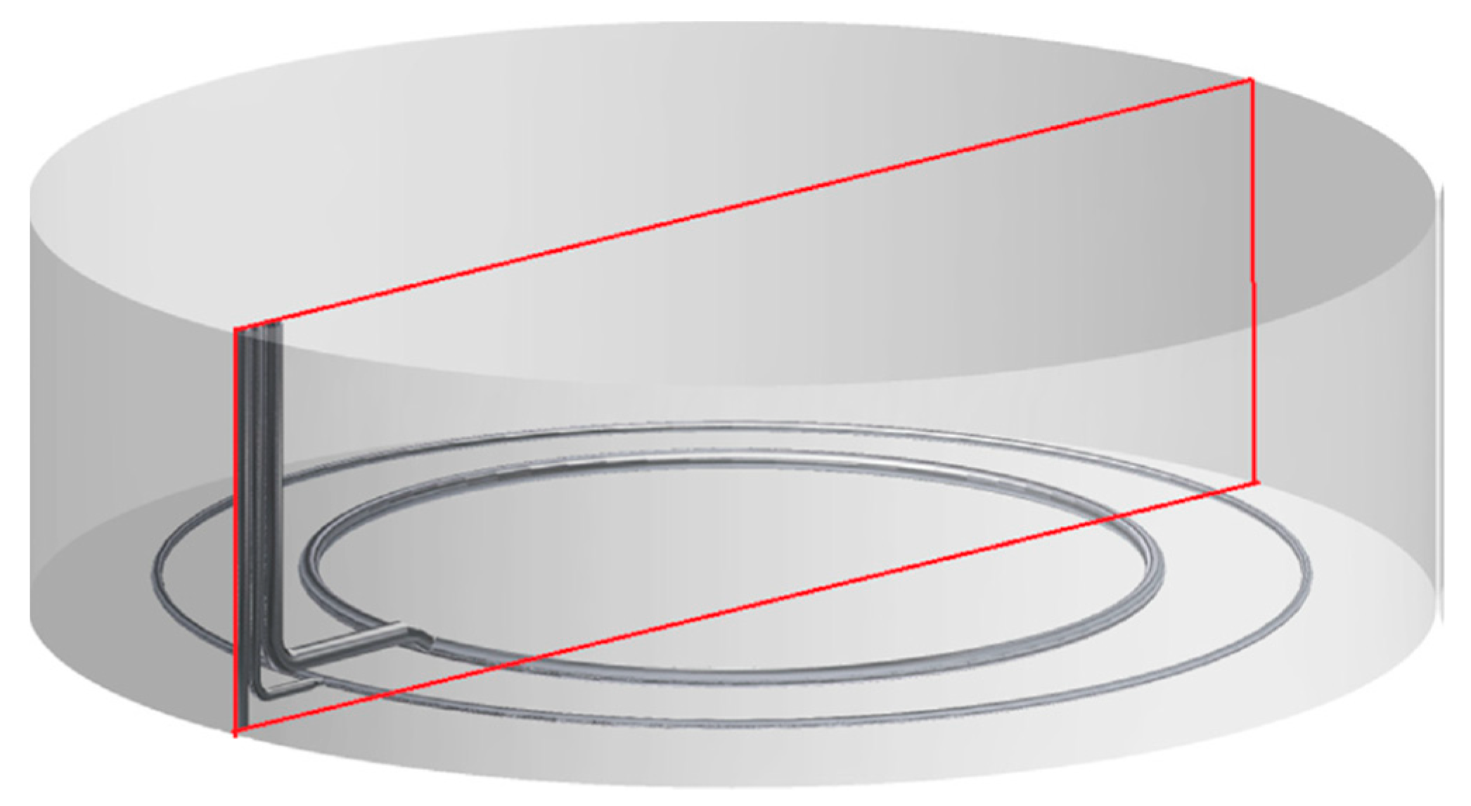
  • Expansion requirement design: To accommodate the free thermal expansion of molten salt tanks during the initial heating phase, all connections to main pipes or fixed equipment are designed with expansion joints. This design feature ensures seamless transitions from ambient temperature to working temperature, preventing structural stresses.
  • Tank Diameter and Material Correlation: The tank diameter is intricately linked to both storage capacity and molten salt temperature. Higher storage temperatures result in a reduced tank volume requirement due to the higher energy density of molten salts. However, the maximum diameter is contingent on the tank’s construction material, determined by its operating temperature. For solar power plants utilizing PTC technology, the standard of maintaining uniformity in both material and diameter for both tanks is recommended, simplifying design, construction, and maintenance processes [17]. These tanks work with salts below 400 °C and may be manufactured using ASTM A516 Gr70 carbon steel [16], capable of withstanding corrosion caused by molten salts at those temperatures. In the tower plant, the molten salt works at temperatures above 500 °C; commonly used materials include AISI 347H and AISI 321H, as well as other stainless steels such as AISI 316L and AISI 304 [16,17,19,20]. These stainless steels offer better resistance to corrosion at higher temperatures but come with increased costs and a lower maximum tank diameter of around 40 m.
  • Thickness Oversizing for Corrosion Protection: The oversizing of the thickness of the tank must be designed according to the annual corrosion ratio of the material in contact with the salts at these temperatures so that this may vary from one tank to another. This thickness shall be designed to consider all years of the life cycle of the storage system. Considering a plant life cycle of 30 years and corrosion rates for the cold tank (ASTM A516 Gr. 70 at 400 °C) of 0.078 mm/year [21] and for the hot tank (AISI A-347H at 600 °C) of 0.0088 mm/year [22], the thickness oversizing should be minimum 2.34 mm for the cold tank and 0.264 mm for the hot tank. However, for safety reasons, the thickness oversize must be higher than the minimum.
  • Roof Design and Impact on Tank Integrity: The design of the tank’s roof is crucial, influencing its ability to withstand vacuum and overpressure failures. The tank’s shape is also significant, determining its maximum overpressure capacity and stress in joints. Tanks with an ellipsoidal roof welded to the shell can withstand higher overpressures and generate less stress in joints compared to spherical or flat cap designs. Increasing the elevation of the roof further enhances the tank’s ability to withstand overpressure as the radius of curvature in the cylindrical shell–roof joint increases [16].
An integral aspect that demands meticulous attention in tank design is the foundation. The foundation’s robustness becomes paramount as it bears the mechanical stress stemming from the tank’s weight. Simultaneously, it must endure the temperature fluctuations inherent in the tank’s operational life cycle. Recognizing the foundation as a critical component underscores the need for precision in its design, ensuring not only structural integrity but also longevity and resilience against the dynamic interplay of mechanical forces and varying temperatures. Additionally, the goal is to minimize thermal losses from the tank to prevent a loss of efficiency in storage.
Some foundation designs face the challenge of reducing the dead volume of salts, a critical space ensuring proper submersion of pumps. To address this consideration, designs utilize truncated cone bottoms. These bottoms, with their distinctive shape, not only help optimize the dead space but also provide an efficient solution to ensure effective pump operation.
In conclusion, meticulous consideration is given to the thermal elongations experienced by both the shell and the tank bottom, factoring in the intricacies of the preheating phase and operational cycles. The overarching design considerations are strategically aimed at averting the generation of excessive stresses in critical areas, encompassing the bottom plates, annular rings, and tank walls. Additionally, there is a focused effort to proactively mitigate the potential risk of bottom plate buckling.
The foundation, a critical aspect of this design, is meticulously crafted to bear the mechanical stress imposed by the tank weight while simultaneously enduring the temperatures encountered throughout its life cycle. Comprising multiple layers of diverse materials, the foundation configuration is illustrated in Figure 3. The following sections delineate the possible layers and the materials suitable for each, providing a comprehensive overview of the foundation composition [16]:
  • A layer of fine sand just after the bottom of the tank.
  • A wide layer of insulating refracting bricks or expanded clay.
  • A layer of insulating material, which could be made of glass foam or ceramic fiber.
  • A thick layer of reinforced concrete. This concrete is cooled by an air- or water-cooling system to avoid high temperatures that compromise its structural integrity, if necessary.
  • A last layer of poor concrete, between the reinforced concrete and the soil.
To ensure the safety and reliability of the foundation, the incorporation of temperature sensors is imperative. These sensors will be strategically distributed to measure the foundation’s temperature, validating that it consistently maintains safe values.
The cooling system, an integral part of this design, features horizontal tubes seamlessly embedded within the reinforced concrete structure. Typically, these tubes are interlinked with fans, facilitating the passage of ambient air to dissipate heat. In scenarios demanding enhanced heat evacuation, a water-cooling system will be implemented. This system involves pumps propelling water through the tubes, providing an effective mechanism for temperature regulation and further ensuring optimal operational conditions [16].
To conclude the design review of the tanks, it is imperative to emphasize that for the seamless operation of molten salt tanks, meticulous attention to detail is paramount. A specific requirement involves achieving a precise degree of mixing within the tank. This becomes even more critical in the cold tank, given its proximity to the melting point. The heightened importance in this context arises from the cooling effects induced by the thermal losses of the tank, which have the potential to create thermal stratification and, consequently, cold spots. To address this operational challenge, the design mandates the incorporation of internal circulation rings or a set of ejectors within the salt tanks. These elements play a pivotal role in inducing a circulation flow and facilitating the thorough mixing of salts inside the tank [20]. Their function is essential to maintaining a homogeneous temperature profile, safeguarding against undesirable thermal variations. This system is intelligently designed to activate during both normal system operation and the internal recirculation mode. For a visual representation, refer to Figure 4, which illustrates the typical configuration geometry of circulation rings in a molten salt tank. This schematic elucidates the strategic placement and function of these elements, reinforcing their integral role in promoting effective mixing and ensuring a consistently uniform temperature profile.

3. Common Failures in Molten Salts Tanks

In recent years, some incidents with tank failures in concentrated solar power plants have appeared, resulting in huge economic losses [11]. This section analyses the main causes of failures in molten salt tanks, which are mainly due to corrosion, thermal shock, and thermal deformation.

3.1. Corrosion

This paper does not aim to do a comprehensive review of this topic since further information is already available in the literature [23,24,25,26,27,28,29,30].
Corrosion is defined as the thermodynamically driven degradation of materials. Molten salt at elevated temperatures is corrosive, and its level of corrosivity increases with temperature. This is the reason why the material of the tanks will depend on the temperature at which they store the salts. Corrosion can occur in various ways, among which the most common and relevant in molten salt tanks are hot corrosion, localized corrosion, mechanically assisted corrosion, and flow-accelerated corrosion [23].
Hot corrosion is defined as “accelerated corrosion of metal surfaces that results from the combined effect of oxidation and reactions with sulfur compounds and other contaminants, such as chlorides, to form a molten salt on a metal surface that fluxes, destroys, or disrupts the normal protective oxide” [31].
There are two types of hot corrosion; on the one hand, high-temperature hot corrosion (HTHC) occurs at temperatures higher than the melting temperature of the salt. On the other hand, low-temperature hot corrosion (LTHC) refers to the damage produced at temperatures below the melting point of the salt. In the tanks, since the salts are molten, the type of corrosion that concerns them is HTHC.
A common characteristic of hot corrosion is the change in the rate of weight loss, which makes it possible to distinguish between an initiation stage, characterized by a rate similar to that of the absence of the deposit, and a propagation stage, during which the rate is fast [23].
Localized corrosion can be defined as the appearance of small and deep indentations, known as pitting corrosion, or the preferential degradation of metals around a confined volume of electrolyte, called crevice corrosion. For this type of localized corrosion to occur, the formation of a protective layer of corrosion products is necessary.
The first phase of localized corrosion can occur immediately or after weeks or even years. The absence of pitting in short intervals does not imply that the metal is resistant to this type of corrosion, and it is necessary to ensure that pitting does not occur in the long term. Once corrosion has started, a pit spreads rapidly through the interior of the metal. An alternative to stop this corrosion is by clogging the pit with insoluble corrosion products [23].
One of the most relevant forms of localized corrosion in salt tanks is intragranular attack. It is the type of corrosion most commonly found in alloys exposed to molten chlorides in oxidizing atmospheres [32]. Localized corrosion becomes even more dangerous and critical if the corroded alloy is exposed to mechanical stress, as shown in [33]. Preferential attack of grain boundaries is one of the major concerns in materials used for molten salt containment [34]. Chemical species present at grain boundaries could be more likely to be oxidized, dissolved, etc., than the chemical species present in the grains, which consequently leads to a greater depth of damage where the grain boundaries are in contact with the salt [35].
Mechanically assisted corrosion encompasses stress corrosion cracking (SCC) induced by cyclic loading and corrosion fatigue resulting from thermal cyclic behavior. The confluence of mechanical stress and corrosion reactions in this scenario leads to the perilous propagation of cracks. When selecting materials for the tank shell, it becomes imperative to account for this type of corrosion, as even materials with exceptional corrosion resistance may prove inadequate when subjected to mechanical stress. The stresses requisite for such corrosion are relatively small and typically exhibit tensile characteristics [23,36].
Flow-accelerated corrosion, also known as dynamic corrosion, depends mainly on the flow velocity. At low velocities, the depletion of cathodic reactants is avoided, and the removal of soluble corrosion products is accelerated. In contrast, at higher speeds, erosion of the protective deposits may take place, and at even higher speeds, erosion of the base material may occur. In the case of erosion, the angle of impact and the turbulence of the flow are fundamental [23].
This paper focuses on the corrosion induced by solar salt. Most studies evaluate corrosion under static conditions where corrosion samples are immersed in crucibles containing molten salts, maintained at a constant temperature, and in a controlled atmosphere. These static conditions replicate the conditions inside the tanks.
Nevertheless, dynamic corrosion studies are imperative for the design of piping systems and receivers. Recent experimental investigations underscore that an elevation in flow velocity typically correlates with a substantial increase in the corrosion rate [29,37,38,39]. The corrosion rate depends on process and film temperature, container material, and salt’ composition. This paper summarizes the behavior of the most interesting steels for the construction of TES systems. In applications with temperatures below 400 °C, the industry commonly employs carbon steel, specifically the ASTM 516 Gr. 70 alloy. Conversely, for higher-temperature applications, stainless steels such as AISI 347H, AISI 316L, AISI 321, and AISI 304 are frequently utilized.
The methodologies used to analyze the corrosion rates are weight gain, weight loss, weight loss by dynamic gravimetric analysis, electrochemical polarization, and electrochemical impedance spectroscopy [23]. Table 1 presents the increase in the thickness of the pipelines for the service life, which is usually 25 years. Table 2 and Table 3 values are corrosion rates in microns per year for molten salt tank materials.
The alloy ASTM A516 Gr. 70 has been shown to resist corrosion caused by binary solar salt for temperatures up to 400 °C, generally with low thickness loss rates, below 100 microns per year. However, the corrosion rate has a strong dependence on the percentage of chlorides present in the salt, increasing rapidly as this percentage grows, as can be seen in Table 2. Hence, this salt will be required to be as pure as possible. From the corrosion data in the literature, it can be concluded that the more hours the metal is exposed to salts, the lower the corrosion rate, suggesting that the corrosion rate decreases over time. It should also be noted that at temperatures above 400 °C, the rate of corrosion increases considerably. Therefore, it is concluded that the A516 Gr. 70 alloy has good performance in terms of corrosion caused by contact with solar salt, and its use is recommended in applications at temperatures of up to 400 °C.
The analyzed results focus on static tests with immersion specimens, where the impact of chlorine content is observed to be very relevant. The impact of chloride content is more relevant in carbon steel than in stainless steel. This has led CSP technology to work with high-purity salts. Currently, refined nitrate salts with chlorine content below 0.1% are used. The test results indicate a corrosion allowance of 0.5 mm for molten salt corrosion in static conditions, deemed adequate for typical scenarios. However, recent findings suggest that a reduced allowance of 0.24 mm might be necessary under certain circumstances, such as when the preheating process is suboptimal [49]. Moreover, post-mortem corrosion tests highlight the influence of intermittent exposure during tank filling and emptying on corrosion rates [27]. This review emphasizes the difficulty in achieving corrosion allowance adjustments solely based on laboratory tests, stressing the need for real-world validation in commercial tank environments. As an interim solution, current carbon steel tanks are recommended to have a 2 mm corrosion allowance. A more accurate measure should be proposed through the analysis of immersion coupons installed in commercial tanks.
Austenitic stainless steels are used in molten salt facilities at temperatures above 400 °C. The stainless steels analyzed in Table 3 have superior properties in terms of corrosion and are used up to 550–570 °C. All the alloys analyzed in the table present good results in terms of corrosion rates for temperatures below 600 °C, especially alloys AISI 347H, AISI 347, AISI 316L, and AISI 316. For temperatures above 600 °C, the corrosion rates increase strongly. Regarding resistance to corrosion caused by molten salt flows, the AISI 316L alloy has the lowest rate of corrosion and, consequently, is recommended for piping.
AISI 347H is the material proposed for the hot tank. Due to austenitic stainless steel is not affected by the preheating process, 10 µm/year can be used as a corrosion rate reference under static conditions at 565 °C. This would yield a corrosion allowance of 0.3 mm over 25 years. However, given the challenge of replicating all the conditions occurring in commercial plants, this value is doubled as a safety factor.

3.2. Thermal Shock

During their operation, the alloys that form the shell of the salt tanks could experience thermal gradients, which generate stresses in the material. If these thermal gradients are too high, the stresses generated could be of such a magnitude that they result in the rupture of the tank [11,50]. Temperature gradients in molten salt tanks can be divided into two main groups: gradients as a function of time and those as a function of space, also called temporal and geometric gradients, respectively.
Temporary temperature gradients, which could cause thermal shock, occur when the tank is charged, especially after long plant shutdowns. They are caused due to temperature differences between the molten salts entering the tank and the molten salts inside it. As soon as the salts are properly mixed, these gradients are attenuated or disappear. To avoid these shocks, it is important that the salts inside the tank are at their nominal temperature. If the difference in temperature between the molten salts inside the tank and those entering it is higher than 50 °C, the salts must be cooled before entering, and a slow tank preheating must be programmed.
Geometric thermal gradients refer to differences in temperature between one point and another in the salt tank. One of the main reasons for the existence of this type of gradient is the cooling of the tank by differential thermal losses. This phenomenon occurs in areas where the effective thermal conductivity increases due to the existence of thermal bridges caused by deteriorated or poorly installed insulation. As a result, local cold spots can generate a dangerous thermal gradient in the alloy.
The main solutions to this problem are, on the one hand, a correct design, installation, and maintenance of the tank insulation. On the other hand, the implementation of circulation rings or ejectors promotes the circulation of salt flow inside the tank, thus homogenizing temperatures [15].

3.3. Thermal Expansion

The high working temperature of the tank leads to relevant thermal expansion. The thermal linear expansion coefficients of the most used alloys in the design of TES systems are summarized in Table 4. These coefficients and the expansions caused depend on the operating temperature of the tank. The table also shows the increase in diameter of a hypothetical tank with an original external diameter of 40 m at 20 °C.
As can be seen in Table 4, the increase in the diameters of the tanks is a significant factor. Therefore, there must be an overlap of the insulation so that when the thermal expansion of the metal structure ends, there is no gap or opening between the tank body and the outside. A total insulation surface slightly higher than that calculated for the tank at ambient temperature will be required. The extra insulation needed will depend on the diameter of the tank, the material it is made of, and its operating temperature [11]. On the other hand, the thermal expansions suffered by the tank imply that it cannot be anchored to a fixed point since it needs to expand freely.
In general, welds between shell courses and shell to bottom are very sensitive and prone to failure for any of the mechanisms described above. For tanks operating at high temperatures, it is always recommended to apply PWHT (Post-Weld Heat Treatment). Actually, API650 recommends its use for tank shell thickness greater than a certain value. PWHT reduces residual stress at welds and thermally affected zones, which is recommended to avoid stress corrosion cracking and material embrittlement. The use of PWHT is recommended for both carbon-steel and stainless-steel-based tanks. The procedure is well documented in standards and literature.

4. Modelling

The design and optimization of molten salt tanks requires a very advanced knowledge of the thermal and fluid dynamic phenomena involved. Due to the complexity of the phenomena associated with the behavior of these systems, their optimization presents a great challenge. Despite this, the designs are generally based on simple mathematical models and experimental analyses with scale prototypes, from which data necessary for the model are extracted. However, there are also more complex and detailed models capable of predicting the behavior of the system without the need for experimental data based entirely on mathematical equations [54]. Table 5 summarizes and classifies the molten salt tank models extracted from the literature.

4.1. Empirical Models

Global or empirical models have the advantage that they are more computationally efficient in terms of CPU processing time, which makes them suitable for studying the long-term behavior of salt tank systems. However, its main disadvantage is the need for empirically based information to refine the model in order to accurately predict the different operating conditions of the system. A few decades ago, it was very common to use one-dimensional (1D) numerical models to predict the operation of salt tanks due to their low computational cost compared to models in second- (2Ds) and third-dimension (3D) [54].
There are several global models in the literature. In 1989, Ghadar [55] developed a semi-implicit 1D numerical model of the stratification of salts inside a vertical cylindrical tank, used to simulate the loading and unloading of the tank. A year later, Alizadeh [56] developed two 1D models to analyze the thermal behavior of a horizontal cylindrical tank, known as the “Turbulent Mixing Model” and the “Displacement Mixing Model”. Almost two decades later, in 2009, Gabbrielli [16] used three different models, one of them to evaluate the temperature profile inside the tank and its losses with the outside, another to analyze unstable cooling of molten salts in periods of stop and, finally, a model based on FEA to evaluate the stresses in the tank plates. In 2012, Pérez-Segarra [57] presented a numerical method to model molten salt tanks. The objective is to use the NEST platform to develop a versatile methodology that implements different modeling levels for the components of a tank. On this platform, the modeled storage tank is considered as the sum of its different parts, and for each of these parts, several approach models were considered, depending on the required precision. In this study, several models are elaborated. On the one hand, there are four global models: for the energy balance of molten salts, for the energy balance of the gas between the molten salts and the tank top walls, for the free surface of the molten salts, and for solving the energy balance of the passive cooling system implemented in the foundation of the tank. On the other hand, the authors also elaborate two 1D models for the conduction of heat through the wall of the tank and through the foundation. In 2013, Zaversky [58] used the modeling language known as Modelica to model transient heat loss in molten salt tanks. The model developed for the tank walls, the roof, and the bottom is a 1D multilayer conduction model.
Table 5. Molten salt tanks models extracted from the literature.
Author, Year and ReferenceType of ModelDescription
Ghadar et al., 1989 [55]1D modelStratification of salts inside a vertical cylindrical tank
Alizadeh 1990 [56]1D modelTurbulent Mixing Model. Stratification of salts inside a horizontal cylindrical tank
1D modelDisplacement Mixing Model. Stratification of salts inside a horizontal cylindrical tank
Schulte-Fischedick et al., 2008 [59]2D CFD modelHeat losses and temperature distribution
3D CFD modelHeat losses and temperature distribution
Gabbrielli and Zamparelli 2009 [16]Global modelTemperature profiles and heat losses
Global modelUnsteady Cooling of the Molten salts
Pérez-Segarra et al., 2012 [57]Global modelEnergy balance of molten salts
Global modelEnergy balance of the gas between the molten salts and the top tank walls
Global modelMolten-salt free surface
Global modelEnergy balance of the passive cooling system implemented in the foundation
1D modelConduction of heat through the tank wall
1D modelConduction of heat through the foundation
Rodríguez et al., 2013 [54]3D CFD modelResolution of the fluid flow and heat transfer of the molten salts fluid
3D CFD modelHeat conduction through tank wall composed of multiple layers of material
Zaversky et al., 2013 [58]1D modelHeat conduction through tank walls, the top and the bottom
Suárez et al., 2015 [60]2D CFD modelCooling process in molten salt tanks
Suárez et al., 2015 [61]2D CFD modelHeat losses at the multilayer bottom of the tank in steady state
Wan et al., 2020 [11]2D CFD modelDistribution of temperatures and thermal losses of a tank in steady state
Zhang et al., 2021 [62]3D CFD modelDischarge operation of a molten salt tank for three inlet velocity conditions
Tagle-Salazar et al., 2023 [63]Global modelTransient thermal modeling of molten salt tank

4.2. Physical Models

On the other hand, detailed or physical models are based on the multidimensional resolution of the Navier–Stokes equations and the energy equations. These models should be able to accurately describe the thermal and fluid dynamic behavior of salt tanks. In the last decades, detailed numerical simulations using computational fluid dynamics (CFD) codes have become a great tool for the prediction of these systems. However, these models require a large number of computational resources, which means that long-term system behavior simulations are very expensive [54].
CFD models are used to calculate temperature distribution, salt flow rates, and heat losses from tanks. These models are of great interest because they allow the analysis and study of the complex physics present inside the tanks, especially in the cooling process, in which there is a risk of salt freezing. Another goal of CFD model analysis is the generation of specific correlations for heat transfer inside the tanks based on the modeling results. These new correlations could finally be used in the global performance model of the plant [54].
The most widely used models in the literature for calculating TES systems for salt tanks are k-ε turbulence models: the standard k-ε model, generally used in the case of a full tank, the RNG k-ε model, and the k-ε achievable, which gives significantly more accurate results in transient stages and when the tank is partially full or empty [59,60]. Both 2D and 3D CFD models are currently used, even though 3D models are more accurate. This is due to the high computational resources required by 3D models, which in certain circumstances makes them unfeasible.
Turbulence k-ε models are used to simulate flow characteristics under turbulent conditions. They are two-equation models in which two differential equations are solved, whose dependent variables are the turbulent energy “k” and the turbulent energy dissipation rate “ε” [64]. In 1974, Launder [65] proposed the standard k-ε turbulence model based on the Jones energy dissipation model [66]. Almost two decades later, in 1992, the RNG k-ε turbulence model was developed by Yakhot [67], using the Re-Normalization of Groups (RNG) mathematical method to renormalize the Navier–Stokes equations. Finally, Shih [68] developed, in 1995, the realizable k-ε model. This model is an improved version of the standard k-ε model, and it proves to give better results than the standard model in most cases.
There is a wide variety of models that have been developed to define, simulate, and predict the behavior of molten salt tanks, both in operation and in shutdown. In 2008, in the work of Schulte-Fischedick [59], a CFD analysis was carried out to obtain information on the heat losses and temperature distribution of a TES system by large-scale molten salt tanks. A CFD model in 2D and another in 3D was elaborated, both using the Ansys Fluent commercial software. Rodríguez [54], in 2013, used a modular object-oriented methodology, using the NEST platform as a link between different elements to create a specific system. This work is the continuation of that presented by Pérez-Segarra [57], previously mentioned. The models used to fully define the tank were global, 1D, and 3D models. The model to analyze the flow and heat transfer in salts is called the code TermoFluids CFD&HT, with which the three-dimensional Navier–Stokes equations are solved. In 2015, Suárez [60] elaborated a 2D CDF model to analyze the cooling process in molten salt tanks using the realizable k-ε turbulence model. In a second paper [61], published by this author in the same year, a 2D CFD multilayer analytical model is elaborated for the estimation of heat losses at the bottom of the tank in a steady state. In both works, Ansys Fluent was used for the simulations. Wan [11], in 2020, developed a 2D CFD model, simulated in Ansys Fluent, to determine the distribution of temperatures and thermal losses of a molten salt tank in a steady state. For this, the realizable k-ε turbulence model was used. Finally, Zhang [62], in 2021, models the discharge operation of a molten salt tank for three inlet velocity conditions. For this purpose, 3D equations based on the RNG k-ε model are used and subsequently solved using Ansys Fluent.

4.3. Heat Loses to Ambient

The authors generally agree on the modeling of heat losses from molten salt tanks, with very similar approaches [54,58,69,70]. Figure 5 shows the temperature distributions and heat flow scheme of a tank. The heat losses from these types of tanks are divided into three main heat flows:
  • First of all, there were losses through the roof of the tank. On the one hand, the molten salt transfers heat by convection to the gas inside the tank, and this, in turn, transfers it to the roof of the tank. On the other hand, salts also transfer heat to the roof by radiation. Since nitrogen and dry air have a symmetrical molecular structure and do not emit or absorb radiation in the considered temperature ranges [71], it is not necessary to take them into account in the radiation heat transfer analysis [58].
  • Second, the losses that occur through the tank walls come from three heat flows: the convective heat flow between the gas inside the tank and the walls of the tank, the radiant flow between salts and walls, and finally, the convective heat flow between the salts and the walls. In a similar way to what happens with roof losses, the heat flux passes through the structural material of the tank and its insulation by conduction to finally be transferred to the environment by convection and radiation.
  • There are losses through the bottom of the tank due to convective heat transfer between the salts and the bottom. This convective heat flux transmitted by the salts passes through the structural and insulating material of the bottom by conduction. Once the heat flux reaches the concrete layer, part of the heat would be dissipated by a cooling system if one were installed. Subsequently, the remaining heat flux continues to advance through the concrete until it is transferred to the ground.
  • A new study [63] proposes a mathematical model for the thermal losses in these tanks, both under nominal conditions and during transients. The dynamic thermal model includes the estimation of local heat loss due to assembly defects, which are heat flows that cannot be determined by theoretical modeling. Simulation results showed that this local heat loss may represent approximately 40% of the total heat loss in a small-scale tank.

5. Conclusions

The study highlights the importance of energy storage technology based on molten salt tank technology for concentrating solar power (CSP) plants, where the high level of maturity of this key component is evident. The viability of thermal storage systems relies on the reliability of the tank design.
The study delves into these design aspects of molten salt tanks from a multidisciplinary perspective, including factors such as material selection, insulation, and foundation design. It also encompasses a critical aspect, which is the thermal–mechanical and computational fluid dynamics modeling and analysis of this component, validating its fatigue behavior and studying losses to maximize efficiency.
The study provides a state-of-the-art overview of the various forms of corrosion to which molten salt tanks may be exposed, discussing factors such as high-temperature corrosion, localized corrosion, mechanically assisted corrosion, and flow-accelerated corrosion. Corrosion rates for different materials and salt compositions are presented, underscoring the importance of material selection.
This analysis has demonstrated the complexity of modeling and simulating molten salt tank systems, presenting a state-of-the-art that encompasses both global and detailed models, as well as the use of CFD models to predict temperature distributions, heat losses, and thermal behavior in molten salt tanks. The synergy of those models empowers us to fine-tune the design and operation of molten salt tanks. This extensive modeling experience is pivotal in increasing the reliability and overall effectiveness of molten salt tank-based systems.
In summary, the study provides valuable insights into existing knowledge and becomes an essential reading before addressing the design, operation, and challenges associated with molten salt tanks for thermal energy storage in the CSP sector.

Author Contributions

Conceptualization, C.P. and L.F.C.; methodology, C.P. and J.V.; formal analysis, L.F.C. and G.G.; investigation, C.P. and A.B.; resources, C.P. and L.F.C.; data curation, L.F.C.; writing—original draft preparation, C.P. and A.B.; writing—review and editing, L.F.C., J.V. and G.G.; visualization, C.P.; supervision, C.P. and L.F.C.; project administration, C.P. and L.F.C.; funding acquisition, C.P. and L.F.C. All authors have read and agreed to the published version of the manuscript.

Funding

This work was partially funded by the Ministerio de Ciencia e Innovación de España [(PID2021-123511OB-C31—MCIU/AEI/FEDER, UE) (TED2021-132216A-I00) (RED2022-134219-T)].

Data Availability Statement

Data are available under request to the correspondence authors.

Acknowledgments

The authors at University of Lleida would like to thank the Catalan Government for the quality accreditation given to their research group GREiA (2017 SGR 1537). GREiA is a certified agent TECNIO in the category of technology developers from the Government of Catalonia. This work is partially supported by ICREA under the ICREA Academia programme.

Conflicts of Interest

Author Guillermo García was employed by the Build to Zero S.L. Author Cristina Prieto was Scientific Advisor at the Build to Zero S.L. Author Juan Valverde was Scientific Advisor at Virtualmechanics S.L. The remaining authors declare that the research was conducted in the absence of any commercial or financial relationships that could be construed as a potential conflict of interest.

Abbreviation

CSPConcentrating solar power
TESThermal Energy Storage
CRSCentral Receiver System
PTCParabolic Trough Collector
HTFHeat Transfer Fluid
SPTSolar Power Tower
HSFHeliostat Solar Field
MSMolten salts
FEAFinite Element Analysis
HTHCHigh Temperature hot Corrosion
LTHCLow Temperature Hot Corrosion
SCCStress Corrosion Cracking
WGWeight Gain
biWLWeight Loss
CFDComputational Fluid Dynamics

References

  1. Prieto, C.; Cooper, P.; Fernández, A.I.; Cabeza, L.F. Review of technology: Thermochemical energy storage for concentrated solar power plants. Renew. Sustain. Energy Rev. 2016, 60, 909–929. [Google Scholar] [CrossRef]
  2. Py, X.; Sadiki, N.; Olives, R.; Goetz, V.; Falcoz, Q. Thermal energy storage for CSP (Concentrating Solar Power). EPJ Web Conf. 2017, 148, 14. [Google Scholar] [CrossRef]
  3. SolarPACES. What Happened with Crescent Dunes. Solarpaces.org, 23 August 2023. Available online: https://www.solarpaces.org/what-happened-with-crescent-dunes/ (accessed on 10 October 2023).
  4. Solarpaces. Solar Electric Generating Station. CSP Project. 5 December 2021. Available online: https://solarpaces.nrel.gov/project/solar-electric-generating-station-i (accessed on 15 August 2023).
  5. Solarpaces. Concentrating Solar Power Projects. 6 Diciembre 2021. Available online: https://solarpaces.nrel.gov/ (accessed on 15 August 2023).
  6. Awan, B.; Khan, M.; Zubair, M.; Bellos, E. Commercial parabolic trough CSP plants: Research trends and technological advancements. Sol. Energy 2020, 211, 1422–1458. [Google Scholar] [CrossRef]
  7. Zhang, H.; Baeyens, J.; Degrève, J.; Cacères, G. Concentrated solar power plants: Review and design methodology. Renew. Sustain. Energy Rev. 2013, 22, 466–481. [Google Scholar] [CrossRef]
  8. Bauer, T.; Odenthal, C.; Bonk, A. Molten Salt Storage for Power Generation. Chem. Ing. Tech. 2021, 93, 534–546. [Google Scholar] [CrossRef]
  9. Sandia National Laboratories. Final Test and Evaluation Results from the Solar Two Project. January 2002. Available online: https://www.osti.gov/biblio/793226 (accessed on 15 August 2023).
  10. Palacios, A.; Barreneche, C.; Navarro, M.; Ding, Y. Thermal energy storage technologies for concentrated solar power. A review from a materials perspective. Renew. Energy 2020, 156, 1244–1265. [Google Scholar] [CrossRef]
  11. Wan, Z.; Wei, J.; Qaisrani, M.A.; Fang, J.; Tu, N. Evaluation on thermal and mechanical performance of the hot tank in the two-tank molten salt heat storage system. Appl. Therm. Eng. 2020, 167, 114775. [Google Scholar] [CrossRef]
  12. API Standard 650; Welded Tanks for Oil Storage (12th edition). American Petroleum Institute: Washington, DC, USA, 2013.
  13. ASME. Section II—Materials, Part D. In ASME Boiler & Pressure Vessel Code; ASME: New York, NY, USA, 2021. [Google Scholar]
  14. ASME. Section VIII—Rules for Construction of Pressure Vessels, Division 2—Alternative Rules. In ASME Boiler & Pressure Vessel Code; ASME: New York, NY, USA, 2021. [Google Scholar]
  15. Iranzo, A.; Suárez, C.; Guerra, J. Mixing enhancement in thermal energy storage molten salt tanks. Energy Convers. Manag. 2018, 168, 320–328. [Google Scholar] [CrossRef]
  16. Gabbrielli, R.; Zamparelli, C. Optimal Design of a Molten Salt Thermal Storage Tank for Parabolic Trough Solar Power Plants. J. Sol. Energy Eng. 2009, 131, 041001. [Google Scholar] [CrossRef]
  17. González-Roubaud, E.; Pérez-Osorio, D.; Prieto, C. Review of commercial thermal energy storage in concentrated solar power plants: Steam vs. molten salts. Renew. Sustain. Energy Rev. 2017, 80, 133–148. [Google Scholar] [CrossRef]
  18. Angelini, G.; Lucchini, A.; Manzolini, G. Comparison of thermocline molten salt storage performances to commercial two-tank configuration. Energy Procedia 2014, 49, 694–704. [Google Scholar] [CrossRef]
  19. Bradshaw, R.W.; Dawson, D.B.; Rosa, W.D.L.; Gilbert, R.; Goods, S.H.; Hale, M.J.; Jacobs, P.; Jones, S.A.; Kolb, G.J.; Pacheco, J.E.; et al. Final Test and Evaluation Results from the Solar Two Project; Sandia National Laboratories: Albuquerque, NM, USA, 2002.
  20. Prieto, C.; Miró, L.; Peiró, G.; Oró, E.; Gil, A.; Cabeza, L.F. Temperature distribution and heat losses in molten salts tanks for CSP. Sol. Energy 2016, 135, 518–526. [Google Scholar] [CrossRef]
  21. Bradshaw, R.W.; Clift, W.M. Effect of Chloride Content of Molten Nitrate Salt on Corrosion of A516 Carbon Steel; Sandia National Laboratories: Albuquerque, NM, USA, 2010.
  22. Trent, M.C.; Goods, S.H.; Bradshaw, R.W. Comparison of corrosion performance of grade 316 and grade 347H stainless steels in molten nitrate salt. AIP Conf. Proc. 2016, 1734, 160017. [Google Scholar]
  23. Walczak, M.; Pinedaa, F.; Fernández, Á.G.; Mata-Torres, C.; Escobar, R.A. Materials corrosion for thermal energy storage systems in concentrated solar power plants. Renew. Sustain. Energy Rev. 2018, 86, 22–44. [Google Scholar] [CrossRef]
  24. Patel, N.S.; Pavlík, V.; Boča, M. High-temperature corrosion behavior of superalloys in molten salts—A review. Crit. Rev. Solid State Mater. Sci. 2016, 42, 83–97. [Google Scholar] [CrossRef]
  25. Fernández, Á.G.; Cabeza, L.F. Molten salt corrosion mechanisms of nitrate based thermal energy storage materials for concentrated solar power plants: A review. Sol. Energy Mater. Sol. Cells 2019, 194, 160–165. [Google Scholar] [CrossRef]
  26. Ma, L.; Zhang, C.; Wu, Y.; Lu, Y. Comparative review of different influence factors on molten salt corrosion characteristics for thermal energy storage. Sol. Energy Mater. Sol. Cells 2022, 235, 111485. [Google Scholar] [CrossRef]
  27. Ruiz-Cabañas, F.J.; Prieto, C.; Osuna, R.; Madina, V.; Fernández, A.I.; Cabeza, L.F. Corrosion testing device for in-situ corrosion characterization in operational molten salts storage tanks: A516 Gr70 carbon steel performance under molten salts exposure. Sol. Energy Mater. Sol. Cells 2016, 157, 383–392. [Google Scholar] [CrossRef]
  28. Ruiz-Cabañas, F.J.; Prieto, C.; Madina, V.; Fernández, A.I.; Cabeza, L.F. TES-PS10 postmortem tests: Carbon steel corrosion performance exposed to molten salts under relevant operation conditions and lessons learnt for commercial scale-up. J. Energy Storage 2019, 26, 100922. [Google Scholar] [CrossRef]
  29. Zhang, X.; Zhang, C.; Wu, Y.; Lu, Y. Experimental research of high temperature dynamic corrosion characteristic of stainless steels in nitrate eutectic molten salt. Sol. Energy 2020, 209, 618–627. [Google Scholar] [CrossRef]
  30. Ibrahim, A.; Peng, H.; Riaz, A.; Basit, M.A.; Rashid, U.; Basit, A. Molten salts in the light of corrosion mitigation strategies and embedded with nanoparticles to enhance the thermophysical properties for CSP plants. Sol. Energy Mater. Sol. Cells 2021, 219, 110768. [Google Scholar] [CrossRef]
  31. NACE/ASTM G193-12D; Standard Terminology and Acronyms Relating to Corrosion. American Society for Testing and Materials: West Conshohocken, PA, USA, 2013.
  32. Lai, G.Y. Molten Salt Corrosion. In High-Temperature Corrosion and Materials Applications; ASM International: Almere, The Netherlands, 2007; pp. 409–421. [Google Scholar]
  33. Kruizenga, M. Stainless Steel Corrosion by Molten Nitrates: Analysis and Lessons Learned; Sandia National Laboratories (SNL): Albuquerque, NM, USA; Livermore, CA, USA, 2011.
  34. Liu, S.; Liu, Z.; Wang, Y.; Tang, J. A comparative study on the high temperature corrosion of TP347H stainless steel, C22 alloy and laser-cladding C22 coating in molten chloride salts. Corros. Sci. 2014, 83, 396–408. [Google Scholar] [CrossRef]
  35. Bell, S.; Steinberg, T.; Will, G. Corrosion mechanisms in molten salt thermal energy storage for concentrating solar power. Renew. Sustain. Energy Rev. 2019, 114, 109328. [Google Scholar] [CrossRef]
  36. Brown, B.F. Stress-Corrosion Cracking in High Strength Steels and in Titanium and Aluminum Alloys; Naval Research LaboratoryWashington: Washington, DC, USA, 1972. [Google Scholar]
  37. García-Martín, G.; Lasanta, M.; Encinas-Sánchez, V.; Miguel, M.D.; Pérez, F. Evaluation of corrosion resistance of A516 Steel in a molten nitrate salt mixture using a pilot plant facility for application in CSP plants. Sol. Energy Mater. Sol. Cells 2017, 161, 226–231. [Google Scholar] [CrossRef]
  38. Wang, J.; Jiang, Y.; Ni, Y.; Wu, A.; Li, J. Investigation on static and dynamic corrosion behaviors of thermal energy transfer and storage system materials by molten salts in concentrating solar power plants. Mater. Corros. 2019, 70, 102–109. [Google Scholar] [CrossRef]
  39. Sutter, F.; Oskay, C.; Galetz, M.C.; Diamantino, T.; Pedrosa, F.; Figueira, I.; Glumm, S.; Bonk, A.; Agüero, A.; Rodríguez, S.; et al. Dynamic corrosion testing of metals in solar salt for concentrated solar power. Sol. Energy Mater. Sol. Cells 2021, 232, 111331. [Google Scholar] [CrossRef]
  40. Nithiyanantham, U.; Grosu, Y.; González-Fernández, L.; Zaki, A.; Igartua, J.M.; Faik, A. Corrosion aspects of molten nitrate salt-based nanofluids for thermal energy storage applications. Sol. Energy 2019, 189, 219–227. [Google Scholar] [CrossRef]
  41. Ruiz-Cabañas, F.J.; Prieto, C.; Madina, V.; Fernández, A.I.; Cabeza, L.F. Materials selection for thermal energy storage systems in parabolic trough collector solar facilities using high chloride content nitrate salts. Sol. Energy Mater. Solar Cells 2017, 163, 134–147. [Google Scholar] [CrossRef]
  42. Prieto, C.; Gallardo-González, J.; Ruiz-Cabañas, F.J.; Barreneche, C.; Martínez, M.; Segarra, M.; Fernández, A.I. Study of corrosion by Dynamic Gravimetric Analysis (DGA) methodology. Influence of chloride content in solar salt. Sol. Energy Mater. Sol. Cells 2016, 157, 526–532. [Google Scholar] [CrossRef]
  43. Nieto-Maestre, J.; Muñoz-Sánchez, B.; Fernández, A.G.; Faik, A.; Grosu, Y.; Gar-cía-Romero, A. Compatibility of container materials for Concentrated Solar Power with a solar salt and alumina based nanofluid: A study under dynamic conditions. Renew. Energy 2020, 146, 384–396. [Google Scholar] [CrossRef]
  44. Goods, S.H.; Bradshaw, R.W. Corrosion of stainless steels and carbon steel by molten mixtures of commercial nitrate salts. J. Mater. Eng. Perform. 2004, 13, 78–87. [Google Scholar] [CrossRef]
  45. Bradshaw, R.W.; Goods, S.H. Corrosion Resistance of Stainless Steels during Thermal Cycling in Alkali Nitrate Molten Salts; Sandia National Laboratories (SNL): Albuquerque, NM, USA; Livermore, CA, USA, 2001.
  46. Dorcheh, S.; Durham, R.N.; Galetz, M.C. Corrosion behavior of stainless and low-chromium steels and IN625 in molten nitrate salts at 600 °C. Sol. Energy Mater. Sol. Cells 2016, 144, 109–116. [Google Scholar] [CrossRef]
  47. Kruizenga, A.; Gill, D. Corrosion of iron stainless steels in molten nitrate salt. Energy Procedia 2014, 49, 878–887. [Google Scholar] [CrossRef]
  48. Kruizenga, M.; Gill, D.D.; LaFord, M.E. Materials Corrosion of High Temperature Alloys Immersed in 600C Binary Nitrate Salt; Sandia National Laboratories (SNL): Albuquerque, NM, USA; Livermore, CA, USA, 2013.
  49. Prieto, C.; Ruiz-Cabañas, J.; Madina, V.; Fernández, A.I.; Cabeza, L.F. Lessons learned from corrosion of materials with molten salts during molten salt tank preheating. Sol. Energy Mater. Sol. Cells 2022, 247, 111943. [Google Scholar] [CrossRef]
  50. Luengo, C.; Cardona, A.; Risso, J. Determinación de tensiones residuales en discos sometidos a grandes gradientes térmicos durante el servicio. Mecánica Comput. 2016, 25, 461–472. [Google Scholar]
  51. Yafei, S.; Yongjun, T.; Jing, S.; Dongjie, N. Effect of temperature and composition on thermal properties of carbon steel. In Proceedings of the 2009 Chinese Control and Decision Conference, Guilin, China, 17–19 June 2009. [Google Scholar]
  52. Desai, P.D.; Ho, C.Y. Thermal Linear Expansion of Nine Selected AISI Stainless Steels; Thermophysical and Electronic Properties Information Analysis Center Lafayette IN: Washington, DC, USA, 1978. [Google Scholar]
  53. Yakout, M.; Elbestawi, M.; Veldhuis, S.C. A study of thermal expansion coefficients and microstructure during selective laser melting of Invar 36 and stainless steel 316L. Addit. Manuf. 2018, 24, 405–418. [Google Scholar] [CrossRef]
  54. Rodríguez, I.; Pérez-Segarra, C.D.; Lehmkuhl, O.; Oliva, A. Modular object-oriented methodology for the resolution of molten salt storage tanks for CSP plants. Appl. Energy 2013, 109, 402–414. [Google Scholar] [CrossRef]
  55. Ghaddar, N.; Al-Marafie, A.; Al-Kandari, A. Numerical simulation of stratification behaviour in thermal storage tanks. Appl. Energy 1989, 32, 225–239. [Google Scholar] [CrossRef]
  56. Alizadeh, S. An experimental and numerical study of thermal stratification in a horizontal cylindrical solar storage tank. Sol. Energy 1999, 66, 409–421. [Google Scholar] [CrossRef]
  57. Pérez-Segarra, D.; Rodríguez, I.; Oliva, A.; Torras, S.; Lehmkuhl, O. Detailed numerical model for the resolution of molten salt storage tanks for CSP plants. In International Conference on Solar Heating, Cooling and Buildings; Solar energy for a Brighter Future: Book of Proceedings; EuroSun: Rijeka, Croatia, 2012. [Google Scholar]
  58. Zaversky, F.; García-Barberena, J.; Sánchez, M.; Astrain, D. Transient molten salt two-tank thermal storage modeling for CSP performance simulations. Sol. Energy 2013, 93, 294–311. [Google Scholar] [CrossRef]
  59. Schulte-Fischedick, J.; Tamme, R.; Herrmann, U. CFD Analysis of the Cool Down Behaviour of Molten Salt Thermal Storage Systems. In Proceedings of the ASME 2008 2nd International Conference on Energy Sustainability Collocated with the Heat Transfer, Fluids Engineering, and 3rd Energy Nanotechnology Conferences, Jacksonville, FL, USA, 10–14 August 2008. [Google Scholar]
  60. Suárez, C.; Iranzo, A.; Pino, F.J.; Guerra, J. Transient analysis of the cooling Process of molten salt thermal storage tanks due to standby heat loss. Appl. Energy 2015, 142, 56–65. [Google Scholar] [CrossRef]
  61. Suárez, C.; Pino, F.J.; Rosa, F.; Guerra, J. Heat loss from thermal energy storage ventilated tank foundations. Sol. Energy 2015, 122, 783–794. [Google Scholar] [CrossRef]
  62. Zhang, C.; Lu, Y.; Shi, S.; Wu, Y. Comparative research of heat discharging characteristic of single tank molten salt thermal energy storage system. Int. J. Therm. Sci. 2021, 161, 106704. [Google Scholar] [CrossRef]
  63. Tagle-Salazar, P.D.; Prieto, C.; López-Román, A.; Cabeza, L.F. A transient heat losses model for two-tank storage systems with molten salts. Renew. Energy 2023, 219, 119371. [Google Scholar] [CrossRef]
  64. Launder, B.; Spalding, D. The numerical computation of turbulent flows. Comput. Methods Appl. Mech. Eng. 1974, 3, 269–289. [Google Scholar] [CrossRef]
  65. Launder, B.; Sharma, B. Application of the Energy Dissipation Model of Turbulence to the Calculation of Flow Near a Spinning Disc. Lett. Heat Mass Transf. 1974, 1, 131–138. [Google Scholar] [CrossRef]
  66. Jones, W.; Launder, B. The calculation of low-Reynolds-number phenomena with a two-equation model of turbulence. Int. J. Heat Mass Transf. 1973, 16, 1119–1130. [Google Scholar] [CrossRef]
  67. Yakhot, V.; Orszag, S.A. Development of turbulence models for shear flows by a double expansion technique. Phys. Fluids A Fluid Dyn. 1992, 4, 1510–1520. [Google Scholar] [CrossRef]
  68. Shih, T.-H.; Liou, W.W.; Shabbir, A.; Yang, Z.; Zhu, J. A new k-ϵ eddy viscosity model for high Reynolds number turbulent flows. Comput. Fluids 1995, 24, 227–238. [Google Scholar] [CrossRef]
  69. Zhou, H.; Shi, H.; Zhang, J.; Zhou, M. Experimental and numerical investigation of temperature distribution and heat loss of molten salt tank foundation at different scales. Heat Mass Transf. 2020, 56, 2859–2869. [Google Scholar] [CrossRef]
  70. Torras, S.; Pérez-Segarra, C.; Rodríguez, I.; Rigola, J.; Oliva, A. Parametric Study of Two-tank TES Systems for CSP Plants. Energy Procedia 2015, 69, 1049–1058. [Google Scholar] [CrossRef]
  71. Kreith, F.; Bohn, M.S. Principles of Heat Transfer, Stamford; Cengage Learning: Boston, MA, USA, 2016. [Google Scholar]
Figure 1. Diagram of a parabolic trough collector (PTC) technology CSP plant with a TES system.
Energies 17 00022 g001
Figure 2. Diagram of a central receiver system (CRS) technology CSP plant with a TES system.
Energies 17 00022 g002
Figure 3. Scheme of the storage tank foundation layers. Source: [16].
Energies 17 00022 g003
Figure 4. Configurations geometry of the circulation rings in a molten salt tank (the plane of symmetry is represented in red). Source: [15].
Energies 17 00022 g004
Figure 5. Temperature distributions and heat flows scheme of a tank ( Q ˙ is heat flow in W and T is temperature). Source: [63].
Energies 17 00022 g005
Table 1. Minimum corrosion thickness of molten salts pipes tested under dynamic corrosion [29,37,38,39].
AlloyTemperature (°C)Minimum Corrosion Thickness [mm]
A516 Gr. 705009.99
A516 Gr. 703852.84
AISI 3045300.51
AISI 347H5600.42
AISI 3475600.41
AISI 321H5600.50
AISI 316L5300.33
AISI 316L5600.36
Table 2. Summary of corrosion data in ASTM A516 Gr. 70 for molten salt tank.
AlloyTest ConditionsTemperature (°C)Exposure Time (h)Corrosion Rate (µm/year)Reference
A516 Gr. 70Solar salt40081078[21]
A516 Gr. 70Solar salt
0.5 Cl wt. %
400811198[21]
A516 Gr. 70Solar salt
1.0 Cl wt. %
400804405[21]
A516 Gr. 70Solar salt450642299[21]
A516 Gr. 70Solar salt
0.5 Cl wt. %
450724734[21]
A516 Gr. 70Solar salt
1.0 Cl wt. %
4506021,531[21]
A516 Gr. 70Solar salt390150092[40]
A516 Gr. 70Solar Salt
0.1 Cl wt. %
39040645.46[27]
A516 Gr. 70Solar salt IC *
0.1 Cl wt. %
39040643.57[27]
A516 Gr. 70Solar salt
0.1 Cl wt. %
39087122.14[27]
A516 Gr. 70Solar salt
1.2 Cl wt. %
4001581210 ± 7[41]
A516 Gr. 70Solar salt
3.0 Cl wt. %
4001581535 ± 7[41]
A516 Gr. 70Solar salt
Dynamic test
500100333[37]
A516 Gr. 70Solar salt
Static test
500100215[37]
A516 Gr. 70Solar salt400216547.4 ± 3.4[42]
A516 Gr. 70Solar salt
0.7 Cl wt. %
400216547.4 ± 3.4[42]
A516 Gr. 70Solar salt
1.8 Cl wt. %
4001504987.3 ± 18.6[42]
A516 Gr. 70Solar salt
Dynamic test
385100094.6[43]
* Intermittent conditions. Partially in contact with N2 and with salts, depending on the filling level of the tank.
Table 3. Summary of corrosion data in stainless steels for molten salt tank.
AlloyTest ConditionsTemperature (°C)Exposure Time (h)Corrosion Rate (µm/year)Reference
AISI 304Solar salt570700817.7[44]
AISI 304Solar salt
1.0 NaCl wt. %
570700826.6[44]
AISI 304Solar salt
1.3 NaCl wt. %
570700835.5[44]
AISI 304Solar salt TC *565443215.8[45]
AISI 304Solar salt TC
0.82 Cl wt. %
565443231.6[45]
AISI 304Solar salt565458411.5[45]
AISI 304Solar salt
0.82 Cl wt. %
565458430.6[45]
AISI 304Solar salt530196020[38]
AISI 304Solar salt530300012.5[38]
AISI 304Solar salt
Dynamic test
530196017[38]
AISI 347HSolar salt60030008.8[22]
AISI 347HSolar salt600500051[46]
AISI 347HSolar salt
Dynamic test
560112514[39]
AISI 347Solar salt40030640.7[47]
AISI 347Solar salt50030644.6[47]
AISI 347Solar salt600300010.4[48]
AISI 347Solar salt6801025447[47]
AISI 347Solar salt
Dynamic test
560112513.5[39]
AISI 321Solar salt40030641[47]
AISI 321Solar salt50030647.1[47]
AISI 321Solar salt600300015.9[48]
AISI 321Solar salt6801025460[47]
AISI 321HSolar salt
Dynamic test
560112516.5[39]
AISI 316Solar salt60030008.4[22]
AISI 316Solar salt600500061[46]
AISI 316Solar salt570700821.3[44]
AISI 316Solar salt
1.0 Cl wt. %
570700818.7[44]
AISI 316Solar salt
1.3 Cl wt. %
570700820.2[44]
AISI 316Solar salt TC565408410.7[45]
AISI 316Solar salt TC
0.82 Cl wt. %
565408423.6[45]
AISI 316Solar salt56545848.6[45]
AISI 316Solar salt
0.82 Cl wt. %
565458415.3[45]
AISI 316LSolar salt TC565408412.2[45]
AISI 316LSolar salt TC
0.82 Cl wt. %
565408412.3[45]
AISI 316LSolar salt56545848.4[45]
AISI 316LSolar salt
0.82 Cl wt. %
56545849.5[45]
AISI 316LSolar salt53019609.5[38]
AISI 316LSolar salt53030005.5[38]
AISI 316LSolar salt
Dynamic test
530196011[38]
AISI 316LSolar salt
Dynamic test
560112512[39]
* Thermal cycling.
Table 4. Thermal linear expansion coefficient and increase in diameter of the most used alloys in TES.
AlloyTemperature (°C)Thermal Linear Expansion
Coefficient (µm/m·K)
Increase in Diameter (m)Reference
AISI 516 Gr. 70 *29013.0641.41[51]
AISI 516 Gr. 70 *39013.5392.00[51]
AISI 304 **56517.7623.88[52]
AISI 316 **56518.4414.02[52]
AISI 316L56519.0254.15[53]
AISI 321 **56517.553.83[52]
AISI 347H **56518.7564.08[52]
* Calculated from the equation provided by the reference considering a carbon percentage of 0.28%. ** Interpolation of the values provided by the reference.
Disclaimer/Publisher’s Note: The statements, opinions and data contained in all publications are solely those of the individual author(s) and contributor(s) and not of MDPI and/or the editor(s). MDPI and/or the editor(s) disclaim responsibility for any injury to people or property resulting from any ideas, methods, instructions or products referred to in the content.

