Article

Graded-Index Active Layer for Efficiency Enhancement in Polymer Solar Cell

Department of Electrical Engineering, Shaqra University, Riyadh 11911, Saudi Arabia
*
Author to whom correspondence should be addressed.
Energies 2023, 16(9), 3933; https://doi.org/10.3390/en16093933
Submission received: 17 March 2023 / Revised: 23 April 2023 / Accepted: 4 May 2023 / Published: 6 May 2023

Abstract

:
In this paper, narrow-bandgap polymer acceptors combining a benzotriazole (BTz)-core fused-ring segment, named the PZT series, were used with a high-absorption-efficiency polymer (PBDB) compound with branched 2-butyl octyl, linear n-octyl, and methyl to be utilized as a graded-index (GI) active layer of the polymer solar cells (PSCs) to increase the photocurrent and enhance solar efficiency compared to the existing PBDB-T:PZT and PBDB-T:PZT-γ. In addition, a two-dimensional photonic crystal (2D-PhC) structure was utilized as a light-trapping anti-reflection coating (ARC) thin film based on indium tin oxide (ITO) to reduce incident light reflection and enhance its absorption. The dimensions of the cell layers were optimized to achieve the maximum power-conversion efficiency (PCE). Furthermore, the design and simulations were conducted from a 300 nm to 1200 nm wavelength range using a finite difference time-domain (FDTD) analysis. One of the most important results expected from the study was the design of a nano solar cell at (64 µm)2 with a PCE of 25.1%, a short-circuit current density (JSC) of 27.74 mA/cm2, and an open-circuit voltage (VOC) of 0.986 V.

1. Introduction

In recent years, the common advantages of all-polymer solar cells all-(PSCs), such as their lighter weight, flexibility, and the low-cost printing of for fabrication, have attracted significant interest [1,2,3]. At the same time, some methods have appeared that contribute to circumventing the challenges that have impeded improvements to the efficiency of solar cells that depend on semiconductors and methods for converting natural resources into electrical energy [4,5,6]. A layered PSC structure consists of at least a transparent front electrode, an active layer—which is the real semiconducting polymer material—and a back electrode fabricated on a plastic substrate. The active layer thickness is 150–400 nm, which uses significantly less material than conventional silicon solar cells [7,8]. The popularity of all-PSCs, which use conjugated polymers as electron donors or electron acceptors in the light-trapping layer [9,10,11], has increased over the past decade compared to other PSC types based on fullerene acceptors or non-fullerene small-molecule acceptors (SMAs) [12,13]. Owing to their outstanding thermal and mechanical stability, they are attracting growing interest [14,15,16,17]. Recent advances in active layer material design, device engineering, and bulk heterojunction morphology control have allowed the power-conversion efficiency (PCE) of all power-supply converters to increase by over 15%, which is potentially suitable for future practical applications [18]. PSCs are handled from a solution in organic solvents, which have gained global recognition for their good properties, such as flexibility, light weight, and low cost of manufacturing. Within fifteen years, the PCE of PSCs has increased from 1.5% to 17.5% using small-molecule polymer acceptors [19,20,21,22]. Therefore, novel n-type polymers with narrow bandgap energy and desirable characteristics that can match efficiently with the commonly utilized polymer donors are the key for further evolving all-PSCs development [23].
After all these studies and research, the increasing of cell efficiency remains a problem, and this efficiency does not exceed 18% in theory in the best previous research proposals. Therefore, the core objective of this study was to improve the cell efficiency using the following techniques:
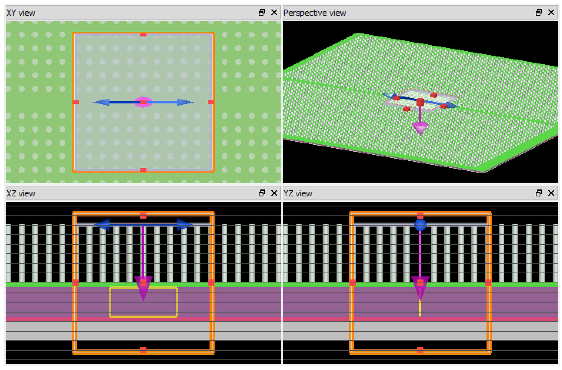
  • An indium tin oxide (ITO) anti-reflection coating (ARC) thin-film two-dimensional photonic crystal (2D-PhC) structure was optimized to reduce reflection loss, enhance the absorption coefficient, and increase the in-coupling efficiency at the solar-surface interface;
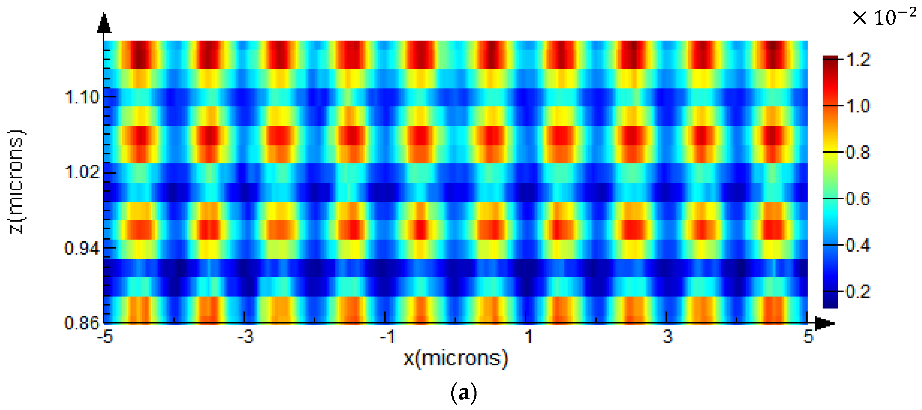
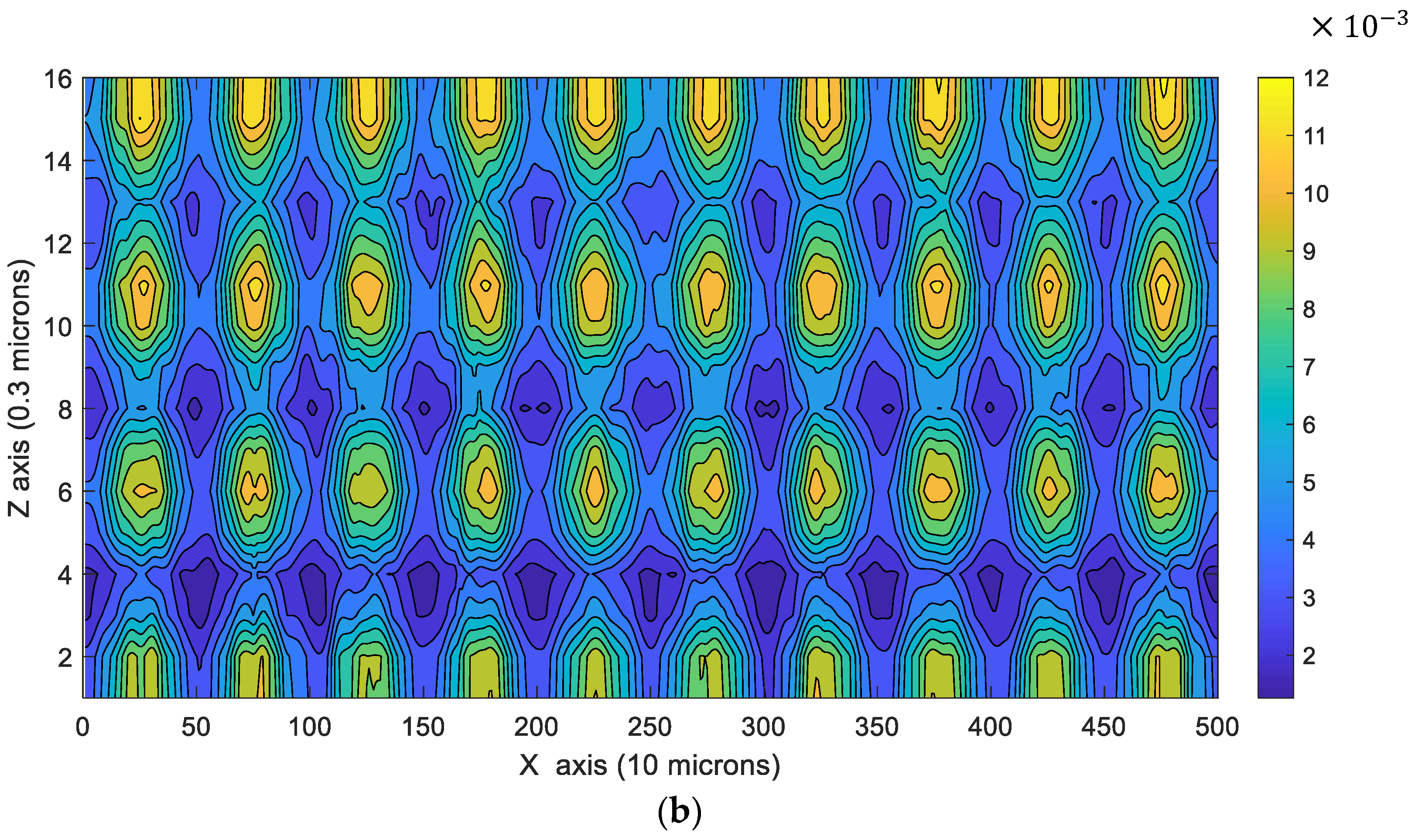
  • The active-layer refractive index was gradually distributed to improve the quantum efficiency and increase the photocurrent inside the cell heterojunction;
  • Cell-layer thicknesses were optimized and doping was made sufficient to extend the cell visibility range and thus enhance the cell-absorption coefficient again.
Nano-solar cells can be used in different applications, as they can be used as a substitute for earphones and mobile phone chargers [24,25,26,27,28]. They can also be manufactured with these devices, such that some of them are inseparable. This objective can be quantified explicitly as:
  • Designing a nano PSC of around 64 µm2 in size;
  • Increasing the in-coupling and quantum efficiency at the cell-surface interface using an optimized ITO 2D-PhC thin-film structure;
  • Using the “branched 2-butyl octyl, linear n-octyl, and methyl” (PBDB-T:GI-PZT) polymer compound as the active layer based on a graded-index (GI) technique. This compound obtained good results when used in the semiconductors polymer solar cells [23]. In this study the GI technique was used to improve the confinement characteristics of the active layer, prevent light reflection, enhance cell absorption, and increase the photocurrent;
  • Increasing the PCE to 25.1%;
  • Enhancing the cell’s electrical characteristics.
Achieving these objectives can create a large market potential for 2D-PhC crystalline semiconducting-PSCs. In addition, the main objective of this study was itemized into different specific objectives to ensure the successful control of the existing challenges in achieving the main goal. To achieve such challenging objectives, the proposed solar cell will simultaneously work on efficiency, materials, and steps toward entry and acceptance, as well as the development process, related dissemination, scale-up, and excitation. In order to design the units, it was necessary to design a new high-efficiency PSC structure. As was discussed in the literature review, most of the cells that are designed and manufactured have limitations preventing efficiencies in excess of 17.5% for all PSCs. Nano-polymer 2D-PhC technologies will achieve novel solar-cell structures that allow for greater efficiency by using the finite time-domain (FDTD) technique. In addition, the energy bandgap was studied to improve the quantum efficiency and light in-coupling efficiency. This will yield developed cells with at least a 25.1% PCE and 64 µm2 cell size.

2. Literature Review

In Ref. [1], the authors used a sol–gel TiO2 to fabricate the PSC, the results obtained from this study were a 0.67 fill factor, 9.5% conversion efficiency, and a 0.63 V open-circuit voltage.
In Ref. [2], the authors demonstrated a specific fabrication experimental model of a PSC with conversion efficiency and post-production on annealing at 150 °C. Also, the authors proved that when the series resistance of the cell is reduced, the cell-conversion efficiency increased.
In Ref. [3], the authors introduced a new cell metallization technique that could be directly applied to standard industrial cells, thus eliminating the need for rear pads and front busbars. Experiments showed that the modified cell efficiency was 0.8% higher cell efficiency when compared to reference cells. Also, the same technique was applied to eight-inch cells which obtained a result of 77.9% fill factors.
In Ref. [7], the authors investigated the effect of self-organization by controlling the growth rate on the performance of polymer/fullerene bulk-heterojunction solar cells, resulting in a 31–155 A/m2 short-circuit current and 0.62–0.4 V open-circuit voltage.
In Ref. [8], the authors investigated the submicrometric periodic patterning of an organic solar-cell surface to optimize the cell-conversion efficiency. Patterning was achieved using a single-step all-optical technique based on photoinduced mass transport in azo polymer films.
In Ref. [9], the authors investigated the effect of interfacial buffer layers—cesium carbonate Cs2CO3 and vanadium oxide (V2O5)—on the performance of PSCs based on a regioregularity poly-[3-hexylthiophene] and phenyl C60 butyric acid methyl ester blend, resulting in 8.42 mA/cm2 short-circuit current, 0.56 V open circuit voltage, and 2.25% PCE.
In Ref. [10], the authors demonstrated a reflective tandem cell where single cells reflected the non-absorbed light upon another adjacent cell. By folding two planar but spectrally different cells toward each other, the results obtained an enhancement of PCE of a factor of 1.8 ± 0.3 by combining spectral-broadening and light-trapping.
In Ref. [11], the authors constructed a PSC based on a low-bandgap polymer structure, (PBDTTT4) which can be tuned, step-by-step, using different functional groups in order to achieve open-circuit voltage as high as 0.76 V. This increased open-circuit voltage, combined with a high short-circuit current density, resulted in a polymer solar cell with a PCE as high as 6.77%.
In Ref. [12], the authors investigated a unique nano-ridge structure of zinc oxide (ZnO) and its application in high-performance inverted PSCs. The ZnO nano-ridge structure was formed by a sol–gel process using a ramp annealing method. The cell showed a PCE of 4.00%, and a 25% improvement over similar solar cells using a planar film of ZnO nanoparticles.
In Ref. [13], the authors describe a photovoltaic study and synthesis of a series of new semiconducting polymers with alternating thiophene and benzodithiophene units. Also, the authors adjusted the polymer energy levels to increase the open-circuit voltage. The achieved efficiency was higher than the efficiency of a simple planner cell by a factor of 6%.
In [15], the authors present a new class of push–pull polymers combined with a fullerene derivative in a bulk-heterojunction (BHJ) structure that enabled organic photovoltaic (OPV) efficiencies reaching 10%. This was a significant improvement compared to the 5% efficiency achieved by the well-studied polymer poly(3-hexylthiophene) (P3HT).
In Ref. [16], fluorinated organic molecules exhibited a series of unique features and achieved 7% solar conversion efficiency.
In Ref. [17], the authors developed a Cu (In, Ga)Se2 thin-film solar cell on a polyimide film. A PCE of 17.1%, measured under standard test conditions at the European Solar Test Installation (ESTI) of the Joint Research Centre (JRC) of the European Commission, Ispra, was reported.
In Ref. [18], the authors demonstrated plasmonic effects on an inverted tandem polymer solar cell configuration by blending Au nanoparticles into the interconnecting layer that connects two sub-cells. The results showed that the plasmonic-enhanced interconnecting layer improved the top and bottom sub-cells’ efficiency simultaneously by enhancing the optical absorption. The presence of Au nanoparticles did not cause electrical characteristics to degrade within the tandem cell. As a result, a 20% improvement in PCE was attained by the light concentration of Au nanoparticles via plasmonic near-field enhancement.
In Ref. [19], the authors demonstrated a polymeric retroreflective textured sheet which was produced separately and applied onto the glass substrate after completion of the solar cell. Also, the injection of donor polymers in the cell’s active layer was proposed. In this paper, the achieved PCE ranged from 5.9% to 19%.
In Ref. [20], the authors designed a single junction inverted PSC with a PCE of 10.31% using dual-doped zinc oxide nano-film as cathode interlayer and liquid-based growth of polymeric carbon nitride layers with their use in a mesostructured PSC with  V O C  exceeding 1 V.
In Refs. [21,22,23], PSCs based on the donor polymer PBDTTT-EFT for high efficiency were demonstrated and the artificial inverted compound eye-structured polydimethylsiloxane films with light harvesting and self-cleaning functions for the improvement of solar power generation in III–V encapsulated gallium arsenide single-junction solar cells were proposed. The results showed that the efficiency approached 17.5%.
Refs. [24,25,26,27] included the deposition of organic polymer films for solar-cell applications, multilayered polymer materials based on polymeric ammonium cations for stable large-area solar cells, polymer doping for high-efficiency solar cells with improved moisture stability, low-temperature processed high-performance thick-film ternary polymer solar cell with enhanced stability and solar cells using indium tin oxide thin film to enhance the solar absorption. The most-expected results from these works is the solar-cell stability at a 7–25% increase in conversion efficiency compared with the simple planner cell.
In Ref. [28], all-PSCs architecture, such as single-junction organic solar cells using a fused-ring acceptor with an electron-deficient core, biomimetic diodon-skin nano-thorn polymer antireflection film-based solar cell, nonhalogenated-solvent-processed high performance all-PSC, and a PSC based on adding a polymer mixture in the photoactive layer were demonstrated in order to improve solar-cell efficiency and stability. The best results were 19.88% PCE, 0.88 V  V O C , and 20 mA/cm2  J S C .

3. Solar Cell Modeling

Figure 1 presents the architecture of the proposed solar cell after optimization of the layer thicknesses based on a narrow-bandgap polymer PBDB compound with branched 2-butyl octyl, linear n-octyl, and methyl groups on the BTz unit, namely PZT, a graded-index (GI) active layer (PBDB-T:GI-PZT).
This compound has a high absorption efficiency, and the graded-index technique adds some significant advantages to this compound, which prevents carrier reflections from the active layer, increases the quantum efficiency, and increases the photocurrent. The poly polystyrene sulfonate, HTL layer (PEDOT:PSS), and 2D-PhC indium tin oxide (ITO) layer are confinement layers that increase the absorption efficiency of the solar cell and provide more carrier confinement with the titanium (IV) oxide (ETL (TiO2) back layer. The Ag silverback electrode was used to collect electrons and function as a cathode for the solar cell. Table 1 summarizes the names and descriptions of the materials used in the proposed cell architecture. Figure 2 presents the proposed cell model energy-band diagram. This figure shows that the active layer with a graded refractive index has a gradual band level that supports carrier transportation from the confinement layers to the active layer and prevents carrier reflections.
Figure 3 shows the FDTD simulation model and the top, side, and perspective views. The model has dimensions of 64 µm × 64 µm × 1.159 µm, but the simulation was conducted over 10 µm × 10 µm × 1.159 µm to reduce the simulation time. Furthermore, the FDTD mesh size was 0.025 µm with a stability factor of 0.99. The design of the ITO 2D-PhC layer was the same as that described in [26].
Inside the thin-film layer stack, optical processes can be described by the optical transfer matrix theory to evaluate the PCE of a photovoltaic PSC [3]. The exciton generation rate  G ( z , λ )  can be defined as a function of the photon depth  z  and wavelength  λ  as follows:
G z , λ = Q ( z , λ ) h ω
where  Q ( z , λ )  is the photon energy at point  z  and wavelength  λ  [9], and  h  is the Planck constant.
Over the spectrum ranged from 300 nm to 1200 nm, the total exciton generation rate at point  z  can be evaluated by (2) as
G z = 300 n m 1200 n m m G z , λ d λ
Assuming 100% quantum efficiency, and under AM1.5 illumination, the short circuit current density  J S C  in (mA/cm2) can be also written as
J S C = q   * 0 t G z d z
where  t  is the active layer thickness and  q  is the electron charge.
In addition,  J S C  can be expressed as a function of the reverse saturation current density  J 0  (mA/cm2) and open-circuit voltage  V O C  using the following equation:
J S C = J 0 ( e x p ( q V O C k T ) 1 )
where  k  is the Boltzmann constant and  T  is the temperature at 0 K . The cell  J V  characteristics can be represented by the following equation [26]:
J = J S C J 0 exp q ( V + J R S k T 1 ( V + J R S R s h )
where,  R S  Rsh, and V are the serial resistance,  R s h  is the shunt resistance, and  V  is the cell output voltage, respectively.
The cell performance usually represented by two parameters, the first one is the fill factor ( F F ), which is defined as:
F F = P m a x V O C . J S C = V m a x . J m a x V O C . J S C
The second important factor is the cell PCE η, which is defined as:
η = P m a x P i n = F F V O C . J S C P i n
where  P i n  is the incident solar power (photon flux) in (mW·cm−2) which corresponds to AM1.5 (100 mW·cm−2),  V m a x  and  J m a x  are the voltage and current density related to the maximum power  P m a x  that can be delivered from the cell.

4. Results and Discussion

From the previous analysis, the PCE of the proposed solar cell was determined as a function of layer thickness. For example, the ITO layer thickness, active layer thickness, and two confinement layer thicknesses are significant factors that directly affect PCE. Figure 4 presents the PCE optimization with the cell-layer thicknesses. This result indicates that the cell optimum PCE of 25.1% was achieved when we optimized the thicknesses of PBDB-T:GI-PZT active layer, ITO layer thickness, PEDOT:PSS confinement layer, and TiO2 confinement layer at 310 nm, 550 nm, 52 nm, and 47 nm, respectively. The design of the ITO layer was presented in [26,27]. After the optimization of the cell dimensions, the absorption coefficient of the proposed cell was compared with that of the same cell of different active-layer materials, such as PBDB-T:PZT and PBDB-T:PZT-γ, as shown in Figure 5.
The result indicated that the proposed cell of the PBDB-T:GI-PZT active layer has a wider absorption range of up to 975 nm with an absorption coefficient equal to 0.8, compared to 850 nm and 780 nm with the same absorption coefficient for the PBDB-T:PZT-γ and PBDB-T:PZT active layers, respectively, owing to the matching between the layers in the proposed cell model. Before, and up to 700 nm, the absorption coefficients of all the cells were approximately the same and equal to approximately 98. The electric field, magnetic field, and plan-wave power intensities results inside the active layer are shown in Figure 6, Figure 7 and Figure 8, respectively.
The FDTD simulation time depended on the mesh size, and the relationship between them was nonlinear. When the mesh size was smaller than 20 nm, the processing time was greater than 8 h; however, for 20 nm, this time was approximately 1 h, and the resolution was unclear. To solve this problem, we exported the resultant files from FDTD and imported these files into MATLAB to show perfect resolution results in Figure 6b, Figure 7b and Figure 8b. In the FDTD simulations, we used the plan-wave source with a normalized amplitude of 1 V/m and a wavelength ranging from 300 nm to 1100 nm. Further, the cell model dimensions were 64 µm2, and the results of these simulations were taken in 10 µm in the X direction centered at the origin from −5 µm to 5 µm, Y equals 0, and Z span is 0.3 µm. The perfect matched layer (PML) technique must be used as boundary conditions, but this requires a supercomputer for the simulations. The metal boundary conditions were used in this simulation to prevent the overwrite errors resulting from the PML boundary conditions. Furthermore, all these results, depending on the 25.1 PCE and the GI active layer, were modeled using MATLAB and imported as a new material in the FDTD library.
The output power from the active layer was 25.1 from the input power absorbed at the upper surface interface, as shown in Figure 8. The transmission and reflection coefficients of the proposed cell are shown in Figure 9, in comparison with the coefficients of the two other cell models that used PBDB-T:PZT and PBDB-T:PZT-γ as active layers with the same thickness. From the results, it can be observed that above 700 nm, the proposed cell has a lower reflection coefficient and higher transmission coefficient owing to better index matching between the layers provided by the index modulation in the active layer and the confinement layers.
The transmission and reflection coefficients of the proposed cell model are very low and the same as the coefficients resulting from the two cell models in both the ultraviolet and the visible light regions. Overall, the absorption of the proposed cell is better than that of the others owing to the increase in the diffraction of photons within the active layer provided by the confinement and ITO trapping layers. Figure 10 illustrates the short-circuit current density versus the open-circuit voltage of the proposed cell compared with the two related cell models that use the active-layer materials PBDB-T:PZT and PBDB-T:PZT-γ. The parasitic absorption losses between the confinement layer TiO2 and the Ag electrode were considered in the analysis.
The GI technique was used to reduce these losses compared with the other cell models, which also improved the short-circuit current. This improvement led to an increase in the current by 20% at an open-circuit voltage of 0.8 V compared with the model using the PBDB-T:PZT active-layer material, as shown in Figure 10. Also, the results illustrate that the proposed cell produce a 27.74 mA/cm2 short-circuit current at 0.986-V open-circuit voltage, which is outperforms the other cells in the literature.
Figure 11 presents the variations in the PCE of the proposed cell with respect to the incident light angle. The results show that the PCE decreases when the incident light angle increases, owing to the reflections of light rays at the cell surface. Additionally, from this result, we can observe that the PCE decreased to 50% from the maximum value at an incident angle of 42.50. This angle is the critical angle of the proposed cell structure; above this angle, the PCE decreased to 0% at an incident angle of 72 (i.e., the cut-off absorption angle of the proposed model). The photonic bands of the ITO layer were almost flat. The Bloch modes can then control the absorption band of the cell.
The results of the proposed cell were compared with the previous results in Table 2, and all the materials mentioned in this comparison are described in Table 3. This comparison shows that the proposed cell model based on the GI technique outperforms the other results in terms of open-circuit voltage, short-circuit current, fill factor, and PCE. The GI technique in the active layer decreases the number of reflections and increases the photocurrent owing to the perfect index-matching and therefore the impedance-matching between layers and the energy bandgap between layers.

5. Conclusions

This work presented a new design and performance analysis of a PSC based on a PBDB-T:GI-PZT active-layer polymer compound material with a thickness of 310 nm supported by a 2D-PhC ITO-ARC light-trapping layer at the cell top surface, with a 200-nm Ag back electrode reflector to accumulate the electrons. In addition, for further enhancement, the refractive index of the active layer was distributed gradually to prevent carrier reflections at the active-layer interface and consequently increase the photocurrent. Based on the photovoltaic spectra of the solar cells, the results of the proposed cell displayed a substantial improvement in absorption compared to the same cell models using PBDB-T:PZT and PBDB-T:PZT-γ as active-layer polymer materials with the same thickness. The results also proved that the use of GI-PZT in the proposed cell enhanced the PCE by 76.7% and 58.8% compared with those of the cells that use PBDB-T:PZT and PBDB-T:PZT-γ polymers, respectively. Finally, the simulation results of the proposed cell also achieved a PCE of 25.1% and short-circuit electric current of 27.74 mA/cm2 at 0.986 V open-circuit voltage.

Author Contributions

Methodology, M.A.M.; Software, M.A.M. and K.S.; Validation, M.A.M.; Formal analysis, M.A.M.; Investigation, M.A.M.; Resources, M.A.M.; Writing—original draft, M.A.M.; Writing—review & editing, K.S.; Supervision, M.A.M.; Project administration, M.A.M.; Funding acquisition, M.A.M. All authors have read and agreed to the published version of the manuscript.

Funding

This research was funded by [Shaqra University] grant number [SU-ANN-202243].

Data Availability Statement

Where data is unavailable due to privacy or ethical restrictions.

Acknowledgments

The authors extend their appreciation to the deanship of scientific research at Shaqra University for funding this research work through project number (SU-ANN-202243).

Conflicts of Interest

The authors declare no conflict of interest.

References

  1. Wu, Q.; Wang, W.; Wu, Y.; Chen, Z.; Guo, J.; Sun, R.; Guo, J.; Yang, Y.; Min, J. High-Performance All-Polymer Solar Cells with a Pseudo-Bilayer Configuration Enabled by a Stepwise Optimization Strategy. Adv. Funct. Mater. 2021, 31, 2010411. [Google Scholar] [CrossRef]
  2. You, J.; Dou, L.; Yoshimura, K.; Kato, T.; Ohya, K.; Moriarty, T.; Emery, K.; Chen, C.-C.; Gao, J.; Li, G.; et al. A polymer tandem solar cell with 10.6% power conversion efficiency. Nat. Commun. 2013, 4, 1446. [Google Scholar] [CrossRef] [PubMed]
  3. Cheng, F.; Fang, G.; Fan, X.; Huang, H.; Zheng, Q.; Qin, P.; Lei, H.; Li, Y. Enhancing the performance of P3HT:ICBA based polymer solar cells using LiF as electron collecting buffer layer and UV–ozone treated MoO3 as hole collecting buffer layer. Sol. Energy Mater. Sol. Cells 2013, 110, 63–68. [Google Scholar] [CrossRef]
  4. Yousuf, H.; Khokhar, M.Q.; Zahid, M.A.; Rabelo, M.; Kim, S.; Pham, D.P.; Kim, Y.; Yi, J. Tunnel Oxide Deposition Techniques and Their Parametric Influence on Nano-Scaled SiOx Layer of TOPCon Solar Cell: A Review. Energies 2022, 15, 5753. [Google Scholar] [CrossRef]
  5. Bruzzi, M.; Cappelli, I.; Fort, A.; Pozzebon, A.; Vignoli, V. Development of a Self-Sufficient LoRaWAN Sensor Node with Flexible and Glass Dye-Sensitized Solar Cell Modules Harvesting Energy from Diffuse Low-Intensity Solar Radiation. Energies 2022, 15, 1635. [Google Scholar] [CrossRef]
  6. Kulesza-Matlak, G.; Drabczyk, K.; Sypień, A.; Pająk, A.; Major, Ł.; Lipiński, M. Interlayer Microstructure Analysis of the Transition Zone in the Silicon/Perovskite Tandem Solar Cell. Energies 2021, 14, 6819. [Google Scholar] [CrossRef]
  7. Cao, J.; Nie, G.; Zhang, L.; Ding, L. Star polymer donors. J. Semicond. 2022, 43, 070201. [Google Scholar] [CrossRef]
  8. Zuo, C.; Ding, L. Drop-casting to make efficient perovskite solar cells under high humidity. Angew. Chem. Int. Ed. 2021, 60, 11242. [Google Scholar] [CrossRef]
  9. Hsieh, Y.-J.; Huang, Y.-C.; Liu, W.-S.; Su, Y.-A.; Tsao, C.-S.; Rwei, S.-P.; Wang, L. Insights into the Morphological Instability of Bulk Heterojunction PTB7-Th/PCBM Solar Cells upon High-Temperature Aging. ACS Appl. Mater. Interfaces 2017, 9, 14808–14816. [Google Scholar] [CrossRef]
  10. Zhang, L.; Liu, X.; Sun, X.; Duan, C.; Wang, Z.; Liu, X.; Dong, S.; Huang, F.; Cao, Y. 4-Methylthio substitution on benzodithiophene-based conjugated polymers for high open-circuit voltage polymer solar cells. Synth. Met. 2019, 254, 122–127. [Google Scholar] [CrossRef]
  11. Yang, Y.; Yu, L.; Zhang, S.; Li, G.; Chen, H.; Liang, Y.; Hou, J.; Yang, G.; Wu, Y. Polymer solar cells with enhanced open-circuit voltage and efficiency. Nat. Photon. 2009, 3, 649–653. [Google Scholar] [CrossRef]
  12. Fan, K.; Dai, Y.; Wang, J.; Wang, R.; Lu, Z.; Lou, Y.; Zou, G. Enhanced mechanical stability of perovskite film by modulating the toughness of grain boundary. Org. Electron. 2023, 117, 106778. [Google Scholar] [CrossRef]
  13. Lee, J.-W.; Kim, H.-S.; Park, N.-G. Lewis acid-base adduct approach for high efficiency perovskite solar cells. Acc. Chem. Res. 2016, 49, 311–319. [Google Scholar] [CrossRef] [PubMed]
  14. Da Silva, W.J.; Schneider, F.K.; Yusoff, A.R.B.M.; Jang, J. High performance polymer tandem solar cell. Sci. Rep. 2015, 5, 18090. [Google Scholar] [CrossRef]
  15. Baral, P.; Zhang, X.; Garden, K.; Chakraborty, N.; Shen, L.; Cao, Z.; Gong, X.; Whittaker-Brooks, L.; Wang, H. Efficient and stable perovskite solar cells based on blade-coated CH3NH3PbI3 thin films fabricated using “green” solvents under ambient conditions. Org. Electron. 2023, 116, 106763. [Google Scholar] [CrossRef]
  16. Gnida, P.; Amin, M.F.; Pająk, A.K.; Jarząbek, B. Polymers in High-Efficiency Solar Cells: The Latest Reports. Polymers 2022, 14, 1946. [Google Scholar] [CrossRef]
  17. Chaudhary, B.; Kulkarni, A.; Jena, A.K.; Ikegami, M.; Udagawa, Y.; Kunugita, H.; Ema, K.; Miyasaka, T. Poly(4-vinylpyridine)-based interfacial passivation to enhance voltage and moisture stability of lead halide perovskite solar cells. ChemSusChem 2017, 10, 2473–2479. [Google Scholar] [CrossRef]
  18. Hu, K.; Yang, H.; Cao, H.; Fan, H.; Li, X.; Cui, C.; Li, Y. Flexible side-chain optimization in polymer donor enables improved photovoltaic performance. Org. Electron. 2023, 116, 106765. [Google Scholar] [CrossRef]
  19. Wang, Y.; Zhong, M.; Chai, L. Effective control of the length of ZnO-TiO2 nanorod arrays as electron transport layer of perovskite solar cells with enhanced performance. Mater. Sci. Semicond. Process. 2019, 91, 66–72. [Google Scholar] [CrossRef]
  20. Zhong, M.; Chai, L.; Wang, Y. Core-shell structure of ZnO@TiO2 nanorod arrays as electron transport layer for perovskite solar cell with enhanced efficiency and stability. Appl. Surf. Sci. 2019, 464, 301–310. [Google Scholar] [CrossRef]
  21. Ye, T.; Jin, S.; Kang, C.; Tian, C.; Zhang, X.; Zhan, C.; Lu, S.; Kan, Z. Comparison study of wide bandgap polymer (PBDB-T) and narrow bandgap polymer (PBDTTT-EFT) as donor for perylene diimide based polymer solar cells. Front. Chem. 2018, 6, 613. [Google Scholar] [CrossRef] [PubMed]
  22. Giordano, F.; Abate, A.; Correa-Baena, J.-P.; Saliba, M.; Matsui, T.; Im, S.H.; Zakeeruddin, S.M.; Nazeeruddin, M.K.; Hagfeldt, A.; Graetzel, M. Enhanced electronic properties in mesoporous TiO2 via lithium doping for high-efficiency perovskite solar cells. Nat. Commun. 2016, 7, 10379. [Google Scholar] [CrossRef] [PubMed]
  23. Fu, H.; Li, Y.; Yu, J.; Wu, Z.; Fan, Q.; Lin, F.; Woo, H.Y.; Gao, F.; Zhu, Z.; Jen, A.K.-Y. High Efficiency (15.8%) All-Polymer Solar Cells Enabled by a Regioregular Narrow Bandgap Polymer Acceptor. J. Am. Chem. Soc. 2021, 143, 2665–2670. [Google Scholar] [CrossRef] [PubMed]
  24. Zhong, M.; Chai, L.; Wang, Y.; Di, J. Enhanced efficiency and stability of perovskite solar cell by adding polymer mixture in perovskite photoactive layer. J. Alloys Compd. 2021, 864, 158793. [Google Scholar] [CrossRef]
  25. Mkawi, E.; Al-Hadeethi, Y.; Bazuhair, R.; Yousef, A.; Shalaan, E.; Arkook, B.; Abdel-Daiem, A.; Bekyarova, E. Fabricated Cu2Zn SnS4 (CZTS) nanoparticles as an additive in P3HT: PCBM active layer for efficiency improvement of polymer solar cell. J. Lumin. 2021, 240, 118420. [Google Scholar] [CrossRef]
  26. Morsy, A.; Saleh, K. Efficiency Enhancement of GaAs Nano Solar Cell Based on 2D Photonic Crystal Trapping Layer and 2D Index Modulation Layer. IEEE Access 2022, 10, 44147–44158. [Google Scholar] [CrossRef]
  27. Morsy, A.; Saleh, K. Integrated Solar Mesh Dipole Antenna Based Energy Harvesting System. IEEE Access 2022, 10, 89083–89090. [Google Scholar] [CrossRef]
  28. Li, Y.; Zhang, B.; Li, Y.; Yan, B.; Ding, H.; Yang, S. Carboxymethyl cellulose-polyethylene glycol/montmorillonite composite film and its absorption of methylene blue. Phys. Status Solidi (A), 2023; accepted. [Google Scholar] [CrossRef]
Figure 1. The proposed solar cell architecture and its active-layer index profile.
Energies 16 03933 g001
Figure 2. Proposed solar-cell model energy-band diagram.
Energies 16 03933 g002
Figure 3. The FDTD simulation model.
Energies 16 03933 g003
Figure 4. The cell PCE versus the cell-layer thicknesses.
Energies 16 03933 g004
Figure 5. The absorption coefficient of the proposed cell compared with two others cell models versus the wavelength.
Energies 16 03933 g005
Figure 6. (a) The FDTD illustration of the total electric-field distribution in the cell active layer over the wavelength spectrum from 300 nm to 1100 nm and mesh size of 20 nm. (b) The MATLAB illustration of the total electric-field distribution in the cell active layer over the wavelength spectrum from 300 nm to 1100 nm and mesh size of 20 nm.
Energies 16 03933 g006
Figure 7. (a) The FDTD illustration of the total magnetic-field distribution in the cell active layer over the wavelength spectrum from 300 nm to 1100 nm and mesh size 20 nm. (b) The MATLAB illustration of the total magnetic-field distribution in the cell active layer over the wavelength spectrum from 300 nm to 1100 nm and mesh size of 20 nm.
Energies 16 03933 g007aEnergies 16 03933 g007b
Figure 8. (a) The FDTD illustration of the total power distribution in the cell active layer over the wavelength spectrum from 300 nm to 1100 nm and mesh size 20 nm. (b) The MATLAB illustration of the total power distribution in the cell active layer over the wavelength spectrum from 300 nm to 1100 nm and mesh size of 20 nm.
Energies 16 03933 g008
Figure 9. The transmission and reflection coefficients versus the wavelength of the proposed cell compared with the two other cell models.
Energies 16 03933 g009
Figure 10. The short-circuit current density of the proposed cell compared with two others cell models versus the open-circuit voltage.
Energies 16 03933 g010
Figure 11. The angular response of the proposed cell model versus the incident angle.
Energies 16 03933 g011
Table 1. Proposed model material description.
SymbolName and Description
SiO2Silicon dioxide, glass
ITOIndium Tin Oxide, an electrode that collects hole/anode
PEDOT:PSSPoly polystyrene sulfonate; HTL
PBDB-T:GI-PZTNarrow bandgap polymer acceptor; graded index active layer
TiO2Titanium (IV) oxide; ETL
AgSilver; electrode that collects electrons/cathode
Table 2. Illustration of the comparison between the proposed cell-model simulation results and the previous related work simulation and experimental results.
Refs.Polymer   V O C   ( V )   J S C   ( m A / c m 2 )   Fill   Factor   ( F F )   η   ( % )
[14]PBDTT-DPP0.9412.30.576.6
[10]PBDTT-4S-TT and PBDTT-4S-BDD0.9811.90.677.8
[3,25]P3HT:ICBA0.9410.090.688.1
[9]PTB7-TH:PCBM0.9210.030.628.8
[2]PDTP-DFBT:PCBM0.9610.350.719.1
[1]PBDB-T:PYT0.89220.80.69612.9
[23]PBDB-T:PZT0.9123.20.68614.5
[23]PBDB-T:PZT-γ0.89624.70.71315.88
This workPBDB-T:GI-PZT0.98627.740.8825.1
Table 3. Description of materials used for the comparison in Table 2.
Refs.PolymerName and Description
[14]PBDTT-DPPPoly{2,6′-4,8-di(5-ethylhexylthienyl) benzo[1,2-b;3,4-b] dithiophene-alt-5,5’-dibutyloctyl-3,6-bis(5-thiophen-2-yl) pyrrolo[3,4-c] pyrrole-1,4-dione}low band-gap polymer with strong photosensitivity in the range of 650–850 nm, with an onset absorption at 858 nm (Eg = 1.45 eV, near infrared absorption).
[10]PBDTT-4S-TT and PBDTT-4S-BDDTwo new two-dimensional conjugated polymers PBDTT-4S-TT and PBDTT-4S-BDD based on benzo[1,2-b:4,5-b′] dithiophene unit with 4-methylthio substituted thiophene side chains.
[3,25]P3HT:ICBApoly (3-hexylthiophene) (P3HT):indene-C60 bisadduct (ICBA)
[9]PTB7-TH:PCBMlow bandgap polymers, Poly([2,60-4,8-di(5-ethylhexylthienyl) benzo[1,2-b;3,3-b] dithiophene] {3-fluoro-2[(2-ethylhexyl) carbonyl] thieno[3,4-b] thiophenediyl}), electron donor (PTB7-Th) [6,6]-phenyl-C71-butyric acid methyl ester, electron acceptor (PCBM)
[2]PDTP-DFBT:PCBMpoly[2,7-(5,5-bis-(3,7-dimethyl octyl)-5H-dithieno[3,2-b:2′,3′-d]pyran)-alt-4,7-(5,6-difluoro-2,1,3-benzothiadiazole)] low bandgap 1.38 eV and high mobility polymer compound.
[1]PBDB-T:PYTconjugated donor-acceptor (D-A) block copolymer (PBDB-T-b-PYT) synthesized via a one-pot polymerization of a wide-band-gap donor block (PBDB-T) and a narrow-band-gap PYT-based acceptor block
[23]PBDB-T:PZTPolymer donor PBDB compound with branched 2-butyloctyl, linear n-octyl, and methyl on the BTz unit, namely PZT. High absorption efficiency polymer compound.
[23]PBDB-T:PZT-γhigher regiospecificity for avoiding the formation of isomers during polymerization and more extended absorption than PBDB-T:PZT
Disclaimer/Publisher’s Note: The statements, opinions and data contained in all publications are solely those of the individual author(s) and contributor(s) and not of MDPI and/or the editor(s). MDPI and/or the editor(s) disclaim responsibility for any injury to people or property resulting from any ideas, methods, instructions or products referred to in the content.

