Article

Comparing the Performance of a Straight-Channel Heat Sink with Different Channel Heights: An Experimental and Numerical Study

by
Mahsa Hajialibabaei
1,
Mohamad Ziad Saghir
1,* and
Yusuf Bicer
2
1
Department of Mechanical and Industrial Engineering, Toronto Metropolitan University, Toronto, ON M5B 2K3, Canada
2
Division of Sustainable Development, College of Science and Engineering, Hamad Bin Khalifa University, Doha P.O. Box 34110, Qatar
*
Author to whom correspondence should be addressed.
Energies 2023, 16(9), 3825; https://doi.org/10.3390/en16093825
Submission received: 15 March 2023 / Revised: 9 April 2023 / Accepted: 25 April 2023 / Published: 29 April 2023
(This article belongs to the Topic Cooling Technologies and Applications)

Abstract

:
Straight-channel heat sinks are widely used as a cooling method for electronic devices and lithium battery thermal management. This study aims to enhance the thermal performance of a straight-channel heat sink while decreasing the pressure drop. In this design, the height of inside channels is reduced to provide open space above the channel while the size of the heat sink remains constant. Both experimental investigation and numerical analysis were conducted to study the thermal efficiency of heat sinks with varying heights, at flow rates ranging from 6.94 to 19.56 m3/s and heat fluxes between 3.8 and 7.43 W/cm2. The comparison is carried out between channels with four different heights in terms of temperature distribution, local Nusselt number, velocity, and flow characteristic. The results indicate that lowering the height of the channel from 12.7 to 7 and 4 mm raises the highest temperature of the heat sink, whereas the change in height to 10 mm reduces the temperature. Furthermore, increasing the flow rate has a higher impact on improving the Nusselt number in channels with a height of 10 mm. When the height is decreased from 12.7 to 10 mm, the performance evaluation criterion is obtained higher than one for all flow rates.

1. Introduction

As the global energy demand continues to rise, there is a growing need for efficient thermal devices to manage heat transfer. This has driven the development of advanced heat transfer technologies that prioritize high performance and energy efficiency. Microchannel heat sinks (MCHS) have a high surface-to-volume ratio, a considerable convective heat transfer coefficient, and a low mass and volume, characterized by a high efficiency for heat transfer [1]. This cooling method has been implemented in various applications, including electronic devices [2] and the thermal management of lithium batteries [3]. The utilization of a microchannel heat sink enhances the effectiveness of heat transfer, and liquid cooling is one of the efficient approaches to the cooling performance of these systems [4]. As one of the first studies, Tuckerman and Pease [5] investigated employing a high aspect ratio channel to present liquid cooling with high performance. The performance of MCHS has been thoroughly examined utilizing both active and passive techniques [6]. The purpose was to overcome non-uniform temperature distribution [7] in the microchannel with a straight design and generate a secondary flow to reinitialize thermal boundary layers [8]. Pressure drop has been considered an effective parameter and investigated in conjunction with heat transfer improvement methods regarding the overall thermal performance [9].
Peng and Peterson [10] experimented to determine heat transfer and flow friction coefficients to comprehend the microchannel geometrical design’s influence better. Their research suggested that the hydrodynamic diameters and aspect ratio for laminar single-phase flow significantly affect convective heat transfer. Harms et al. [11] experimented to study the flow patterns in deep channel systems, analyzing both laminar and turbulent flows in both single and multiple channel configurations. The system’s total performance increased as laminar flow occurred, and laminar flow outperformed turbulent flow. Moreover, Qu and Mudawar [1] determined that the conventional Navier–Stokes and energy equations are suitable for modeling microchannel heat sinks.
In terms of geometrical parameters, Sen Kou et al. [12] examined the impact of modifying the height and width of channels within a three-dimensional microchannel heat sink. The employment of simulated annealing techniques resulted in the attainment of the least amount of thermal resistance with the optimum width and height. Moreover, the impacts of inlet and outlet configuration [13] and different cross-section shapes [14] were investigated to find the effect of design parameters. The combination of computational fluid dynamics simulation and a machine learning technique was utilized by Ma et al. [15] to analyze heat transfer characteristics. At low Reynolds numbers, heat transfer was found to be significantly influenced by both the number of channels and the Re number. Meanwhile, with an increase in the Re number, the number of channels became an essential parameter affecting both flow and heat transfer. Single-phase flow and fully developed flow were investigated by Shang et al. [16] to optimize the rectangular straight-channel heat sink. The findings suggest that the optimal situation can lower the thermal resistance by 25% in comparison to the experimental situation while using the same amount of pumping power.
A wide variety of investigations have been concentrated on heat transfer enhancement with passive methods with different designs, such as using oblique fins [17], pin fins [18], vertical rips [19], double-layer microchannels [20], and using porous media [21]. Using a pin fin assisted in generating secondary flow and increasing heat transfer, and Polat et al. [22] presented an optimized arrangement and shape of pin fin in a microchannel utilizing the multi-objective genetic algorithm. Considering two objectives of enhancing forced convection while reducing pressure drop, a diamond-shaped pin fin showed considerable performance in heat transfer. Chiu et al. [23] investigated the performance of a micro-pin-fin heat sink with a variable density arrangement in terms of heat transfer and flow characteristics. The study found that the heat sink with the variable density arrangement performed better than the staggered arrangement in improving temperature uniformity and thermal resistance. The most effective thermal resistance among all configurations was noted to be 0.258 K/W. Rajalingam et al. [24] proposed the use of various blind holes and pillars with optimized shapes and arrangements to ameliorate heat transfer efficiency in a microchannel heat sink. For Re numbers between 500 and 1000, optimized configuration led to a higher heat transfer coefficient, which was 1.61 to 1.7 times greater than a plain microchannel heat sink. As the pump power and pressure drop possess a practical impact on overall thermal performance, Yan et al. [25] presented a micro heat sink featuring pin-fin arrays and narrow slots with gradient distribution, which resulted in a 28.7–33.4% reduction in pressure loss compared to conventional gradient distribution. Moreover, Naquiuddin et al. [26] studied a novel segmented microchannel heat sink to improve thermal performance. Computational fluid dynamic analysis was used to investigate the heat sink’s performance, and the Taguchi–grey method was applied to optimize the design. The results showed that a three-segment segmented microchannel with specific design parameters enhanced the heat transfer performance with minimal pressure drop.
In terms of utilizing offset pins, geometrical parameters were studied by Cheng et al. [27] with the orthogonal experimental technique and fuzzy grey relational analysis. The essential performance evaluation criteria were obtained for the incline angle parameter. Xiao et al. [28] investigated the pattern of multiple longitudinal swirls flow with the inclined parallel piped ribs in straight mini-channel heat sinks for Reynolds numbers between 100 and 1100. The overall performance criterion was obtained at 1.31–4.22. Chai et al. [29] conducted a numerical study to investigate the effectiveness of utilizing offset ribs on the sidewall of a microchannel. As Reynolds numbers increased, the effectiveness of offset ribs as a heat transfer enhancement method decreased, leading to significant pressure drops. The performance evaluation criteria ranged from 1.02 to 1.48, depending on the arrangement of the offset ribs. The study by Alugoju et al. [30] aimed to investigate the bubble patterns in conjugate flow boiling in a diverging microchannel through numerical simulations. The researchers discovered that the heat transfer coefficient decreased with an increase in diameter. Moreover, the comparison between straight and divergent channels revealed that the latter showed an advantage in mitigating instability in flow boiling.
A significant aspect in developing microchannel heat sinks has been the improvement of uniform temperature distribution in conjunction with lowering pumping power. Shen et al. [31] developed an innovative double-layer microchannel with multiple alternation structures. Using multiple staggered flow configurations resulted in uniform temperature variations on the substrate. Debbarma et al. [32,33] presented the double-layered microchannel with the design of diverging cross-sections and protrusions mounted on the walls. The later design reduced pressure drop, particularly in flows with a high Reynolds number. To address double-layer cooling in the upper deck of the microchannel heat sink with a double layer, Shen et al. [34] mixed the flow between the top and lower decks by employing deflectors. The substrate temperature was 7 K lower than with conventional designs.
Incorporating open microchannel heat sinks can help mitigate uniform coolant distribution at the channel inlet by providing free space above the fin tops. In numerical research, Prajapati [35] studied seven fin heights for Reynolds numbers between 100 and 400. Increasing the fin’s height resulted in improved heat transfer, with the greatest heat transfer achieved at a height of 8 mm. Additionally, the impact of fin heights in open microchannel heat sinks was studied numerically by Bhandari and Prajapati [36]. Considering the thermal performance ratio, an optimum fin height equal to 1.5 mm shows a 5–10% higher heat transfer rate. Kadam et al. [37] performed both conventional and extended microchannels for single-phase flow, with the expanded design yielding a 15% increase in heat transfer. Since an open microchannel can overcome boiling flow constraints, Yin et al. [38] examined design factors and operational parameters. Moreover, the thermal efficacy of R134a in an open microchannel heat sink was analyzed for flow boiling by Nascimento et al. [39], and they concluded that augmenting the mass velocity increased the mean heat transfer coefficient.
Previous studies have demonstrated that the thermal performance of straight-channel heat sinks can be ameliorated by changing design parameters with the purpose of heat transfer enhancement and addressing pumping power limitations. There are very few studies about the change in channel height while the height of the heat sink remains constant, especially for single-phase flow. Most of the research in this area was numerical. According to a literature review and the best of the authors’ knowledge, there have been no experimental investigations on straight channels with varying heights for water flow. The novelty of the current study is an investigation of heat sink performances when the heat sink’s height is maintained at a constant while the channel height is varied for various flow rates and heat fluxes. The thermal performance and flow characteristics of a straight-channel heat sink with four different heights were analyzed with experimental methods and COMSOL software. In addition, the performance evaluation criterion was also conducted to compare the heat sinks’ performance by considering the impact of friction factor and heat transfer.

2. Experimental Apparatus and Procedure

An experimental setup was designed to investigate the straight-channel heat sink’s heat transfer performance with four different heights with a range of heat fluxes and flow rates.

2.1. Experimental Apparatus

Figure 1 presents a picture and a schematic representation together for the test setup. The experimental apparatus comprises five main parts: measuring instruments, a test section, a helical heat exchanger coupled to a water bath to maintain a consistent inlet temperature, heaters, and two parallel pumps. According to Intel i7 central processor geometry, the test section area is a square heater with dimensions of 37.5 by 37.5 mm and 12.7 mm in height. This study investigates four channel heights, 12.7, 10, 7, and 4 mm, as presented in Figure 2. The bottom of the plate is heated using resistance-based heaters, and the applied heat flux is measured utilizing an ammeter and a voltmeter. To minimize thermal contact resistance, a thermal paste is applied between the heated plate and a heat sink with a straight channel. The temperature at the heat sink’s input and exit is measured with T-type thermocouples. Temperature is recorded using 7 uniformly distributed thermocouples positioned 1 mm below the base surface of the channels at 4.6875 mm, 9.375 mm, 14.063 mm, 18.75 mm, 23.438 mm, 28.125 mm, and 32.813 mm along the heat sink.
Furthermore, the flow rate is determined by employing a digital flow meter, which enables accurate measurement of the fluid flow. Data acquisition is employed to record data that are being visualized by the LABVIEW program. This study uses distilled water as the working fluid to supply the straight-channel heat sink. The flow rate is adjusted to three levels, including 6.94 , 13.25 , and 19.56   c m 3 / s . Meanwhile, 3.86, 5.17, and 7.43 W/cm2 are three different heat fluxes used for each case. Once equilibrium conditions with a constant temperature are reached, a voltage regulator is used to apply an adjusted heat flux to the test area at a specified flow rate. Each test was carried out three times for straight channels with different heights. All tests were repeated three times.

2.2. Experimental Procedure

The local Nu number was measured over the length of the heat sink, encompassing all heat fluxes and flow rates, to assess the straight channel’s heat transfer performance with varying heights. The input temperature can be used to find the local Nusselt number when a known heat flux is given to the test section. Seven thermocouples were used to measure the temperatures. Along this section, Equation (1) describes the local Nu number where h and k w represent the coefficient of heat convection and the thermal conductivity of water. The characteristic length is specified by D h , which is equal to the length of the heated test section. Moreover, the heat convection coefficient is calculated by Equation (2) [40]. T x and T b represent local surface temperature and bulk water temperature.
Moreover, k w is the thermal conductivity of water. Hydrodynamic diameter [41] is defined by the ratio of the flow cross-sectional area to the wetted perimeter.
h x = q ( T x T b )
N u x = h x · D h k w
To discover a design that maximizes heat transfer while minimizing pressure drop, the performance evaluation criterion (PEC) can be evaluated based on Equation (3) [42]. Here, N u ¯ and f represent the average Nu number and friction coefficient. While using the dimensionless criterion, the performance of heat sinks with lower channel heights can be compared to heat sinks with 12.7 mm height channels. As long as PEC is more significant than one, it is acceptable to reduce channel heights. The friction factor is defined based on Equation (4) [43] where ∆P is pressure loss, and V is velocity. Moreover, ρ, L, and D represent density, heat sink length, and hydraulic diameter.
P E C = N u ¯ 2 N u ¯ 1 ( f 2 f 1 ) 1 3
f = P D 2 ρ V 2 L

2.3. Measurement Uncertainty

All the calculations of this study are based on measuring the parameters with laboratory equipment with different accuracies and having different systematic and random errors. Taylor series method (TSM) is used to identify the systematic uncertainty in the experimental results [44]. The experimental result is a function of J measurement variables, which is indicated by X i . The combined standard uncertainty in results is given by Equation (5) where U i denotes the combined standard uncertainties in the measured variables error. This work calculates the uncertainty analysis for the local Nu number and Re number. According to the uncertainty of each measurement instrument, the temperature uncertainty was 0.75% °C for the T-type thermocouple, as explained in Table 1. The flow rate’s uncertainty was 0.44%, which was obtained by the calibration process. For the local Nusselt number, if measurement quantities are considered as x, y, and z, the uncertainty of this parameter is expressed as Equation (6) [45] where δ x ,   δ y ,   a n d   δ z are the uncertainty of each variable. Based on Equation (1), the local Nusselt number’s uncertainty was calculated to be ± 2.44 %.
U r = [ i = 1 J ( r X i ) 2 U i 2 ] 1 2
δ N u x = N u x x · δ x 2 + + N u x y · δ y 2 + N u x z · δ z 2

3. Numerical Model Development

In order to compare the experimental data, numerical results were achieved utilizing the finite element approach.

3.1. Governing Equations

In this simulation, the straight-channel heat sink operates at steady-state conditions. The fluid is in a laminar regime and is considered single-phase and incompressible. The finite element method was utilized in COMSOL software to solve continuity equations, Navier–Stokes equations, and energy equations. As shown in Equation (7) for the mass conservation equation, u i is the velocity, and x i is the spatial coordinate. The momentum conservation is represented by Equation (8) where the i, j, and k indices have been utilized to show the three-dimensional velocities in the x, y, and z directions. The dynamic viscosity and density are represented by μ and ρ , respectively. Furthermore, pressure and body forces are depicted by P and F. Based on Equation (9), which is the energy equation, the specific heat capacity of fluids, temperature, and conductivity are depicted as C p , T, and k , respectively.
u i x i = 0
ρ u k u i x k = P x i + μ 2 u i x j 2 + ρ F j
ρ C p ( u k T x k ) = k 2 T x j 2

3.2. Boundary Conditions

The velocity and temperature boundary conditions were implemented in the COMSOL software with laminar forced convection cooling through a straight-channel heat sink in the numerical simulation. As illustrated in Figure 3, this heat sink has two mixing chambers and ten channels in the central area. A constant uniform heat flux was used on the bottom surface for thermal boundary conditions. The temperature in the inlet is equal to Ti, and the outflow determines the temperature at the outlet. An adiabatic boundary condition (insulated walls) was applied for the remaining walls to generate a fully insulated outside surface for the system. In terms of thermal paste between the surface of the straight channel and the aluminum block, a thin layer was modeled in COMSOL. At the outflow, the open boundary was utilized due to the absence of normal stress at this boundary. Figure 4 depicts the schematic diagram of the channel with a straight design and 7 mm. In laminar flow, a non-slip boundary condition was applied to the wall, meaning that the normal component of the velocity vector was zero. Table 2 provides more information on the dimensional parameter.

3.3. Mesh Sensitivity Analysis

A mesh sensitivity study is essential to identify the appropriate mesh size for the most accurate results. Various mesh sizes are presented in this numerical simulation to find the average Nu number. As presented in Figure 5, meshing the physical model was carried out for a range of domain elements. The average Nu number for different domain elements was computed, and results show that by growing the number of elements from 299,917, the difference is less than 0.001. The sample of computational mesh generation is given in Figure 6 for a 12.7 mm channel height. As shown in Equation (10) [46], COMSOL’s convergence criteria are determined based on the average relative error values for the variables of u, v, w, p, and T, where (i, j) represents the grid’s coordinates, s denotes the number of iterations, and the variable F is one of the unknowns in the system, which can include u, v, w, p, or T.
R c = 1 n · m i = 1 i = m j = 1 j = n F i , j s + 1 F i , j s F i , j s + 1

4. Results and Discussion

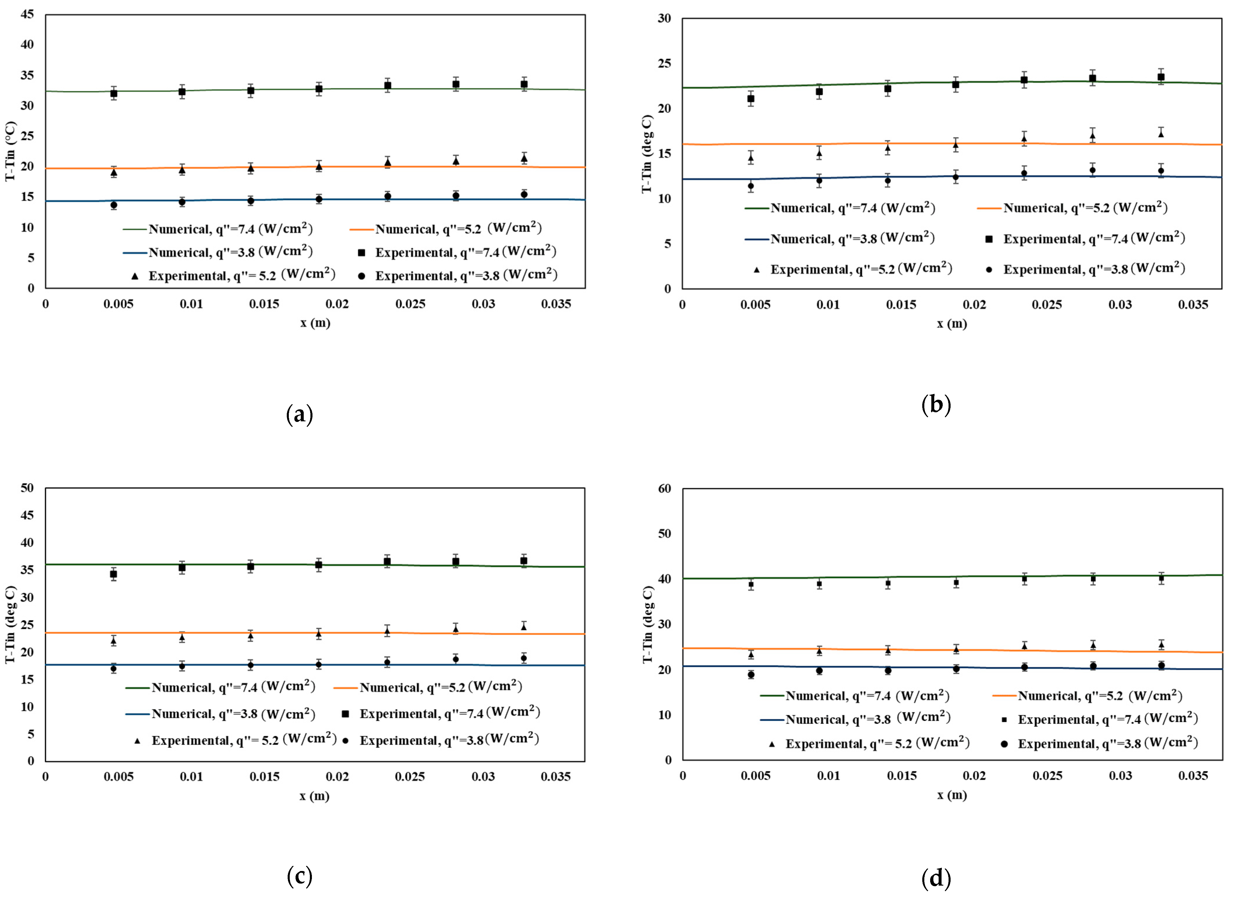
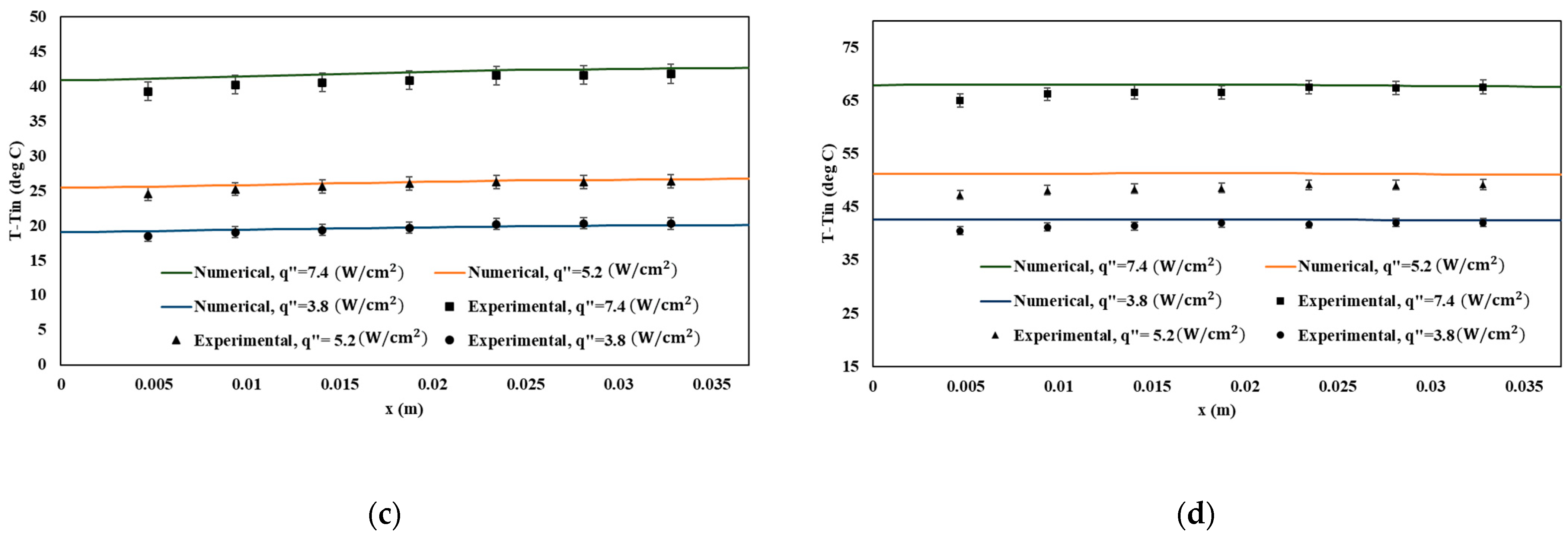
4.1. Temperature Difference Variations

The temperature difference distribution along the straight-channel heat sink was obtained experimentally and numerically. Figure 7 presents the temperature difference with inlet temperature for a straight-channel heat sink for the constant flow rate of 19.56   c m 3 / s while the heat fluxes change between 3.8 and 7.43 W/cm2 for four different channel heights. Based on Figure 7, the lowest temperature was obtained for the first thermocouple that is located at the entrance of the heat sink for all heat sinks with different channel heights. By looking at all cases, it can be found that increasing the heat flux leads to higher temperatures. With the comparison of temperature differences in Figure 7, when the flow rate is 19.56   c m 3 / s and the heat flux is 7.43 W/cm2, the highest temperature difference of the channel with 12.7 mm height is 33.58 , which increases to 36.67 °C and 40.16 °C once the height is reduced to 7 and 4 mm, respectively. Meanwhile for a channel with a height of 10 mm, the temperature difference reduces to 23.54 . The impact of changing the channel height and heat fluxes for the 13.25   c m 3 / s flow rate is illustrated in Figure 8. Like the previous case, by decreasing the channel height from 12.7 mm to 7 mm and 4 mm, the temperature difference is boosted for the 13.25   c m 3 / s flow rate and maximum 7.43 W/cm2 heat flux, with the difference that the range of temperature has become higher. Thus, the maximum temperature difference of 36.22 °C increases to 39.07 °C for the former, and the latter reaches 47.89 °C. However, a 2.7 mm decrease in the channel height caused the drop in temperature difference so that the temperature difference reached 26.22 °C for the heat sink with a 10 mm channel height. It can also be noted that the other two heat fluxes, 3.8 and 5.17 W/cm2, reveal the same temperature trend over the lower temperature range. Figure 9 presents the temperature difference variation for flow rate 6.94   c m 3 / s and three heat fluxes. Based on Figure 9a, the maximum temperature difference for the channel with a 12.7 mm height and minimum heat flux of 3.8 W/cm2 is 18.38 °C. As presented in Figure 9c,d, decreasing the channel height to 7 mm leads to a 10% rise in temperature, while for the channel with the height of 4 mm, a 44.3% temperature difference rise was obtained in comparison to the height of 12.7 mm. However, Figure 9b shows a 19.2% decrement in the temperature difference for the heat sink with a 10 mm channel height.
Figure 8 and Figure 9 compare the temperature differences for flow rates of 13.25 and 6.94   c m 3 / s , respectively. Reducing the channel height from 12.7 mm to 7 and 4 mm for all cases elevates the highest temperature difference along the heat sink. When the flow rates change from 6.94 to 19.56   c m 3 / s , the temperature along the heat sinks decreases due to increasing the coolant capacity of fluid with increasing velocity. For the channel with the height of 12.7 and 7.41 W/cm2 heat flux, when the flow rates decrease from 19.56 to 6.94   c m 3 / s , the maximum temperature increases from 33.85 °C to 40.8 °C. That means a 21.5% rise in the heat sink’s temperature.
Moreover, the temperature difference variation with changing the channel height is an important criterion that needs to be considered. Based on Figure 8a, for the channel with a height of 12.7 mm, the maximum temperature difference is 36.22 °C for the 13.25   c m 3 / s flow rate and 7.41 W/cm2 heat flux, whereas with a 2.7 mm decrement in channel heights under the same condition, the maximum temperature decreases to 26.22 °C. However, a further drop in channel height resulted in a higher temperature difference in such a way that a 5.7 mm decrease in channel height increased the temperature difference to 39.07 °C; the maximum temperature difference reached 47.89 °C with a reduction of 8.7 mm in channel height. It can be ascertained that decreasing the channel height in a straight-channel heat sink provides an open space on the top of the channel that ameliorates the heat transfer and reduces the temperature difference along the heat sink, but the height of the channel limits this enhancement. For all cases, the minimum temperature differences were obtained for the channel with a height of 10 mm.
Moreover, Figure 9a illustrates that decreasing the flow rate from 19.56 to 6.94   c m 3 / s causes a 17.7% rise in the heat sink’s temperature with the 10 mm channel height when the heat flux is equal to 5.17 W/cm2. Under the same condition, for the channel height of 10 mm, an 11.91% rise in maximum temperature is obtained by reducing the flow rate.
When the channel’s height is lowered to 7 mm, the temperature increases for all scenarios, which means decreasing channel heights deteriorates the heat transfer compared to the heights of 12.7 and 10 mm. Furthermore, it is important to mention that the results obtained on COMSOL modeling in straight-channel heat sinks agree with the experimental finding. Figure 10 presents the temperature counter for the straight heat sink with a height of 12.7 mm to compare the performance for two flow rates of 6.94 and 19.56   c m 3 / s . The heat sink performance for the channel with the 19.56   c m 3 / s flow rate is followed by the same flow rate of 6.94   c m 3 / s . The temperature rises in the direction of the flow, and the minimum temperature is obtained at the channel’s entrance. Moreover, with decreasing flow rate, the heat removal capacity of the heat sink decreases. The influence of flow rate on the temperature variation is significant.

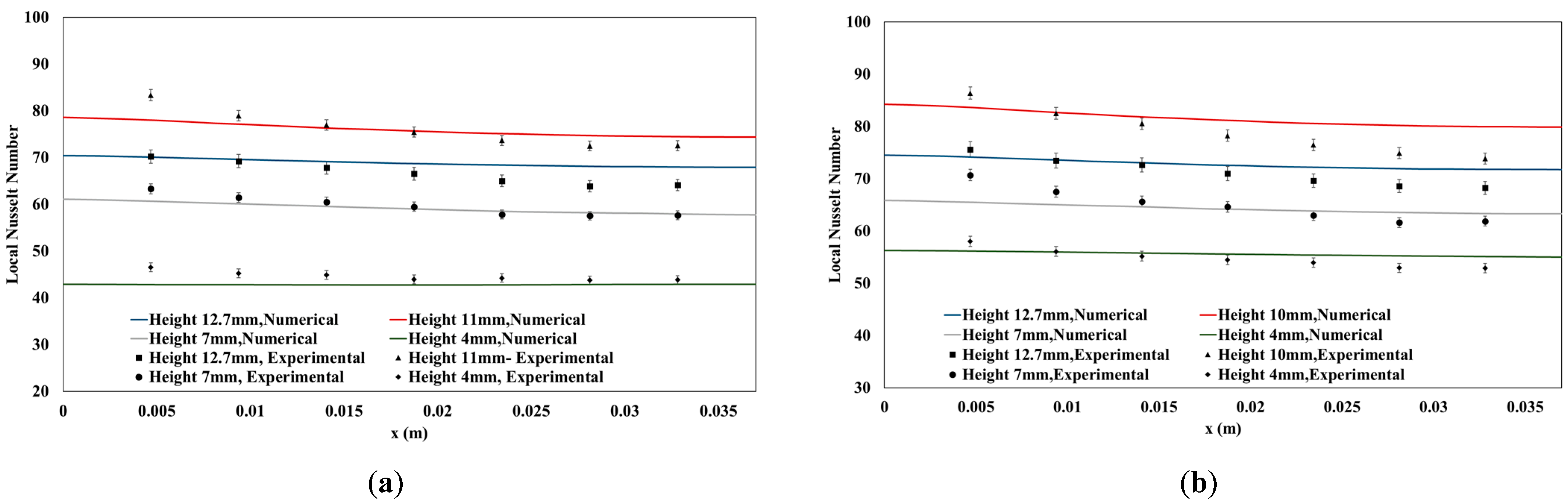
4.2. Local Nusselt Number Variation

Figure 11a presents the local Nu number for channels with heights of 12.7 and 10 mm for a maximum 7.43 W/cm2 heat flux. It should be noted that two different flow rates are compared, which are 6.94 and 13.25   c m 3 / s . As expected, there is a descending trend for the local Nu number along the heat sink for all tests. Moreover, when the flow rate increases to 19.56   c m 3 / s , the coolant capacity of the heat sink rises, which causes a higher Nusselt number than 6.94   c m 3 / s flow rates. When the flow rate increases from 6.94 to 19.56   c m 3 / s , the highest Nu number in the channel with a 10 mm height increases by 27.95%, from 89.24 to 114.19. However, by increasing the flow rate to 19.56   c m 3 / s for the channel with a height of 12.7 mm, the maximum Nu number shows a 19.42% rise and changes from 62.24 to 74.32. That result demonstrates that the impact of increased flow rates on heat transfer enhancement is more significant for channels with a height of 10 mm compared to 12.7 mm. Once the channel height is decreased from 12.7 to 10 mm, the maximum Nu number rises from 74.2 to 114.19 for the 19.56   c m 3 / s flow rate. As expected, open space above the channel enhances mixing flow and results in a higher convective heat transfer coefficient, although the convective heat transfer area reduces as channel height lowers. The maximum local Nu number is 20% higher for the channel with a height of 10 mm and a 6.94   c m 3 / s flow rate compared to the channel with a height of 12.7 mm and a 19.56   c m 3 / s flow rate. Figure 11b compares heat sinks with heights of 7 and 4 mm for flow rates of 6.94 and 19.56   c m 3 / s . When the flow rate increases to 19.56   c m 3 / s for the channel with a height of 7 mm, the maximum local Nu number increases by 23.15%, changing from 55.91 to 68.85. In comparison to a channel with a height of 7 mm, the average Nu number falls by 16.66% as the channel’s height is decreased to 4 mm. Moreover, it has also been observed that a channel with 7 mm height indeed has a higher Nu number than a channel with 4 mm height for both working fluid flow rates of 6.94 and 19.56   c m 3 / s , respectively.
To better understand the channel heights effect, the variation of local Nu number is compared for different channel heights and the minimum heat flux of 3.86 W/cm2 in Figure 12a,b. With a flow rate of 6.94   c m 3 / s , Figure 12a illustrates that the heat sink with a 10 mm channel height provides better heat transfer and possesses a higher Nu number when compared to the other heat sinks. The average Nu number of this channel is 76.2, while under the same circumstances, the average Nu number for the channel with a height of 12.7, 7, and 4 mm is 66.68, 56.68, and 44.64, respectively. Moreover, as presented in Figure 12b, increasing the flow rate to 13.25   c m 3 / s enhances heat transfer with a higher Nusselt number for all channels. By illustration, a 10 mm channel height has a 3.6% higher average Nu number when the flow rate changes to 13.25   c m 3 / s . However, the higher Nusselt number corresponds to the 10 mm channel height heat sink. The channel with a height of 4 mm yields the lowest average Nu number of 54.78. As expected, further diminishing the channel height reduces the convective heat transfer area and achieves a lower Nu number.

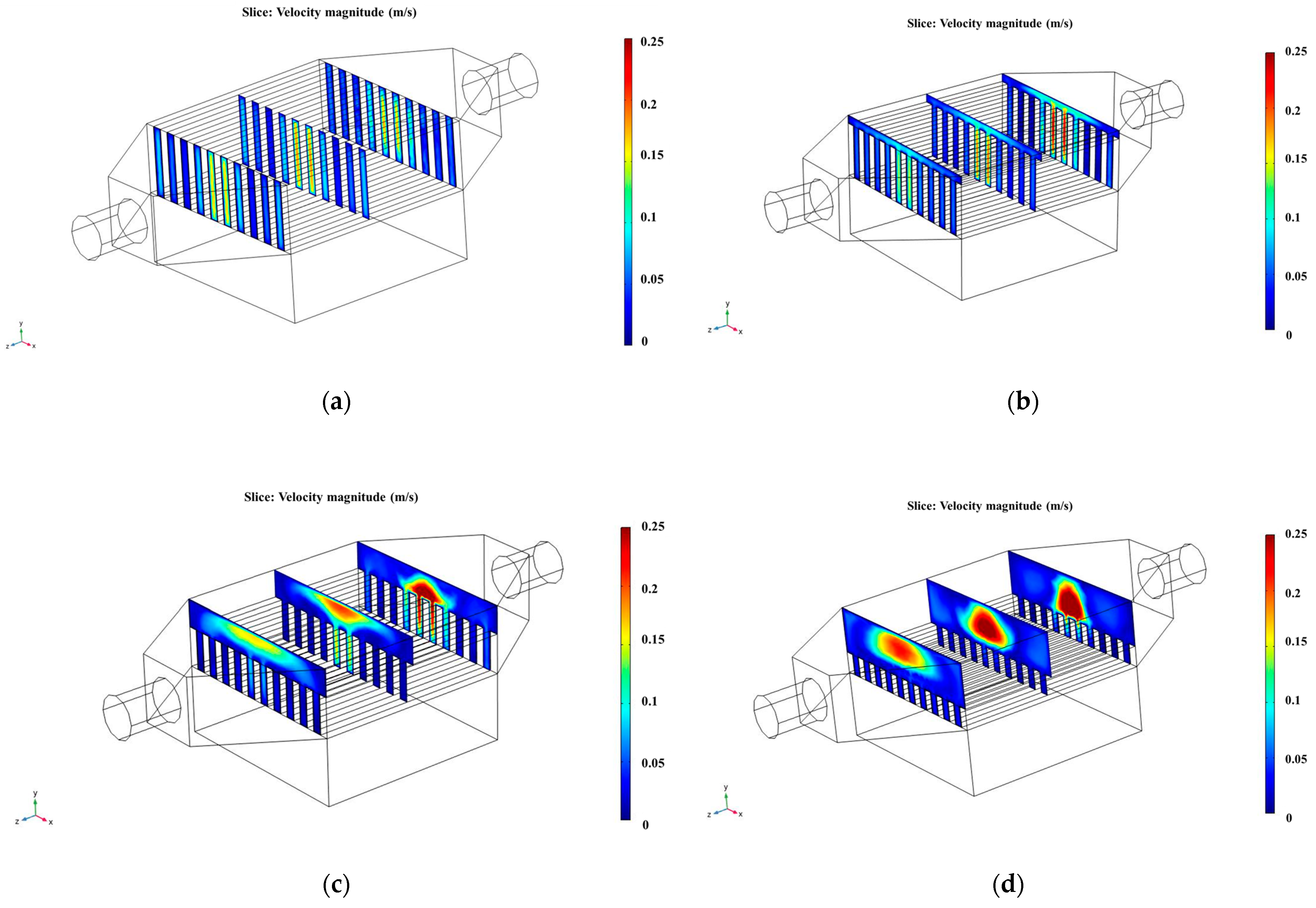
4.3. Velocity and Flow Characteristics

The velocity contours are presented in Figure 13 for X–Y planes. These planes are located along the flow direction for z equal to 0, 18.75, and 37.5 mm. The consequence of decreasing the channel height on velocity along the heat sink can be estimated by comparing Figure 13 for different channel heights. Figure 13b,c shows that the open space on the top of the channel changes the flow distribution along the heat sink. With decreasing channel height, the high-velocity area increases in the top open space of the channel. To analyze the influence of the open-top space more clearly, Figure 13c,d demonstrates that the velocity of coolant water is higher for the channel with a 7 mm height compared to 4 mm.
Moreover, the velocity is higher in the middle of the open space above the channel. The lower-height channel has low-velocity distribution along the channel area. Therefore, the heat transfer capability of coolant flow is diminished for the straight-channel heat sink with a 4 mm height. However, the comparison of Figure 13a,b reveals that decreasing the channel height from 12.7 to 10 mm grows the higher velocity area between the middle channels; meanwhile, coolant flow distributes in the open space on the top of the heat sink. On the other hand, the convective heat transfer area diminishes with decreasing channel height; hence, altering both parameters of velocity distribution and heat transfer area influences the heat sink’s thermal performance when channel heights change. Figure 14 illustrates the pressure change for different channel heights.
Figure 15 presents the streamlines for the 19.56   c m 3 / s flow rate when the channel heights are 12.7 and 10 mm. With the same condition, when the channel height decreases to 10 mm, changes in geometry lead to a change in flow behavior. Figure 15b depicts that a 2.7 mm lower height engendered more mixing flow in the diffuser section. Increasing the mixing flow is accompanied by heat transfer enhancement and more heat removal in the heat sink. Thus, coolant flow for the heat sink with a height of 10 mm possesses a higher capability for heat removal from the heated surface. Figure 16 demonstrates the velocity vectors in the X–Y plane for x between 1.96 and 2.5 mm that comprise two channel flows. These findings confirmed that the creation of an open space on the top of the channel leads to more flow mixing.

4.4. Performance Evaluation Criterion

Whereas the expense of greater pressure drop frequently goes along with the improvement in heat transfer, the performance evaluation criterion was investigated based on Equation (4) in Section 2.2 to combine the heat transfer analysis with the pressure drop. The performance of the straight-channel heat sink can be enhanced with a new design and induce high-pressure reduction. For this reason, the interaction between pressure drop and heat transfer must be considered simultaneously. Figure 17 demonstrates the PEC variation of the heat sink with a channel height equal to 12.7 mm in proportion to the heights of 10, 7, and 4 mm. As long as the PEC is more than one, lowering the channel height enhances the heat sink’s overall performance. As previously stated, lowering the channel heights reduces the heat transfer area while providing open space above the channel to create the mixing flow. As shown in Figure 17, when the height of the channel changes from 12.7 to 10 mm, the performance evaluation criterion is higher for any given flow rate. This unitless parameter has been determined for flow rates of 6.94, 13.25, and 19.56   c m 3 / s at 1.44, 1.22, and 1.34.
Additionally, with the lowest flow rate of 6.94   c m 3 / s , lowering the height of the channel from 12.7 to 7 mm results in a PEC of 1.13, whereas all other designs yield a PEC that is less than 1.0. Therefore, when the height lowers from 12.7 mm to 10 mm, it is justified to change the channel height while the height of heat remains constant at a flow rate range between 6.94 and 19.56   c m 3 / s .

5. Conclusions

This study proposes a new straight-channel heat sink design by decreasing the inside channels while maintaining the heat sink’s height constant. The temperature distribution and local Nusselt number are experimentally and numerically analyzed for various flow rates and heat fluxes with four different channel heights. In addition, the velocity distribution and streamlines are studied to assess the effect of open space above the heat sink on flow characteristics. The significant findings are summarized as follows:
  • When the height of the channel is reduced from 12.7 to 10 mm, the temperature distribution along the heat sink is diminished at all flow rates. When the maximum heat flow of 7.43 W/cm2 is combined with a heat flux of 19.56   c m 3 / s , the maximum temperature drops from 33.85 °C to 23.54 °C. Under the same circumstances, the temperature of the channels with 7 and 4 mm heights reaches 36.67 °C and 40.16 °C, respectively.
  • When the lowest heat flux and flow rate are 3.8 W/cm2 and 6.94   c m 3 / s , reducing the channel heights to 7 mm and 4 mm results in a 10% and 44.3% increase in maximum temperature compared to 12.7 mm channel heights. In contrast, reducing the height to 10 mm corresponds to a 19.2% decrease in temperature.
  • The local Nu number descends along the flow direction and has a rising trend with increasing flow rates. Increasing the flow rate from 6.94 to 19.56   c m 3 / s in a channel with a height of 10 mm yields a 27.95% growth in the maximum local Nusselt number. For channels with heights of 12.7 mm, 7 mm, and 4 mm, the exact change in flow rate has a 19.42%, 23.15%, and 16.66% influence on increasing the maximum local Nu number.
  • Decreasing the channel height to 10 mm ameliorates the heat sink’s heat transfer performance with the average Nu number of 76.2 with 6.94   c m 3 / s flow rate and 3.86 W/cm2 heat flux. However, reducing the channel height from 12.7 mm to 7 and 4 mm results in a declining Nu number; thus, the average Nu number decreases from 66.68 to 55.68 for the former and reaches 44.64 for the latter.
  • Reducing the channel height to 7 and 4 mm leads to a higher velocity area in the open space above the channel and a decreased velocity distribution between the channel area, affecting heat transfer performance. However, with a 10 mm channel height, the higher velocity distribution increases between the channel with more flow mixing in the open space above the heat sink.
  • As the channel height lowers from 12.7 to 10 mm, the highest performance evaluation criterion is attained at 1.44, 1.22, and 1.34, respectively, for flow rates of 6.94, 13.25, and 19.56   c m 3 / s . Except for the 7 mm height with a 6.94   c m 3 / s flow rate, all other designs with lower heights resulted in a PEC of less than 1.0, indicating inferior thermal performance when compared to a full-height channel with 12.7 mm height.

Author Contributions

Conceptualization, methodology, software, experiment, M.H.; supervision, writing—review and editing, M.Z.S.; review and editing, Y.B. All authors have read and agreed to the published version of the manuscript.

Funding

RGPIN-2020-07021 grant and NPRP12S-0123-190011 grant.

Data Availability Statement

Not applicable.

Acknowledgments

This publication was made possible by NPRP grant NPRP12S-0123-190011 from the Qatar National Research Fund (a member of Qatar Foundation) and The National Science and Engineering Research Council Canada(NSERC).

Conflicts of Interest

The authors declare no conflict of interest.

Nomenclature

C p Specific heat capacity (J/kg·K)
D Diameter (m)
D h Hydraulic diameter (m)
f Friction factor (dimensionless)
FBody force (N)
h Heat transfer coefficient (W/m2·K)
HHeight (m)
H c Channel height (m)
H t Heat sink height (m)
k w Water thermal conductivity (W/m·K)
L Heat sink length (m)
N u x Local Nusselt number (dimensionless)
N u ¯ Average Nu number (dimensionless)
P Pressure (Pa)
q Heat flux (W/m2)
rMeasured variable
R c Converge criterion
R e Reynolds number (dimensionless)
sIteration number
T Temperature (°C)
T b Bulk temperature (°C)
uVelocity in x-direction (m/s)
U i Combined standard uncertainty
U r Measurement error
vVelocity in y-direction (m/s)
wVelocity in z-direction (m/s)
WWidth (m)
W h Channel width (m)
W t Heat sink width (m)
X i Measured variables
Greek symbols
ρ Density (kg/m3)
μ Dynamic viscosity (Pa·s)
Subscripts
i Unit vector in x-direction
j Unit vector in y-direction
k Unit vector in z-direction

References

  1. Qu, W.; Mudawar, I. Experimental and numerical study of pressure drop and heat transfer in a single-phase micro-channel heat sink. Int. J. Heat Mass Transf. 2002, 45, 2549–2565. [Google Scholar] [CrossRef]
  2. Lin, Y.; Luo, Y.; Li, W.; Cao, Y.; Tao, Z.; Shih, T.I.P. Single-phase and Two-phase Flow and Heat Transfer in Microchannel Heat Sink with Various Manifold Arrangements. Int. J. Heat Mass Transf. 2021, 171, 121118. [Google Scholar] [CrossRef]
  3. Deng, T.; Ran, Y.; Zhang, G.; Chen, X.; Tong, Y. Design optimization of bifurcating mini-channels cooling plate for rectangular Li-ion battery. Int. J. Heat Mass Transf. 2019, 139, 963–973. [Google Scholar] [CrossRef]
  4. Hajialibabaei, M.; Saghir, M.Z. A critical review of the straight and wavy microchannel heat sink and the application in lithium-ion battery thermal management. Int. J. Thermofluids 2022, 14, 100153. [Google Scholar] [CrossRef]
  5. Tuckerman, D.B.; Pease, R.F.W. High-Performance Heat Sinking for VLSI. IEEE Electron Device Lett. 1981, EDL-2, 126–129. [Google Scholar] [CrossRef]
  6. Sidik, N.A.C.; Muhamad, M.N.A.W.; Japar, W.M.A.A.; Rasid, Z.A. An overview of passive techniques for heat transfer augmentation in microchannel heat sink. Int. Commun. Heat Mass Transf. 2017, 88, 74–83. [Google Scholar] [CrossRef]
  7. Bayomy, A.M.; Saghir, M.Z.; Yousefi, T. Electronic cooling using water flow in aluminum metal foam heat sink: Experimental and numerical approach. Int. J. Therm. Sci. 2016, 109, 182–200. [Google Scholar] [CrossRef]
  8. Lee, Y.J.; Singh, P.K.; Lee, P.S. Fluid flow and heat transfer investigations on enhanced microchannel heat sink using oblique fins with parametric study. Int. J. Heat Mass Transf. 2015, 81, 325–336. [Google Scholar] [CrossRef]
  9. Yang, X.; Wei, L.; Cao, F.; Zhang, L.; Lu, Z.; Meng, X.; Jin, L. A parametric study of laminar convective heat transfer in fractal minichannels with hexagonal fins. Int. J. Energy Res. 2020, 44, 9382–9398. [Google Scholar] [CrossRef]
  10. Peng, X.F.; Peterson, G.P. Convective heat transfer and flow friction for water flow in microchannel structures. Int. J. Heat Mass Transf. 1996, 39, 2599–2608. [Google Scholar] [CrossRef]
  11. Harms, T.M.; Kazmierczak, M.J.; Gerner, F.M. Developing convective heat transfer in deep rectangular microchannels. Int. J. Heat Fluid Flow 1999, 20, 149–157. [Google Scholar] [CrossRef]
  12. Kou, H.S.; Lee, J.J.; Chen, C.W. Optimum thermal performance of microchannel heat sink by adjusting channel width and height. Int. Commun. Heat Mass Transf. 2008, 35, 577–582. [Google Scholar] [CrossRef]
  13. Chein, R.; Chen, J. Numerical study of the inlet/outlet arrangement effect on microchannel heat sink performance. Int. J. Therm. Sci. 2009, 48, 1627–1638. [Google Scholar] [CrossRef]
  14. Wang, H.; Chen, Z.; Gao, J. Influence of geometric parameters on flow and heat transfer performance of micro-channel heat sinks. Appl. Therm. Eng. 2016, 107, 870–879. [Google Scholar] [CrossRef]
  15. Ma, Y.; Liu, C.; Jiaqiang, E.; Mao, X.; Yu, Z. Research on modeling and parameter sensitivity of flow and heat transfer process in typical rectangular microchannels: From a data-driven perspective. Int. J. Therm. Sci. 2022, 172, 107356. [Google Scholar] [CrossRef]
  16. Shang, X.S.; Li, Q.W.; Cao, Q.; Li, Z.R.; Shao, W.; Cui, Z. Mathematical modeling and multi-objective optimization on the rectangular micro-channel heat sink. Int. J. Therm. Sci. 2023, 184, 107926. [Google Scholar] [CrossRef]
  17. Jin, L.W.; Lee, P.S.; Kong, X.X.; Fan, Y.; Chou, S.K. Ultra-thin minichannel LCP for EV battery thermal management. Appl. Energy 2014, 113, 1786–1794. [Google Scholar] [CrossRef]
  18. Ismayilov, F.; Akturk, A.; Peles, Y. Systematic micro heat sink optimization based on hydrofoil shape pin fins. Case Stud. Therm. Eng. 2021, 26, 101028. [Google Scholar] [CrossRef]
  19. Shamsoddini Lori, M.; Vafai, K. Heat Transfer and Fluid Flow Analysis of Microchannel Heat Sinks with Periodic Vertical Porous Ribs. Appl. Therm. Eng. 2022, 205, 118059. [Google Scholar] [CrossRef]
  20. Shen, H.; Xie, G.; Wang, C.C. Thermal performance and entropy generation of novel X-structured double layered microchannel heat sinks. J. Taiwan Inst. Chem. Eng. 2020, 111, 90–104. [Google Scholar] [CrossRef]
  21. Plant, R.D.; Saghir, M.Z. Numerical and experimental investigation of high concentration aqueous alumina nanofluids in a two and three channel heat exchanger. Int. J. Thermofluids 2021, 9, 100055. [Google Scholar] [CrossRef]
  22. Polat, M.E.; Ulger, F.; Cadirci, S. International Journal of Thermal Sciences Multi-objective optimization and performance assessment of microchannel heat sinks with micro pin-fins. Int. J. Therm. Sci. 2022, 174, 107432. [Google Scholar] [CrossRef]
  23. Chiu, H.C.; Youh, M.J.; Hsieh, R.H.; Jang, J.H.; Kumar, B. Numerical investigation on the temperature uniformity of micro-pin-fin heat sinks with variable density arrangement. Case Stud. Therm. Eng. 2023, 44, 102853. [Google Scholar] [CrossRef]
  24. Rajalingam, A.; Chakraborty, S. Effect of shape and arrangement of micro-structures in a microchannel heat sink on the thermo-hydraulic performance. Appl. Therm. Eng. 2021, 190, 116755. [Google Scholar] [CrossRef]
  25. Yan, Y.; Xue, Z.; Xu, F.; Li, L.; Shen, K.; Li, J.; Yang, Z.; He, Z. Numerical investigation on thermal-hydraulic characteristics of the micro heat sink with gradient distribution pin fin arrays and narrow slots. Appl. Therm. Eng. 2022, 202, 117836. [Google Scholar] [CrossRef]
  26. Naqiuddin, N.H.; Saw, L.H.; Yew, M.C.; Yusof, F.; Poon, H.M.; Cai, Z.; Thiam, H.S. Numerical investigation for optimizing segmented micro-channel heat sink by Taguchi-Grey method. Appl. Energy 2018, 222, 437–450. [Google Scholar] [CrossRef]
  27. Cheng, Y.; Luo, X.; Wang, P.; Yang, Z.; Huang, J.; Gu, J.; Zhao, W. Multi-objective optimization of thermal-hydraulic performance in a microchannel heat sink with offset ribs using the fuzzy grey approach. Appl. Therm. Eng. 2022, 201, 117748. [Google Scholar] [CrossRef]
  28. Xiao, H.; Liu, Z.; Liu, W. Conjugate heat transfer enhancement in the mini-channel heat sink by realizing the optimized flow pattern. Appl. Therm. Eng. 2021, 182, 116131. [Google Scholar] [CrossRef]
  29. Chai, L.; Xia, G.D.; Wang, H.S. Numerical study of laminar flow and heat transfer in microchannel heat sink with offset ribs on sidewalls. Appl. Therm. Eng. 2016, 92, 32–41. [Google Scholar] [CrossRef]
  30. Alugoju, U.K.; Dubey, S.K.; Javed, A. 3D Transient heat transfer analysis and flow visualization study in diverging microchannel for instability mitigated two-phase flow: A numerical study. Int. J. Heat Mass Transf. 2020, 160, 120212. [Google Scholar] [CrossRef]
  31. Shen, H.; Xie, G.; Wang, C.C. Heat transfer and thermodynamic analysis by introducing multiple alternation structures into double-layer microchannel heat sinks. Int. J. Therm. Sci. 2019, 145, 105975. [Google Scholar] [CrossRef]
  32. Debbarma, D.; Pandey, K.M.; Paul, A. Numerical study on double layered micro channel heat sink with partly diverged channel in top layer. Mater. Today Proc. 2020, 45, 6542–6546. [Google Scholar] [CrossRef]
  33. Debbarma, D.; Pandey, K.M.; Paul, A. Numerical investigation on the impact of protrusions mounted on sidewalls of double layered micro channel heat sink. Mater. Today Proc. 2020, 45, 7001–7005. [Google Scholar] [CrossRef]
  34. Shen, H.; Xie, G.; Wang, C.C.; Liu, H. Experimental and numerical examinations of thermofluids characteristics of double-layer microchannel heat sinks with deflectors. Int. J. Heat Mass Transf. 2022, 182, 121961. [Google Scholar] [CrossRef]
  35. Prajapati, Y.K. Influence of fin height on heat transfer and fluid flow characteristics of rectangular microchannel heat sink. Int. J. Heat Mass Transf. 2019, 137, 1041–1052. [Google Scholar] [CrossRef]
  36. Bhandari, P.; Prajapati, Y.K. Thermal performance of open microchannel heat sink with variable pin fin height. Int. J. Therm. Sci. 2021, 159, 106609. [Google Scholar] [CrossRef]
  37. Kadam, S.T.; Kumar, R.; Abiev, R. Performance augmentation of single-phase heat transfer in open-type microchannel heat sink. J. Thermophys. Heat Transf. 2019, 33, 416–424. [Google Scholar] [CrossRef]
  38. Yin, L.; Jiang, P.; Xu, R.; Hu, H.; Jia, L. Heat transfer and pressure drop characteristics of water flow boiling in open microchannels. Int. J. Heat Mass Transf. 2019, 137, 204–215. [Google Scholar] [CrossRef]
  39. Do Nascimento, F.J.; Leão, H.L.S.L.; Ribatski, G. An experimental study on flow boiling heat transfer of R134a in a microchannel-based heat sink. Exp. Therm. Fluid Sci. 2013, 45, 117–127. [Google Scholar] [CrossRef]
  40. Plant, R.D.; Hodgson, G.K.; Impellizzeri, S.; Saghir, M.Z. Experimental and numerical investigation of heat enhancement using a hybrid nanofluid of copper oxide/alumina nanoparticles in water. J. Therm. Anal. Calorim. 2020, 141, 1951–1968. [Google Scholar] [CrossRef]
  41. Yildizeli, A.; Cadirci, S. Multi objective optimization of a micro-channel heat sink through genetic algorithm. Int. J. Heat Mass Transf. 2020, 146, 118847. [Google Scholar] [CrossRef]
  42. Tikadar, A.; Paul, T.C.; Oudah, S.K.; Abdulrazzaq, N.M.; Salman, A.S.; Khan, J.A. Enhancing thermal-hydraulic performance of counter flow mini-channel heat sinks utilizing secondary flow: Numerical study with experimental validation. Int. Commun. Heat Mass Transf. 2020, 111, 104447. [Google Scholar] [CrossRef]
  43. Kandlikar, S.G.; Garimella, S.; Li, D.; Colin, S.; King, M. Heat Transfer and Fluid Flow in Minichannels and Microchannels; Elsevier: Amsterdam, The Netherlands, 2014; ISBN 9780080983462. [Google Scholar]
  44. Coleman, H.W.; Steele, W.G. Experimentation, Validation, and Uncertainty Analysis for Engineers; John Wiley & Sons: Hoboken, NJ, USA, 2018; ISBN 978-1-119-41751-4. [Google Scholar]
  45. Bayomy, A.M.; Saghir, M.Z. Heat transfer characteristics of aluminum metal foam subjected to a pulsating/steady water flow: Experimental and numerical approach. Int. J. Heat Mass Transf. 2016, 97, 318–336. [Google Scholar] [CrossRef]
  46. Saghir, M.Z. A Novel Approach of Heat Rate Enhancement in Rectangular Channels with Thin Porous Layer at the Channel Walls. Sci 2021, 3, 42. [Google Scholar] [CrossRef]
Figure 1. The schematic diagram and picture of the experimental setup.
Energies 16 03825 g001
Figure 2. Straight-channel test pieces with the heights of 12.7, 10, 7, and 4 mm.
Energies 16 03825 g002
Figure 3. The schematic and boundary conditions of the straight-channel heat sink.
Energies 16 03825 g003
Figure 4. The schematic of the straight channel with a height of 7 mm.
Energies 16 03825 g004
Figure 5. Mesh sensitivity analysis for average Nusselt number and maximum temperature.
Energies 16 03825 g005
Figure 6. Illustration of computational mesh generation.
Energies 16 03825 g006
Figure 7. Temperature difference variation for flow rate of 19.56   c m 3 / s : (a) channel height 12.7 mm; (b) channel height 10 mm; (c) channel height 7 mm; (d) channel height 4 mm.
Energies 16 03825 g007
Figure 8. Temperature difference variation for flow rate 13.25   c m 3 / s : (a) channel height 12.7 mm; (b) channel height 10 mm; (c) channel height 7 mm; (d) channel height 4 mm.
Energies 16 03825 g008
Figure 9. Temperature difference variation for flow rate 6.94   c m 3 / s : (a) channel height 12.7 mm; (b) channel height 10 mm; (c) channel height 7 mm; (d) channel height 4 mm.
Energies 16 03825 g009aEnergies 16 03825 g009b
Figure 10. Temperature counter for straight-channel heat sink with 12.7 mm and maximum heat flux: (a) 19.56   c m 3 / s flow rate; (b) 6.94   c m 3 / s flow rate.
Energies 16 03825 g010
Figure 11. The comparison of Nusselt number along the heat sink for 7.43 W/cm2 heat flux: (a) heat sink with 12.7 and 10 mm heights and flow rates of 6.94 and 19.56   c m 3 / s ; (b) heat sink with 7 and 4 mm height and flow rates of 6.94 and 19.56   c m 3 / s .
Energies 16 03825 g011
Figure 12. The Nu number variation along the heat sink with 3.86 W/cm2 heat flux for different channel heights: (a) 6.94   c m 3 / s flow rate; (b) minimum flow rate of 13.25   c m 3 / s .
Energies 16 03825 g012
Figure 13. Velocity contour in X–Y planes for straight-channel heat sinks with indium heat flux and 13.25   c m 3 / s flow rate: (a) channel height 12.7 mm; (b) channel height 10 mm; (c) channel height 7 mm; (d) channel height 4 mm.
Energies 16 03825 g013
Figure 14. Pressure changes with flow rate for straight-channel heat sink with 12.7, 10, 7.5, and 4 mm height.
Energies 16 03825 g014
Figure 15. Streamlines for straight-channel heat sink with 19.56   c m 3 / s flow rate: (a) 12.7 mm height; (b) 10 mm height.
Energies 16 03825 g015
Figure 16. Velocity vectors along straight-channel heat sink cross-sections for the flow rate of 13.25   c m 3 / s : (a) 12.7 mm channel height; (b) 10 mm channel height.
Energies 16 03825 g016
Figure 17. Performance evaluation criterion for different flow rates and channel heights compared to the height of 12.7 mm.
Energies 16 03825 g017
Table 1. The uncertainty of measurement parameters.
ParametersComponentsUncertainty
TemperatureT-type thermocouple ± 0.75%
Flow rateDigital flow meters ± 0.44%
Nu number- ± 2.44 %
Table 2. The geometry of straight channels with varying heights.
ComponentsHeight (mm)Width (mm)Length (mm)
Heat sink12.737.537.5
Channel12.7, 10, 7, 41.8837.5
Disclaimer/Publisher’s Note: The statements, opinions and data contained in all publications are solely those of the individual author(s) and contributor(s) and not of MDPI and/or the editor(s). MDPI and/or the editor(s) disclaim responsibility for any injury to people or property resulting from any ideas, methods, instructions or products referred to in the content.

