
Wireless Battery Chargers Operating at Multiple Switching Frequencies with Improved Performance

Abstract
:1. Introduction
2. Simulation-Based Analysis of the Wireless Charger Performance
2.1. Analysis of the Conventional Wireless Charger Operating at a Single Frequency or Multiple Frequencies
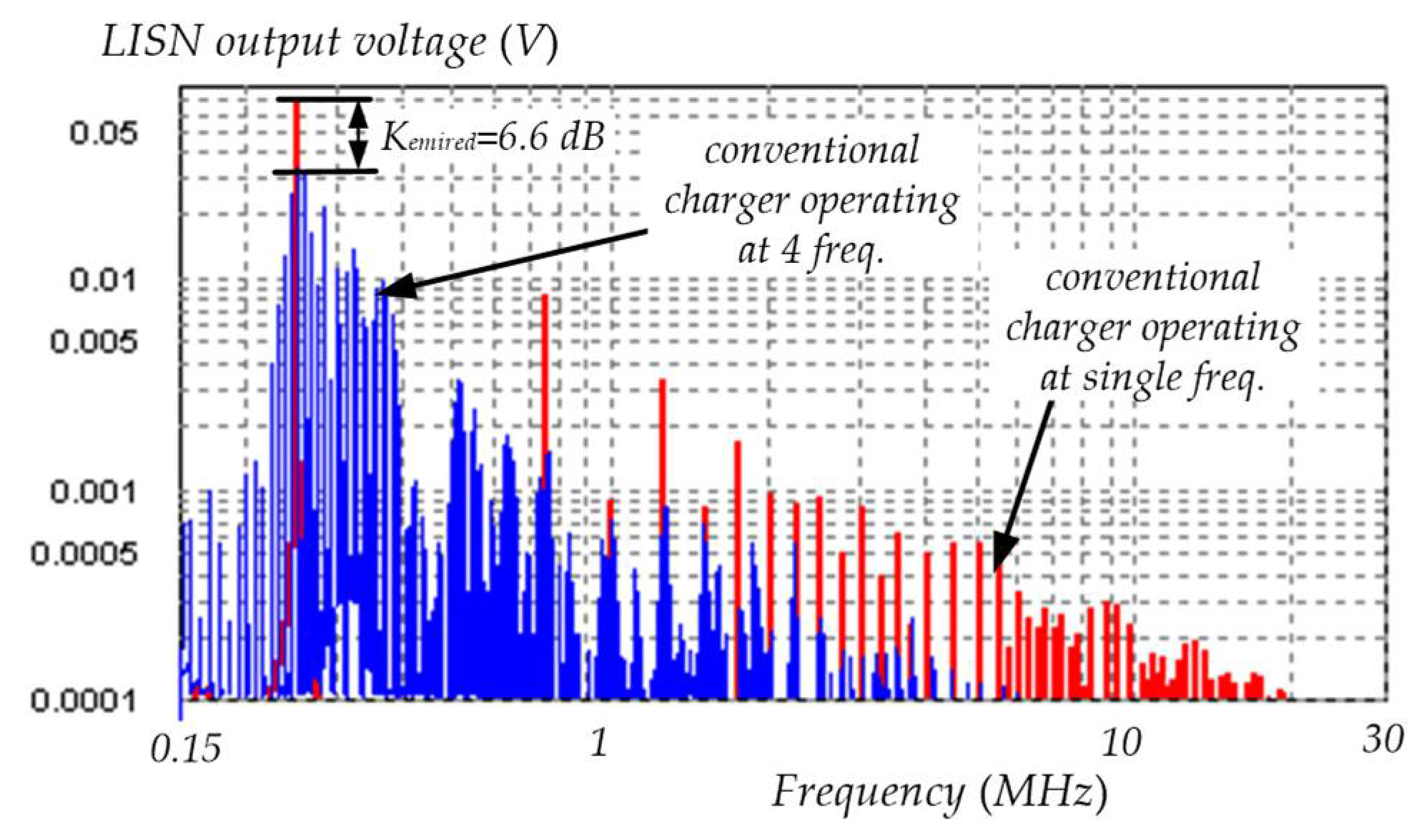
- The operation of the wireless charger at multiple frequencies leads to significant reduction in the conducted EMI. However, the coefficient of the reduction in EMI decreases as the load resistance increases. However, this may not be a problem in terms of complying with EMC standards, because at a higher Rload, EMI levels are lower.
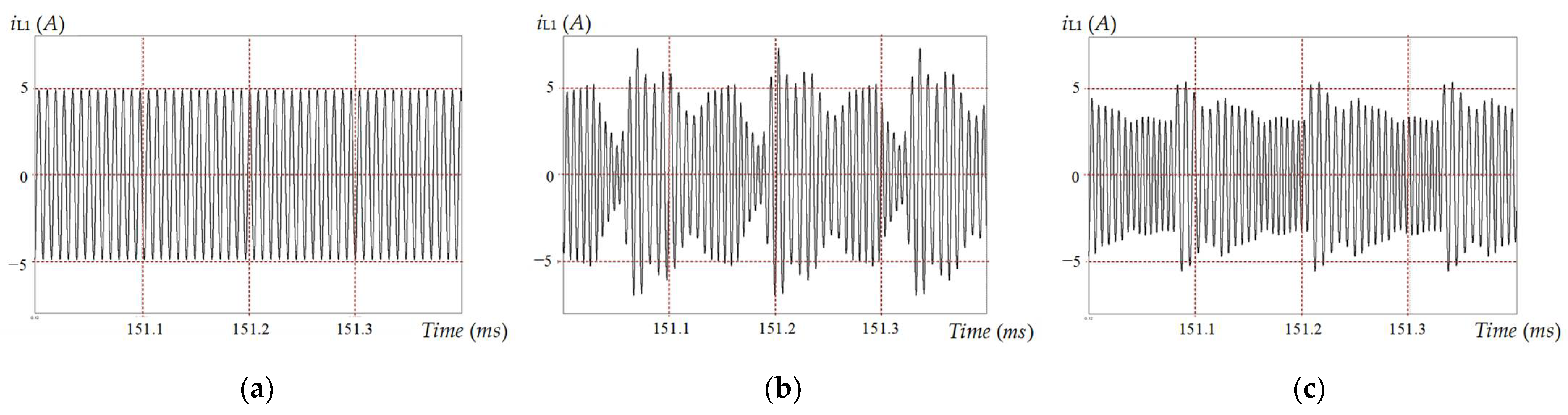
- The peak values of the currents of the transmitting coil of the conventional wireless charger operating at multiple switching frequencies are much higher (up to 50%) at a lower Rload (in CC mode and in the beginning of CV mode), but the percentage difference goes down as Rload increases.
- The peak values of the currents of the receiving coil of the conventional wireless charger operating at multiple switching frequencies are much higher (from approximately 50% in CC mode to more than 100% in CV mode at Rload > 40 Ω).
- The RMS values of the currents of the transmitting coil of both types of the conventional wireless chargers have similar values, but at a higher Rload, the conventional charger operating at multiple frequencies has moderately lower values.
- The RMS values of the currents of the receiving coil of the conventional wireless charger operating at multiple switching frequencies are moderately higher (the difference increases from 10% to 25% as Rload increases).
- The RMS values of the currents of the high-side MOSFETs of the H-bridge inverter are similar for both types of the conventional wireless chargers (at every Rload).
- The RMS values of the currents of the low-side MOSFETs of the H-bridge inverter are moderately lower for the conventional wireless charger operating at multiple switching frequencies (especially at a higher Rload).
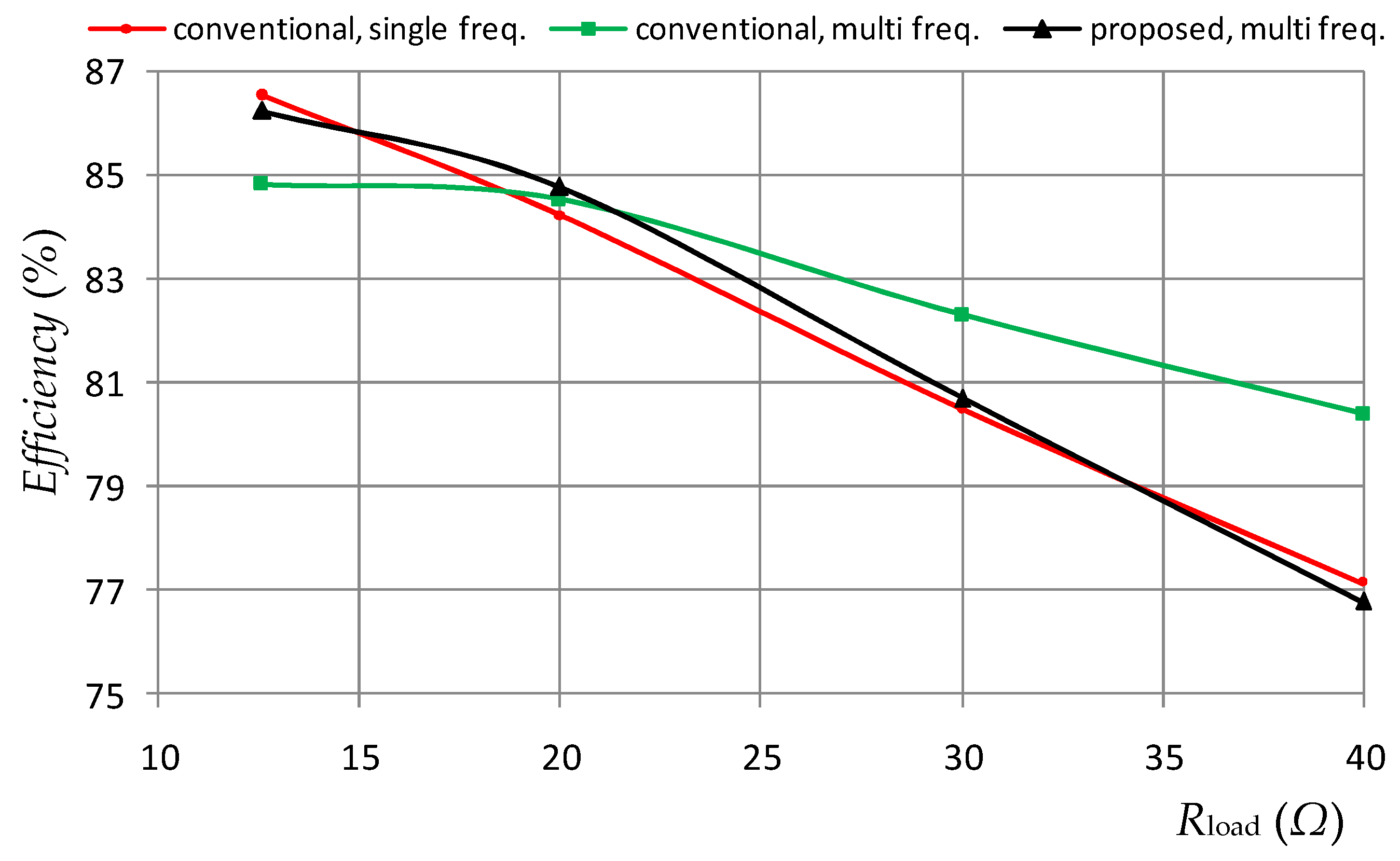
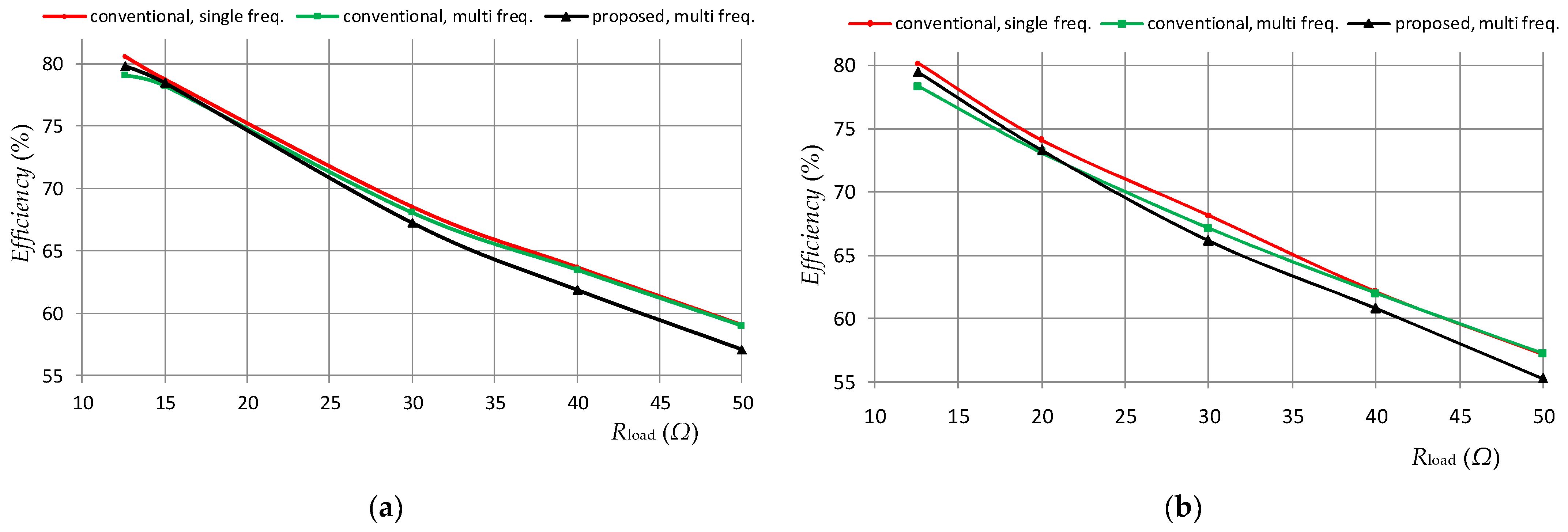
- The conventional wireless charger operating at multiple switching frequencies has noticeably lower efficiency at a lower Rload (in CC mode and in the beginning of CV mode) but noticeably higher efficiency in CV mode (when Rload > 30 Ω) than that of the wireless charger operating at a single frequency. The simulations also revealed that the difference between the efficiencies becomes even higher at lower mutual inductances in CC mode. It should be noted that the increase in the efficiency at higher load resistances may not be so noticeable in a real life, because the simulation model does not take into account the switching losses and the fact that the parasitic resistances of the components are frequency-dependent.
2.2. Analysis of the Wireless Charger Operating at Multiple Frequencies with the Proposed Control Approach and Modified Resonant Tank
3. Experiments
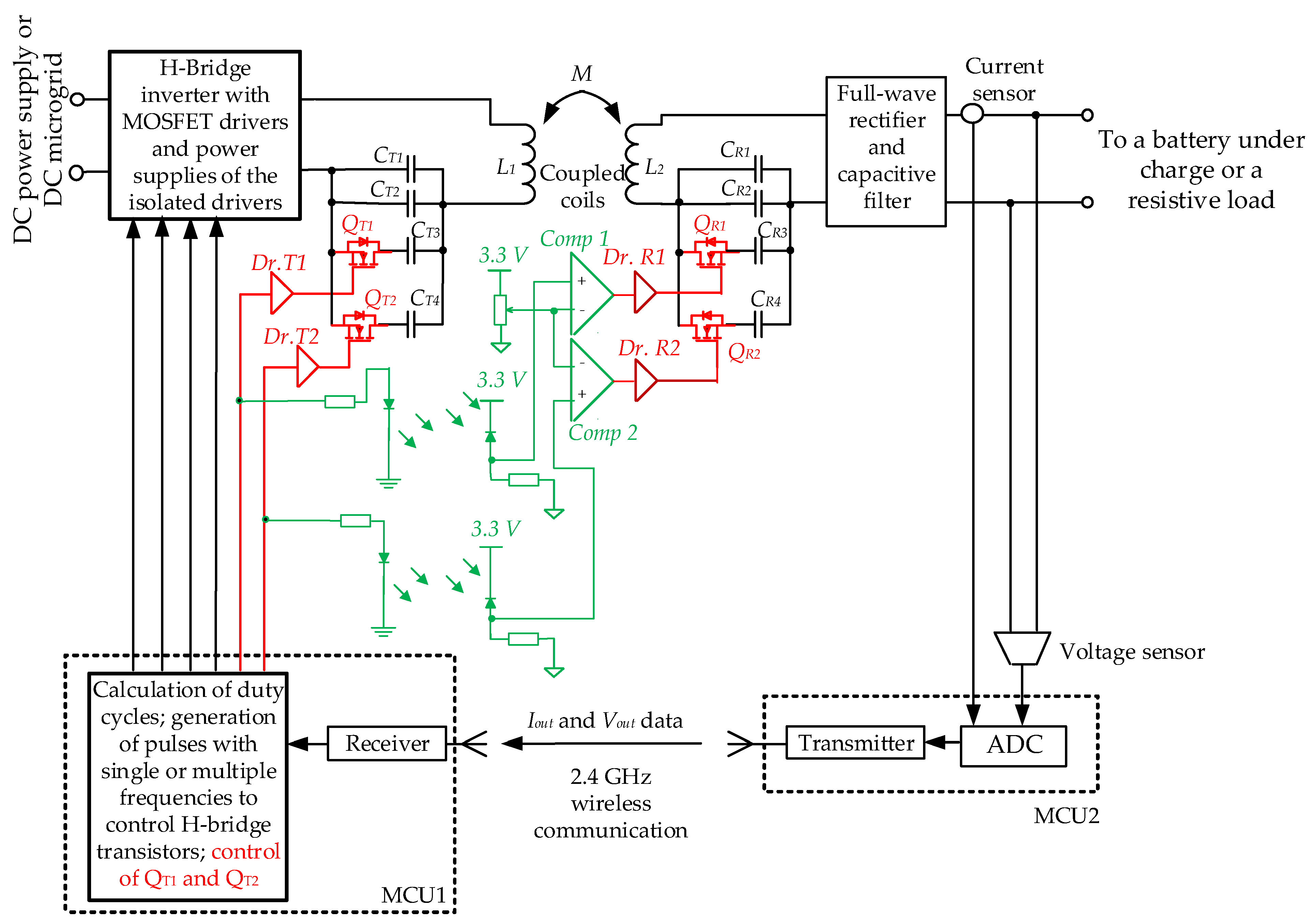
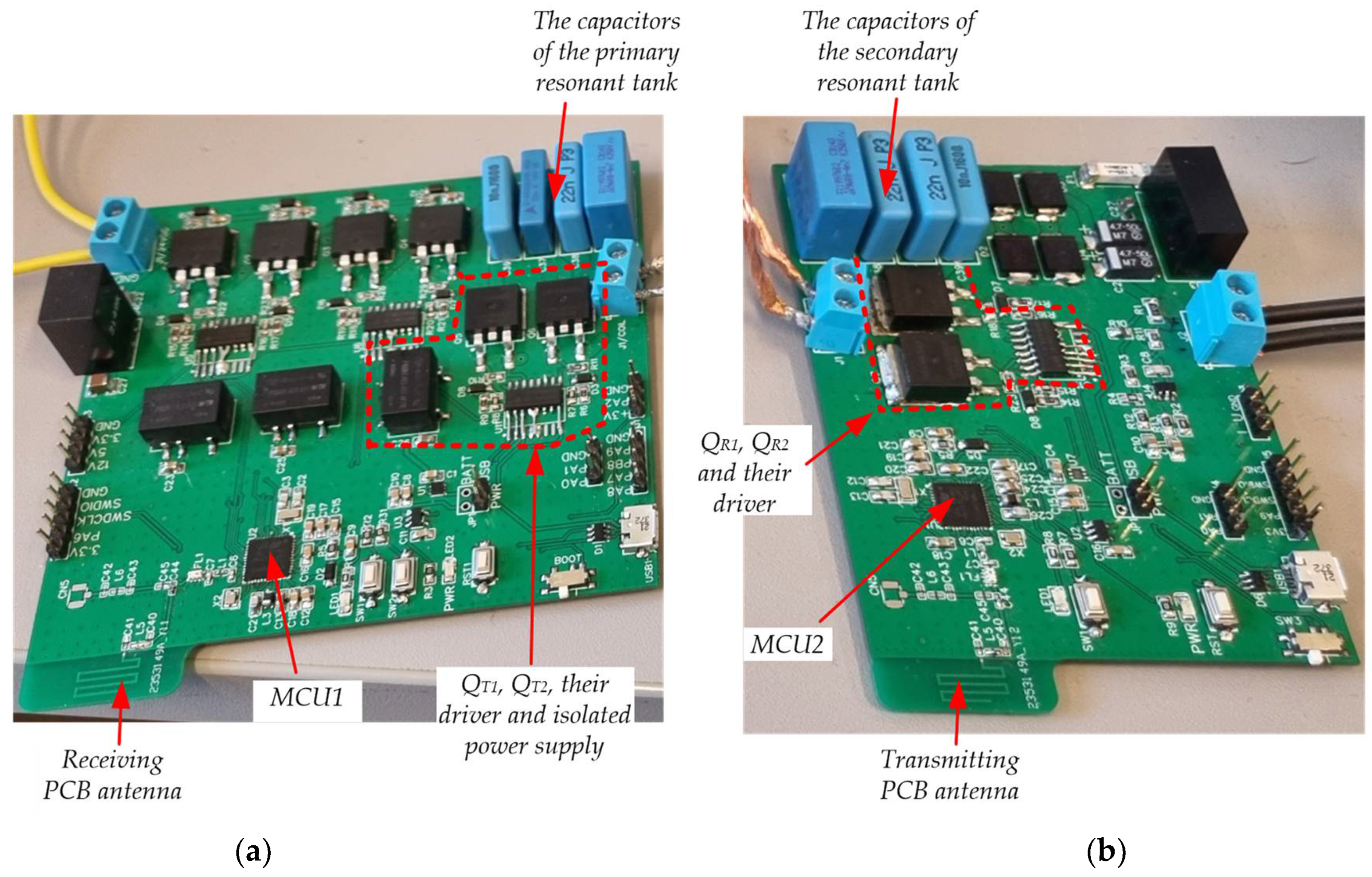
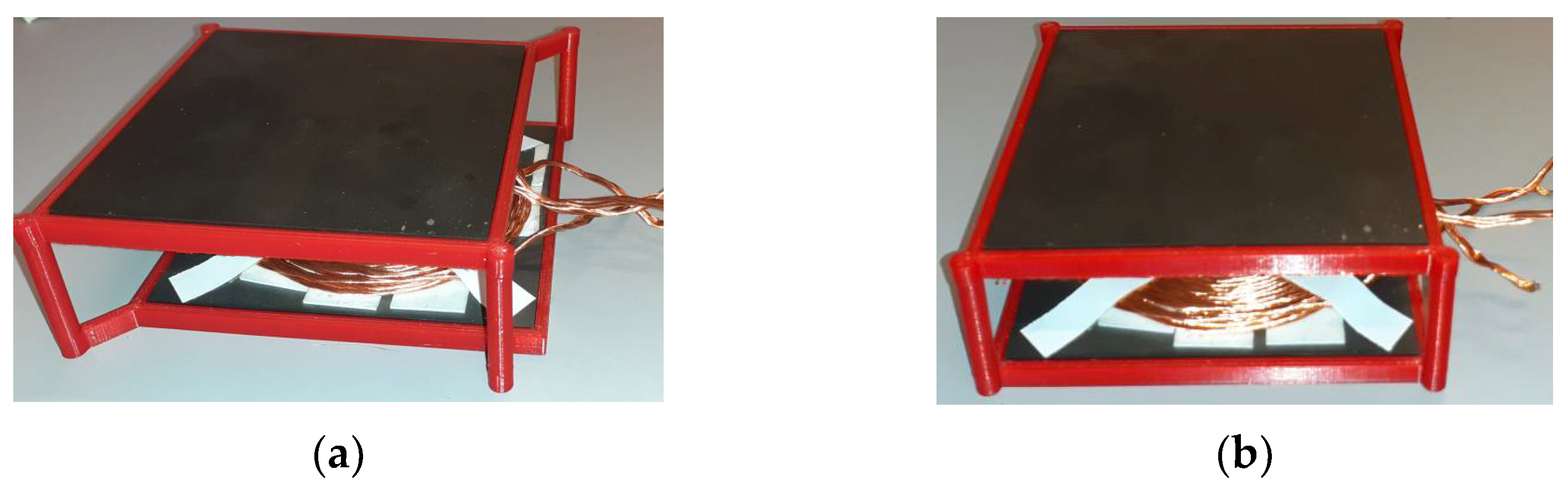
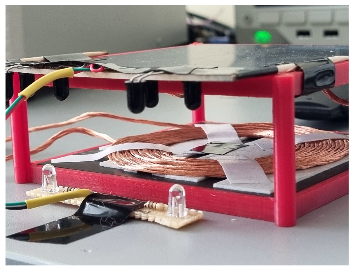
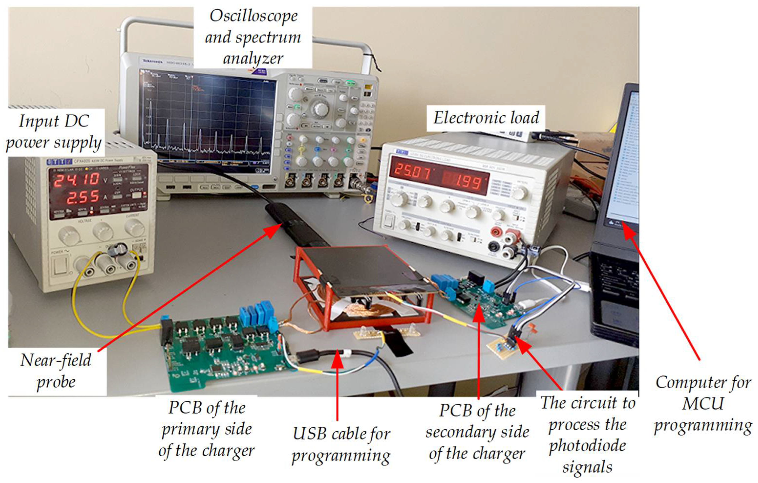
3.1. Experimental Prototype
3.2. Experimental Results and Discussion
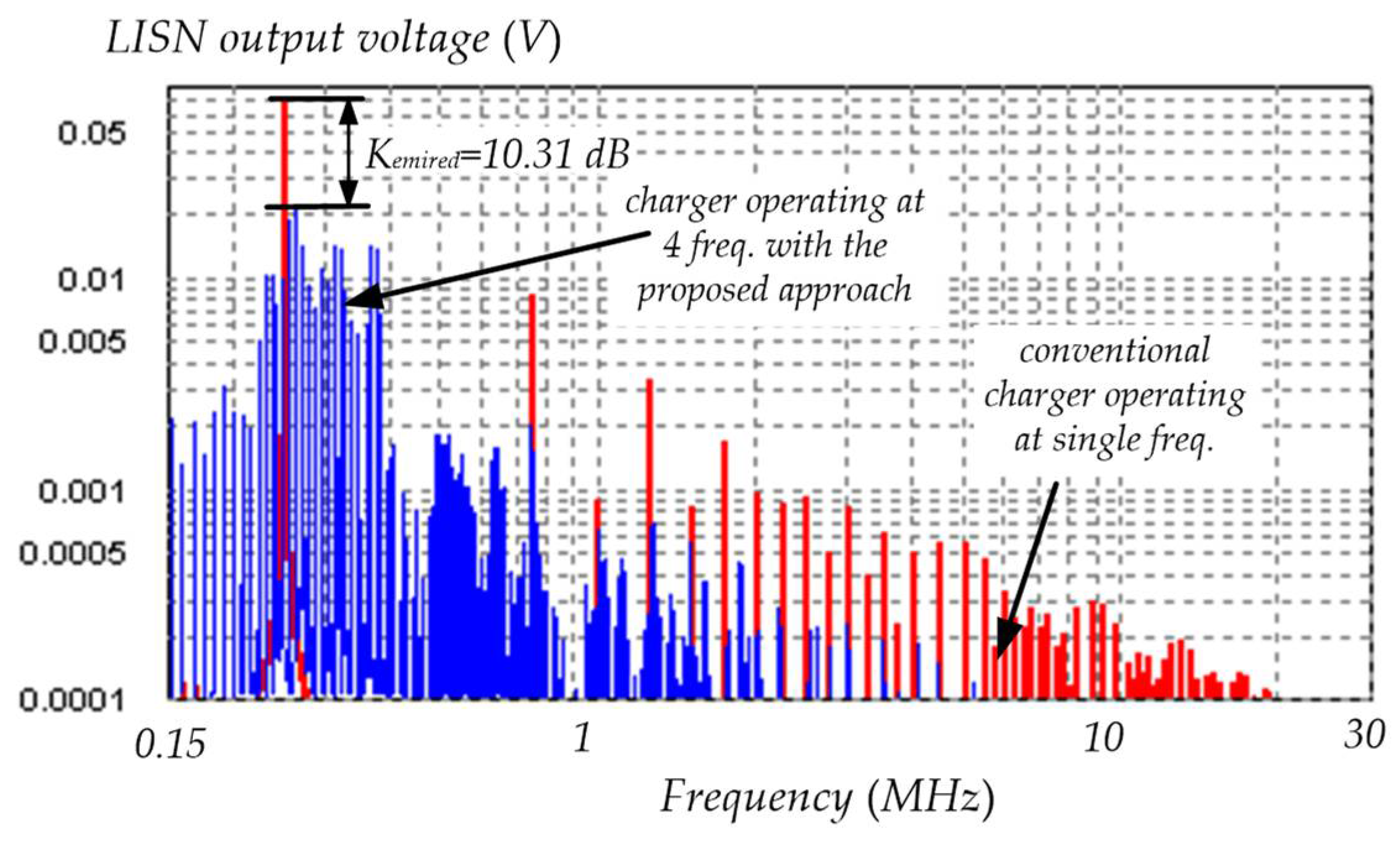
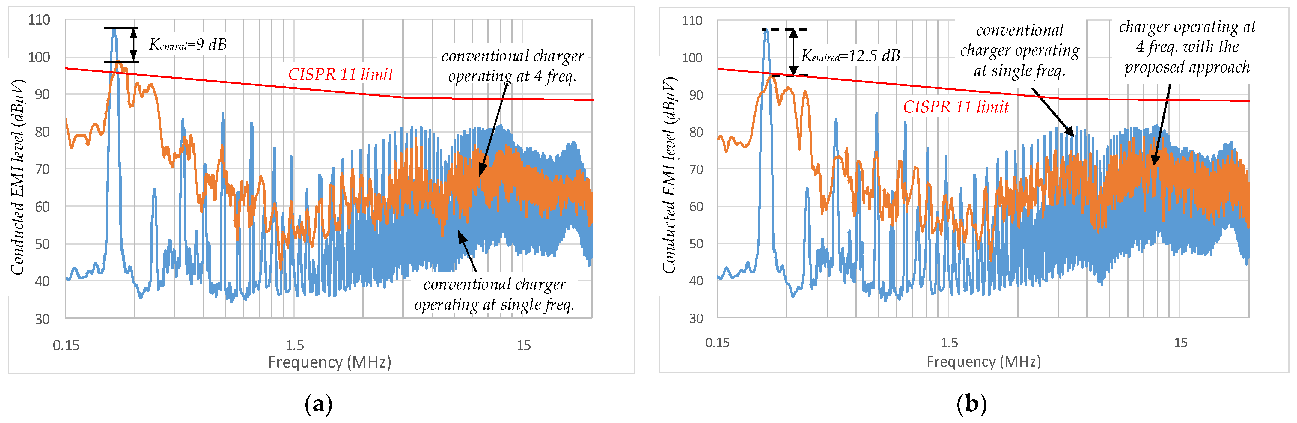
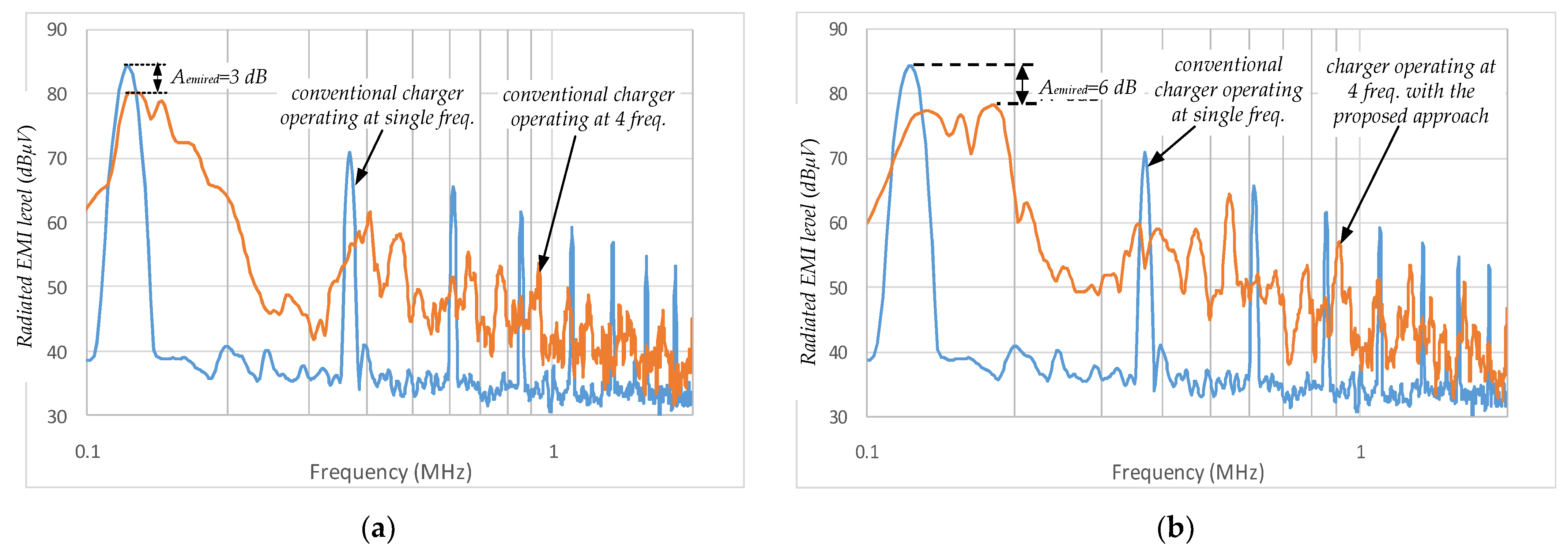
- The experimental results confirm the simulation results that the proposed approach for the improvement of the performance of the wireless charger gives much better (up to 4.1 dB higher) conducted EMI reduction coefficient at every Rload (see Table 3 and Table 4 and Figure 18). Moreover, the proposed wireless charger’s conducted EMI levels are in compliance with CISPR11 Group 1 Class A Q-peak standard limits (see Figure 18) within the whole range of Rload (EMI filter can be eliminated), but the conducted EMI of the conventional wireless charger operating at either a single or four frequencies does not comply with CISPR11 Group 1 Class A standard requirements, especially in CC mode (EMI filter still should be used). The experimental results, similar to the simulation results, also show that the difference between the conducted EMI reduction coefficients decreases as the Rload increases. However, the simulation model cannot accurately predict Kemired, mainly because we did not know the actual values of the parasitic resistances of the capacitors (especially the input capacitor) and the coils.
- The wireless charger with the proposed approach for the performance improvement also has much lower peak values of the currents of the WPT coils at a lower Rload (in CC mode and in the beginning of CV mode) than those of the conventional wireless charger operating at multiple frequencies. However, the proposed approach gives only a moderate reduction in the peak values at higher load resistances (Rload > 40 Ω). A comparison of the simulated and experimental peak values revealed that there is moderate agreement between the results (difference <10%). The peak values can be predicted with moderate accuracy.
- The wireless charger with the proposed approach for the performance improvement also has noticeably lower RMS values of the currents of the WPT coils at a lower Rload (in CC mode and in the beginning of CV mode) than those of the conventional wireless charger operating either at multiple frequencies or a single frequency. However, the RMS values of the currents of the proposed wireless charger are very similar to those of the conventional wireless charger operating at multiple frequencies at higher load resistances (Rload > 40 Ω). The experimental RMS values are in good agreement with the simulated results. The simulation model can be used for accurate prediction of RMS values of the currents of the power components.
- The experimental results (Figure 17) also confirm the simulation results that the wireless charger with the proposed approach for the performance improvement has noticeably higher efficiency (by up to 1.4%) at a lower Rload (in CC mode and in the beginning of CV mode, especially at the maximum misalignment) than that of the conventional wireless charger operating at multiple frequencies. However, in contrast to the simulation results, the experimental results show that the wireless charger with the proposed approach for the performance improvement has noticeably lower efficiency at a higher Rload (CV mode, Rload > 30 Ω) than that of the conventional wireless chargers operating at either a single or multiple switching frequencies. Moreover, the experimental results also show that the efficiency of the conventional wireless charger operating at multiple frequencies (with QT1 and QR1 “on”, but QT2 and QR2 “off”) is not noticeably higher than that of the conventional wireless charger operating at a single frequency, but the efficiencies are very similar at higher load resistances (Rload > 35 Ω). The experiments also revealed that when QT1, QR1, QT2, and QR2 are “on”, the efficiency of the conventional wireless charger operating at multiple frequencies is noticeably higher than that of the conventional wireless charger operating at a single frequency. The simulation model cannot accurately predict the efficiency because we did not know actual values of the parasitic resistances of the power components and we did not take into account the switching losses and losses in the ferrite pads.
4. Conclusions
Author Contributions
Funding
Data Availability Statement
Conflicts of Interest
References
- Li, Y.; Duan, Q.; Zou, Y. High Robustness Control for Robotic Wireless Power Transfer Systems with Multiple Uncertain Parameters Using a Virtual Buck Converter. Energies 2017, 10, 517. [Google Scholar] [CrossRef]
- AGV Navigation: Methods, Comparison, Pros and Cons—Illustrated Guide. Available online: https://www.agvnetwork.com/types-of-navigation-systems-automated-guided-vehicles (accessed on 10 April 2023).
- Mohammadpour, M.; Zeghmi, L.; Kelouwani, S.; Gaudreau, M.-A.; Amamou, A.; Graba, M. An Investigation into the Energy-Efficient Motion of Autonomous Wheeled Mobile Robots. Energies 2021, 14, 3517. [Google Scholar] [CrossRef]
- Oitzman, M. A Guide to the Latest in Mobile Robot Technology at IMTS 2018. Robotics Business Review. 11 September 2018. Available online: https://www.controleng.com/articles/mobile-platform-can-be-used-as-base-for-mobile-machining/ (accessed on 9 April 2023).
- Stepins, D.; Zakis, J.; Padmanaban, P.; Deveshkumar Shah, D. Suppression of Radiated Emissions from Inductive-Resonant Wireless Power Transfer Systems by Using Spread-Spectrum Technique. Electronics 2022, 11, 730. [Google Scholar] [CrossRef]
- Zimmer, S.; Helwig, M.; Winkler, A.; Modler, N. Modeling Electrical Conductivity of Metal Meshes for Predicting Shielding Effectiveness in Magnetic Fields of Wireless Power Transfer Systems. Electronics 2022, 11, 2156. [Google Scholar] [CrossRef]
- Suzuki, M. Conducted Emission in an 85 kHz, 50 kW WPT System with Opposite-Phase Transfer and Spread Spectrum. In Proceedings of the 2019 IEEE PELS Workshop on Emerging Technologies: Wireless Power Transfer (WoW), London, UK, 18–21 June 2019; pp. 1–4. [Google Scholar]
- Inoue, K.; Kusaka, K.; Itoh, J. Reduction in Radiation Noise Level for Inductive Power Transfer Systems using Spread Spectrum Techniques. IEEE Trans. Power Electr. 2018, 33, 3076–3085. [Google Scholar] [CrossRef]
- Stepins, D.; Sokolovs, A.; Zakis, J. Thorough Study of Multi-Switching-Frequency-Based Spread-Spectrum Technique for Suppression of Conducted Emissions from Wireless Battery Chargers. Electronics 2023, 12, 687. [Google Scholar] [CrossRef]
- Simonazzi, M.; Sandrolini, L. Conducted Emission Analysis of a Near-Field Wireless Power Transfer System. In Proceedings of the IEEE 15th International Conference on Compatibility, Power Electronics and Power Engineering (CPE-POWERENG), Florence, Italy, 14–16 July 2021; pp. 1–6. [Google Scholar]
- Lin, J.-Y.; Hsu, Y.-C.; Lin, Y.-D. A Low EMI DC-DC Buck Converter with a Triangular Spread-Spectrum Mechanism. Energies 2020, 13, 856. [Google Scholar] [CrossRef]
- Pareschi, F.; Rovatti, R.; Setti, G. EMI reduction via spread spectrum in DC/DC converters: State of the art, optimization, and tradeoffs. IEEE Access 2015, 3, 2857–2874. [Google Scholar] [CrossRef]
- Ouseph, C.; Stepins, D.; Zakis, J. Frequency-Modulated Inductive-Resonant WPT System with Improved Efficiency. In Proceedings of the 19th IEEE International Power Electronics and Motion Control Conference (PEMC2020), Gliwice, Poland, 25–29 April 2021; pp. 1–8. [Google Scholar]
- Shevchenko, V.; Pakhaliuk, B.; Zakis, J.; Veligorskyi, O.; Luszcz, J.; Husev, O.; Lytvyn, O.; Matiushkin, O. Closed-Loop Control System Design for Wireless Charging of Low-Voltage EV Batteries with Time-Delay Constraints. Energies 2021, 14, 3934. [Google Scholar] [CrossRef]
- Cho, K.; Park, W.; Hong, M.; Park, G.; Cho, W.; Seo, J.; Han, K. Analysis of Latency Performance of Bluetooth Low Energy (BLE) Networks. Sensors 2015, 15, 59–78. [Google Scholar] [CrossRef]
- Gati, E.; Kampitsis, G.; Manias, S. Variable Frequency Controller for Inductive Power Transfer in Dynamic Conditions. IEEE Trans. Power Electron. 2017, 32, 1684–1696. [Google Scholar] [CrossRef]
- Stepins, D. An improved control technique of switching frequency modulated power factor correctors for low THD and high power factor. IEEE Trans. Power Electr. 2016, 31, 5201. [Google Scholar] [CrossRef]


| Parameter | Conv. Charger Operating at one Frequency | Conv. Charger Operating at Multiple Frequencies |
|---|---|---|
| Rated output current in CC mode | 2 A | 2 A |
| Rated output voltage in CV mode | 25.2 V | 25.2 V |
| Cut-off discharge voltage | 22.2 V | 22.2 V |
| DC input voltage | 25–30 V | 25–30 V |
| Switching frequencies 1 | 126.48 kHz | f1 = 126.48 kHz |
| f2 = 138.87 kHz | ||
| f3 = 159.97 kHz | ||
| f4 = 187.54 kHz | ||
| Capacitances of the capacitors of the resonant tanks 2 | CT1 = CR1 = 4.7 nF CT2 = CR2 = 22 nF CT3 = CR3 = 22 nF CT4 = CR4 = 10 nF | CT1 = CR1 = 4.7 nF CT2 = CR2 = 22 nF CT3 = CR3 = 22 nF |
| L1 and L2 | 27 μH | 27 μH |
| Ferrite pad size | 10 × 10 cm | 10 × 10 cm |
| Distance between the coils | 2.7 cm | 2.7 cm |
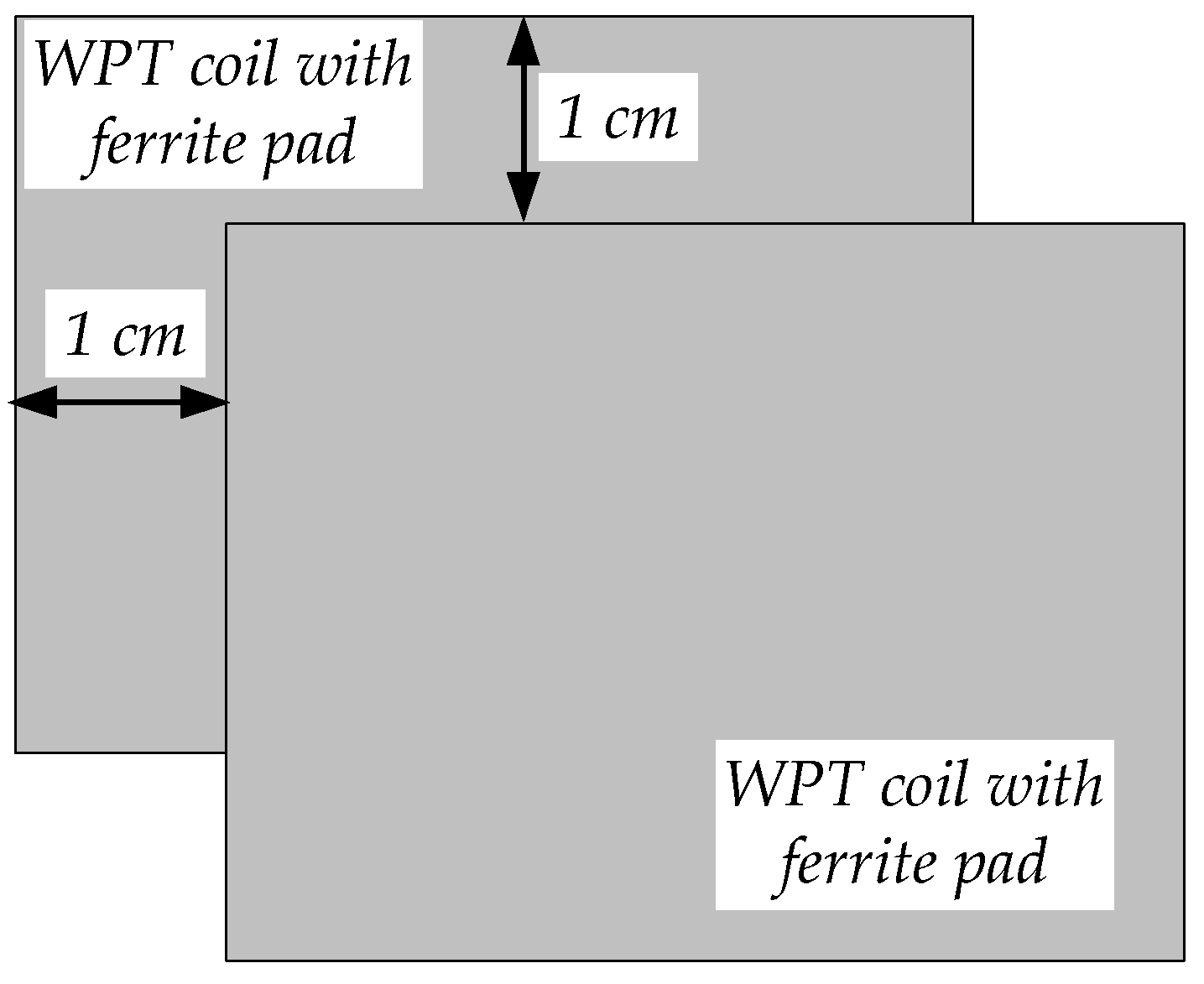
| Maximum misalignment of the coils | 1 cm | 1 cm |
| Parameter | Rload (Ω) | Classical Approach (the Charger Operates at a Single Frequency) | Classical Approach (the Charger Operates at four Frequencies w/o Modification of the Res. Tank) | Proposed Approach (the Charger Operates at four Frequencies with Modification of the Res. Tank) |
|---|---|---|---|---|
| Kemired (dB) | 12.6 | - | 6.6 | 10.31 |
| 20 | - | 5.34 | 8.36 | |
| 30 | - | 4.93 | 7.84 | |
| 40 | - | 3.9 | 7.67 | |
| IpeakL1 (A) | 12.6 | 4.87 | 7.3 | 5.24 |
| 20 | 4.79 | 6.41 | 5.23 | |
| 30 | 4.67 | 5.86 | 5.1 | |
| 40 | 4.61 | 5.29 | 4.86 | |
| IRMSL1 (A) | 12.6 | 3.53 | 3.4 | 2.9 |
| 20 | 3.49 | 3.08 | 2.87 | |
| 30 | 3.46 | 2.93 | 2.84 | |
| 40 | 3.42 | 2.8 | 2.81 | |
| IpeakL2 (A) | 12.6 | 3.32 | 5.27 | 4.59 |
| 20 | 2.55 | 3.67 | 2.98 | |
| 30 | 1.65 | 2.95 | 1.99 | |
| 40 | 1.3 | 2.71 | 1.54 | |
| IRMSL2 (A) | 12.6 | 2.27 | 2.45 | 2.24 |
| 20 | 1.47 | 1.68 | 1.47 | |
| 30 | 1.03 | 1.23 | 1 | |
| 40 | 0.79 | 0.98 | 0.77 | |
| IRMSQ1 (A) | 12.6 | 2.27 | 2.24 | 1.99 |
| 20 | 1.86 | 1.78 | 1.69 | |
| 30 | 1.55 | 1.47 | 1.42 | |
| 40 | 1.37 | 1.27 | 1.26 | |
| IRMSQ3 (A) | 12.6 | 2.7 | 2.49 | 2.1 |
| 20 | 2.95 | 2.51 | 2.32 | |
| 30 | 3.09 | 2.53 | 2.45 | |
| 40 | 3.14 | 2.55 | 2.51 |
| Parameter | Rload (Ω) | Classical Approach (the Charger Operates at a Single Frequency) | Classical Approach (the Charger Operates at four Frequencies w/o Modification of the Res. Tank) | Proposed Approach (the Charger Operates at four Frequencies with Modification of the Res. Tank) |
|---|---|---|---|---|
| Kemired (dB) | 12.6 | - | 10.1 | 14.2 |
| 15 | - | 9.3 | 12.06 | |
| 30 | - | 8.48 | 12.02 | |
| 40 | - | 8.07 | 10.68 | |
| 50 | - | 7.92 | 8.99 | |
| IpeakL1 (A) | 12.6 | 4.57 | 6.15 | 4.74 |
| 15 | 4.44 | 6.12 | 4.62 | |
| 30 | 4.38 | 4.97 | 4.6 | |
| 40 | 4.36 | 4.88 | 4.58 | |
| 50 | 4.3 | 4.56 | 4.49 | |
| IRMSL1 (A) | 12.6 | 3.28 | 3.19 | 2.69 |
| 15 | 3.24 | 3.06 | 2.68 | |
| 30 | 3.21 | 2.7 | 2.65 | |
| 40 | 3.19 | 2.66 | 2.65 | |
| 50 | 3.17 | 2.6 | 2.55 |
| Parameter | Rload (Ω) | Classical Approach (the Charger Operates at a Single Frequency) | Classical Approach (the Charger Operates at four Frequencies w/o Modification of the Res. Tank) | Proposed Approach (the Charger Operates at four Frequencies with Modification of the Res. Tank) |
|---|---|---|---|---|
| Kemired (dB) * | 12.6 | - | 9.01 | 12.46 |
| 20 | - | 8.89 | 11.73 | |
| 30 | - | 8.22 | 10.85 | |
| 40 | - | 7.93 | 10.12 | |
| 50 | - | 7.31 | 9.57 | |
| Aemired (dB) ** | 12.6 | - | 3.83 | 5.71 |
| 20 | - | 3 | 6.03 | |
| 30 | - | 2.75 | 6.62 | |
| 40 | - | 2.98 | 6.87 | |
| 50 | - | 3.27 | 6.84 | |
| IpeakL1 (A) | 12.6 | 5.24 | 6.95 | 5.24 |
| 20 | 5.12 | 6.12 | 5.17 | |
| 30 | 5.08 | 5.54 | 5.15 | |
| 40 | 5.06 | 5.51 | 5.17 | |
| 50 | 5.03 | 5.37 | 5.12 | |
| IRMSL1 (A) | 12.6 | 3.58 | 3.44 | 2.91 |
| 20 | 3.48 | 3.04 | 2.85 | |
| 30 | 3.45 | 2.91 | 2.87 | |
| 40 | 3.44 | 2.85 | 2.86 | |
| 50 | 3.42 | 2.79 | 2.86 |
Disclaimer/Publisher’s Note: The statements, opinions and data contained in all publications are solely those of the individual author(s) and contributor(s) and not of MDPI and/or the editor(s). MDPI and/or the editor(s) disclaim responsibility for any injury to people or property resulting from any ideas, methods, instructions or products referred to in the content. |
© 2023 by the authors. Licensee MDPI, Basel, Switzerland. This article is an open access article distributed under the terms and conditions of the Creative Commons Attribution (CC BY) license (https://creativecommons.org/licenses/by/4.0/).
Share and Cite
Stepins, D.; Sokolovs, A.; Zakis, J.; Charles, O. Wireless Battery Chargers Operating at Multiple Switching Frequencies with Improved Performance. Energies 2023, 16, 3734. https://doi.org/10.3390/en16093734
Stepins D, Sokolovs A, Zakis J, Charles O. Wireless Battery Chargers Operating at Multiple Switching Frequencies with Improved Performance. Energies. 2023; 16(9):3734. https://doi.org/10.3390/en16093734
Chicago/Turabian StyleStepins, Deniss, Aleksandrs Sokolovs, Janis Zakis, and Ouseph Charles. 2023. "Wireless Battery Chargers Operating at Multiple Switching Frequencies with Improved Performance" Energies 16, no. 9: 3734. https://doi.org/10.3390/en16093734