1. Introduction
Geothermal energy is the thermal energy contained in our planet, the Earth. Warm and hot fluids can be extracted from underground in a wide range of temperatures and flows. The demand for this energy is growing worldwide since it is recognized as a valuable resource that can be both inexpensive and environmentally friendly. The utilization of geothermal energy is divided into two groups based on the temperature of the geothermal resource: direct and indirect use. Direct use of geothermal heat without further conversion into other types of energy can be seen, for example, in balneology (e.g., treatment, rehabilitation, bathing) or in industry (e.g., agriculture, food industry). Indirect use is, for example, through geothermal power plants to generate electricity, or space heating and cooling through heat pumps.
While geothermal technologies for electricity generation usually produce very low levels of greenhouse gas emissions, this is mainly related to specific tectonic regions. Therefore, geothermal technologies in these areas play an important role in the realization of targets in energy security, economic development, and mitigating climate change. Worldwide geothermal heat production accounts for 164.6 TWh per year with a capacity of 70.9 GW. About a third of the installed capacity is in Europe [
1]. The top five countries in terms of installed capacity for direct use without geothermal heat pumps are China, Turkey, Japan, Iceland, and Hungary, accounting for 76.0% of the global capacity.
At the end of 1994, global installed thermal capacity for direct use was reported to be 8664 MWt. However, Lund and Boyd [
2] estimated that by the end of 2014, the worldwide installed thermal capacity had increased to 70,885 MWt. The same authors stated that by the end of 2019, the installed capacity was 105,107 MWt [
1], which means an almost 50% increase in only five years. This represents a rapid increase in installed thermal capacity over these 25 years, demonstrating the global interest and growth in the use of geothermal energy [
3]. However, geothermal water, due to its high temperature, may be heavily mineralized with chloride, sulfide, boron, mercury, arsenic, and other heavy metals, and contains a large amount of heat. Therefore, the used installations must be made of carefully selected materials. The content of dissolved minerals also makes them susceptible to fouling. The corrosion and fouling of heat transfer surfaces and pipelines caused by geothermal water is one of the major obstacles of efficient utilization of geothermal energy [
4].
Hot water springs have been used for healing and regeneration since ancient times. Geothermal sources have been observed both as a therapeutic factor, due to their temperature and chemical composition, and as a source of energy for heating and cooling facilities where geothermal water is already used for therapeutic and wellness purposes [
5]. The water management in a spa is highly dependent on the composition, flow, and temperature of the water, but in any case, it must be managed very sensitively to preserve its unique hydrogeological properties.
The data on geothermal energy utilization for bathing and swimming are the most difficult to collect and quantify. There are 88 countries that use geothermal energy, and 53 of these countries have spas and resorts with geothermally heated swimming pools, including balneology, the treatment of illnesses with water, but many never regulate the water flow, even at night when the pool is closed. The largest reported annual energy consumption for bathing and swimming comes from China, Japan, Turkey, Brazil, and Mexico, accounting for 79.5% of annual consumption [
1].
Until 1949, each spa needed to have its own evaporation tower to cool the incoming hot geothermal water to a temperature below 43 °C, a temperature that human skin can usually tolerate. In that year, the first air-cooled and tap water-cooled heat exchangers were installed to supply cooled water to the system. Thus, the spa received two water supplies: a “hot” water supply at 62 °C and a “cold” water supply at 32 °C [
6]. If the geothermal water is at a higher temperature, then some kind of cooling by aeration or in a retention pond is needed to lower the temperature. In order to maintain the chemical composition, it is not appropriate to simply dilute the water.
In the Czech Republic, the utilization of geothermal energy is mostly limited to low-enthalpy sources using heat pumps. There are only a few cases of direct use of low-temperature resources, which is limited to balneological (prevention, treatment, and rehabilitation) or recreational facilities (bathing and swimming pools). The direct use of medium or high temperature sources for electricity or heat production does not occur [
7]. The use of geothermal energy in areas of low enthalpy is possible with an EGS (enhanced geothermal system), which uses a system of two boreholes connected by an artificially expanded rock volume that provides permeability to heat cold water injected into one of the boreholes and produced in the other. A study by Šafanda et al. [
8] examined a geothermal borehole that was drilled with the idea of constructing a geothermal heat plant. It reports that the equilibrium temperature at a depth of 1.8 km is 57.5 °C, which combined with the thermal properties of the rock gives a heat flux of between 73 and 82 mW/m
2. The average heat flux from the continental crust is 57 mW/m
2 and from the oceanic crust is 99 mW/m
2 [
9]. In addition, the direct use of groundwater geothermal heat pumps for heating individual buildings and a few district heating systems can be found in sporadic cases in large urban areas or agglomerations. The estimated capacity for the Czech Republic is 324.5 MWt [
1]. The most famous thermal spring is in Carlsbad (Karlovy Vary), with temperatures in excess of 70 °C. At the regional level, thermal springs are closely linked to the freshwater cycle [
10]. It is estimated that thermal springs first emerged in this area around 230,000 years ago. Volcanic activity has led to release of CO
2 and has resulted in geothermal water enriched in bicarbonates, sulphates, and chlorides containing gaseous and dissolved CO
2 [
11].
A versatile and efficient way to use these geothermal resources is to combine their energy potential with the healing properties of the temperature and chemical composition of the water. It is clear that thermomineral water (TMW) must be cooled down before it can be used for balneological treatment. In spa facilities that are, for example, limited in space or located in historic buildings, it is not possible to simply store geothermal water in storage tanks or on the roof and wait for it to cool down. An effective technological solution must be found to reduce the temperature of the water. However, as this water is a source of heat, it would be advisable to use this heat and not waste it. Therefore, the object of this research is to carry out a search for possible solutions for cooling the water and using the waste heat and, subsequently propose a solution and apply it to a real spa operation in Carlsbad, Czech Republic. Based on the specified operating parameters and technical constraints, a suitable technology will be selected and a pilot unit will be designed and verified in at least six months of live operation. The secondary objective of the study is (a) to evaluate the possibilities of using waste (geothermal heat) in the full operation and (b) to carry out a technical and economic evaluation of the integration of the cooling technology into the operation of the balneological facility. The authors are not aware of any articles or studies that deal with the cooling of the specific mineral water from Carlsbad, including the use of released heat for balneological purposes. The novelty of this topic is confirmed by the conducted research presented in more detail in
Section 3.
2. Materials and Methods
The methodological procedure includes a literature search, its evaluation, and an application of the proposed solution to build a pilot unit and evaluate its operation. A literature search was conducted on fouling-prone technologies. Scopus database was used for the literature search. The following keywords were used to obtain the most relevant results:
geothermal (water);
mineral (water);
hydrothermal (water);
hot spring;
cooling;
balneology;
CaCO3;
scale formation.
From the core set of publications (higher tens), the final sources of literature that are relevant and at the same time do not overlap in content with
Section 1 were then selected. This set was supplemented by selected literature referring to industries whose affinity lies in the processing of liquid raw materials with high mineralization and/or a tendency to form deposits (food processing, seawater processing).
Based on the search, applicable technologies were identified, and the most appropriate ones were selected. This selection was made on the basis of several qualitative criteria that are relevant to the problem (
Section 3.3).
Based on the selection, the design of the pilot unit was then carried out. The design was made considering the technical constraints in the specific balneological facility (
Section 4.1) and was based on material and energy balances and on the experience of the authors and the cooperating industrial partner (manufacturer). The pilot unit was equipped with measuring equipment in order to collect data for continuous monitoring and subsequent evaluation of the pilot operation (
Section 4.2). In particular, it was evaluated whether it fulfilled the required function and whether there was any evidence of fouling (
Section 5.1).
The pilot unit was installed in a real spa resort. First, commissioning and several test runs were performed to verify that the pilot unit was fully functional and providing the required data. Subsequently, an operations manual was compiled and provided to the operator. A six-month pilot phase was then conducted, which provided data for basic statistical processing. The last part of the research was focused on a techno–economic evaluation, which serves as a basis for decision-making (
Section 5.2).
3. Literature Overview and Assessment of Cooling Technologies
In this chapter, the composition of spring waters from the Carlsbad region is presented and basic information about CaCO3 scaling is given. A brief overview of cooling technologies is also discussed in the context of spring waters. At the end of this chapter, an assessment of cooling technologies is provided.
3.1. Thermal Mineral Water Composition
Thermal mineral waters are formed in areas where groundwater is allowed to descend to the necessary depth and then rapidly ascend. Geothermal waters are characterized by a high concentration of dissolved solids and dissolved CO
2 content. Typical substances in these waters are Na, Mg, Ca, Fe, Cl
−, SO
42−, HCO
3−, NO
2−, or CO
2 (see typical chemical composition in
Table 1). In this study, we will discuss water of an Na
+–HCO
3−–SO
42−–Cl
− type because this type of water is typical for the thermal spring of “Vřídlo”, located in the Carlsbad region. The thermal spring of “Vřídlo” produces 33 L/s of thermal water (maximum temperature 73.4 °C) with an average concentration of total dissolved solids of approximately 6.4 g/L [
12]. During surface discharge, the chemical composition of mineral waters changes due to temperature changes and decompression, especially as dissolved gases (CO
2) escape. The escape of CO
2 from the water disturbs the calcium–carbonate balance and leads to the precipitation of calcium carbonate. The calcium–carbonate balance is an important chemical balance in hydrochemistry. If the concentration of free CO
2 in the water is higher than the equilibrium concentration, excess CO
2 will make the water aggressive and dissolve CaCO
3; on the other hand, if the concentration of free CO
2 is lower than the equilibrium concentration, precipitation and deposition of calcium carbonate will occur [
13]. Calcium carbonate is usually precipitated in the form of aragonite or calcite from the Carlsbad thermal springs.
Generally, CaCO
3 precipitation and deposition is a multistep process that is influenced by several factors such as solution supersaturation, pH value (linked with partial pressure of CO
2), temperature, presence of other salts and ions, flow velocity, and surface characteristics [
15]. One of the most important factors influencing the formation of this deposit is the pH value. As the pH increases, bicarbonate is converted to carbonate, which increases the potential for calcium carbonate formation. Andritsos and Karabelas [
16] found that increasing the pH from 8.8 to 10 increased CaCO
3 deposition from 2 to 12 mg∙cm
−2 in just 2 h. In most cases, heating results in the release of carbon dioxide molecules, causing the pH to rise [
17]. It was found that the pH value affects calcium carbonate deposition to a greater extent than temperature, with an increase in pH from 7 to 8 having a five-fold greater effect on scale precipitation than an increase in temperature of 70 °C [
15]. The effect of temperature is not as significant compared to pH, but for calcium carbonate deposits, the precipitation potential increases with increasing surface temperature and increases exponentially at temperatures above 60 °C. The effect of temperature on CaCO
3 solubility is shown in
Figure 1 [
18]. Another influencing factor is the flow velocity. During media flow, shear forces have a direct effect on the settling velocity, strength, and adhesion of the deposit and the removal of contamination on the heat transfer surface. Several studies have investigated the effect of flow velocity on the scaling of CaCO
3 [
19,
20,
21,
22]. In general, it can be concluded that higher flow velocities reduce scaling.
Scaling can be reduced mainly by chemical and physical methods. As the potential for CaCO
3 scaling is influenced by pH, one of the options is to control the pH by adding mineral acids such as sulfuric, hydrochloric, or citric acid. Another effective method is the addition of antiscalants (e.g., condensed polyphosphates, organophosphates, and polyelectrolytes), which can slow down or reduce the precipitation and sedimentation of CaCO
3 [
15]. A common method of reducing CaCO
3 scaling is ion exchange which removes all hardness ions (Ca
2+, Mg
2+, etc.) and replaces them with univalent ions (Na
+, H
+). However, these methods alter the chemical composition of the water, which is not permitted for spring waters used for balneological treatments. Physical methods include the use of magnetic, electrolytic, or electronic devices [
15]. Additionally, the scaling can be influenced by physical characteristics of the surface material (surface roughness) or by hydrodynamic conditions (flow velocity). Keysar et al. [
23] reported that the energy required to remove a scale deposit from a rough surface was up to 30 times higher than from a polished surface. Since chemical methods cannot be used for spring water, which is used for balneotherapy, the most promising options seem to be to control the flow velocity or to use material with a smooth surface.
3.2. Overview of Cooling Technology
During the technology research, specific characteristics of hot spring water should be considered, in particular, as the propensity to scaling and corrosion causes significant problems for conventional heat exchangers. These characteristics are described in more detail above. There are three basic options for cooling hot spring water:
Indirect cooling;
Direct cooling;
Vacuum cooling.
3.2.1. Indirect Cooling
Indirect cooling is based on the transmural heat transfer between hot (mineral water) and cold media (e.g., water). This means that the hot and cold streams are not in direct contact, but they are physically separated by a heat transfer surface. Heat exchangers, such as shell-and-tube, plate-and-frame, or spiral, are used for this purpose.
Heat transfer in the heat exchangers is affected by several factors such as the velocity of individual streams, thermal conductivity and thickness of the heat exchanger walls, temperature gradient, heat transfer surface area, etc. [
24]. Higher flow rates enhance convective heat transfer, but this will also result in an increase in pressure drop. The thermal conductivity and thickness of the walls affect the thermal conduction through the walls [
24]. A lower thermal conductivity of the material and a thicker wall will decrease the heat transfer, and vice versa. Heat transfer is directly proportional to the temperature gradient because the temperature gradient is the driving force of the process. Additionally, a larger heat transfer surface area results in higher heat transfer, but it can also increase costs.
The major limitation for indirect heat exchangers, when used for thermal mineral water applications, is the possibility of scaling and corrosion. Any deposit formed in the heat exchanger has both a lower thermal conductivity than the base material (e.g., steel) and increases the wall thickness. Therefore, as the deposit layer in the heat exchanger increases, the heat transfer capacity of the heat exchanger decreases and pressure drop increases. Several studies deal with the scaling of heat exchangers when hot spring water is used. Ota and Nishiyama [
25] performed an experiment to find the fouling effects of the geothermal water scale on the heat transfer characteristics for an elliptical cylinder. They identified that the mean heat transfer coefficient generally decreases by about 10 to 30% depending on the particle size and the Reynolds number. Additionally, the fouling resistance decreases with an increase in Reynolds number. To prevent scaling of calcite (CaCO
3) in geothermal water, Norio and Takahiro [
26] tested a high-frequency electrolysis method that reduced the concentration of Ca and HCO
3 ions in the water by the forced precipitation of CaCO
3 on the electrodes. It has been demonstrated that during electrolysis, the calcite on the stainless steel dissolved because of the precipitation on the electrode cover, and the pH decreased, which also prevents calcite scaling. Sano et al. [
27] examined the utilization of acidic electrolyzed water to decrease pH, thus supporting the inhibition of calcite precipitation in heat exchangers. The study by Davies and Orfi [
28] deals with the desalination of geothermal water by a combination of reverse osmosis and the Organic Rankine Cycle. To avoid scaling, hydrochloric acid is used to maintain low pH, which favors the formation of relatively soluble bicarbonate ions. Dreiser and Bart [
29] investigated polymer film heat exchangers in order to mitigate scaling. Scaling quantity is very low in comparison with stainless steel. The activation energy of calcite scaling on a polyether ether ketone (PEEK) surface is determined to be 40% higher compared to a stainless steel surface. The antifouling and anticorrosion properties of TiO
2 and SiO
2 coatings on stainless steel substrates were examined by Song et al. [
4]. For geothermal water containing calcium bicarbonate, fouling resistance was reduced by 48% when TiO
2 coatings were used. Furthermore, SiO
2 coatings can reduce the fouling resistance by more than 30% and the corrosion rate by more than 60%.
3.2.2. Direct Cooling
Direct cooling is characterized by the direct physical contact between hot (mineral water) and cold media (air). Direct contact permits mass transfer as well as heat transfer between two fluids [
24]. Cooling towers with counterflow or crossflow, where the stream of air is directed upward or horizontal and cool the droplets, films, or sprays of water, are often used for direct cooling. In this type of cooling, the evaporation and mass transfer of water vapor play a significant role in the energy exchange [
24]. This mechanism of energy exchange can lead, in some cases, to so-called negative convection when air and water are cooled simultaneously; thus, outlet water temperature can be lower than inlet air temperature [
30].
The major advantage of direct cooling is that the absence of a heat transfer surface eliminates the problem of scaling. However, some drawbacks have been reported in the literature. An adverse phenomenon is water loss caused by evaporation, drift, and blowdown [
31]. Bouroni et al. [
30] reported the loss of water caused by evaporation of approximately 5.1% of the total water entering the cooling tower. Pedraza et al. [
31] recommended water droplets of around 3 mm and air velocities in the range of 1.5 m/s to 4 m/s to reduce losses by evaporation and drag. Important factors are cooling air parameters such as humidity, temperature, or velocity [
30,
31]. In general, a lower humidity of air is favorable for the cooling performance of cooling towers. The larger built-up area compared to conventional heat exchangers is another limitation of direct cooling.
3.2.3. Vacuum Cooling
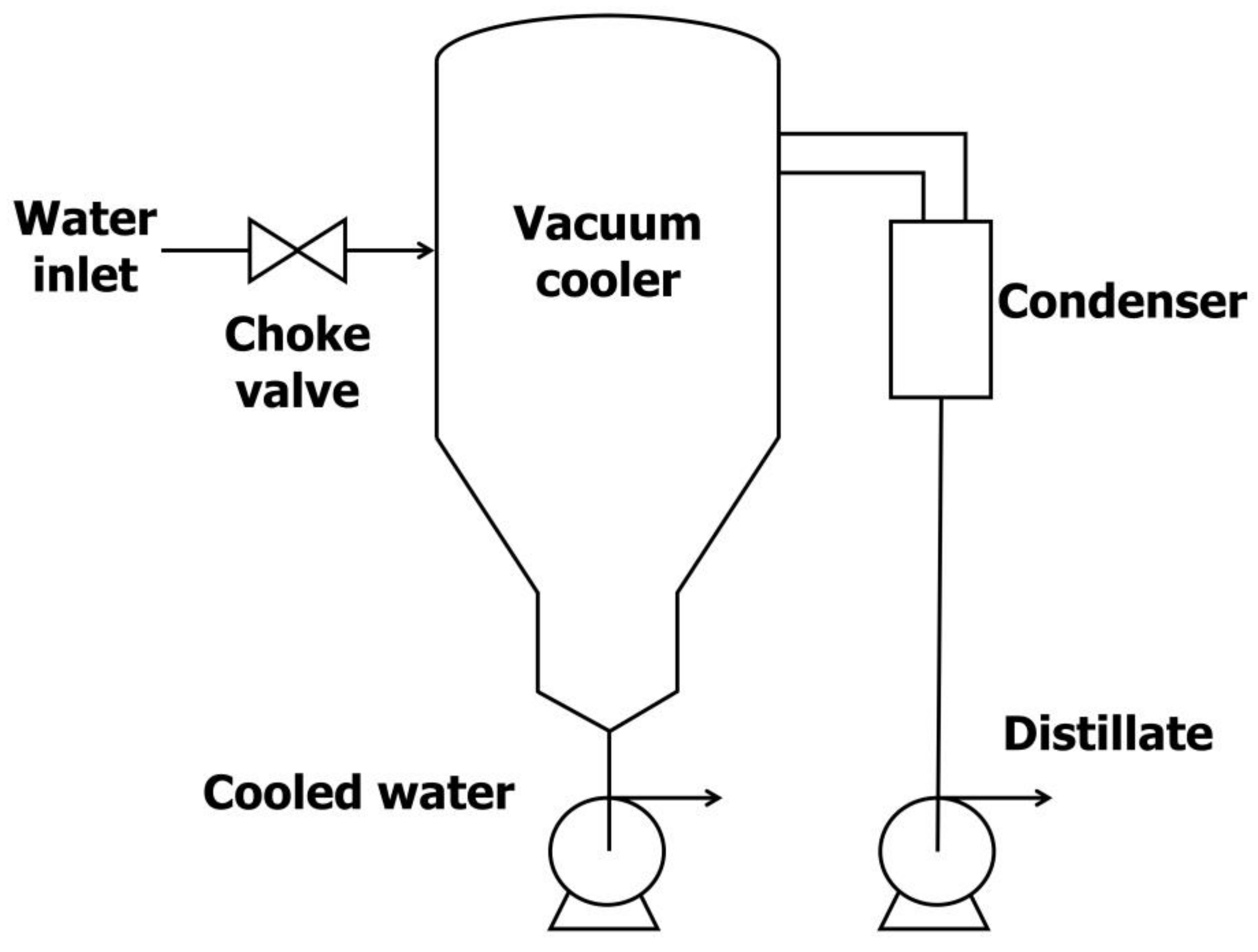
The vacuum cooling method is based on flash evaporation that uses the change in the equilibrium temperature of the fluids as a function of pressure. Decreasing the pressure decreases the equilibrium temperature; thus, as the superheated liquid enters the system with low pressure, flash evaporation occurs [
24]. The heat of evaporation (removed from the liquid by evaporation of part of the liquid) causes the temperature of the liquid to fall to the equilibrium temperature. The equipment for this type of cooling can be called a vacuum cooler or expansion cooler, because the expansion of the vapor occurs in this apparatus. A simple diagram of the vacuum cooler is shown in
Figure 2.
In the literature, application of this method for hot spring water cooling is not mentioned. However, this technology has been established in similar industries where the thermophysical properties of the fluids and surface fouling do not allow the application of conventional heat exchangers. Biziak et al. [
32] analyzed energy consumption for the continuous thermal processing of milk. The cooling of milk was carried out in the vacuum chamber, and the flash vapors were condensed in the cooling tower. The heat from the condenser was wasted, so the authors suggested the utilization of this waste heat. Zheng and Sun [
33] generally discussed vacuum cooling in the food industry. They mentioned that vacuum cooling can be used for many viscous food products (sauces, soups, fruit concentrates), which are difficult to cool because of the high heat transfer resistance caused by high viscosity and low thermal conductivity. The main advantages of this technology are a high cooling rate, low operating cost, and independence from the thermophysical properties of the cooled medium (viscosity and thermal conductivity). Major limitations include the loss of water from the processed product or the higher capital cost. According to Zhu et al. [
34], vacuum cooling (both spray and film) consumes significantly less energy than air blast cooling. However, they reported a reduction of volatile compounds in apple juice and milk during vacuum cooling.
The study by Khawaji et al. [
35] offers a review of seawater desalination technologies. One of the leading technologies in seawater desalination is multi-stage flash (MSF) distillation, which is based on the same principle as vacuum cooling (flash evaporation). The MSF process reduces the impact of scaling on heat transfer surfaces by eliminating boiling; however, some scale formation may occur. The high risk of scaling occurs in the heat exchanger, which heats the seawater before the vacuum chamber. Conveniently, this heat exchanger is not present in vacuum cooling operations. Due to the risk of corrosion, the material used for MSF plants is mostly stainless steel, to a lesser extent carbon steel, or more expensive materials. The work by Arnorsson [
36] does not deal directly with vacuum cooling but mentions findings related to geothermal water that affect this type of cooling. Boiling (especially its beginning) causes a significant drop in the partial pressure of CO
2 that leads to supersaturation of geothermal water with calcium carbonate, i.e., favorable conditions for sediment formation. Further boiling, if adiabatic, leads to cooling of the water, with the lower temperature leading to increased CaCO
3 solubility and less supersaturation.
The literature shows that vacuum cooling has been successfully applied in both the food industry, where the thermophysical properties of liquids and surface fouling limit the application of conventional heat exchangers, and in seawater desalination, where there is also a problem with scaling and corrosion. In the context of geothermal water, it can be problematic that CO
2 degassing and pH increase can be expected, which both modifies the composition of the water and creates more favorable conditions for scaling. Although Khawaji et al. [
35] reported that the elimination of boiling reduces the effect of scaling, it is necessary to take into account the different chemical compositions of seawater and geothermal water. Vacuum cooling can therefore be described as a promising technology. However, the suitability of its application needs to be validated experimentally due to the lack of successful references in the available literature.
3.3. Assessment of Cooling Technologies
In
Section 3.2, three methods for cooling geothermal water were introduced—indirect, direct, and vacuum cooling. All three methods are proven technologies for cooling highly mineralized waters. In this section, these methods will be assessed and compared.
The main advantage of indirect cooling is the simplicity of the process, which is formed by one relatively compact conventional heat exchanger. However, scaling usually occurs for mineral water applications. Therefore, several preventive measures are necessary to apply simultaneously, such as higher flow velocity, surface coating, corrosion-resistant materials, or possibility of disassembly. All these measures negatively influence operational and capital costs.
The benefits of direct cooling are the good accessibility of the cooling medium and elimination of the heat transfer surface, thus eliminating the scaling problem. The disadvantages are the specific climate in which the units are deployed (extremely low humidity) and the large built-up area. The relative humidity in the range of 15–20% in the studies presented in
Section 3.2.2. [
30,
31] is well below the average values in the Czech Republic, where humidity often reaches values just below the saturation limit, which suppresses evaporation and cooling. The average relative humidity in the Carlsbad region is between 74 and 90% [
37], and the average annual daytime temperature is 11.7 °C [
38].
Vacuum cooling is distinguished by its low operating costs and the relative independence of cooling performance from the fouling of the medium, as demonstrated by applications on a wide range of similar fluids. In terms of built-up area, it falls between direct and indirect cooling. In the context of hot spring water, a major drawback is the absence of specific applications in this area.
Table 2 was compiled on the basis of the literature review, the authors’ experience, and consultation with the industrial partner. This table represents the quality of the investigated technologies for selected parameters. Although this is a quantitative evaluation, it provides some guidance for selecting the appropriate technology. Vacuum cooling and indirect cooling were evaluated as suitable technologies for hot spring water applications. Both methods were subjected to experimental validation.
4. Case Study: Pilot Unit Design and Operation
The aim of this study was to experimentally verify the selected technology for cooling TMW in a specific balneological center. The experimental unit had to be designed and operated in such a way that it (a) respected the specifics and limitations of real operation, (b) was able to cool the required amount of TMW to the required temperature, and (c) provided insights for the techno–economic evaluation of full operation.
4.1. Facility Description
The following section assesses the current state of TMW usage by the balneological facility in areas relevant to the design and installation of the cooling technology. The information presented here has been provided by the operator.
The balneological facility is part of the spa hotel in Carlsbad. It provides over 25 thousand balneological treatments and consumes around 4300 m3 of TMW annually. The temperature of the TMW varies between 50 and 73 °C. Due to the high temperature, it is necessary to cool the TMW for treatments to about 37 °C, which is now solved by dilution with potable water, which is used for this purpose at about 3200 m3 per year. Due to the new legislative practice that prohibits the dilution of TMW, the operator is looking for new options for cooling TMW. In any case, it is necessary to take into account the increase in the abstraction and thus the costs of TMW. The current permit allows the operator to withdraw up to 10,500 m3/year (approx. 42 m3/day) at a price of EUR 4.19/m3.
TMW is distributed to customers in Carlsbad in allocated time windows. For this reason, TMW is accumulated in tanks with a total usable volume of 25 m3. With the increase in TMW consumption, it will be necessary to expand the accumulation capacity, which will significantly reduce the already limited space (approx. 12 m2) available to accommodate the technology.
Based on a chemical analysis of the TMW supplied to the spa hotel (
Table 3), the water has a slightly alkaline pH due to the presence of a specific ion. For the Carlsbad area, high concentrations of carbonates, sodium, and sulfates are specific. Compared with the characteristic chemical composition of these waters (
Table 1), there is a slightly lower concentration of calcium and iron ions. This could be due to formation of incrustation.
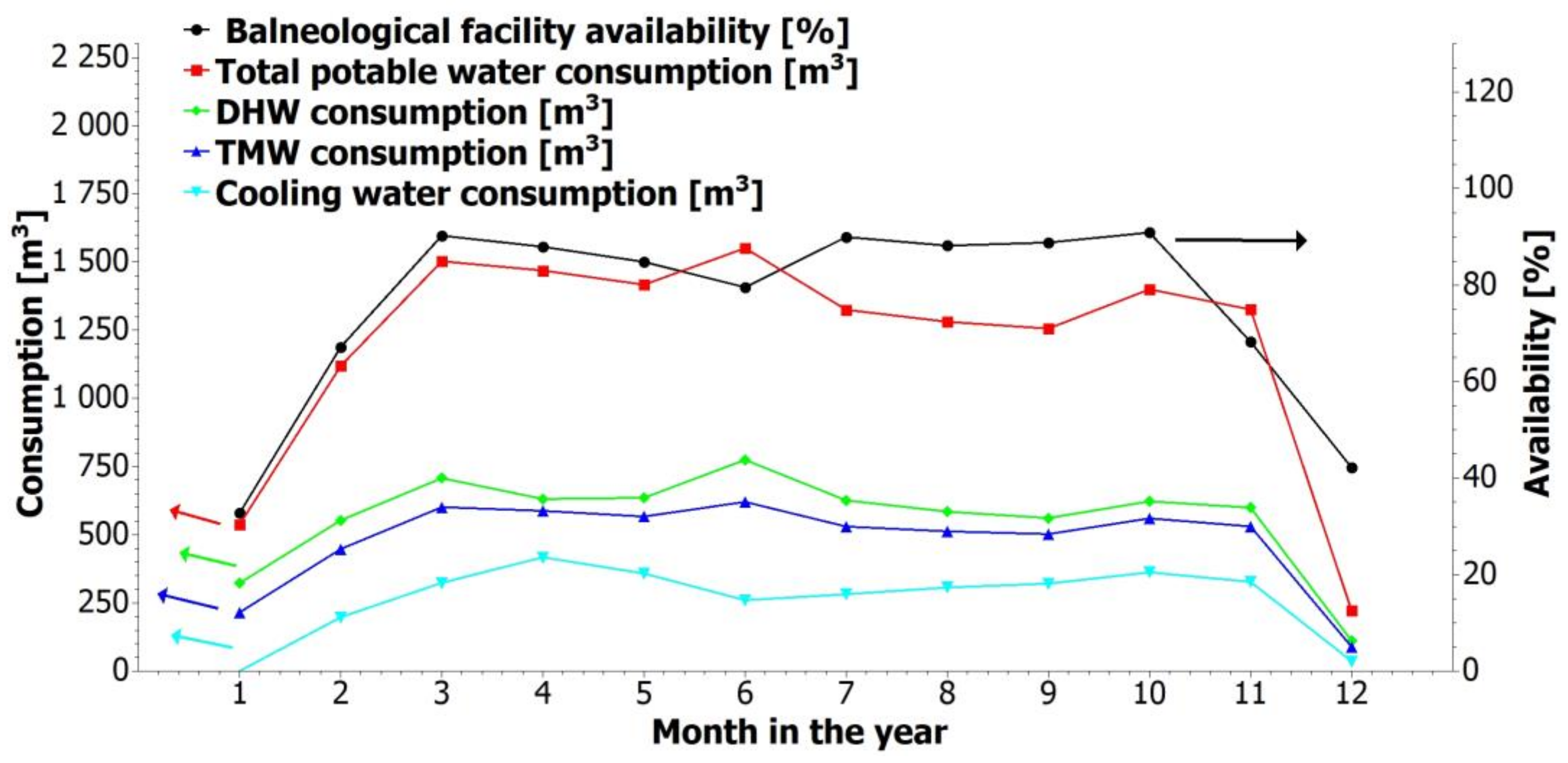
The cooling of the TMW will extract heat that has the potential for use in the direct hot water (DHW) system. The water for DHW is heated from 10 to 55 °C, and its consumption correlates with the hotel occupancy and therefore the consumption of the TMW. This fact favors the use of the available geothermal energy as it provides a relatively stable heat consumption without the need to build additional storage capacities. The use of geothermal heat from TMW cooling promises savings in thermal energy consumption. The current price of heat is EUR 19.25/GJ (excluding VAT), while a significant increase in this price can be expected in upcoming years. The potable and thermomineral water consumption during 2019 (the last full season without COVID-19) together with the occupancy of the spa hotel is illustrated in
Figure 3.
The operator has long-standing problems with the clogging of pipeline routes and storage tanks. The cooling technology must be as resistant as possible to mineral encrustation.
4.2. Pilot Unit Design
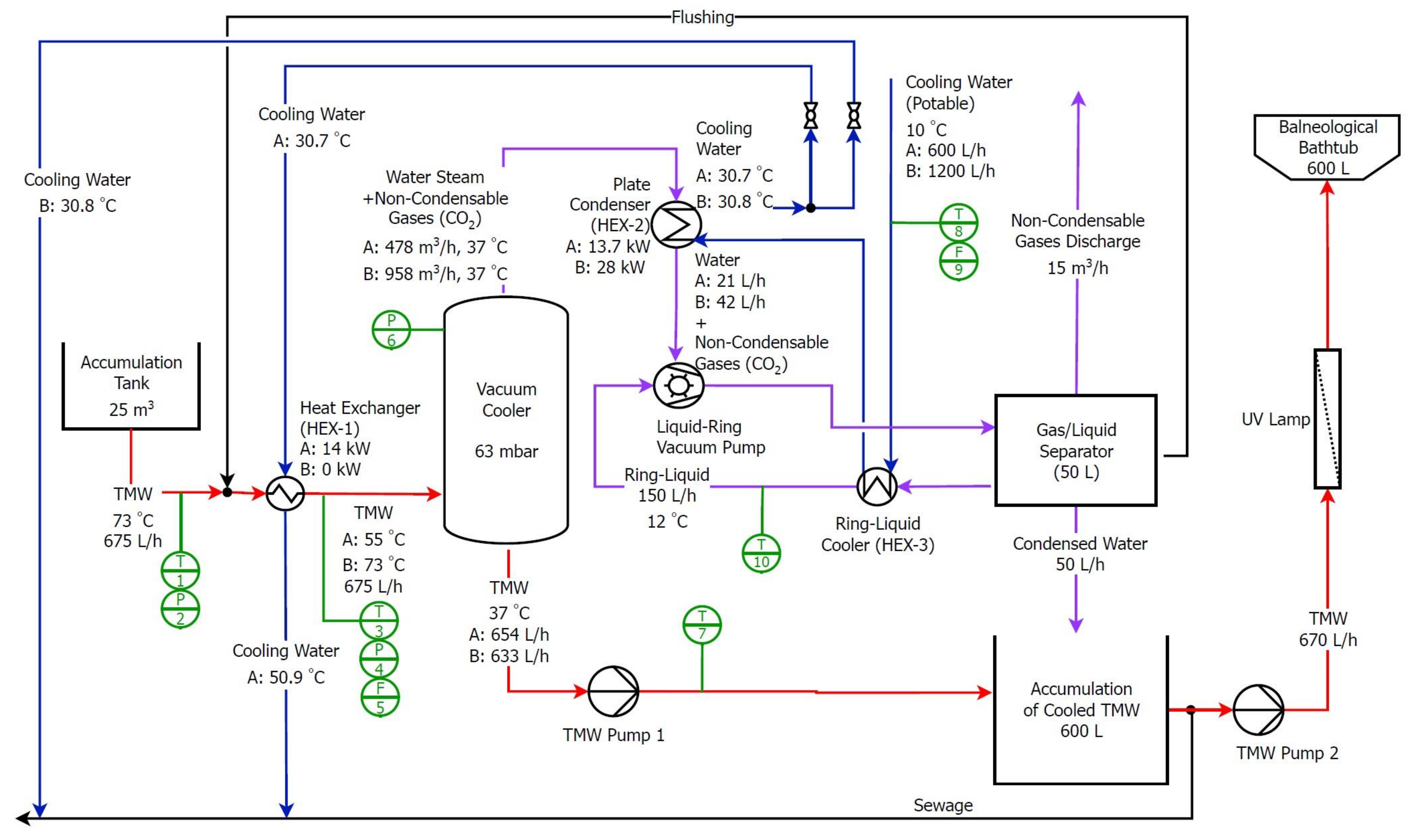
The pilot unit installed at the balneology facility consisted of two main components—a heat exchanger and a vacuum cooler—on which the designed cooling principles were tested and their operational reliability monitored. The process flow diagram of the technology can be seen in
Figure 4. It indicates the nominal design parameters of the unit based on energy and mass balance calculations. The design capacity of the unit corresponded approximately to the consumption of one balneological bath (675 L/h) with a maximum inflow TMW temperature of 73 °C.
Two modes of operation were investigated—simultaneous cooling by the plate heat exchanger (HEX-1) and the vacuum cooler (mode A) and cooling by the vacuum cooler only (mode B). TMW entered the process through the plate heat exchanger HEX-1 (SWEP E5THx10/1P) where it was partially cooled in case of mode A. Subsequently, the TMW was fed to the vacuum cooler where it was cooled to the desired temperature of approximately 37 °C by flash evaporation. The vacuum cooler was designed as a cylindrical pressure vessel (DN 250) and made of AISI316L stainless steel.
Through Pump 1 (Calpeda NGL 4/110), the cooled TMW was discharged into a 600L accumulation tank. At the operator’s command, the cooled water was pumped (Pump 2, EBARA DWO 150) into the balneological bath. A UV lamp (monolamp HA325 W-720) was installed behind Pump 2 to eliminate possible microbial contamination, the risk of which increases significantly with TMW at temperatures around 40 °C.
The water vapor released during expansion was condensed at the HEX-2 heat exchanger (Sondex S19A-IG10-7-TK) and extracted from the system along with non-condensable gases (mostly air + CO2) via a liquid-ring vacuum pump (WaterVac VBV2 070). Cold potable water from the water supply system was used as cooling water for the vacuum pump and heat exchangers.
The condensed water with a low level of mineralization was used to flush the system at the end of the operating cycle, minimizing the level of encrustation in the apparatuses and piping. Another measure to minimize fouling was to ensure sufficient TMW velocity (min. 1 m/s) in the pipeline.
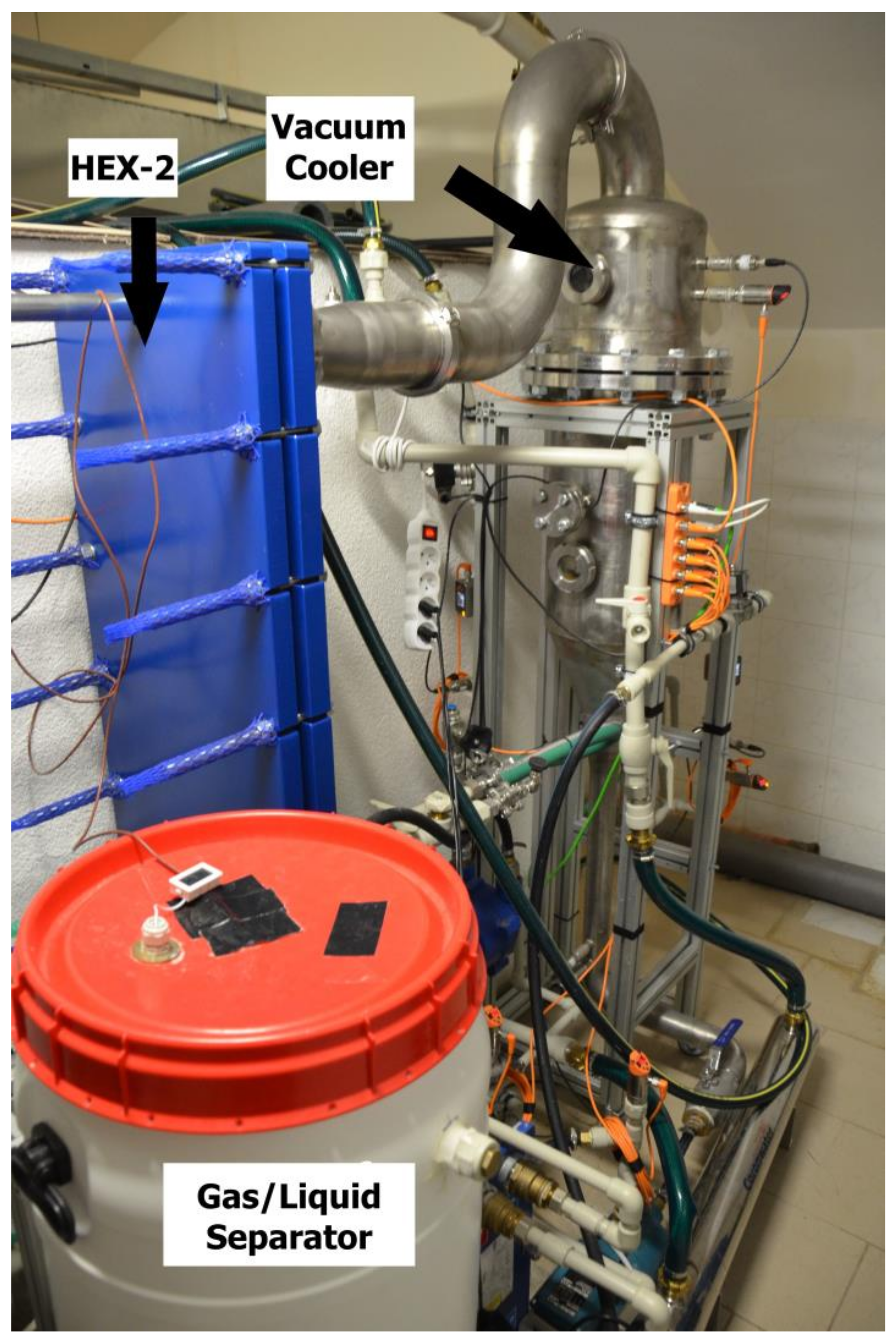
The pilot unit was equipped with IoT temperature (IFM TN2435) and pressure (IFM PN2594) sensors, flowmeters (IFM SM6020), and IO-link master AL1342. Operational data was stored in minute intervals in a cloud database. A photograph of the pilot cooling unit is shown in
Figure 5.
4.3. Pilot Unit Operation
The pilot cooling unit was operated between May and December 2022, and was part of the live operation from July 2022. The unit was manually controlled by the technical staff of the balneology center. The TMW flow rate was adjusted with respect to the current inlet temperature and the required TMW outlet temperature of around 37 °C. With respect to the required cooling capacity, the unit was operated in either mode A or B, with mode A providing greater cooling capacity. During the period under review, the plant completed a total of 97 duty cycles. Each cycle (working day) was of varying length depending on the actual load on the balneological bath. The operator’s task was to flush the system with condensed water at the end of each working cycle to minimize the risk of fouling.
5. Results
This chapter presents the obtained operating data and experience, and technically and economically evaluates the potential use of the cooling technology in the full operation of the balneological facility.
5.1. Operating Parameters
The cooling pilot unit has been tested in live operation for six months. The results of this test are presented in
Table 4, which shows the standard deviation, average, minimum, and maximum values for the individual measured parameters. The average TMW temperature at the heat exchanger inlet was 55.5 °C. The results confirm that this cooling unit is capable of cooling TMW to the required 37 °C, with an average TMW temperature after the vacuum cooler of 37.9 °C. The average TMW flow rate was 0.5 m
3/h, and a total of approximately 182 m
3 of TMW flowed through the cooling unit during the experiment. The average heat output of the heat exchanger was 3.2 kW. The average pressure in the vacuum cooler, which determines the TMW outlet temperature, was −0.90 barg, and the minimum pressure reached in the vacuum cooler was −0.95 barg.
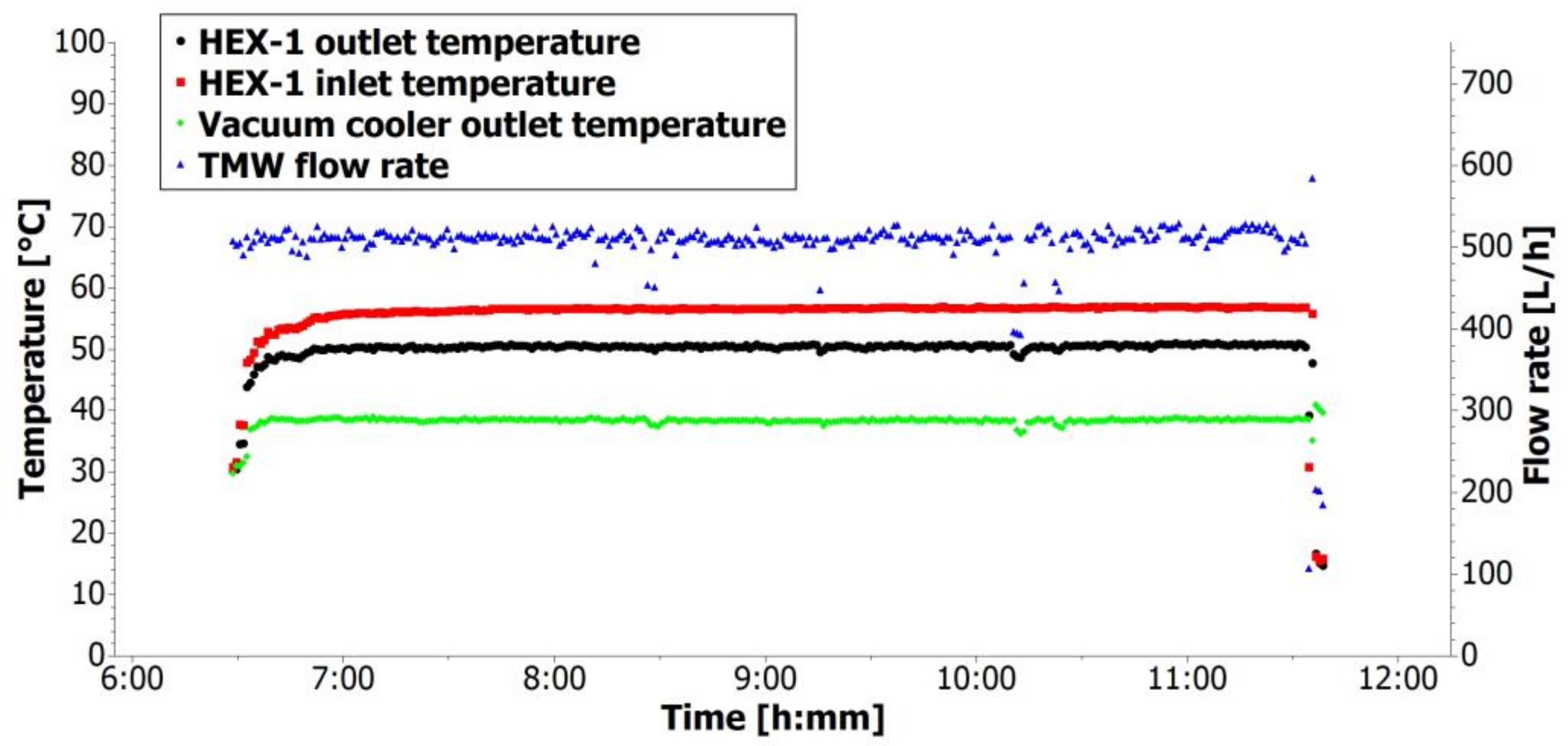
The progression of TMW temperatures and TMW flow rate for one day in mode A are captured in
Figure 6. It can be seen that the inlet thermal mineral water temperature was about 56 °C. The heat exchanger cooled the TMW to approximately 50 °C, and after the vacuum cooler, the TMW temperature was about 38 °C. This outlet temperature of thermal mineral water was slightly higher than required, but this difference is acceptable. The TMW flow rate was about 0.5 m
3/h.
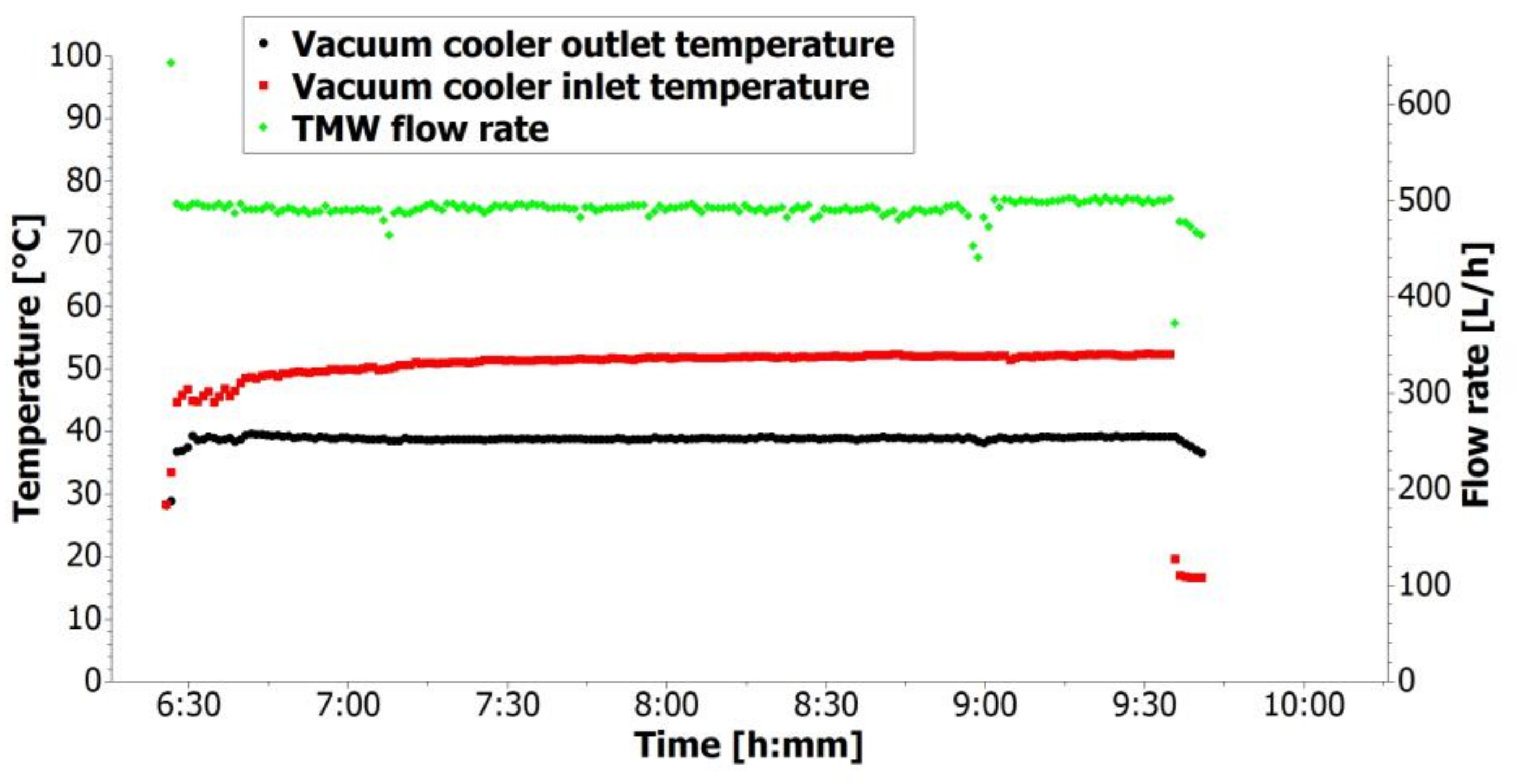
Figure 7 shows the history of TMW temperatures and TMW flow rate for one day in mode B. The TMW inlet temperature was about 50 °C for this day. The vacuum cooler alone was capable of cooling down the temperature to 38.8 °C at an average flow rate of 0.49 m
3/h. In both
Figure 6 and
Figure 7, the start-up and shutdown period of the cooling unit can be observed. The start-up periods were approximately 10 min long, while the shutdowns were very quick. In addition, the average, maximum, and minimum TMW temperatures and TMW flow rates for both modes are presented in
Table 5.
The operation of the pilot unit was mainly (64% of the working time) in mode A, i.e., with simultaneous cooling of the HEX-1 and the vacuum cooler. This was mainly due to the lower than expected cooling capacity of the vacuum cooler, which at TMW flow rates of around 0.5 m3/h was no longer sufficient, and the TMW output temperature was increasing. Therefore, to maintain the required TMW temperature at the required flow rates, it was necessary to use the HEX-1 cooling and thus increase the cooling capacity. The average cooling capacity was 3.2 kW for the HEX-1 and 7.2 kW for the vacuum cooler.
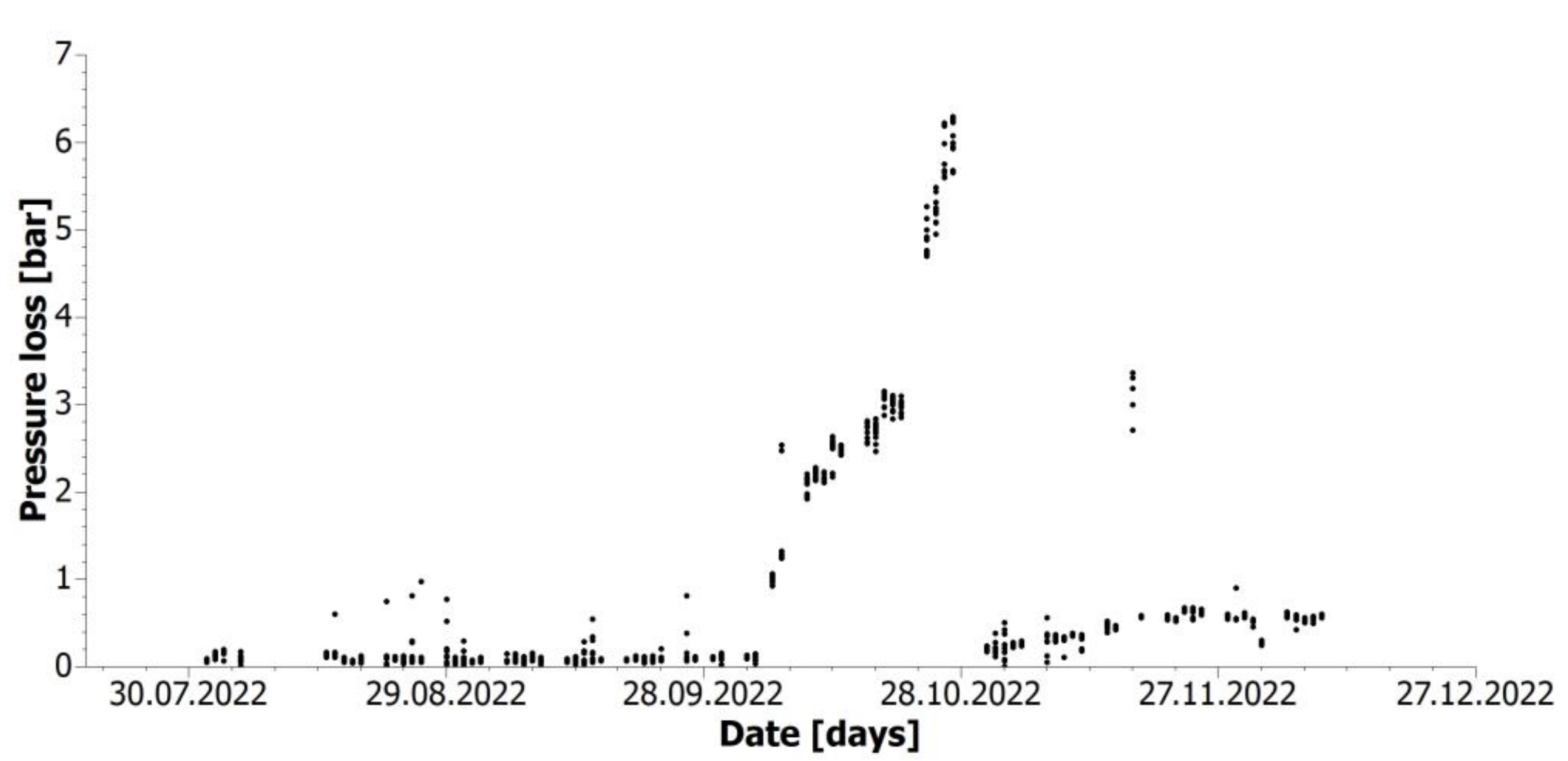
Figure 8 shows the pressure loss on HEX-1 during the experiment. The pressure loss is almost constant during the first half of the experiment. However, at the beginning of October, maintenance work was carried out on the pipeline upstream of the cooling unit. After this maintenance, a sudden temporary rise in pressure loss occurred due to clogging of the heat exchanger inlet. After cleaning the HEX-1 inlet, the pressure loss decreased again, although to a higher level than before the maintenance. During the last two months of the experiment, the pressure loss gradually increased. Descriptive statistics were used to compare HEX-1 performance in the first and second half of the testing period. A few days from each half with comparable values (temperatures, flow rates) were identified. The results are summarized in
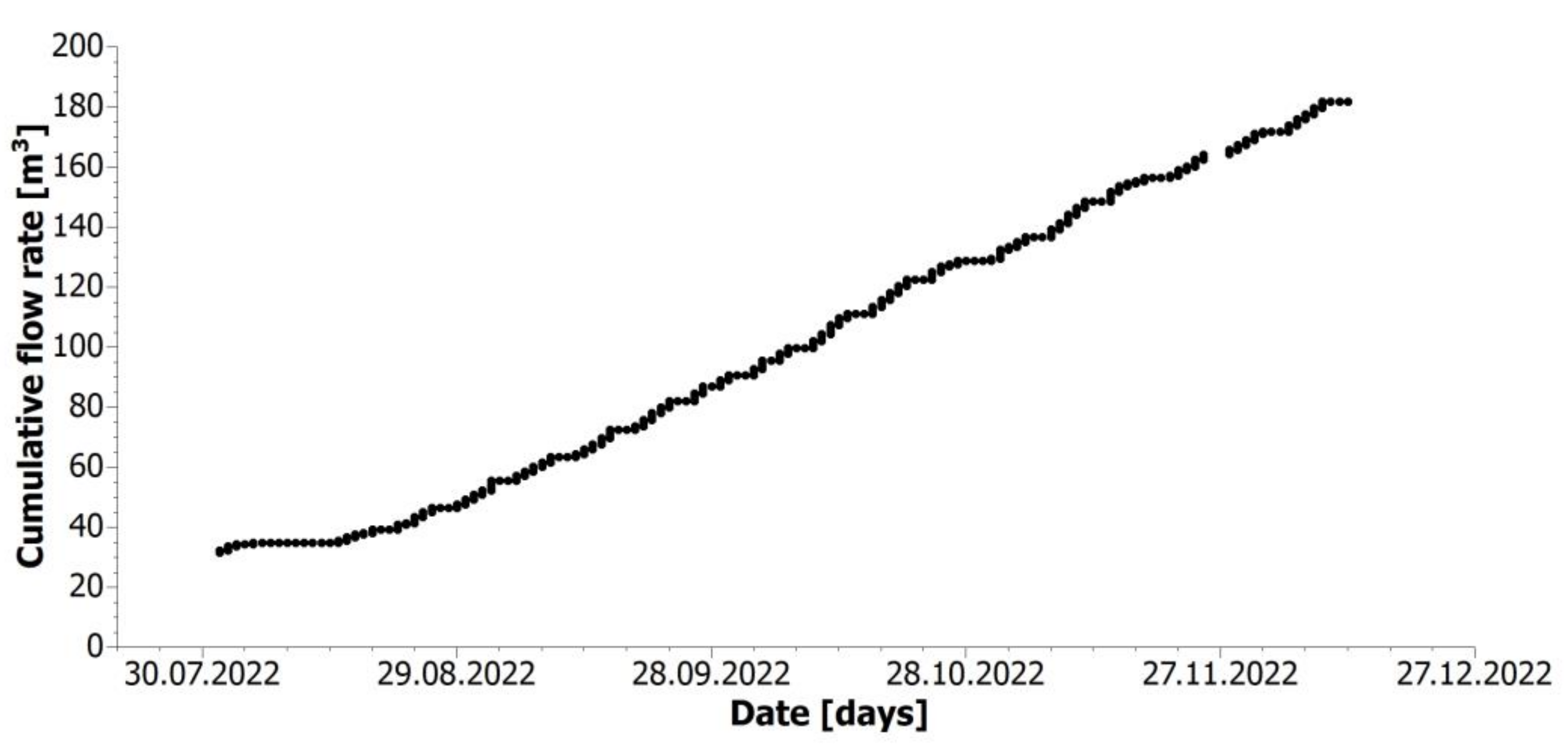
Table 6. Clearly, the performance decreased over time. In
Figure 9, the cumulative TMW flow rate is shown. It can be seen that the cumulative flow rate evenly increase from the end of August to December.
After the experiment the HEX-1 was cut.
Figure 10 shows that the TMW inlet throat is heavily fouled while the plates of the heat exchanger are only slightly fouled.
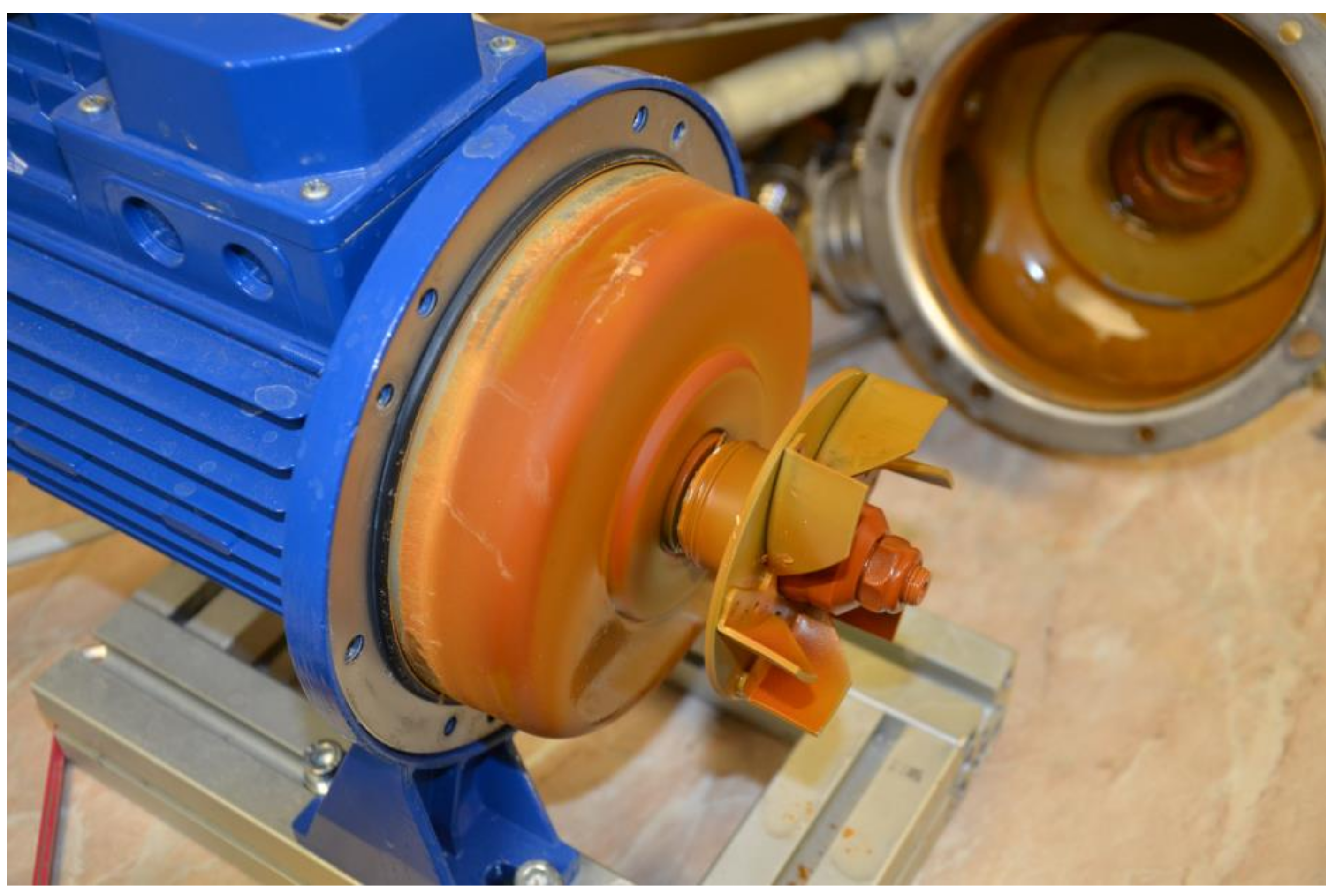
The cooling system should be flushed with condensed water by the operator regularly, always at the end of the working cycle. This procedure was only followed 87% of the time due to human factors. In 13% of the cases, the pipes and apparatus were exposed to more than 12 h of TMW. Even so, the flushing resulted in a significant reduction in fouling. In
Figure 11,
Figure 12,
Figure 13 and
Figure 14, the difference between the flushed components and those parts of the technology that were not flushed (PUMP 2, UV lamp) is clear. The non-rinsed components were covered with a rusty encrustation that was removed using 10% wt. sulfamic acid.
5.2. Techno–Economic Assessment
In this section, a techno–economic assessment for the cooling unit in a particular balneological facility is provided. Operating and investment costs as well as financial savings and returns are estimated and calculated. The costs quoted are for a full-scale cooling technology in an arrangement corresponding to the pilot unit, that is, a combination of a plate heat exchanger and vacuum cooler, which together combine the advantages of robust operation and easy control of outlet temperatures. In this arrangement, the plate heat exchanger would be used mainly for peak shielding and the stabilization of the process, and its exposition to the TMW would be minimized.
Operational costs consist of the cooling technology operating costs (maintenance of equipment, electrical consumption of pumps and vacuum pump, consumption of water), operating costs of UV lamps, and costs for increased hot spring water consumption. Investment costs include costs for individual apparatuses and accessories (heat exchangers, expansion cooler, pumps, pipes, fittings, etc.), wirings, a system for measurement and control, an accumulation tank or assembly, and the commissioning of technology. Financial revenue is made up of savings on domestic hot water heating and savings on consumption of potable water, which was used for cooling so far. Additionally, the securing of income from the provision of balneological treatments can be considered into financial revenues. This income is strongly dependent on the introduction of cooling technology which does not change the chemical composition of hot spring water. Balneological treatments could not be provided without such technology.
In
Table 7, the total annual operating costs and the investment costs are quantified for two options. Option 1 is for the maximum possible daily consumption of hot spring water (42 m
3), and option 2 is for the average daily consumption of hot spring water (30 m
3). Electrical energy costs, maintenance costs, costs for additional hot spring water abstraction, savings for DHW, and savings for cooling water costs are considered for the calculation of total operating costs. Investment costs are estimated on the basis of consultations with the industrial partner.
From
Table 7, it is evident that the cost of additional hot spring water abstraction is the highest operating cost. However, these costs are determined by legislative requirements and would be the same for all technologies. Electrical energy and maintenance costs are significantly lower than the costs for hot spring water abstraction. Total operating costs are fully (option 1) or mostly (option 2) compensated by savings for DHW and potable water. This means that the operation of the cooling technology will not be a burden on the hotel’s budget.
The investment cost of the proposed cooling technology is EUR 235,000. Based on this assessment, these costs do not appear to be recovered. However, it should be noted that the implementation of cooling technology will allow the company to continue providing balneological treatments, which are an important part of the facility’s income. Therefore, it can be assumed that this income will ensure the return of investment costs. Unfortunately, no data were provided on the income from balneological treatments at the balneological center. Therefore, this income could not be included in the techno–economic assessment.
6. Discussion
6.1. Evaluation of Cooling Technologies
Both technologies tested have demonstrated the ability to cool TMW from the Carlsbad Spring in long-term operation. Both technologies can also be used for DHW heating and therefore for geothermal energy recovery. Nevertheless, each technology has different operational advantages and disadvantages, which will be discussed further below.
The plate heat exchanger has confirmed its status as an efficient and cheap technology, which is, however, sensitive to fouling (see
Section 6.2 for details). Fouling problems from coarse sediment could be partially reduced by placing a filter in front of the exchanger to eliminate the introduction of incrustations released from the storage tanks and piping upstream of the cooler. However, due to the intense formation of incrustations, it would be necessary to consider its regular cleaning or replacement. With regard to the deposition of calcium compounds on the heat exchange surfaces, the assumption of a positive influence of the TMW flow velocity (or the high shear stress respectively) in the boundary layer of the plate heat exchanger was confirmed. The design shear stress of the HEX-1 plate heat exchanger was 61 Pa. For larger (full-scale) exchanger sizes, the risk of plate vibration will have to be taken into account. This risk can be partially reduced by connecting smaller exchangers in parallel, but this will lead to an increase in investment and operating costs.
Unlike the heat exchanger, the vacuum cooler has demonstrated greater operational robustness and resistance to encrustation. However, it is a more technically complex and investment-intensive solution. The experiment showed the requirement to reduce the pressure loss between the vacuum pump and the cooling chamber—at higher flow rates (approx. above 0.5 m3/h), the piping route was overwhelmed by steam, and the pressure in the expansion chamber increased above the value of −0.9 barg, resulting in insufficient cooling of the TMW. In the case of full operation, it would be necessary to size the piping to larger diameters and consider using a different type of condenser (e.g., tubular) that would generate less pressure loss. Another measure may be to use a vacuum pump with a larger suction capacity or lower operating pressure. In terms of future design activity, it will also be necessary to investigate in detail the volume of released non-condensable gases (especially CO2) that need to be removed from the system.
6.2. Fouling
The conducted experiment confirmed that fouling is the main operational problem in TMW cooling. Based on operational data and experience and visual inspection of the piping and equipment after the pilot tests, two predominant types of fouling are (a) fouling (clogging) due to lose incrustations and (b) the formation of a continuous layer of calcium deposits on the surfaces.
The effect of the first type of fouling was particularly evident in the operation of the plate heat exchanger (HEX-1) and resulted in a sharp increase in pressure drop during October 2022. As a result of the service intervention, the piping upstream of the cooling technology was drained and dried out. After the restart, it is likely that the inlay layer was torn off and entrained into the exchanger. The inlet could not be cleaned completely. As a result, the pressure drop across the exchanger grew faster in the last phase of the experiment (from the end of October) than in the first half of the live operation (see
Figure 8).
From
Figure 10, which shows the condition of the exchanger HEX-1 at the end of the pilot run, it is clear that only the inlet to the TMW was clogged. The heat exchanger itself showed minimal fouling with calcium compounds, which had a negligible effect on the operation of the exchanger. Similarly, the formation of a continuous layer of calcium deposits was minimized on all operating surfaces that were (a) regularly flushed with condensed (demineralized) water, thereby reducing the exposure time to TMW, and (b) where sufficient TMW flow rates were maintained. This observation is consistent with other studies [
19,
20,
21,
22]. The surface roughness also had a positive effect. The polypropylene pipe with the lowest roughness showed the least evidence of fouling.
6.3. Geothermal Heat Recovery
The use of geothermal heat is facilitated by the favorable correlation between hotel occupancy, TMW consumption, and DHW consumption, which allows for continuous heat extraction. The potential revenue from the geothermal energy recovery is one of the main operational benefits of the installation of the cooler. The thermal energy savings can range between 500 and 780 GJ per year. The geothermal energy yield could be further increased by installing additional DHW storage capacity. Theis would ensure the use of thermal energy during periods of peak TMW demand and low DHW consumption.
In terms of geothermal energy use, the design of a full-scale unit will be more complex for a vacuum cooler. In order to ensure a sufficient temperature level (min. 50 °C) for DHW, it will be necessary to design the cooler as a multi-stage unit with gradually decreasing pressure and therefore decreasing equilibrium temperature of the released vapors. This measure will ensure the necessary temperature gradients on the condensing exchangers in which the DHW will be heated. A minimum five-stage unit is suggested for full-scale operation.
6.4. Techno-–Economic Perspective
As shown in
Table 7, the positive conclusion of the techno–economic assessment for the operator is that the cost of operating the technology will be essentially offset by savings in heat to the DHW system and potable water consumption.
Operational savings from the operation of the cooling technology are likely to increase in the future. The expected increase in thermal energy prices to around EUR 42/GJ and the rising cost of drinking water (expected to increase by around 30%) will have a positive effect. On the other hand, electricity costs are expected to rise to around EUR 34/MWh. However, electricity consumption has little impact on the overall financial balance. With the above price increases, the total annual operating cost balance could be between EUR 13,600 and EUR 22,000 for option 2 and option 1, respectively.
7. Conclusions
The present study experimentally investigated two technologies for the cooling of TMW in a real balneological operation in Carlsbad, Czech Republic. During a six-month trial run, both technologies (indirect and vacuum cooling) demonstrated the ability to effectively cool thermomineral waters.
Indirect cooling using a plate heat exchanger is a cheaper option but with a higher susceptibility to fouling. For full-scale use, it is recommended to design the plate heat exchanger with a high wall shear stress value and to provide filtration of coarse contaminants at the heat exchanger inlet. Over time, a decrease in heat exchanger performance was observed. Quantification of the effect of flow rate, temperature, TMW pH, and pressure drop on the heat exchanger fouling rate should be the subject of further study.
Cooling using vacuum expansion proved to be an effective and robust solution. The disadvantage is the higher investment costs compared to indirect cooling. In full operation, it is recommended to reduce the pressure drop across the condensate exchanger. To this end, further research should be directed towards an accurate determination of the volume of carbon dioxide released during the vacuum cooling of TMW.
The fouling of the technology, which is a major problem in TMW cooling, can be effectively reduced by regular flushing of the pipes and apparatus. A major financial benefit for the operator of the balneothermal facility is the possibility of using geothermal heat for DHW heating. This opportunity applies generally to many spa facilities in Carlsbad.

 ,
, 


