1. Introduction
Growing concerns about greenhouse gas emissions are raising awareness about their impact on human life. Climate change is becoming increasingly palpable, with unexpected floods and high-temperature records being reported repeatedly across the globe, possibly due to escalated greenhouse gas emissions [
1]. Moreover, improving energy efficiency across all sectors has become a necessity, given the limitations of relying solely on fossil fuel energy and the increasing demand for benign energy in society.
In the UK, the domestic building sector is the second-largest energy consumer sector [
2], accounting for 28% of total energy consumption. If industrial buildings are included, the energy consumption of the building sector would exceed 30% [
2]. Furthermore, the building sector is responsible for around 34% of the country’s total CO
emissions [
3].
Embracing renewable energy technologies in buildings is among the most effective means of reducing energy consumption, promoting sustainable development, and transitioning to clean energy [
4]. Consequently, there has been a growing interest in improving the energy performance of building facades by adopting multi-functional and energy-efficient facades.
Building Integrated Photovoltaics (BIPV) was introduced as an alternative to conventional building envelopes, such as walls, roofs, and even windows, by serving as a semi-transparent facade [
5]. Semi-Transparent Photovoltaic (STPV) glazing evolves the facade by regulating room illuminance, preventing excessive glare, and limiting heat gain [
5]. Simultaneously, the Photovoltaic (PV) solar cells integrated into the facade function as environmentally friendly electricity generators. The glazing has been widely researched and analyzed in the literature, as discussed in the following section.
Solar cells are devices that convert sunlight into DC electricity through the photovoltaic phenomenon and can be classified into the first, second, and third generations [
6]. The adoption of all generations of solar cells has been investigated in BIPV and STPV facades [
7].
Crystalline Silicon (c-Si) solar cells, also known as first-generation cells, are a mature technology and are still of interest for their durability and consistent performance [
5,
8]. Despite c-Si being opaque, a spaced-type glazing structure has been developed to incorporate the cells [
9].
The high cost of c-Si solar cells has led to the development of second-generation cells that are semi-transparent and allow natural daylight to pass through, providing indoor lighting [
6]. This feature makes second-generation cells suitable for STPV glazing [
5]. However, the efficiency of the second generation is not as desirable as that of the first generation [
6].
Although stability issues currently limit the use of third-generation solar cells [
5], their unique properties make them a promising option for future use in BIPVs. Researchers are exploring utilizing third-generation cells such as Dye-Sensitized, Organic, and Perovskite cells [
6] in BIPV due to their low cost, sensitivity to light, simple fabrication process, and potential for large-scale applications [
7,
8].
Photovoltaic glazing devices can restrict heat gain by decreasing light transmittance [
9]. However, they may lead to an increase in the building cooling load due to the waste heat generated in the cells [
10]. To address this issue, photovoltaic glazing can be combined with vacuum glazing, which is an excellent thermal insulating facade element [
11]. Zhang et al. [
10] introduced a four-layer glass pane combination of photovoltaic glazing and vacuum glazing to achieve a low U-value glazing system while generating electricity through the glazing surface.
The combination of photovoltaic and vacuum glazing has been the focus of several research groups. The Hong Kong Polytechnic University, for instance, developed a Vacuum Photovoltaic Insulated Glass Unit (VPV IGU) with semi-transparent amorphous Silicon (a-Si) PV cells [
12,
13]. The University of Nottingham proposed a four-layer photovoltaic vacuum glazing system (PV-VG 4L) [
14] and later investigated a lighter and thinner concept (PV-VG 2L) with the PV cells inside the vacuum gap [
15]. Furthermore, a three-glass layer system with spaced c-Si opaque PV cells [
16] and a three-layer system with Cadmium Telluride (CaTe) semi-transparent PV cells [
17] combined with vacuum glazing have also been investigated.
The use of concentrators has been extensively explored in the literature. For instance, [
18] presents an experimental and simulative study on a novel concentrator-photovoltaic window (CPVW) that provides uniform daylighting. The study in [
19] proposes a new type of window, known as an asymmetric concentrator-PV window, which can achieve an optical efficiency above 80% over a broad acceptance range of 10
–85
. In addition, [
20] report a novel kind of photovoltaic glazing called 3D concentrating photovoltaic, which has been shown to increase the maximum power output by 2.89 times in tests. Another example is the Building Integrated Concentrating Photovoltaic (BICPV) smart window described in [
21]. The study finds that BICPV has the potential to increase the maximum power output by 17.1%.
Furthermore, a semi-transparent multifunction glazing concept has been introduced [
22] and investigated in various studies. The Centre for Sustainable Technologies at the University of Ulster developed the glazing prototype that features an outer glass panel shaped into multiple lenses to concentrate solar radiation onto photovoltaic cells [
23]. The basic version of the concept is known as Concentrating Photovoltaic Glazing (CoPVG), which can be enhanced by adding a glass pane to the outer surface to improve its U-value and thermal energy harvesting potential. The gap between the outer glass and the lens can be either filled by air or evacuated. When the gap is evacuated, the device is called Concentrating Photovoltaic Evacuated Glazing (CoPEG) [
23].
Another version of the glazing includes an inner glass pane that creates a cavity at the backside of the lenses. Forced air flows through the cavity to decrease the temperature of the photovoltaic cells, so as to increase their efficiency while generating hot air for heating purposes, for example. This version is titled Concentrating Photovoltaic/Thermal Glazing (CoPVTG) [
24]. Additionally, the authors are developing a new approach using individual and separated lenses. Although there are differences between the versions, the optical behavior of the glazing depends on the geometry of the lenses, the optical properties of the materials, and the quality of the surface, which remains consistent among all the aforementioned versions.
The objective of this paper is to experimentally characterize the optical performance of CoPVG. The research was conducted by performing an outdoor test on the individual prisms. The optical efficiency, which is the fraction of irradiation power on the glazing surface captured at the focus of the lens, which varies for different light directions, was measured and compared with an analytical model. An optical map was then generated using the model to depict the relationship between incident direction and optical efficiency, providing useful information on the seasonal effects of the glazing. The optical map demonstrates how the glazing permits more light to enter the building during winter and blocks the window during summer. Furthermore, a study was conducted to compare the CoPVG with traditional spaced-type STPV glazing with the same opaque area percentage to demonstrate the advantages of the concept.
2. Definitions
The optical efficiency of concentrators, defined as the fraction of radiation power on the aperture that reaches the focus, can exhibit directional dependence. This phenomenon is observed in CoPVG lenses.
The optical efficiency of CoPVG lenses is dictated by their geometry rather than the efficiency of the photovoltaic cells. Therefore, the shape of the lens can be customized to account for the location of the building. Additionally, the efficiency is influenced by the surface quality and the optical characteristics of the material, such as the refractive index, absorption, and scattering coefficient. For the lenses, a polished surface that is predominantly spectral is desirable.
The aperture surface is conventionally regarded as the reference plane for studying concentrators, irrespective of their mounting location [
23,
25,
26], whether on building facades or the ground. In this investigation, the reference plane was modified to the horizontal plane on the earth, which is more applicable for assessing the efficacy of multifunctional glazing systems in buildings. This reference plane is compatible with commercial energy modelling software like Integrated Environmental Solutions (IES) packages. Utilizing this coordination system, known as
solar coordination, provides greater flexibility in analyzing the performance of glazing by considering three independent variables: the building’s location, the glazing’s orientation, and the ambient solar obstacles.
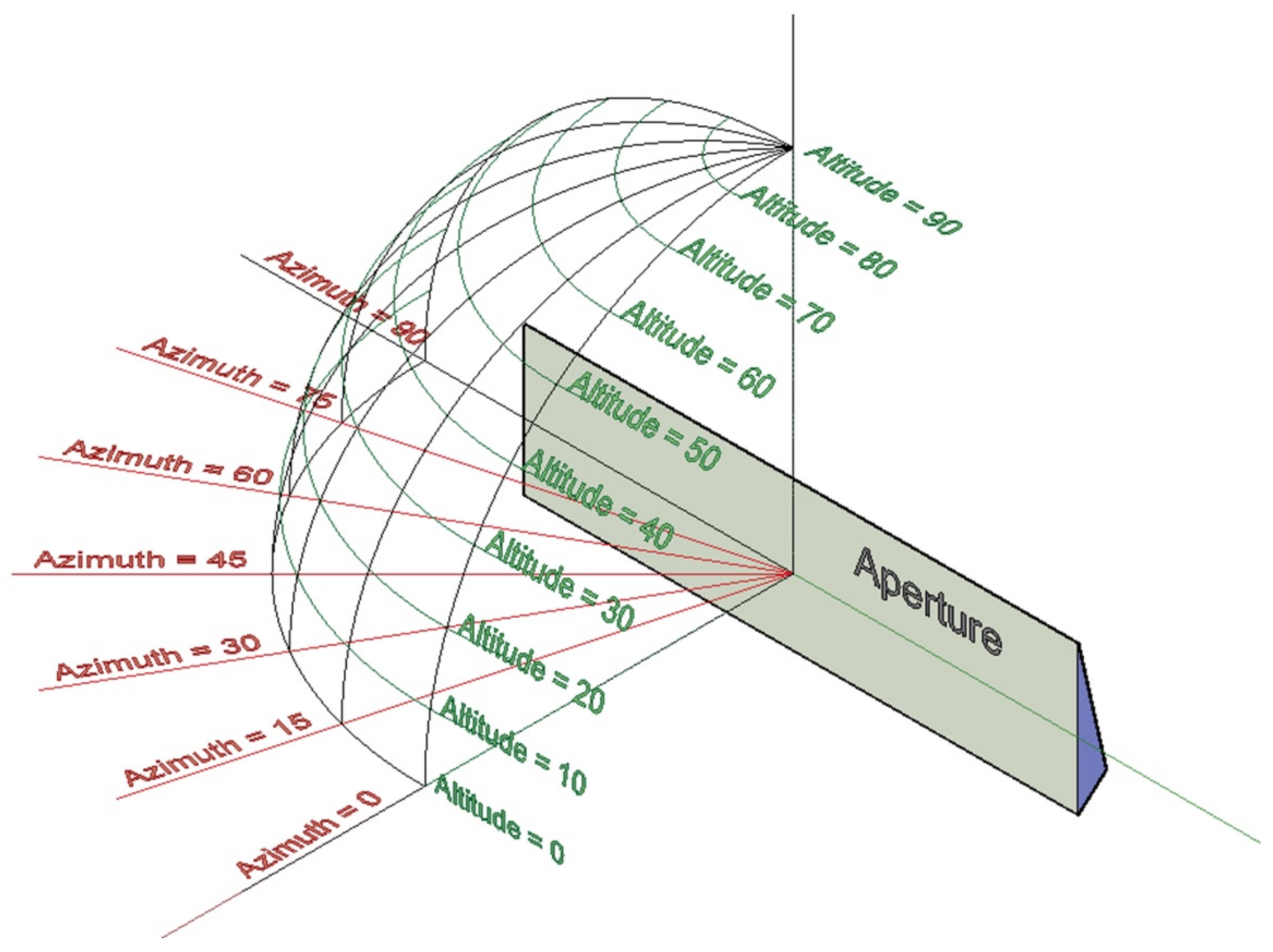
Within the solar coordination system, the altitude angle is defined as the angle between the incident beam (i.e., the sun) and the projection of the beam onto the horizontal surface. The azimuth angle is defined as the angle between the projection of the light beam on the ground and the north.
In the case of CoPVG lenses, it is essential to note that, as the altitude angle increases, it eventually reaches a specific angle known as the
switching angle. At this angle, the incident radiation beam is no longer transmitted through the prism but reflected into the lens area due to
Total Internal Reflection (TIR), which occurs at any altitude angle above the switching angle. Moreover, the switching angle varies depending on the azimuth angle.
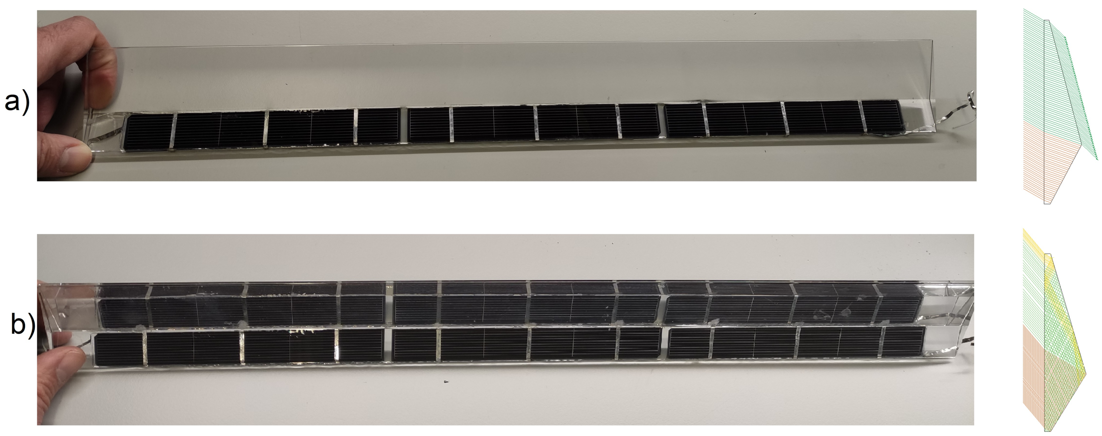
Figure 1 illustrates the response of the CoPVG lens at various altitude angles. The figure demonstrates that when the beam strikes the aperture at an angle below the switching angle, as shown in
Figure 1a, a portion of rays will pass through the lens, enabling daylighting. This situation is relevant to winter conditions when the sun is at a low altitude. Conversely, during summer when the sun is at a higher altitude, the irradiation beam strikes the aperture at angles above the switching angle, as shown in
Figure 1b. In this scenario, no rays will transmit, but will theoretically concentrate on the focus. The distinct behavior of CoPVG lenses throughout the year is referred to as the
seasonal effect.
3. Experimentation Methods
An outdoor experiment was conducted to evaluate the optical performance of individual CoPVG lenses fabricated from clear glass with the same physical characteristics as the Pilkington Optiwhite glass. The objective was to determine the optical efficiency in diverse directions and compare the actual performance of the lens with analytical solutions.
To evaluate the optical performance of the lens, the efficiency variation was measured at several altitude angles for a range of azimuth angles, including 0
, 15
, 30
, 45
, 60
, and 75
.
Figure 2 depicts the direction of the incident light used in the experiment striking the aperture surface of the lens within a quarter of the coordination above the ground.
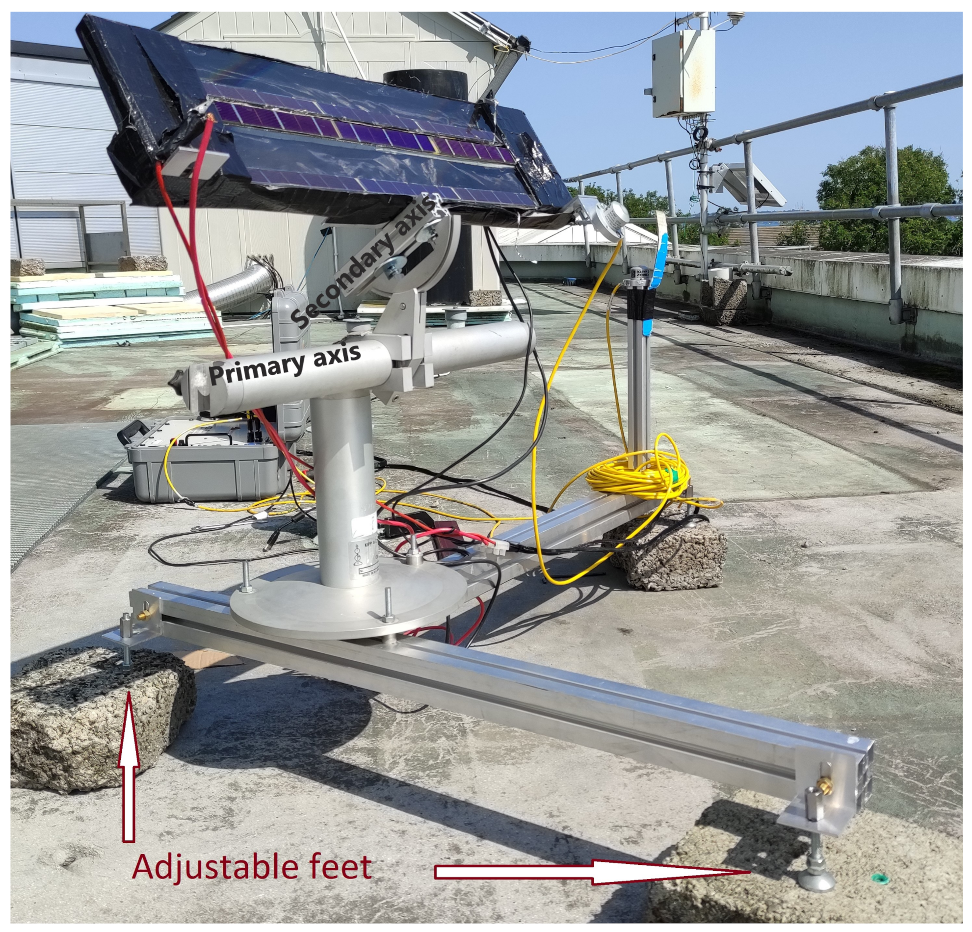
A frame was designed and constructed to adjust the aperture and guide the incident sunlight beam to the surface at the couples of azimuth and altitude angles, as shown in
Figure 3. The frame is adaptable, allowing for tilting around the transverse axis to adjust the azimuth angles and rotation around the longitudinal axis for altering the altitude angles. Due to the symmetrical properties of the lens, the efficiency can be calculated for any direction within the hemisphere above the horizon by establishing the optical efficiencies at the specified zone.
The frame is equipped with adjustable feet to maintain a horizontal position, a swiveling surface for directional adjustments, and two pyranometers to measure the intensity of irradiation. One pyranometer measures the total perpendicular irradiation on the aperture, while the other measures the ambient hemispherical diffusive irradiation. Additionally, the frame includes two individual CoPVG prisms, with PV strips bonded to the focus, as well as an uncovered and identical PV strip placed on the surface.
Figure 2.
Graphical illustration for the experimented incident directions against the aperture surface of the individual lens.
Figure 2.
Graphical illustration for the experimented incident directions against the aperture surface of the individual lens.
Figure 3.
Adjustable frame for evaluating the optical performance of the individual lenses.
Figure 3.
Adjustable frame for evaluating the optical performance of the individual lenses.
Given the linear relationship between the irradiation intensity and the short-circuit current produced in the PV cells [
27],
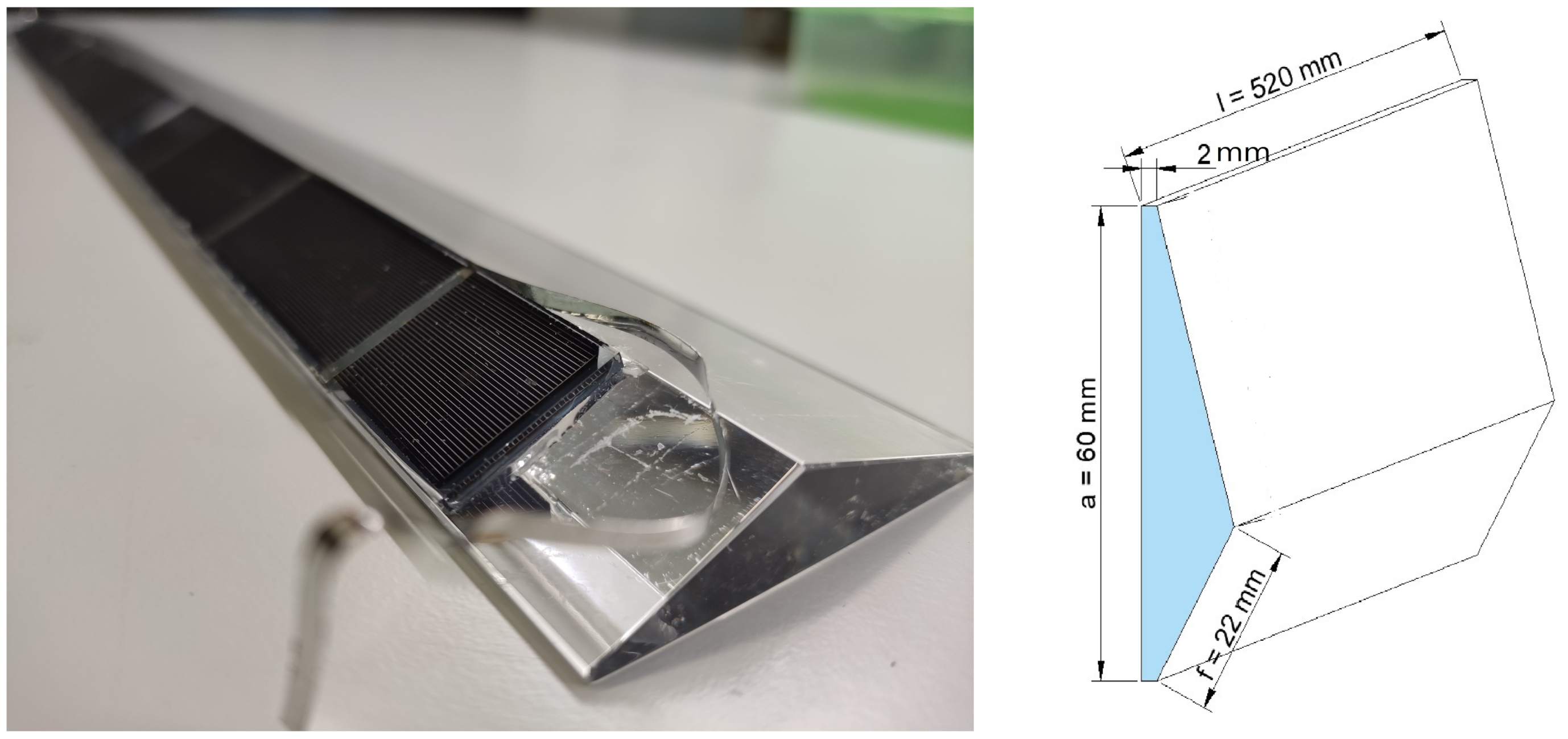
, and the geometry of the individual CoPVG lenses, as shown in
Figure 4, the captured irradiation on the focus and the optical efficiency can be calculated as follows.
Figure 4.
PV cell bonded CoPVG lenses and their geometry.
Figure 4.
PV cell bonded CoPVG lenses and their geometry.
The total hemispherical irradiation intensity is denoted by
G, with
and
representing
G’s respective values on the focus and aperture. A constant value is denoted by
c which relates
G to the short circuit current,
, produced in the PV cells exposing the irradiation intensity.
and
represent the relevant short circuit current values produced in the PV strips mounted on the focus and the reference plane, respectively. The radiative power,
P, is calculated by multiplying the irradiation intensity and the surface area. The geometry coefficient of the lens is the ratio of focus area to aperture area and is represented by
, which is equivalent to
. Here,
f represents the width of the lens focus and
a represents the height of the lens aperture, as shown in the cross-section depicted in
Figure 4.
A Daystar DS-1000 IV-Curve Tracer was utilized to measure the short circuit currents generated in the PV strips, while the incident irradiation intensities were also read from the pyranometers using the tracer. Equation (
2) was then employed to calculate the optical efficiency by the obtained short circuit currents.
During testing and data analysis, several assumptions and considerations were taken into account. These include:
The irradiation intensity remains nearly constant throughout each cycle, although some variations are inevitable. In the event of significant variation, the test is repeated. Any such variations are recorded by measuring the irradiation intensity simultaneously with the short circuits, and the relevant corrections are made accordingly.
The movement of the sun during a single test cycle for each couple of azimuth and altitude angles is negligible. The magnitude of the error depends on several factors, such as the test location, duration, and time. However, a short time interval between adjustments and measurements reduces the error. In order to ensure that the error remains below ±1 for the test location and time, no data were recorded after 5 min from each adjustment.
It should also be noted that there may be errors in the angle adjustments due to inaccuracies in the frame alignment procedure, frame fabrication, and angle measuring precision. These errors are particularly pronounced when the incident beam makes a sharp angle with the aperture, such as when the incident angle is greater than 70.
It is generally recommended to use at least one pyrheliometer and one pyranometer simultaneously to differentiate between the directive and diffusive fractions of radiation. In this experiment, two pyranometers were used. However, it should be noted that there may be errors in calculating the diffusive fraction of irradiation, especially beyond the extremes (i.e., 0 and 90 incident angles), due to the absence of a pyrheliometer.
4. Analytical Solutions
A ray traveling from a semi-transparent medium,
, with a refractive index
to another semi-transparent medium,
, with a refractive index
follows Snell’s law [
28]. Assuming that the surface is purely spectral, then:
The angle of the incidence ray,
, with the unique normal vector of the interface on the other side of the surface, −
, is denoted by
, while the angle of the transmitted ray,
, with −
is denoted by
. If the refractive index of the first,
, is greater than that of the second medium,
, the angle of incidence will reach a critical value,
, as the incident angle,
, increases. For angles greater than
, the ray will not transmit into the second medium but instead will be reflected into the first medium at the same angle of incidence, in the same plane but on the other side of the irradiation. This phenomenon is known as
. The direction of the reflected ray,
, is given by the following equation.
At incident angles below
, a fraction of the incident irradiation is reflected into the first medium, with the reflected ray direction being calculated by Equation (
4). In this domain, the internal reflective fraction is a function of
,
, and the refractive index of both media. This fraction can be calculated using the following equation [
28].
Furthermore, the incident radiative energy passing through a medium may undergo absorption or scattering within the medium, as described by the following equation [
29].
The absorption and scattering coefficients of the medium are denoted by and , respectively, and x represents the distance that the ray travels within the medium. The intensity of the direct component of light () is defined as the fraction of the initial intensity () that remains after traversing a distance x within the semi-transparent medium.
The aforementioned discussion forms the foundation for understanding the transmission of light rays from one semi-transparent medium to another and within the domain. However, it is important to note that when investigating such transmissions, a portion of the incident radiation is absorbed and/or reflected at the surface either spectrally or diffusively, depending on the boundary conditions of the wall or PV cell under consideration in the experiment.
To account for all relevant parameters, it is crucial to perform a computation using the finite element method. However, in the present paper, the experimental observations are compared with an analytical model developed at Ulster University. This model provides a comprehensive analysis of line-axis concentrators, taking into account the reflection, refraction, and absorption of rays that interact with the concentrator. The ray tracing method is employed to simulate the behavior of the concentrator components in response to sunlight, by specifying a particular number of rays that are evenly distributed across the aperture of the system.
The analytical solution employed in this study is based on the following assumptions:
The light is purely directional.
All surfaces are assumed to be spectral, thus the impact of diffusive reflection/transmission is neglected.
The scattering coefficient of the lens is assumed to be zero.
The light that reaches the absorber is assumed to be completely absorbed. Accordingly, the absorptivity of the PV cell is taken to be 1.0, acknowledging that a fraction of the rays that impinge on the absorber are reflected into the domain, primarily in a diffusive manner. However, the contribution of the reflected ray from the PV cell is deemed negligible.
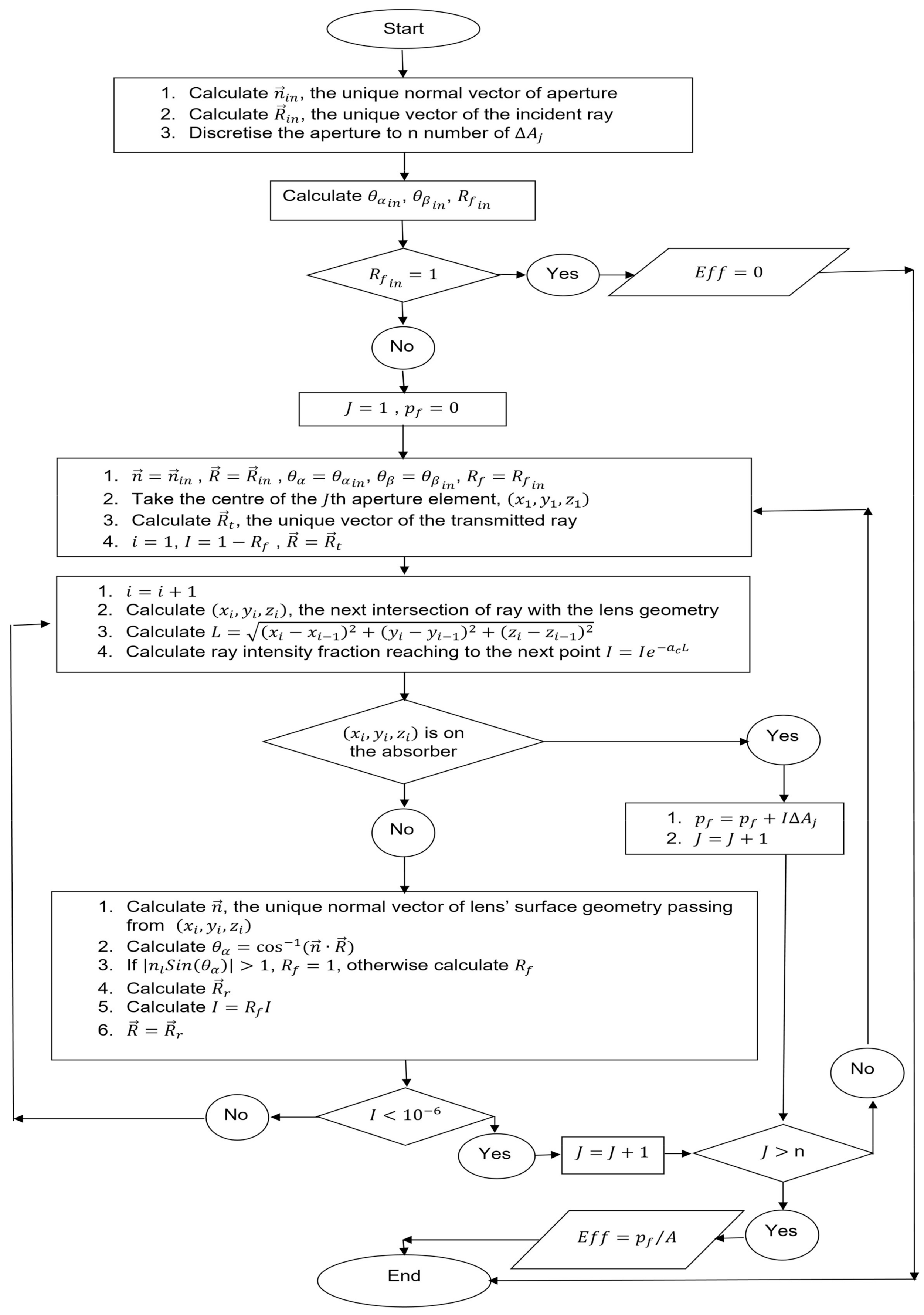
Considering the above assumptions, the analytical solution can be summarized in the flowchart presented in
Figure 5.
5. Results
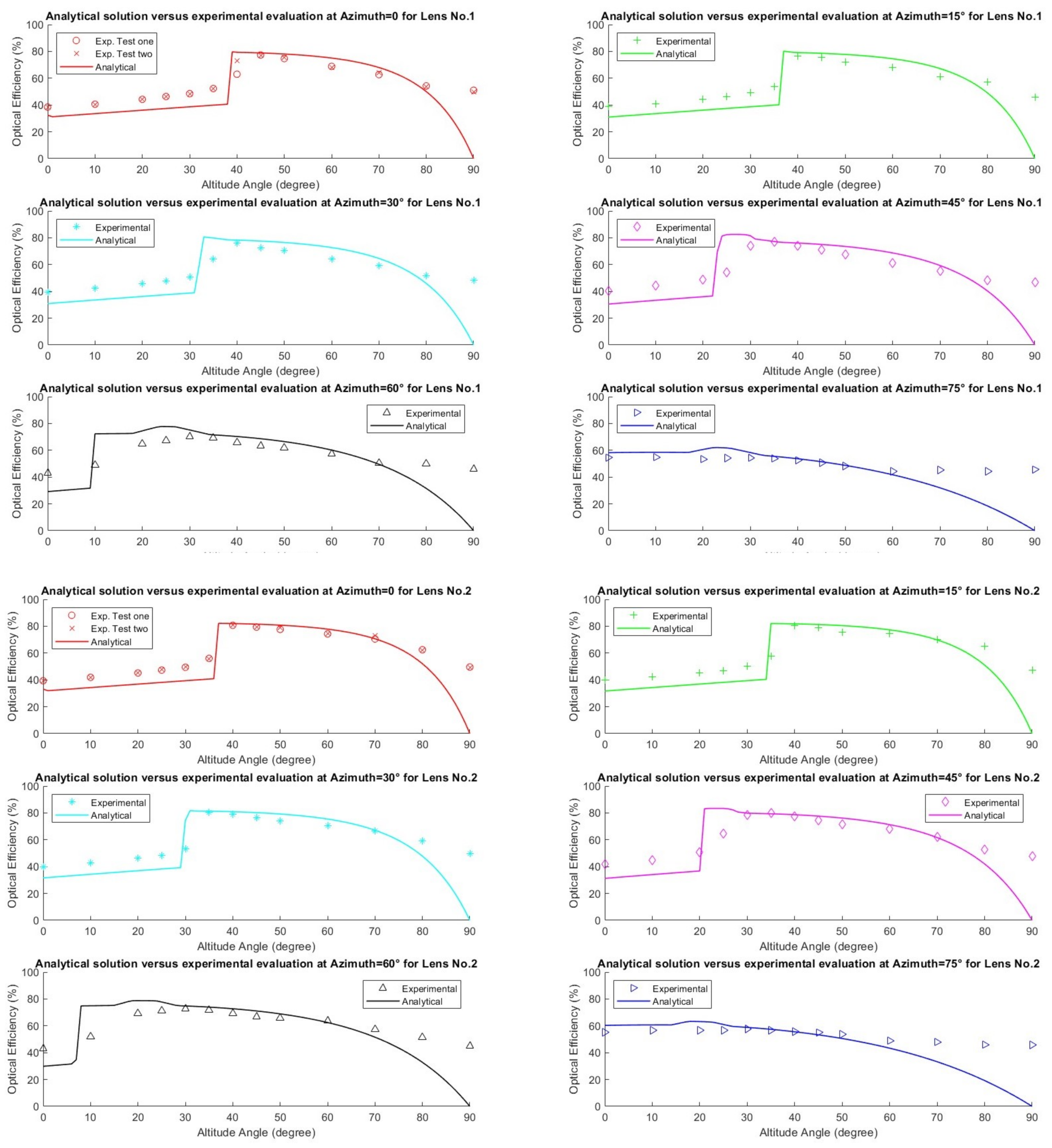
Figure 6 presents the results and compares the optical efficiency calculated analytically and experimentally at various azimuth angles. The findings are consistent in identifying the switching angle and the occurrence of TIR. However, below the switching angle, there are discrepancies between the experimental and analytical results, with the former demonstrating higher optical efficiency. Above the switching angle, the results are more comparable, albeit the experimental data rarely surpass the analytical results, except for sharply incident angles (i.e., incident angles greater than 70
), where the optical efficiency tends to be higher in the experiments.
6. Discussions
The discrepancy between the experimental and analytical results below the switching angle could be attributed to the omission of the diffuse fraction of irradiation in the analytical solution. It is worth emphasizing that both the direct and diffuse fractions of irradiation contribute to the concentrated irradiation at the focal point of the lens, and hence its optical efficiency. Consequently, the following equation can be derived.
In this equation,
represents the total concentrated irradiation on the focus area,
. The parameters
and
correspond to the contributions of the direct and diffuse fractions of irradiation, respectively, on the aperture, with the surface area of
A, that are concentrated on the focus. The quantities
and
denote the direct and diffuse irradiation intensities perpendicular to the aperture, respectively. While
The optical performance can be derived as:
Taking
results in
from Equation (
8). Thus:
The variable F in the above equation denotes the fraction of normal incident irradiation on the aperture that is diffusive. The equation highlights the discrepancy between the analytical and experimental optical efficiency values, as discussed in this context. Moreover, they emphasize the importance of taking into account the diffuse component of radiation when calculating the optical and electrical performance of the system.
The following statements provide support for the idea of incorporating the diffuse component of radiation.
First, at an altitude of 90
, the normal direct irradiation component is zero, as shown in Equation (
9). Consequently, the diffusive fraction of irradiation is equal to 1. Under these conditions, while the analytical model predicts an optical efficiency of zero, the contribution of the diffusive irradiation is significant. In other words,
The parameter , which represents the contribution of the diffusive fraction of irradiation on the aperture to the concentrated irradiation on the focal point, is a characteristic of the lens that can be evaluated from experimental data. By determining the optical efficiency at an altitude of 90 for various azimuths and lenses, the average value of for CoPVG lenses was found to be 0.48, indicating that 48% of the diffusive radiation on the aperture reaches the focus. It should be noted, however, that this characteristic is influenced by factors such as lens geometry, material, and surface quality.
Next, the contribution of the diffusive fraction of irradiation is neglected in the analytical solution. Therefore
That means is equivalent to the analytically calculated optical efficiency.
Then, the experiment verifies that the value of F lies between 0.10 and 0.30 during the test conducted below the switching angle, which results in the contribution of diffusive irradiation. For instance, based on the experimental data obtained at azimuth and altitude zero for lens number one, where , the analytically calculated optical efficiency can be corrected as follows.
from the first statement
from the second statement and output of the analytical solution
Thus Optical Eff. =
, from Equation (
11), which tends to more closely resemble the experimentally determined value at 0.38.
Finally, in cases where the altitude angle surpasses the switching angle, the diffusive fraction of irradiation rises because of the increased value of
, with, for instance,
F equal to or greater than 0.3. As a result, Equation (
11) is utilized to adjust the analytical solution accordingly. For instance, when the altitude is in proximity to the switching angle, the analytical model predicts values that are close to 0.8, while the diffusive contribution, which is 0.48, lessens the total optical efficiency. Thus, the experimental evaluation of the optical performance rarely surpasses the analytical solutions, as depicted in
Figure 6. In contrast, when incident angles are above 70
, and
F is 0.8 or higher, the diffusive contribution becomes the primary factor that prevents the total optical efficiency from decreasing rapidly, as predicted by the model.
In summary, it is noteworthy that the optical efficiency of the CoPVG lenses is slightly higher than the model prediction when the sun location is below the switching angle due to the presence of natural diffusive irradiation. However, the discrepancy is proportionate to the diffusive fraction of irradiation, which varies over time. Moreover, the difference between the experimental results and the analytical model is insignificant above the switching angle, up to an incident angle of 70. Furthermore, the glazing function is more of interest in a clear-sky condition when the diffusive fraction is negligible. Therefore, despite the discrepancies, the model is conservative and reliable in predicting the optical efficiency of the CoPVG lenses, except when the incident angle approaches 90, due to the significant participation of the diffusive fraction of irradiation at those incident angles.
7. Case Study
To take advantage of the seasonal effects of CoPVG, the shape of the lens should be designed based on a building’s location. To accomplish this, it is necessary to analyse the optical performance. The analytical model’s resemblance with the experimental results allows for its utilization in conducting the analysis. The current section focuses on figuring out how the glazing responds to the sun’s seasonal positioning in the sky based on the output of the analysis. Additionally, this section presents the advantages of utilizing CoPVG compared with traditional STPV glazing as an output of the analysis.
7.1. CoPVG Optical Performance
This subsection highlights the benefits of assessing the optical efficiency of lenses with respect to solar positioning. This study demonstrates the seasonal effect of the CoPVG lens in a building situated in Belfast, UK, as an example to demonstrate the practical application of this method. However, the position of the sun may differ in other locations. Nevertheless, the same methodology can be applied.
By understanding how the glazing reacts to the sun’s positioning in the sky, it is possible to optimize the design of the lens and maximize its performance. This can lead to energy savings and improved comfort levels for building occupants. In other words, the analysis facilitates tailoring the design to maximize efficiency while balancing the need for natural lighting and energy generation.
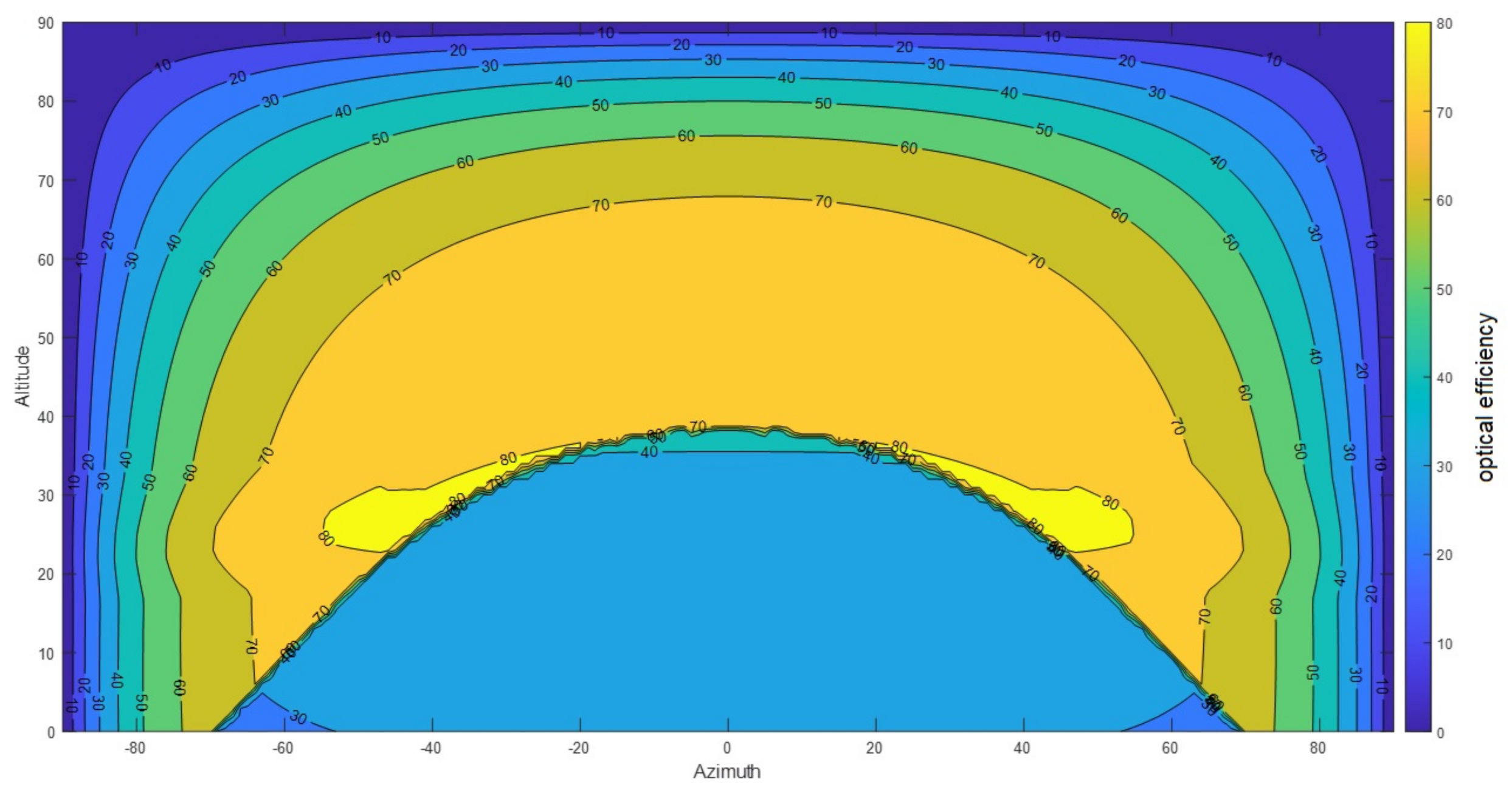
Figure 7 presents the optical efficiency of the CoPVG lens in solar coordination, which is known as the optical map, as determined through the analytical model. The optical map is a valuable resource for improving the design of the CoPVG lens, as it provides insights into the optical reaction of the lens.
The map is dependent on the lens geometry and material properties, which should be adjusted for the purpose of balancing the lighting and energy needs. The map shows a substantial increase in optical efficiency from 40% to 80%, as indicated by the switching angle line graph. When the sun is positioned below the switching line, the primary function of the glazing is to transmit sunlight and provide natural daylight to the building’s interior. Conversely, when the sun is located above the curve, the glazing will concentrate the irradiation at the focus to improve electricity generation, while simultaneously blocking excessive glare to ensure occupant comfort.
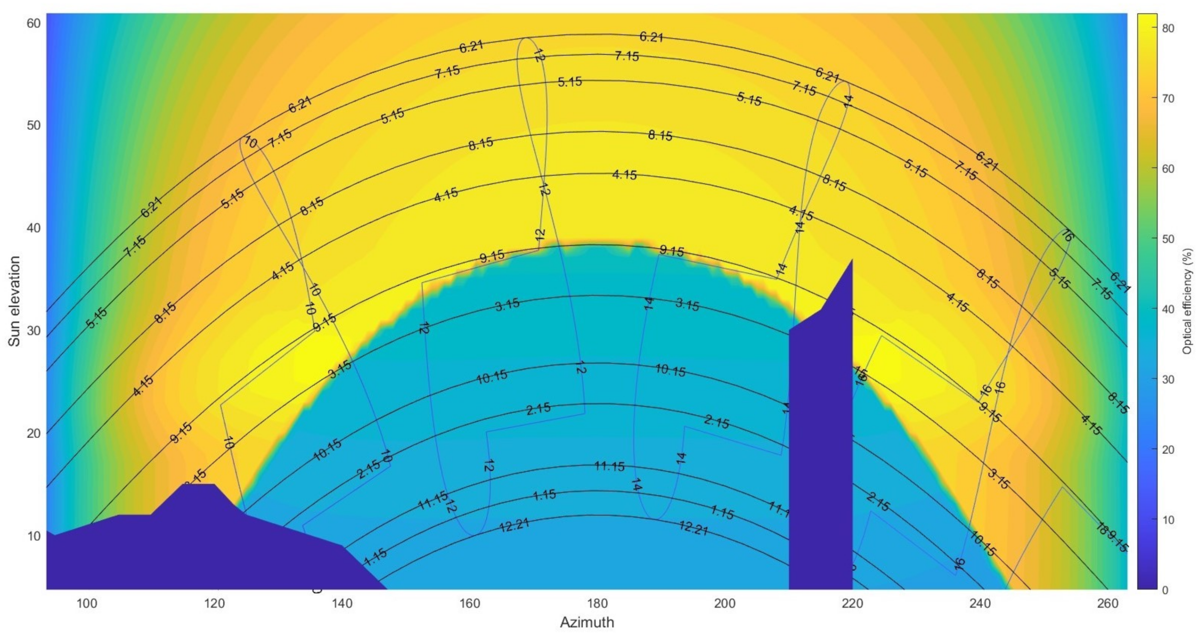
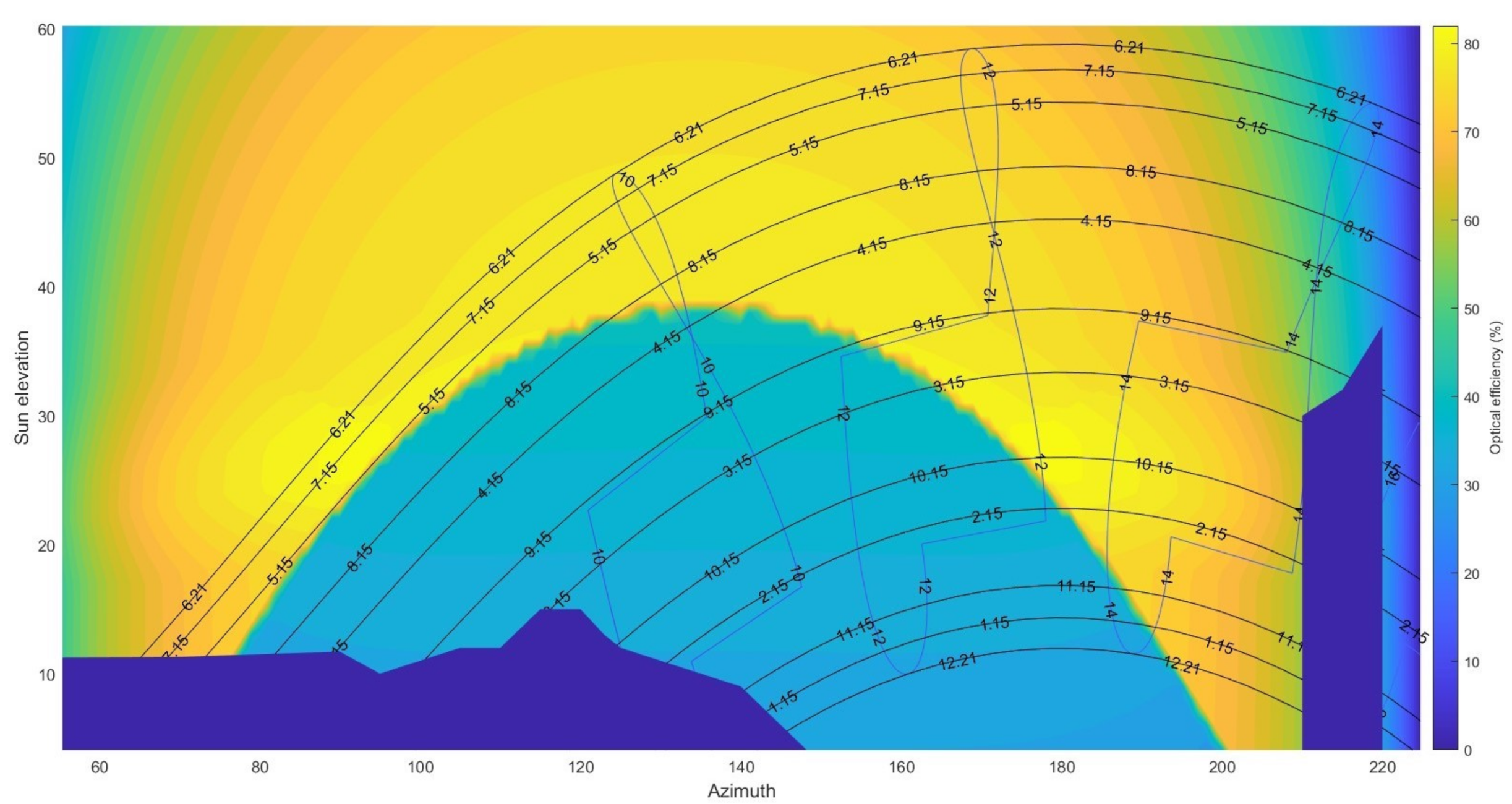
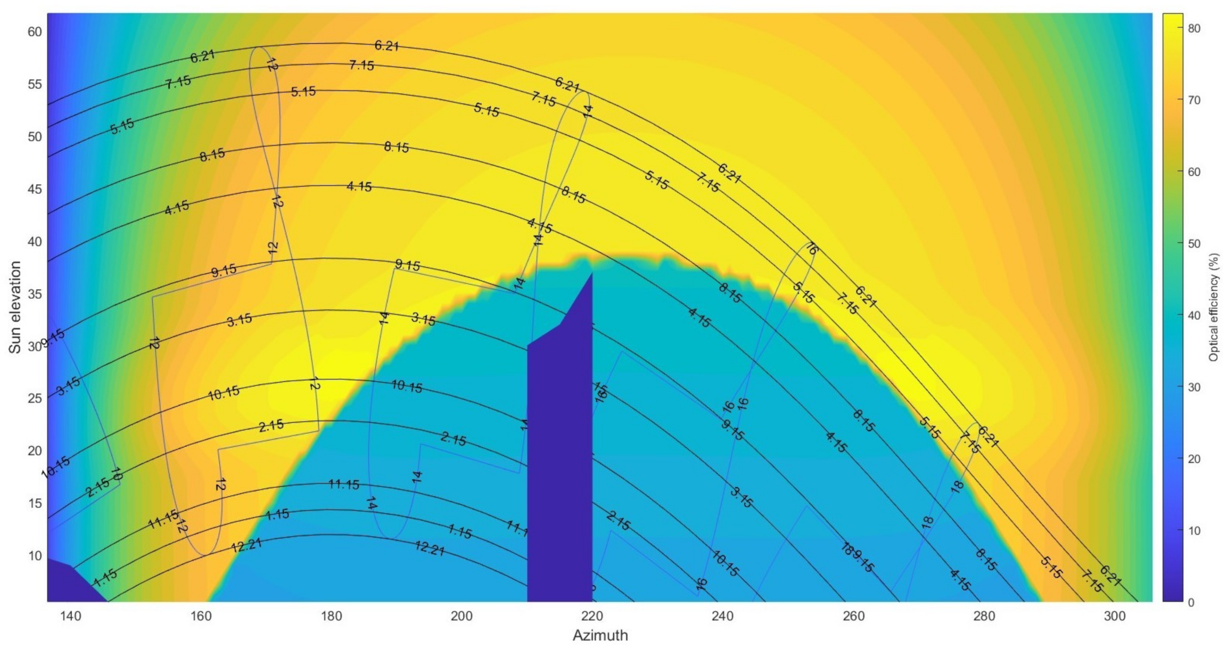
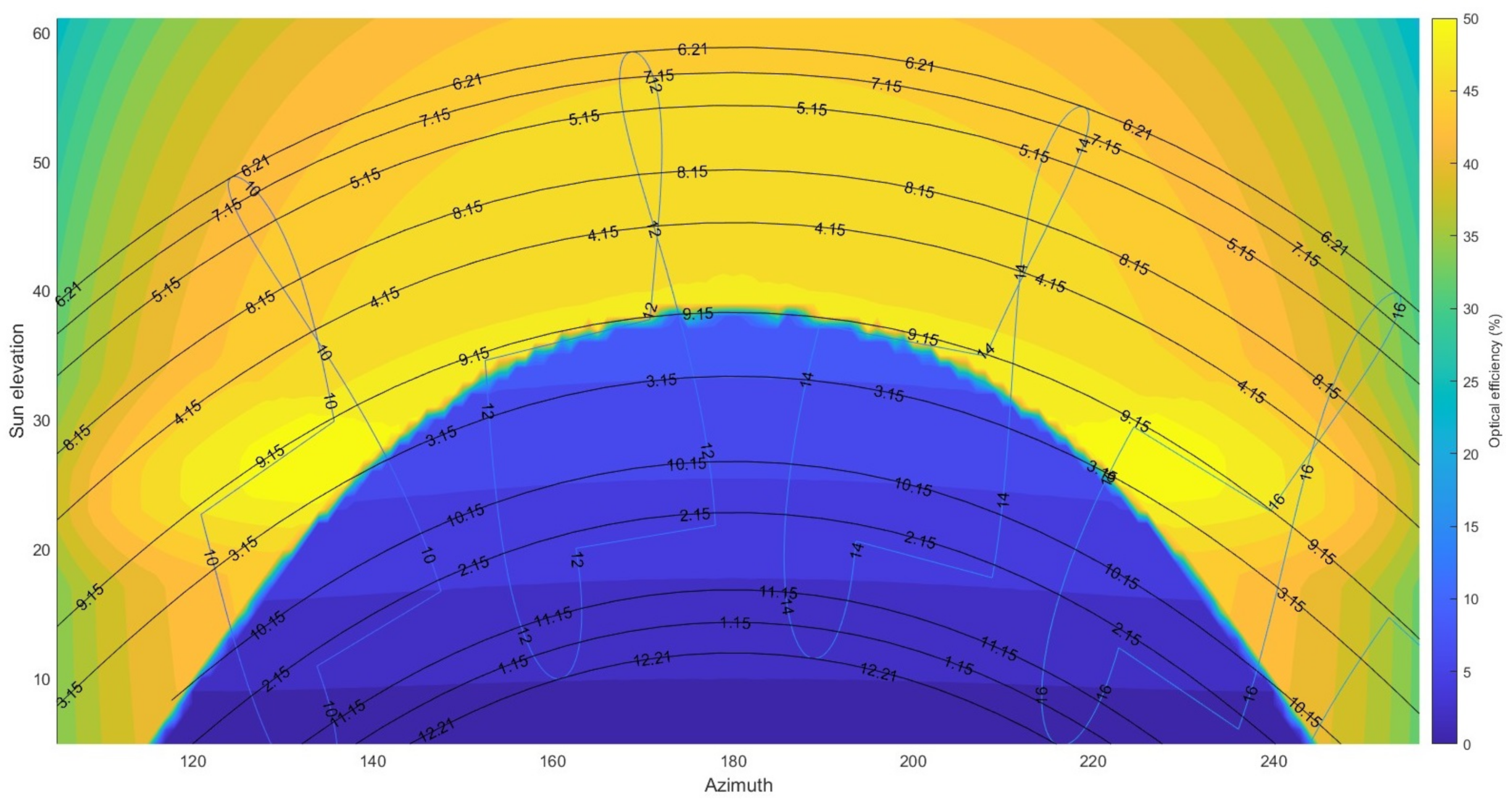
This study incorporates three fundamental aspects of the glazing’s properties to provide a comprehensive understanding of its optical performance; the optical map, the annual position of the sun in the sky illustrated in date and hour contours reflecting the building’s geographical location, and the profile of the surrounding obstacles representing the building’s ambient characteristics. By combining these three factors, a thorough analysis of the optical performance of the glazing can be conducted.
Taking into account the impact of surrounding obstacles such as a tower in the southwest and a distant mountain in the east, the analysis was conducted for three different orientations of the glazing, with
Figure 8,
Figure 9 and
Figure 10 depicting the optical performance of the lens for each orientation. The dark blue regions on the graphs indicate areas where obstacles block the sun, resulting in no sunlight reaching the glazing during those times throughout the year.
The presented figures provide insights into the seasonal effect of the CoPVG glazing in the case study. For instance,
Figure 8 indicates that the installation of the glazing towards the south leads to a shift in its performance from room lighting to shading on April 1st, and vice versa on September 15th. The other figures can be interpreted accordingly.
Additionally, the figures can be used to anticipate the electrical output power of the glazing by providing the irradiation intensity on the glazing at any time throughout the year. For instance, the graph indicates that 78% of irradiation on the glazing reaches the focus on April 15th from 11 a.m. to 2 p.m. If the average irradiation intensity on the glazing is maintained at 800 W/m, the irradiation on the focus will reach 1700 W/m, and the output electrical power of c-Si PV cells with 20% efficiency bonded on the focus is estimated at 7.5 W per meter length of the PV cell in the focus or 125 W/m glazing surface, theoretically. The electrical efficiency of the glazing would be 15.6% in this case.
7.2. Enhancements in the Optical Efficiency of the Glazing
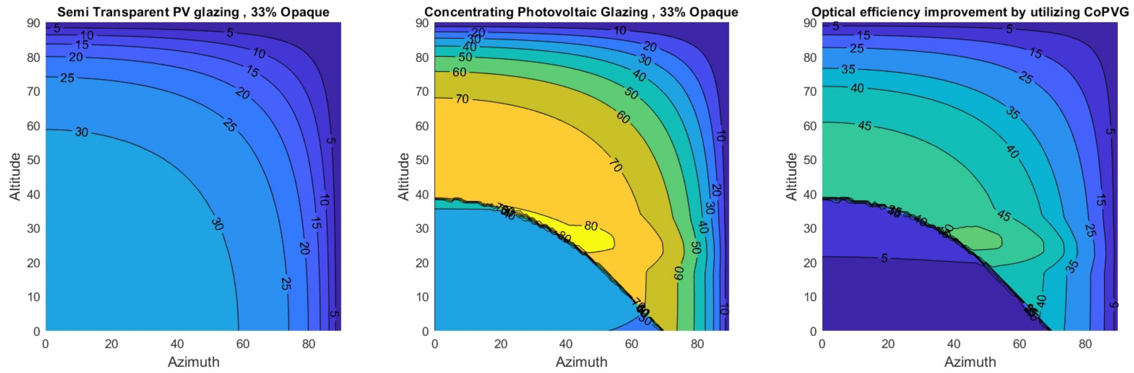
This subsection outlines the benefits of employing CoPVG lenses compared to traditional STPV glazing. As the glazing becomes 33% opaque with the application of the CoPVG lenses, a comparison is made between the device and traditional STPV glazing with longitudinal PV strips covering 33% of the surface area.
Figure 11 demonstrates the optical efficiency of traditional STPV glazing in solar coordination within a quarter of the hemisphere above the ground. The optical efficiency of the relevant CoPVG and the improvement achieved by utilizing the CoPVG lenses are depicted as well. The analyses show that the optical efficiency of STPV glazing is limited to 33%, with a maximum value of 32.97% from the model. In contrast, the optical efficiency of the CoPVG lens varies depending on the beam direction with a maximum of 83.40%. Further, the enhancement varies from zero to more than 52%, accordingly. The advantage of utilizing CoPVG compared to STPV glazing can be interpreted by the location of the radiation source, i.e., the sun.
Figure 12 depicts the performance improvement achieved by implementing CoPVG lenses instead of the relevant STPV glazing in the building and the glazing mounted on a south-facing window. While the improvement does not exceed 10%, typically ranging between 5% and 8% during winter, it reaches a maximum of 52.3% in summer. During the most crucial hours for harvesting electricity, which is between 10 am and 3 pm, the CoPVG lens enhances the optical efficiency of the glazing from 46% up to 52% from early April to mid-September. As the optical efficiency is directly related to the electricity power harvesting potential, the same improvement is expected in electricity generation when implementing CoPVG lenses.
8. Conclusions
An experimental campaign was carried out to assess the optical efficiency of the CoPVG device and to validate an analytical model developed at Ulster University. The experimental results revealed discrepancies between the model’s predictions and the actual results, which can be attributed to the simplified assumptions made in the model, particularly the neglect of the diffuse fraction of irradiation. To account for this, a mathematical equation was proposed to include the effect of diffuse light and explain the observed discrepancies. The study concluded that the optical efficiency of the system may be decomposed into two independent factors: and , which represent the contributions of the direct and diffuse fractions of irradiation, respectively.
The variable is equivalent to the analytical model outputs, while requires experimental evaluation. It is possible to calculate using finite element methods as well. In the present study, was determined through experimental measurements and was found to be 0.48 for the CoPVG lenses, indicating that 48% of the diffusive radiation incident on the aperture is focused on the focal point. It should be noted that the diffusive fraction of irradiation is subject to natural variability over time.
Despite its limitations, the analytical model still offers a useful overview of the optical performance of the device. This is because of the interest in the glazing functionality in clear-sky conditions when the diffusive fraction of light is negligible. The optical performance of the device is characterized by the optical map, which represents the optical efficiency variation presented in solar coordination. The optical map is employed to generate a visual representation of the glazing’s optical performance over the course of a year, considering the location of the building, the glazing orientation, and the ambient solar obstacles.
The above investigation offers significant insights into the performance of the lens, which in turn facilitates the balancing of natural lighting and energy generation requirements. A case study of a building located in Belfast was presented as an example of how the model can be utilized to easily evaluate the glazing’s annual optical performance. The study revealed that utilizing the glazing toward the south will result in a shift in the glazing function from room lighting to shading on April 1st, and vice versa on 15 September. Furthermore, the glazing improves the electrical power harvesting potential between 5% to 8% and 46% to 52% in winter and summer, respectively, when compared with traditional spaced-type STPV glazing with the same opaque area percentage.

 ,
, 


