Article

Investigating the Influence of Groundwater Flow and Charge Cycle Duration on Deep Borehole Heat Exchangers for Heat Extraction and Borehole Thermal Energy Storage

James Watt School of Engineering, University of Glasgow, Glasgow G12 8QQ, UK
*
Author to whom correspondence should be addressed.
Energies 2023, 16(6), 2677; https://doi.org/10.3390/en16062677
Submission received: 2 March 2023 / Revised: 8 March 2023 / Accepted: 9 March 2023 / Published: 13 March 2023
(This article belongs to the Special Issue Advances in Underground Thermal Energy Storage)

Abstract

:
Decarbonisation of heat is essential to meeting net zero carbon targets; however, fluctuating renewable resources, such as wind or solar, may not meet peak periods of demand. Therefore, methods of underground thermal energy storage can aid in storing heat in low demand periods to be exploited when required. Borehole thermal energy storage (BTES) is an important technology in storing surplus heat and the efficiency of such systems can be strongly influenced by groundwater flow. In this paper, the effect of groundwater flow on a single deep borehole heat exchanger (DBHEs) was modelled using OpenGeoSys (OGS) software to test the impact of varying regional Darcy velocities on the performance of heat extraction and BTES. It is anticipated that infrastructure such as ex-geothermal exploration or oil and gas development wells approaching the end of life could be repurposed. These systems may encounter fluid flow in the subsurface and the impact of this on single well deep BTES has not previously been investigated. Higher groundwater velocities can increase the performance of a DBHE operating to extract heat only for a heating season of 6 months. This is due to the reduced cooling of rocks in proximity to the DBHE as groundwater flow replenishes heat which has been removed from the rock volume around the borehole (this can also be equivalently thought of as “coolth” being transported away from the DBHE in a thermal plume). When testing varying Darcy velocities with other parameters for a DBHE of 920 m length in rock of thermal conductivity 2.55 W/(m·K), it was observed that rocks with larger Darcy velocity (1e-6 m/s) can increase the thermal output by up to 28 kW in comparison to when there is no groundwater flow. In contrast, groundwater flow inhibits single well deep BTES as it depletes the thermal store, reducing storage efficiency by up to 13% in comparison to models with no advective heat transfer in the subsurface. The highest Darcy velocity of 1e-6 m/s was shown to most influence heat extraction and BTES; however, the likelihood of this occurring regionally, and at depth of around or over 1 km is unlikely. This study also tested varying temporal resolutions of charge and cyclicity. Shorter charge periods allow a greater recovery of heat (c. 34% heat injected recovered for 1 month charge, as opposed to <17% for 6 months charge).

1. Introduction

In order to meet net zero carbon emission targets and curb global warming, it is essential to decarbonise heat. Renewable energy can provide alternative sources of heat; however, supply can fluctuate due to seasonality or irregular weather patterns, which often do not match periods of high demand. Therefore, methods of thermal storage must be considered to store energy in low-demand periods (summer) that can be utilised during high-demand periods (winter). While many underground thermal energy storage technologies exist, this paper considers the potential use of BTES in repurposed deep wells, either from ex-geothermal exploration wells or oil and gas wells approaching end of life.
Many have considered the use of DBHEs exploiting energy in closed-loop geothermal systems (e.g., [1,2,3,4,5,6]), with some looking at the potential of repurposed oil and gas wells (e.g., [7,8,9]), or ex-geothermal exploration wells (e.g., [10,11,12,13]). Yet, few have investigated the potential to repurpose DBHEs for BTES. Those that do have investigated systems which rely on conductive heat transfer only in the subsurface, neglecting the influence of groundwater flow (see Figure 1), which can be common in the shallow subsurface or in deeper reservoirs. In shallow to medium depth BTES arrays, this has been proven to be an important factor influencing storage efficiency (e.g., [14,15]). In particular for the UK, it has been shown that there is a strong potential for groundwater flow to occur in deep Permo-Triassic aquifers [16,17].
Xie et al. [18] tested 5 parameters for a single well BTES system in a repurposed oil and gas well. They concluded the most influential parameters, in order, were inlet temperature during extraction, inlet temperature during charge, flow rate and geothermal gradient. Further work from Brown et al. [11] built on this idea, but for the repurposing of an ex-geothermal exploration well, testing 10 parameters and defining a new metric for storage efficiency. They concluded that the most influential parameters based on rankings of the global sensitivity analysis were inlet temperature during charge, inlet temperature during extraction, flow rate and geothermal gradient. When using the new metric defined in the study by Brown et al. [11], the authors demonstrated that deep borehole heat exchangers struggle to achieve a storage efficiency of greater than 17% (where storage efficiency is defined as increase in output from a DBHE as a fraction of heat injected) for 6 month charge/discharge cycles. In light of this, DBHEs appear to be not optimum candidates for BTES, unless there are no other viable uses for surplus heat and the construction of other forms of thermal energy storage are economically unviable. Both the aforementioned studies of Xie et al. [18] and Brown et al. [11] provide useful analysis when determining the potential of such systems; however, they neglect the influence of groundwater flow and do not consider the longevity or varying periods of charge on such systems. Therefore, this study aimed to bridge this gap by considering the most influential parameters (flow rate, inlet temperature during extraction and inlet temperature during charge) with varying levels of groundwater flow. Long term simulations were then undertaken to consider the efficiency of BTES over several cycles of operation of a single well DBHE.
In this study, the Newcastle Science Central Deep Geothermal Borehole (NSCDGB) was considered as a case study as plans are in place to repurpose this for testing as a pilot DBHE in the UK (study area highlighted in Figure 2). It is a former geothermal exploration well that encountered low-permeability strata within the Carboniferous Fell Sandstone Formation at depths in excess of 1400 m [19]. It was initially identified as a geothermal prospect due to the geothermal heat flux and elevated geothermal gradient associated with the deeply concealed radiogenic North Pennine Batholith [20,21]. Groundwater conditions in the target reservoir (the Fell Sandstone) were not extensively tested, although very low permeability (~8.1 × 10⁻¹⁰ m s−1) was inferred from the lack of appreciable fluid yield from the borehole [19]. Nevertheless, groundwater was identified during well drilling at higher stratigraphic levels in the well [19]. Therefore, the influence of groundwater movement on extraction and BTES was tested in this study using a modelling approach. OGS software uses the finite-element method for spatial discretisation and has been verified/validated against a series of solutions for shallow and DBHE examples (e.g., [10,12,22,23,24,25]). Further benchmarking was also undertaken in this study in comparison to T2Well-EOS1/TOUGH2. The ‘Dual Continuum’ method is used to model the wellbore, with components of the DBHE (grout, fluid, casing) treated as a 1D line source, integrated within a 3D medium for the subsurface rocks.
This work has further universal implications for DBHEs operating to extract heat only, as previous work has suggested the influence of groundwater flow is minimal when thin aquifers are present [23]; however, this work investigates the presence of large-scale groundwater flow over the length of the DBHE. Groundwater flow was modelled as a regional Darcy velocity (groundwater flow per unit perpendicular cross-sectional area of aquifer), which is defined as the product of hydraulic conductivity and hydraulic gradient. Locally to the UK, low-enthalpy Mesozoic Basins, such as the Cheshire and Wessex Basins, have large thicknesses of sandstones up to 2 km thick (Knutsford-1 well in the Cheshire Basin—see [26]) and a high geothermal potential (e.g., [27,28,29,30,31]). Future geothermal exploration wells or oil and gas wells approaching end of life (e.g., [32,33]) may be considered for repurposing as a DBHE for heat extraction or BTES. These will penetrate large quantities of aquifers with advective regimes which must be considered. Results from this study will therefore be beneficial in any decision making in repurposing of wells in areas of thick aquifer concentrations.
To summarize, the objectives of this paper were (i) to model regional groundwater flow for deep borehole heat exchangers for both heat extraction and BTES, (ii) to test the impact of charge-discharge cycle duration on storage efficiency and (iii) to understand if operational duration has an impact on the performance of single well deep BTES.

2. Methods

2.1. Governing Equations

OGS software was used to simulate BTES in a single DBHE. The mesh was spatially discretised using the finite-element method which incorporates a ‘dual-continuum’ approach which treats the DBHE as a 1D line source and the surrounding rock as a 3D mesh (Figure 3). In this study, the model used a CXA configuration (coaxial pipe with annular inlet) (Figure 1) as previous work shows the influence of flow direction (i.e., inlet through the annulus versus the central pipe) has minimal impact on DBHEs [11]. In the CXA configuration, fluid is circulated down the annular space, exchanging heat or coolth with the subsurface via conduction through the borehole wall, before being circulated back to the surface through the central pipe. Groundwater flow in the subsurface was modelled using a constant regional Darcy velocity ( v f ) (Equation (1)) (see [34] for methods of modelling groundwater flow), which is a common approach in similar studies for shallow arrays (e.g., [35,36]). It is worth noting that this is unlikely to replicate the true subsurface hydrogeological conditions at the NSCDGB, but will help to improve the understanding of the impact of groundwater flow for DBHEs and deep BTES.
The DBHE was modelled with a simplified single grout layer and casing. Four governing equations model heat transfer within (1) the rock formation, (2) the grout, (3) the borehole casing and (4) the central coaxial pipe. The governing equation in the rock is given by the energy balance (e.g., [22,23]):
t [ ϕ ρ f c f + ( 1 ϕ ) ρ r c r ] T r + ( ρ f c f v f T r ) ( Λ r T r ) = H r
where ϕ is the effective porosity, ρ r is the matrix density of the rock, ρ f is the density of the circulating fluid, T r is the temperature of the saturated rock, c r is the matrix specific heat capacity of the rock and c f is the specific heat capacity of the fluid. H r is the source term and Λ r is the thermal hydrodynamic dispersion tensor, which depends on the bulk thermal conductivity of the rock λ r . A heat flux ( q n T r ) boundary condition was adopted between the DBHE and surrounding rock:
q n T r = ( Λ r T r )
Conductive heat transfer dominates the thermal regime within the grout:
( 1 ϕ g ) ρ g c g T g t [ ( 1 ϕ g ) λ g T g ] = H g
where the subscript g represents the grout. In the annular space (i.e., inlet, subscript i ) and central coaxial pipe (i.e., outlet, subscript o ), heat transfer is governed by advection:
ρ f c f T i t + ρ f c f v i T i ( Λ f T i ) = H i
ρ f c f T o t + ρ f c f v o T o ( Λ f T o ) = H o
where v i and v o are the inlet and outlet fluid velocity vectors, respectively. Λ f represents the hydrodynamic thermo-dispersion tensor which in this example can be simplified to equal the fluid thermal conductivity ( λ f ).
The horizontal thermal resistance to heat flow within the DBHE was modelled as an analogue to a resistor network (e.g., see [37]). Thermal resistance for heat flow was modelled between (a) the rock and grout ( R g r ), (b) the grout and borehole casing ( R f i g ) and (c) the borehole casing and the central coaxial pipe ( R f f ). Using the outer surface area at the relevant interface, the thermal resistances can be expressed as heat transfer coefficients ( Φ ) which appear in the boundary conditions for the grout, borehole casing, and central coaxial pipe. The boundary condition for Equation (3) can be expressed as:
q n T g = Φ g r ( T r T g ) Φ f i g ( T i T g )
In a similar procedure, the boundary conditions for Equations (4) and (5) can be expressed respectively as:
q n T i = Φ f i g ( T r T i ) Φ f f ( T o T i )
q n T o = Φ f f ( T i T o )
The heat transfer coefficients in Equations (6)–(8) are a function of the borehole casing diameter ( d c a sin g ), the central coaxial pipe diameter ( d c e n t r a l ), and the borehole diameter ( D b ). The heat transfer coefficients can be given by: Φ g r = 1 / R g r π D b , Φ f i g = 1 / R f i g π d c a sin g , and Φ f f = 1 / R f f π d c e n t r a l . See, for example [38], on how to compute the thermal resistances.

2.2. Model Set Up, Initial Conditions and Parameterisation

Under initial conditions, a linear geothermal gradient (33.4 °C/km) was established, increasing with depth. This is in line with those values recorded at the wellsite and modelled in the literature (e.g., see [19,20,21,30,39,40]). The surface temperature was set at a fixed constant Dirchlet boundary corresponding to 9 °C and the remaining lateral and basal boundaries were fixed as Neumann no-flow boundaries with heat flux set equal to zero. Under initialisation of the simulation, all wellbore components (grout, pipe, fluid) were set to equal initial conditions (i.e., increase with depth under the natural geothermal gradient). Lateral and basal boundaries of the model were set to extend to a distance where thermal interaction with the DBHE would be minimal (and not occur). For the setup of groundwater flow, a constant Darcy velocity was established in the x direction throughout the model. Finally, the domain size was set at 500 × 500 × 1300 m (x, y, z) (Figure 3).
The base case model parameters are listed in Table 1 and have been collected from in-situ data or literature. The geology was modelled as a homogenous rock and the subsurface parameters (i.e., density, specific heat capacity and thermal conductivity) listed are the bulk saturated properties for the rock taken as a weighted average through the vertical dimension of the model [10]. The initial inlet temperature during charge was fixed at 95 °C, whilst during extraction it was fixed at 5 °C. An initial extraction and charge period of 6 months was used, which corresponds to the typical heating season in the UK.
Further parameters tested throughout the study are highlighted in Table 2. The groundwater flow velocity was considered typical in shallow aquifers and is consistent with aquifer values reported in the literature (e.g., [35,41]). The regional groundwater flux was applied to the Darcy velocity in Equation (1). For context, a Darcy velocity of 1e-7 m/s results from a hydraulic conductivity of 1e-5 m/s (or 0.9 m/d, corresponding to a reasonably clean poorly lithified sand or sandstone aquifer) and a hydraulic gradient of 1% [36]. It is worth noting that the higher Darcy velocities modelled are more likely to be encountered in shallower settings rather than deep, but were considered in this study as a maximum upper limit of groundwater flow for more universal applications.

2.3. Evaluation Metrics
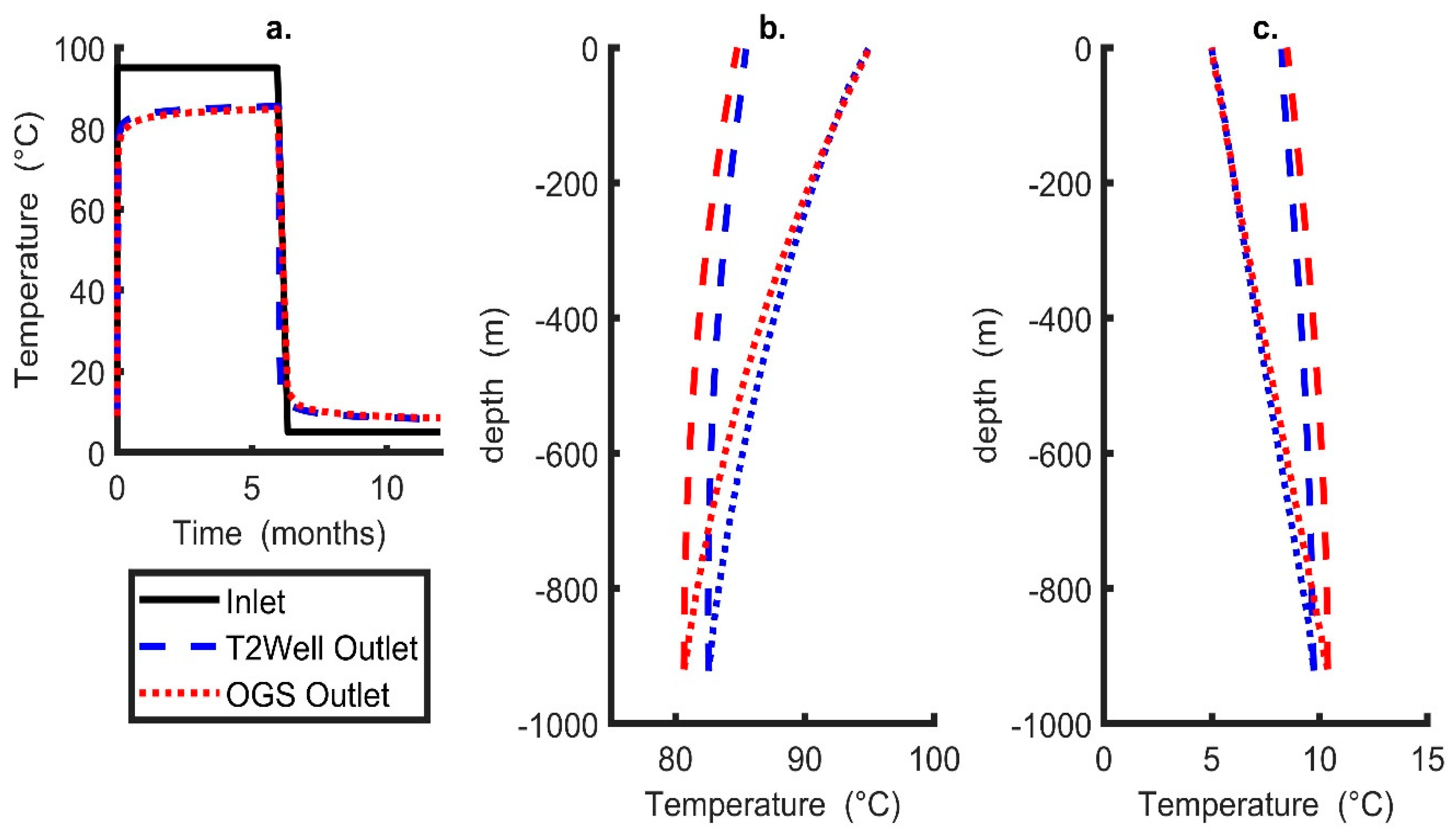
The (time variant) thermal power ( P ) at any given time during both charge and extraction can be calculated as (e.g., [50,51]):
P = ρ f c f Q ( T o u t T i n )
where Q is the volumetric flow rate (e.g., Table 1). The total thermal energy injected or extracted during a charge or discharge period can be calculated by integrating the power over the time of the charge or discharge cycle to obtain a value in TJ (1012 joules). The storage efficiency or recovery of heat is essential to understanding the performance of BTES. While different methods are used for calculating this value, in this study the method by Brown et al. [11] was used. Storage efficiency ( S E n e w ) was defined as the difference in energy extracted with and without charge with respect to the total energy injected:
S E n e w = T o t a l   e n e r g y   e x t r a c t e d   p o s t   c h a r g e T o t a l   e n e r g y   e x t r a c t e d   n o   c h a r g e T o t a l   e n e r g y   i n j e c t e d   d u r i n g   c h a r g e
Therefore, the increase in energy recovered after charge can be determined. For this study, the constant inlet temperature boundary condition was applied for modelling purposes, but in realistic operational conditions a constant thermal power would be used to reflect the surface supply of heat for charge and consumer demand for heat.

2.4. Benchmarking

OGS has been tested against a range of solutions generally providing little discrepancy; these include an analytical solution by Beier [52] (see [4,12,23]) and a numerical solution by Brown et al. [1] (see [10,11]), among many others. At present, data is unavailable for the NSCDGB site. Therefore, further benchmarking was undertaken in this study against a solution in T2Well-EOS1/TOUGH2 (see [53] for software description or [3] for DBHE setup). T2Well-EOS1/TOUGH2 is a wellbore-reservoir simulator that uses the integrated finite-volume method for the surrounding rocks and the drift flux method for solving fluid flow within the wellbore. It also models density, specific heat capacity and thermal conductivity of fluid in the wellbore as a function of pressure and temperature, which is in contrast to OGS. For T2Well-EOS1/TOUGH2, the pressure was assumed to increase with depth from 1 atm at the surface to a maximum pressure of 9 MPa at the base of the model. It also uses a 2D axis-symmetrical layout with the spatial domain set to 1423 and 1500 m (x, y). In this scenario, the parameters defined in Section 2.2 (Table 1) were used for comparison between the two software with no groundwater flow to test the DBHE model (i.e., conductive heat transfer in the surrounding rocks only). Other boundary and initial conditions were set up identical to those outlined in Section 2.2, other than for the base of the model where an infinite heat source term boundary was adopted.
It can be observed in Figure 4 that the models have a good fit with time (Figure 4a), with minimal variations in outlet temperature during extraction and charge. At the end of the charge period the difference in outlet temperature was ~0.6 °C and at the end of the extraction period it was ~0.2 °C. Similarly, there were minor differences in temperature corresponding to depth recorded at the end of the charge and extraction periods, respectively (Figure 4b,c). This could be due to either imposing an initial pressure boundary condition or the non-constant thermo-physical properties of the working fluid on T2Well-EOS1/TOUGH2, which will influence pressure and temperature with time within the DBHE.

3. Results

In this section the results of the numerical models are provided. Initially, the results without charge were discussed as they were required to evaluate the storage efficiency highlighted in Section 2.3 (Equation (10)). Then the impact of groundwater flow on varying thermal energy storage scenarios was evaluated. Four charge-discharge cycle types were investigated: (1) Continuous extraction only for a period of 6 months, (2) a baseline annual case of 6 months charge, followed by 6 months extraction, (3) an annual case of 1 month charge followed by 11 months extraction, (4) an annual simulation of 3 months charge followed by 9 months extraction and (5) an extended simulation of case 2 but for 5 years.

3.1. Extraction Only

Due to the method of calculating storage efficiency for BTES (i.e., Equation (10)), a period of “extraction only” must be evaluated for each case of thermal energy storage. As highlighted in Figure 5, the influence of groundwater has minimal impact on DBHEs when the Darcy velocity is less than or equal to 1e-7 m/s. When the Darcy velocity significantly exceeds this value (i.e., for 1e-6 m/s), it can be observed that there is a reduction in cooling of the borehole due to asymmetrical thermal drawdown and the cool thermal plume being transported away from the DBHE (Figure 5c,d). At values less than this, the advective transport of heat away from the DBHE by groundwater is minor. With a Darcy velocity of 1e-6 m/s, a thermal plume extends downstream from the DBHE, reaching ~40 m after 6 months, with a width of <10 m. In the absence of groundwater flow, the conductive radius of thermal influence extends to ~9 m from the borehole after 6 months.
At the end of the 6-month period of heat extraction, for the varying groundwater flows the minimum outlet temperature was 7.84 °C (no groundwater flow, conduction only) and the maximum was 9.04 °C (with 1e-6 m/s Darcy velocity). With no groundwater flow, the thermal power extracted was 66.4 kW (average over the 6 months) and 59.1 kW as recorded at the end of the 6 months. When groundwater Darcy velocity was 1e-6 m/s, the thermal power extracted was 85.8 kW (average) and 84.3 kW recorded at the end of the 6 months. This represents an increase of 25.2 kW in final thermal output. A variety of constant inlet temperatures (Figure 6) (from 5 °C to 10 °C, 15 °C and 20 °C) were investigated; it was found that outlet temperatures increase and thermal output decreases approximately linearly with increasing inlet temperature. The effect of flow rate within the borehole was analysed, and it was found that outlet temperature decreases and thermal power output increases (both non-linearly) with increasing flow rate (Figure 7). Increasing the Darcy velocity positively impacts both parameters by removing the coolth in proximity to the borehole, but the effect only becomes significant above 1e-7 m/s. The maximum increase in thermal power was observed for the highest circulation flow rate within the DBHE of 7 L/s, where thermal power recorded at the end of the 6 month simulation increased by 27.94 kW for the case with ( v f = 1e-6 m/s) relative to the case without groundwater flow (Figure 7b). Similarly, for the lowest inlet temperature during extraction (5 °C) the thermal power increased by 25.1 kW for with ( v f = 1e-6 m/s) and without groundwater flow.

3.2. Borehole Thermal Energy Storage

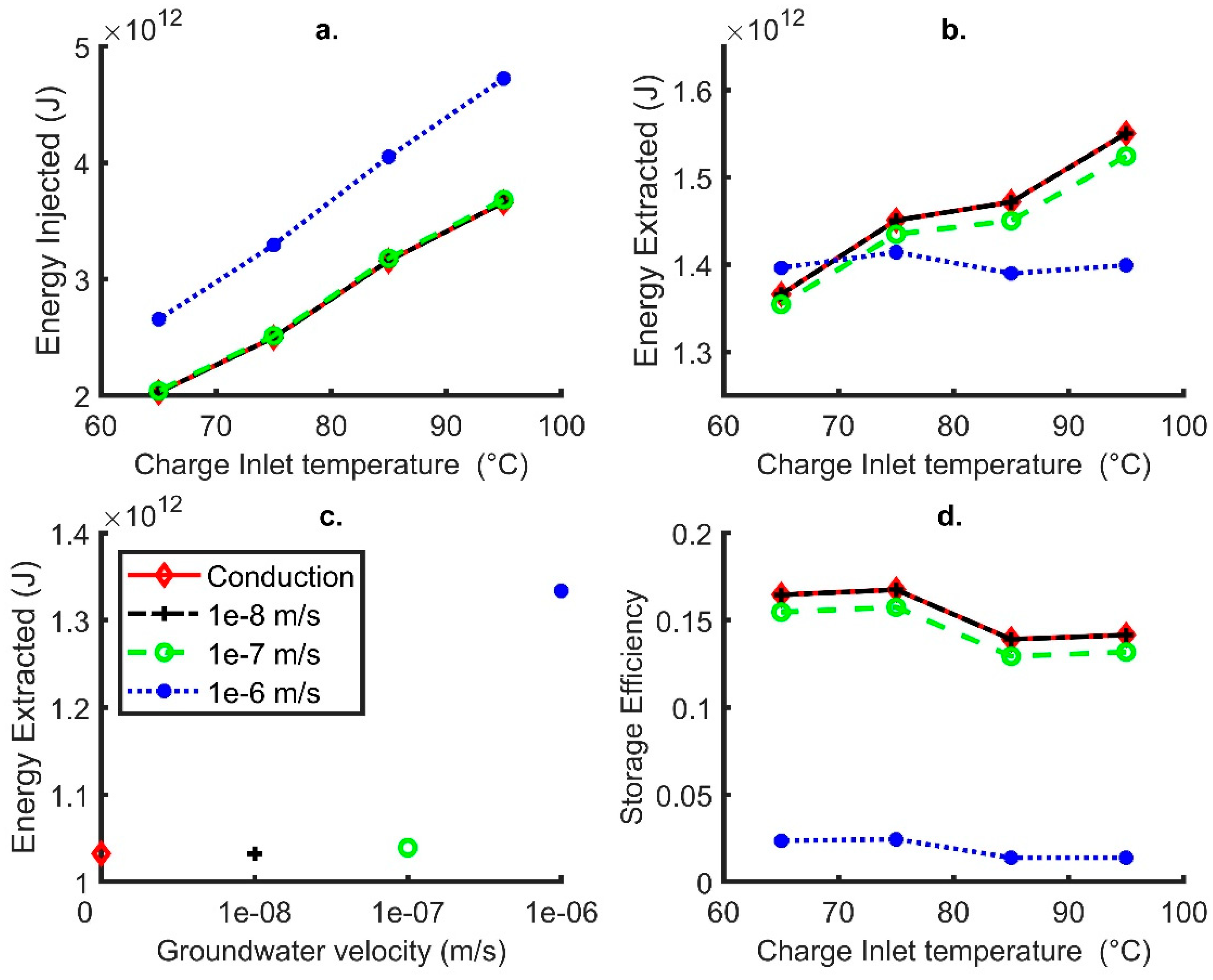
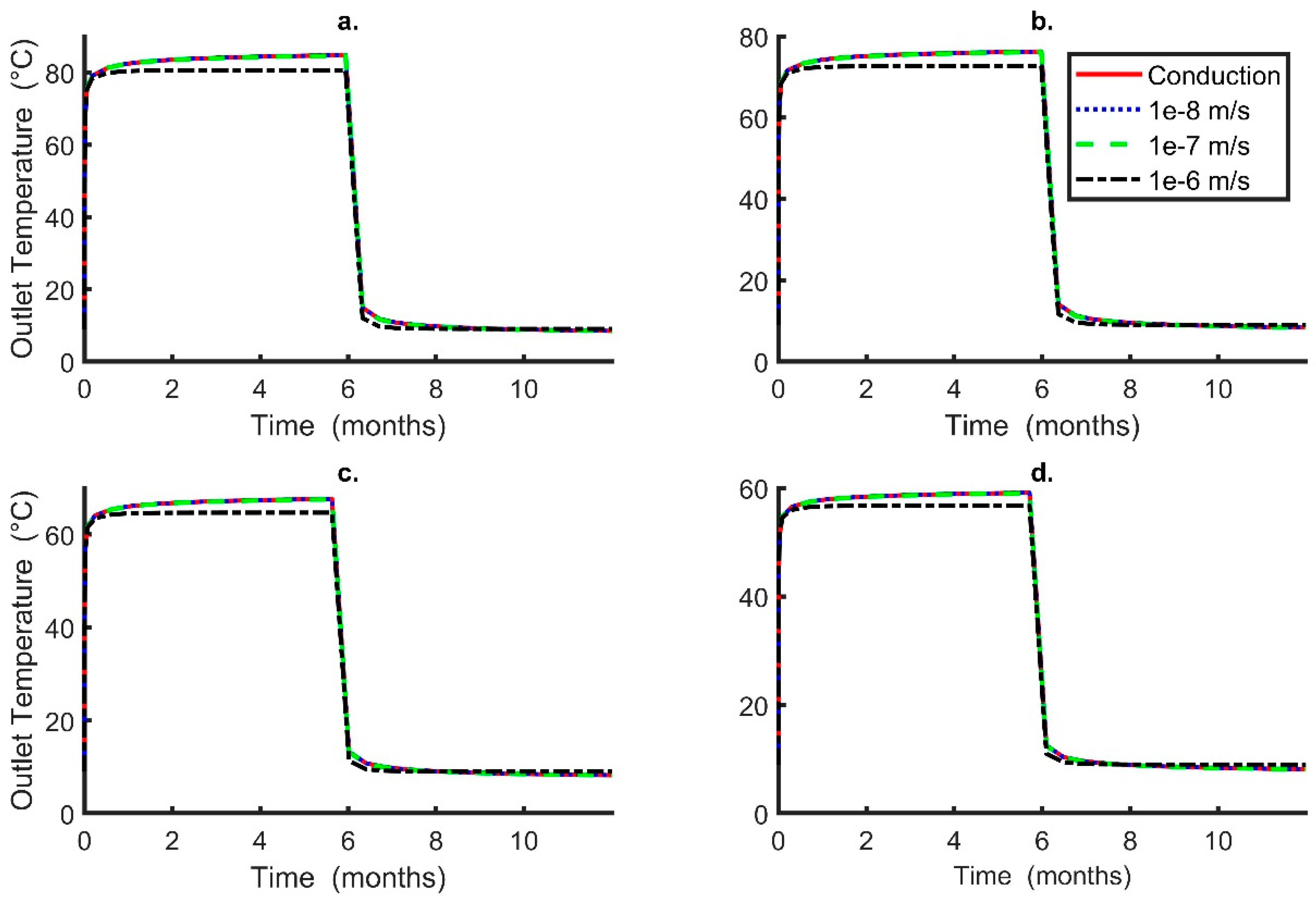
3.2.1. Influence of Inlet Temperature during Charge

The effects of DBHE inlet temperature during charge cycles was investigated for values between 65 and 95 °C as these might be typical inlet temperature for BTES systems around the world (e.g., [54]). An increase in charge inlet temperature corresponds to more thermal energy stored in the subsurface across all scenarios (Figure 8a). For lower Darcy velocities (1e-7 m/s or less), this corresponds to more energy recovered from the subsurface during the extraction period (Figure 8b). The increase in energy extracted as charge inlet temperature increases is relatively small when compared to the case without charge (Figure 8c); therefore, the storage efficiency reduces with greater charge inlet temperatures (Figure 8d).
When the Darcy velocity in the subsurface was set to 1e-6 m/s, far more energy was injected during charge for all temperatures as compared with lower Darcy velocities (Figure 8). This can be observed by the reduced outlet temperature during all charge periods (Figure 9); however, the outlet temperature during extraction was almost identical to the other lower velocity scenarios. This corresponds to minimal changes in the energy recovered after charge, regardless of the inlet temperature (Figure 8). The increase in energy stored was due to heat being transported away from the DBHE in a thermal plume by the movement of groundwater which was not recoverable. This aids in maintaining a larger difference in temperature between the DBHE and surrounding rock such that higher heat transfer occurs.
Inlet temperature during charge had a minor negative correlation to the storage efficiency and recovery of heat (Figure 8d). This was due to more heat stored in the formation which cannot be extracted efficiently, particularly with increased groundwater flow. The highest storage efficiency was recorded as 16% when there was no groundwater flow and charge inlet temperature was set at 65 °C, while the poorest storage efficiency was recorded at ~1% for the highest inlet temperatures (85 and 95 °C) and maximum Darcy velocity imposed.

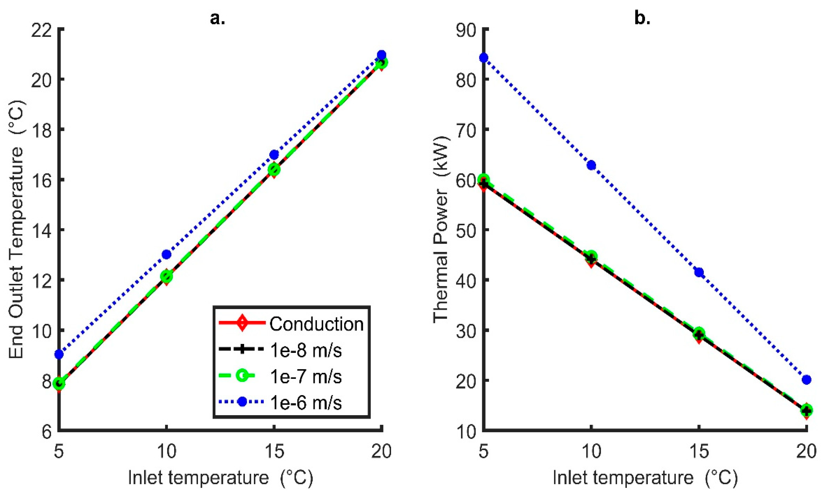
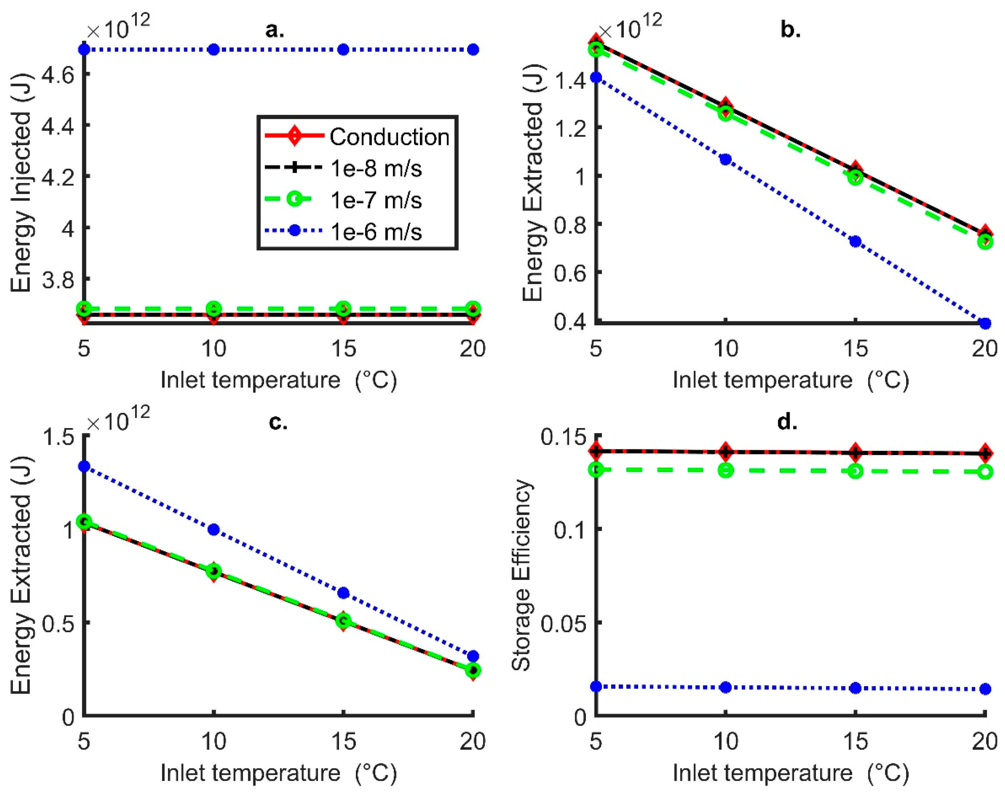
3.2.2. Influence of Inlet Temperature during Extraction

Inlet extraction temperatures of 5 to 20 °C were investigated, all of which are lower than the average undisturbed ground temperature along the length of the DBHE (i.e., 24.36 °C). If the value exceeds this average, then there is a risk that heat will tend to enter the geological environment, rather than being extracted from it. Furthermore, the lowest temperature was chosen to ensure no freezing within the DBHE (or potential heat pump) (e.g., [23]); however, if an antifreeze solution was used within the DBHE then lower temperatures could be used for the inlet. It was observed that the total energy recovered during extraction, with and without charge, significantly increases approximately linearly with declining inlet temperatures (Figure 10b,c). The impact of varying the extraction temperature on storage efficiency was negligible, as highlighted in Figure 10d. On the one hand, therefore, operating with a lower input temperature maximises energy extraction, but it has little effect on storage efficiency and lower inlet and outlet temperatures would, in turn, mean a lower operational efficiency for any heat pump being employed for heat delivery to a consumer.

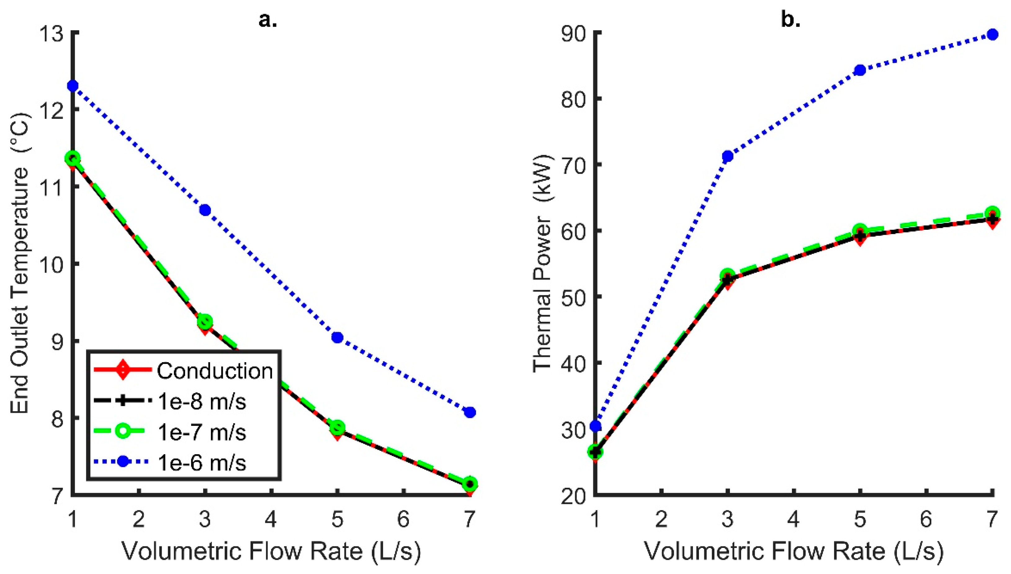
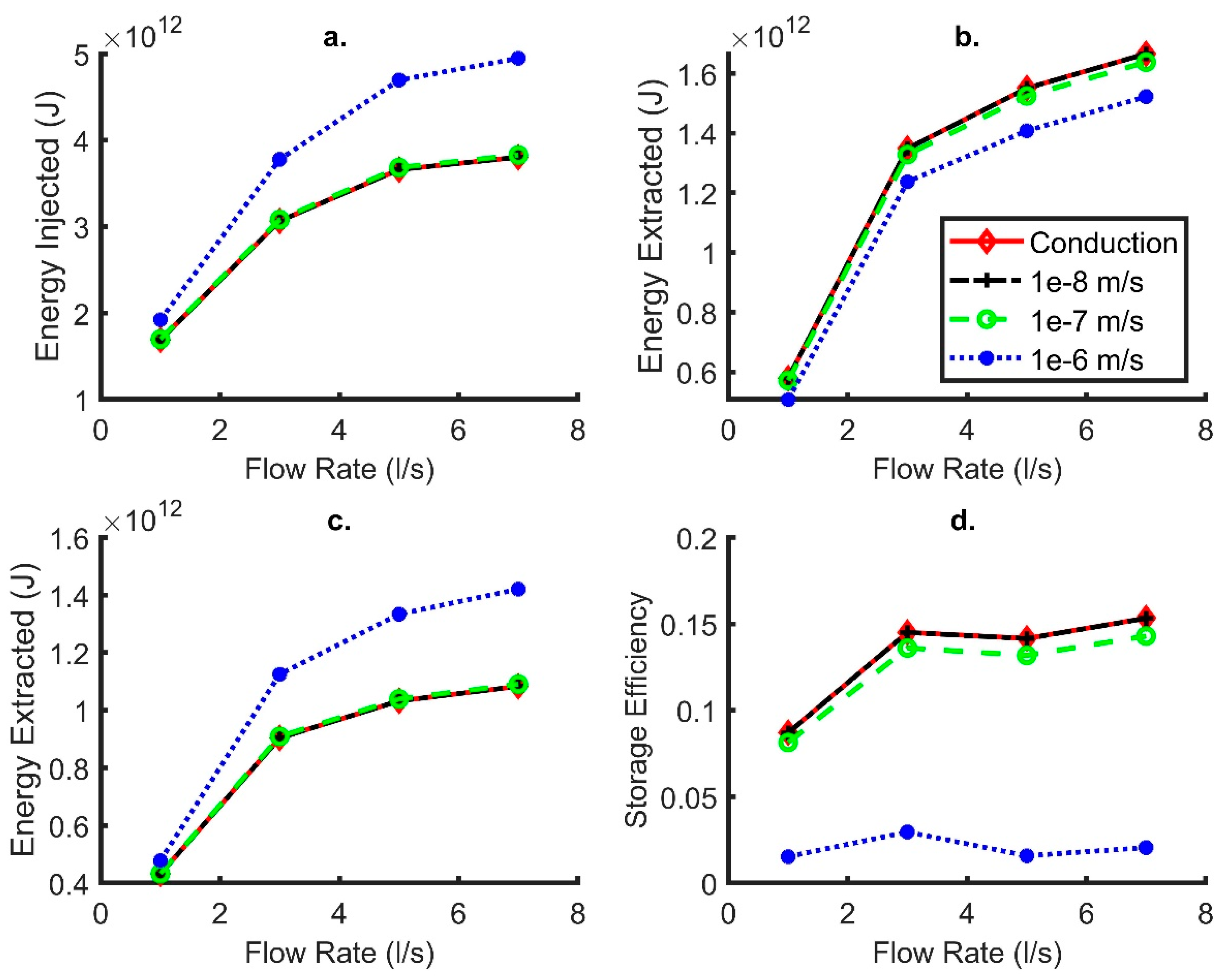
3.2.3. Influence of the Deep Borehole Heat Exchanger Internal Flow Rate

Flow rates for the water circulating internally within the co-axial DBHE of 1 to 7 L/s were investigated. With increasing flow rates, more energy was stored and extracted; this is because increasing fluid flow rate reduces the temperature difference between inlet and outlet, which in turn raises or lowers the average internal DBHE fluid temperature (during charge and extraction, respectively) and increases the temperature differential between the DBHE and the formation. Low groundwater velocities (<1e-8 m/s) result in minimal impact during extraction or charge. When the groundwater flow is 1e-7 m/,s there is a minor impact on the recovery of heat (Figure 11b), which consequently reduces the storage efficiency across all flow rates. For flow rates of 1 L/s in the wellbore the storage efficiency was reduced in comparison to the no groundwater flow simulation by 0.5%, whilst for 7 L/s it 1% lower.
When the Darcy velocity was set at 1e-6 m/s, flow rate had minimal impact on the recovery of heat (Figure 8b) in contrast to heat extraction without storage (Figure 8c). Furthermore, storage was very inefficient for higher Darcy velocities and most of the energy injected was transported away from the DBHE and the recovery of heat was always less than 3% for different fluid flow rates in the wellbore.

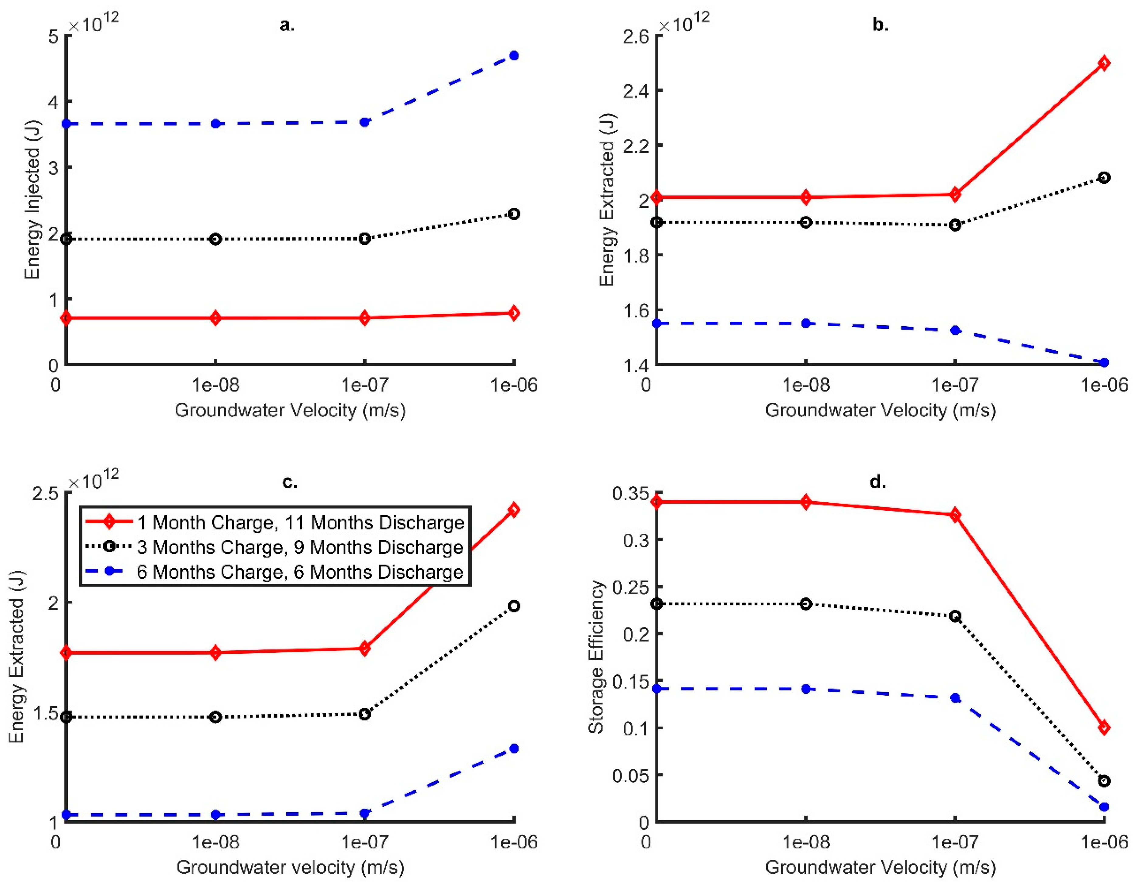
3.2.4. Influence of Varying Charge Periods

The charge period was reduced to (1) 3 months, followed by a discharge period of 9 months, and (2) 1 month, followed by a discharge period of 11 months. This enabled the testing of different charge periods to evaluate if the storage efficiency improves with varying modes of operation. With shorter charge periods there is less time for heat to propagate away, increasing the storage efficiency across all groundwater velocities (Figure 12). When the groundwater velocity was less than or equal to 1e-7 m/s the storage efficiency was always greater than 21 and 32% for the 3 months and 1 month charge periods, respectively (Figure 12d). Maximum storage efficiencies were recorded for the conductive heat flux only scenario with storage efficiencies reaching 23 and 34%, respectively, for 3- and 1-month charge periods.
This suggests that DBHEs are most effectively used for underground thermal energy storage, when used with short periods of intense (high power) heat charge, followed by longer periods of discharge. This is because, during the short charge period, heat does not have time to disseminate far from the DBHE, before discharge commences, the radial thermal gradient is reversed and the heat is induced back towards the DBHE.

3.2.5. Long Term Simulations

The simulation has been extended to cover a 5-year period, comprising annual charge and discharge cycles each of 6 months duration. Inlet temperatures during charge have been constant at 95 °C and during discharge at 5 °C, while the internal DBHE fluid flow rate was 5 L/s. In this study, the recovery of heat improves slightly with time, with outlet temperature increasing from the end of the first to last (year 5) charge periods from 8.4 to 8.8 °C for the no groundwater flow case (Figure 13). This is simply because, for each year, more heat is injected (~3.6 TJ per cycle) than is extracted (~1.6 TJ per cycle), so the ground has an inevitable tendency to warm. For the highest groundwater Darcy velocity of 1e-6 m/s, the outlet temperature at the end of the extraction period remains constant with time at 9.04 °C. This emphasises the observation that the importance of groundwater flow for enhancing heat extraction from a DBHE (irrespective of any charge cycle) is more than any thermal storage effect (which declines with increasing ground water flow). For the highest groundwater Darcy flow of 1e-6 m/s, the length of the corresponding thermal plume increases with time, in excess of 250 m after 5 years as the plume reaches the outer boundaries of the model (i.e., in comparison for the first cycle v last in Figure 14).

4. Discussion

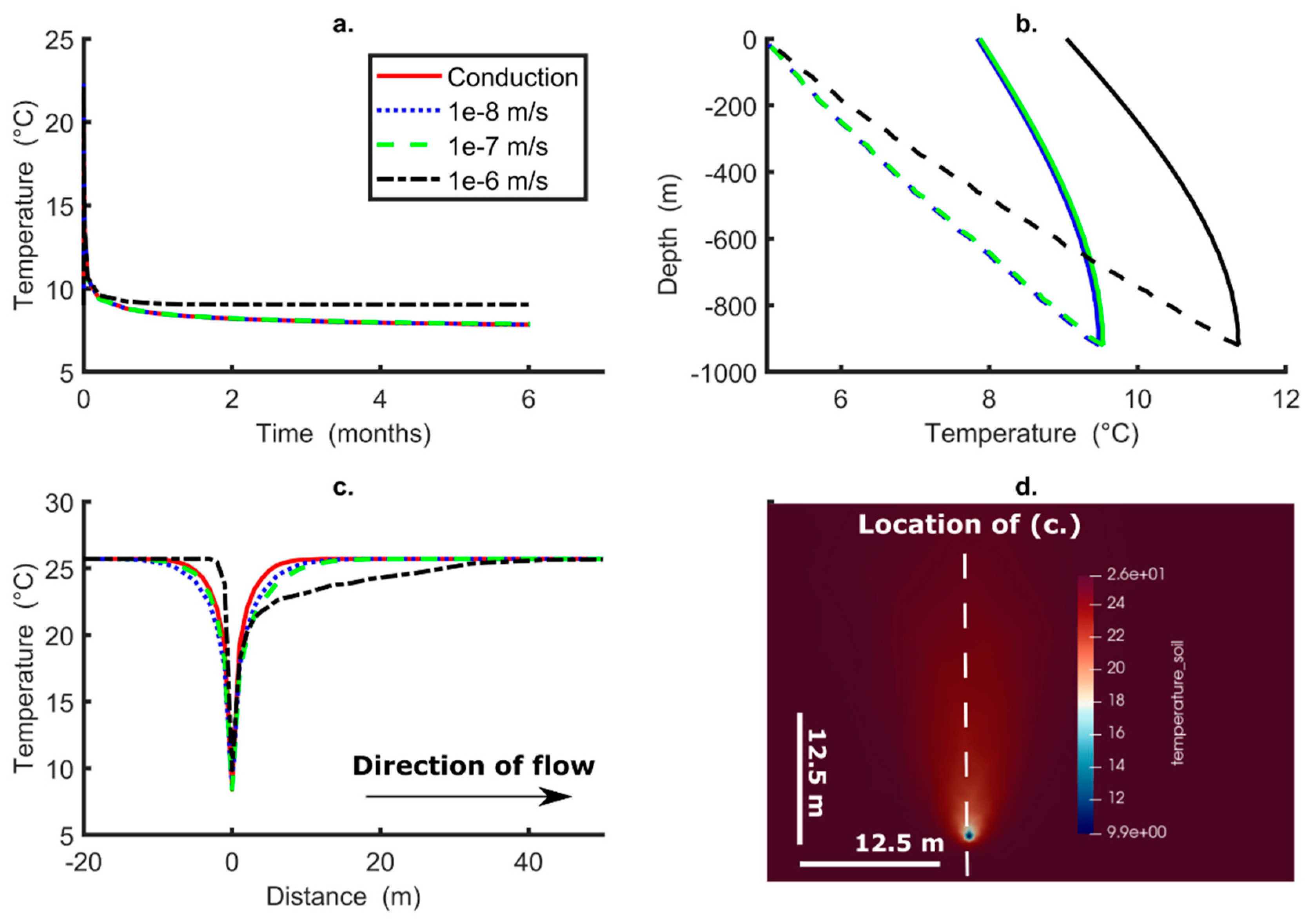
4.1. Implications of an Active Groundwater Flow on Heat Extraction Only

Groundwater flow has a positive impact when extracting heat from DBHEs, compared to cases where there is no advective transport of heat in the ground. The advective transport of heat through the DBHE (equivalent to the advective transport of “coolth” away from it) only becomes significant when the groundwater Darcy velocity exceeds 1e-7 m/s (Figure 5c). Such a Darcy velocity is only achieved when hydraulic conductivity exceeds 1e-5 m/s (or 0.9 m/d) for a hydraulic gradient of 0.01. Such hydraulic conductivities and gradients are the exception rather than the rule, and unlikely in most systems (including the NSCDGB), at depths of 1–2 km, explaining Chen et al.’s [23] conclusion that groundwater only has a minor impact on DBHEs. However, this study concludes that, in cases where DBHEs penetrate thick aquifers with a Darcy velocity in the region of 1e-6 m/s or greater, available thermal outputs will be positively impacted by groundwater flow.

4.2. Implications of an Active Groundwater Flow on Borehole Thermal Energy Storage

In contrast to single DBHEs that operate to extract heat only, the storage of thermal energy in DBHEs is negatively impacted by groundwater flow. Groundwater flows with a Darcy velocity of 1e-6 m/s reduce the thermal energy storage efficiency to less than 5% across all simulations for a period of 6 months injection and 6 months extraction. Previous work has suggested that deep BTES in a single borehole is less efficient than more equidimensional (and shallower) BTES arrays, but nevertheless could be useful if there is an otherwise unusable surplus of heat in proximity to an abandoned well that could be repurposed [11]. This study is in agreement that the recovery of heat after storage is limited due to the poor efficiencies. Any potential for storage could be limited even further if groundwater is present. It does, however, appear the optimal form of underground thermal energy storage in DBHEs is with short term, high-power charges of thermal energy, followed by longer periods of heat extraction. Cycles of 1 month charge, followed by 11 months extraction appear to result in storage efficiencies in excess of 30%. Therefore, there could be potential to combine this technology with curtailed wind or waste heat discharged in shorter time periods, rather than for seasonal thermal energy storage. Future work should investigate the influence of groundwater flow in shallow aquifers or fractures within the ground which are more likely to be encountered than the significant thicknesses of aquifer modelled in this study.

4.3. Implications to Prospective Areas within the UK

In the UK, and internationally, there are a series of deep sedimentary basins with thick successions of sandstone aquifers. These are usually targets for both hydrocarbon and geothermal developments and they can encounter deep groundwater (e.g., [16,17]). Within England, the four major Mesozoic basins include the Wessex, Cheshire, East England, and Worcester; their infill is dominated by Permo-Triassic aquifers that can be up to 2 km in thickness (e.g., Knutsford-1 well in the Cheshire Basin—see [26]). Therefore, if looking to develop or repurpose a DBHE then local groundwater conditions must be considered. For context, the regional Darcy velocity value of 1e-7 m/s can be related to sandstone aquifers with a hydraulic conductivity of ~1e-5 m/s and hydraulic gradient of 1% [36]. The geometric mean of core data from Permo-Triassic rocks in the UK is within this magnitude (albeit from shallower boreholes) [55] and DBHEs could be impacted by deeper flows.

4.4. Comparison with Previous Studies for Shallow BTES

Modelling results indicated regional groundwater flow impacts a deep single BHE BTES system when Darcy velocity approaches 1e-6 m/s. This is similar to that modelled in the literature for shallow BTES arrays which typically indicate that a Darcy velocity less than c. 1e-7 m/s has little impact on borehole heat exchanger performance [35,36,56,57,58,59,60]. Therefore, the influence of groundwater is not dependent on the depth of the BTES system in the subsurface.

5. Conclusions

In this study, the influence of groundwater flows on DBHEs for both heat extraction and BTES was considered. While groundwater flows positively improve the amount of heat that can be extracted it limits the possibility of deep single well BTES. A model on OGS was constructed to test the local advective heat transport associated groundwater movement on the operation of a DBHE. Initial, preliminary testing in comparison to T2Well-EOS1/TOUGH2 subsurface showed the model to have limited discrepancy (outlet temperature within 0.6 °C), giving confidence in the results of this study. A series of simulations to test the impact of the most influential parameters on BTES (as determined by [11]) and groundwater flow were then tested for heat extraction for 6 months and thermal energy storage for 1 year periods. The influence of the charge time period was also considered, before testing cyclic operation for a number of years. The key conclusions were:
  • Groundwater flow from thick aquifers with a Darcy velocity around or greater than 1e-6 m/s has a positive impact on heat extraction using DBHEs and will likely increase the longevity of such systems. The impact of this reduces with increased extraction inlet temperature whilst it significantly improves the achievable thermal power with increased flow rates.
  • In contrast, increasing groundwater flow (approaching or above 1e-6 m/s) for BTES in single well DBHEs negatively impacts the storage efficiency (<5%).
  • Increasing the internal DBHE fluid flow rate in lower Darcy velocity conditions did improve the performance for BTES by over 5%.
  • Reducing the charge period significantly increases the recovery of heat, with charge periods of 1 and 3 months (followed by 11 months and 9 months discharge) resulting in storage efficiencies of up to 34 and 23%, respectively. Therefore, it may be more beneficial for DBHEs used for thermal energy storage to apply short, intense charge periods, followed by longer discharge periods.
  • Simulation over a longer (5 year) series of charge-discharge cycles only has a minor impact on the recovery of heat, at least in the “fixed inlet temperature” mode of simulation that has been adopted in this paper.
  • To maximize the storage efficiencies in single well BTES systems, specific to the modelled parameters in this paper at 920 m depth, it appears that it is best to have lower charge temperatures (of 65 °C), higher circulation flow rates (of 7 L/s), lower charge periods (of 1 month of less) and target subsurface systems with aquifer Darcy velocity of 1e-7 m/s or less.

Author Contributions

Conceptualization, C.S.B.; methodology, C.S.B., H.D. and I.K.; software, C.S.B., H.D. and I.K.; validation, C.S.B. and H.D.; formal analysis, C.S.B.; investigation, C.S.B.; writing—original draft preparation, C.S.B. and H.D.; writing—review and editing, C.S.B., H.D., I.K., D.B. and G.F.; visualization, C.S.B.; supervision, D.B. and G.F.; funding acquisition, G.F. All authors have read and agreed to the published version of the manuscript.

Funding

We would like to show appreciation to the UKRI EPSRC (grant reference numbers EPSRC EP/T022825/1 and EPSRC EP/T023112/1) for funding this research. The funding sources are for the NetZero GeoRDIE (Net Zero Geothermal Research for District Infrastructure Engineering) and INTEGRATE (Integrating seasoNal Thermal storagE with multiple enerGy souRces to decArobonise Thermal Energy) projects, respectively. For the purpose of open access, the author has applied a Creative Commons Attribution (CC BY) licence to any Author Accepted Manuscript version arising from this submission.

Data Availability Statement

Data will be made available on request.

Acknowledgments

The authors would like to thank three anonymous reviewers for their supportive and constructive reviews.

Conflicts of Interest

The authors declare no conflict of interest.

References

  1. Brown, C.S.; Cassidy, N.J.; Egan, S.S.; Griffiths, D. Numerical modelling of deep coaxial borehole heat exchangers in the Cheshire Basin, UK. Comput. Geosci. 2021, 152, 104752. [Google Scholar] [CrossRef]
  2. Falcone, G.; Liu, X.; Okech, R.R.; Seyidov, F.; Teodoriu, C. Assessment of deep geothermal energy exploitation methods: The need for novel single-well solutions. Energy 2018, 160, 54–63. [Google Scholar] [CrossRef] [Green Version]
  3. Doran, H.R.; Renaud, T.; Falcone, G.; Pan, L.; Verdin, P.G. Modelling an unconventional closed-loop deep borehole heat exchanger (DBHE): Sensitivity analysis on the Newberry volcanic setting. Geotherm. Energy 2021, 9, 4. [Google Scholar] [CrossRef]
  4. Cai, W.; Wang, F.; Jiang, J.; Wang, Z.; Liu, J.; Chen, C. Long-term performance evaluation and economic analysis for deep borehole heat exchanger heating system in Weihe basin. Front. Earth Sci. 2022, 10, 806416. [Google Scholar] [CrossRef]
  5. Gascuel, V.; Raymond, J.; Rivard, C.; Marcil, J.S.; Comeau, F.A. Design and optimization of deep coaxial borehole heat exchangers for cold sedimentary basins. Geothermics 2022, 105, 102504. [Google Scholar] [CrossRef]
  6. Kolo, I.; Brown, C.S.; Falcone, G. Thermal Power from a Notional 6 km Deep Borehole Heat Exchanger in Glasgow. In Proceedings of the 48th Workshop on Geothermal Reservoir Engineering, Stanford, CA, USA, 6–8 February 2023. [Google Scholar]
  7. Alimonti, C.; Soldo, E. Study of geothermal power generation from a very deep oil well with a wellbore heat exchanger. Renew. Energy 2016, 86, 292–301. [Google Scholar] [CrossRef]
  8. Nian, Y.L.; Cheng, W.L.; Yang, X.Y.; Xie, K. Simulation of a novel deep ground source heat pump system using abandoned oil wells with coaxial BHE. Int. J. Heat Mass Transf. 2019, 137, 400–412. [Google Scholar] [CrossRef]
  9. Hu, X.; Banks, J.; Wu, L.; Liu, W.V. Numerical modeling of a coaxial borehole heat exchanger to exploit geothermal energy from abandoned petroleum wells in Hinton, Alberta. Renew. Energy 2020, 148, 1110–1123. [Google Scholar] [CrossRef]
  10. Kolo, I.; Brown, C.S.; Falcone, G.; Banks, D. Closed-loop Deep Borehole Heat Exchanger: Newcastle Science Central Deep Geothermal Borehole. In Proceedings of the European Geothermal Congress, Berlin, Germany, 17–21 October 2022. [Google Scholar]
  11. Brown, C.S.; Kolo, I.; Falcone, G.; Banks, D. Repurposing a Deep Geothermal Exploration Well for Borehole Thermal Energy Storage: Implications from Statistical Modelling and Sensitivity Analysis. Appl. Therm. Eng. 2023, 220, 119701. [Google Scholar] [CrossRef]
  12. Brown, C.S.; Kolo, I.; Falcone, G.; Banks, D. Investigating scalability of deep borehole heat exchangers: Numerical modelling of arrays with varied modes of operation. Renew. Energy 2023, 202, 442–452. [Google Scholar] [CrossRef]
  13. Kolo, I.; Brown, C.S.; Falcone, G.; Banks, D. Repurposing a Geothermal Exploration Well as a Deep Borehole Heat Exchanger: Understanding Long-Term Effects of Lithological Layering, Flow Direction, and Circulation Flow Rate. Sustainability 2023, 15, 4140. [Google Scholar] [CrossRef]
  14. Skarphagen, H.; Banks, D.; Frengstad, B.S.; Gether, H. Design considerations for borehole thermal energy storage (BTES): A review with emphasis on convective heat transfer. Geofluids 2019, 2019, 4961781. [Google Scholar] [CrossRef]
  15. Welsch, B.; Ruehaak, W.; Schulte, D.O.; Baer, K.; Sass, I. Characteristics of medium deep borehole thermal energy storage. Int. J. Energy Res. 2016, 40, 1855–1868. [Google Scholar] [CrossRef]
  16. Medici, G.; West, L.; Mountney, N.P.; Welch, M. Permeability of rock discontinuities and faults in the Triassic Sherwood Sandstone Group (UK): Insights for management of fluvio-aeolian aquifers worldwide. Hydrogeol. J. 2019, 27, 2835–2855. [Google Scholar] [CrossRef] [Green Version]
  17. Brown, C.S.; Cassidy, N.J.; Egan, S.S.; Griffiths, D. A sensitivity analysis of a single extraction well from deep geothermal aquifers in the Cheshire Basin, UK. Q. J. Eng. Geol. Hydrogeol. 2022, 55. [Google Scholar] [CrossRef]
  18. Xie, K.; Nian, Y.L.; Cheng, W.L. Analysis and optimization of underground thermal energy storage using depleted oil wells. Energy 2018, 163, 1006–1016. [Google Scholar] [CrossRef]
  19. Younger, P.L.; Manning, D.A.; Millward, D.; Busby, J.P.; Jones, C.R.; Gluyas, J.G. Geothermal exploration in the Fell Sandstone Formation (Mississippian) beneath the city centre of Newcastle upon Tyne, UK: The Newcastle Science Central deep geothermal borehole. Q. J. Eng. Geol. Hydrogeol. 2016, 49, 350–363. [Google Scholar] [CrossRef] [Green Version]
  20. Howell, L.; Brown, C.S.; Egan, S.S. Deep geothermal energy in northern England: Insights from 3D finite difference temperature modelling. Comput. Geosci. 2021, 147, 104661. [Google Scholar] [CrossRef]
  21. Brown, C.S. Regional geothermal resource assessment of hot dry rocks in Northern England using 3D geological and thermal models. Geothermics 2022, 105, 102503. [Google Scholar] [CrossRef]
  22. Shao, H.; Hein, P.; Sachse, A.; Kolditz, O. Geoenergy Modeling II: Shallow Geothermal Systems; Springer International Publishing: Berlin/Heidelberg, Germany, 2016. [Google Scholar]
  23. Chen, C.; Shao, H.; Naumov, D.; Kong, Y.; Tu, K.; Kolditz, O. Numerical investigation on the performance, sustainability, and efficiency of the deep borehole heat exchanger system for building heating. Geotherm. Energy 2019, 7, 18. [Google Scholar] [CrossRef] [Green Version]
  24. Cai, W.; Wang, F.; Chen, S.; Chen, C.; Liu, J.; Deng, J.; Kolditz, O.; Shao, H. Analysis of heat extraction performance and long-term sustainability for multiple deep borehole heat exchanger array: A project-based study. Appl. Energy 2021, 289, 116590. [Google Scholar] [CrossRef]
  25. Chen, S.; Cai, W.; Witte, F.; Wang, X.; Wang, F.; Kolditz, O.; Shao, H. Long-term thermal imbalance in large borehole heat exchangers array–A numerical study based on the Leicester project. Energy Build. 2021, 231, 110518. [Google Scholar] [CrossRef]
  26. Wight, A. Knutsford NO.1. Well Completion Report. 631. 1974. Available online: http://scans.bgs.ac.uk/sobi_scans/boreholes/749082/images/12269805.html (accessed on 27 October 2022).
  27. Downing, R.A.; Gray, D.A. (Eds.) Geothermal Energy–The Potential in the 495 United Kingdom; HMSO: London, UK, 1986. [Google Scholar]
  28. Rollin, K.E.; Kirby, G.A.; Rowley, W.J.; Buckley, D.K. Atlas of Geothermal Resources in Europe: UK Revision; Technical Report WK/95/07; British Geological Survey: Keyworth, UK, 1995.
  29. Jackson, T. Geothermal Potential in Great Britain and Northern Ireland; Sinclair Knight Merz: Sydney, NSW, Australia, 2012. [Google Scholar]
  30. Busby, J. Geothermal energy in sedimentary basins in the UK. Hydrogeol. J. 2014, 22, 129–141. [Google Scholar] [CrossRef] [Green Version]
  31. Brown, C.S. Revisiting the Deep Geothermal Potential of the Cheshire Basin, UK. Energies 2023, 16, 1410. [Google Scholar] [CrossRef]
  32. Watson, S.M.; Falcone, G.; Westaway, R. Repurposing hydrocarbon wells for geothermal use in the UK: The onshore fields with the greatest potential. Energies 2020, 13, 3541. [Google Scholar] [CrossRef]
  33. Watson, S.M.; Falcone, G.; Westaway, R. Repurposing hydrocarbon wells for geothermal use in the UK: A preliminary resource assessment. In Proceedings of the World Geothermal Conference, Reykjavik, Iceland, 24–27 October 2021. [Google Scholar]
  34. Medici, G.; West, L.J. Review of groundwater flow and contaminant transport modelling approaches for the Sherwood Sandstone aquifer, UK; insights from analogous successions worldwide. Q. J. Eng. Geol. Hydrogeol. 2022, 55, qjegh2021-176. [Google Scholar] [CrossRef]
  35. Emad Dehkordi, S.; Schincariol, R.A.; Olofsson, B. Impact of groundwater flow and energy load on multiple borehole heat exchangers. Groundwater 2015, 53, 558–571. [Google Scholar] [CrossRef] [Green Version]
  36. Nguyen, A.; Pasquier, P.; Marcotte, D. Borehole thermal energy storage systems under the influence of groundwater flow and time-varying surface temperature. Geothermics 2017, 66, 110–118. [Google Scholar] [CrossRef]
  37. Al-Khoury, R.; Kölbel, T.; Schramedei, R. Efficient numerical modeling of borehole heat exchangers. Comput. Geosci. 2010, 36, 1301–1315. [Google Scholar] [CrossRef]
  38. Diersch, H.J.; Bauer, D.; Heidemann, W.; Rühaak, W.; Schätzl, P. Finite element modeling of borehole heat exchanger systems: Part 1. Fundamentals. Comput. Geosci. 2011, 37, 1122–1135. [Google Scholar] [CrossRef]
  39. Busby, J.; Terrington, R. Assessment of the resource base for engineered geothermal systems in Great Britain. Geotherm. Energy 2017, 5, 7. [Google Scholar] [CrossRef]
  40. Gluyas, J.G.; Adams, C.A.; Busby, J.P.; Craig, J.; Hirst, C.; Manning, D.A.C.; McCay, A.; Narayan, N.S.; Robinson, H.L.; Watson, S.M.; et al. Keeping warm: A review of deep geothermal potential of the UK. Proc. Inst. Mech. Eng. Part A J. Power Energy 2018, 232, 115–126. [Google Scholar] [CrossRef] [Green Version]
  41. Siena, M.; Hyman, J.D.; Riva, M.; Guadagnini, A.; Winter, C.L.; Smolarkiewicz, P.K.; Gouze, P.; Sadhukhan, S.; Inzoli, F.; Guédon, G.; et al. Direct numerical simulation of fully saturated flow in natural porous media at the pore scale: A comparison of three computational systems. Comput. Geosci. 2015, 19, 423–437. [Google Scholar] [CrossRef]
  42. Westaway, R. Rock thermal properties for Newcastle Helix site. In Internal University of Glasgow report for NetZero GeoRDIE Project; University of Glasgow: Glasgow, UK, 2020; unpublished. [Google Scholar]
  43. Banks, D. Thermal properties of well construction materials—Newcastle Science Central borehole. In Internal University of Glasgow Report for NetZero GeoRDIE Project; University of Glasgow: Glasgow, UK, 2021; unpublished. [Google Scholar]
  44. Kimbell, G.S.; Carruthers, R.M.; Walker, A.S.D.; Williamson, J.P. Regional geophysics of southern Scotland and northern England. Version 1.0 on CD-ROM. British Geological Survey, Keyworth. 2006. Available online: https://shop.bgs.ac.uk/Bookshop/product.cfm?p_id=KRGSCD (accessed on 20 October 2020).
  45. Gebski, J.S.; Wheildon, J.; Thomas-Betts, A. Investigations of the UK Heat Flow Field (1984–1987); Report WJ/GE/87/6; British Geological Survey: Nottingham, UK, 1987; Volume 60.
  46. Bott, M.H.P.; Johnson, G.A.L.; Mansfield, J.; Wheilden, J. Terrestrial heat flow in north-east England. Geophys. J. R. Astron. Soc. 1972, 27, 277–288. [Google Scholar] [CrossRef] [Green Version]
  47. England, P.C.; Oxburgh, E.R.; Richardson, S.W. Heat refraction and heat production in and around granite plutons in north–east England. Geophys. J. Int. 1980, 62, 439–455. [Google Scholar] [CrossRef] [Green Version]
  48. Westaway, R.; Younger, P.L. Unravelling the relative contributions of climate change and ground disturbance to subsurface temperature perturbations: Case studies from Tyneside, UK. Geothermics 2016, 64, 490–515. [Google Scholar] [CrossRef] [Green Version]
  49. Lesniak, B.; Słupik, Ł.; Jakubina, G. The determination of the specific heat capacity of coal based on literature data. Chemik 2013, 67, 560–571. [Google Scholar]
  50. Dijkshoorn, L.; Speer, S.; Pechnig, R. Measurements and design calculations for a deep coaxial borehole heat exchanger in Aachen, Germany. Int. J. Geophys. 2013, 2013, 916541. [Google Scholar] [CrossRef] [Green Version]
  51. Liu, J.; Wang, F.; Cai, W.; Wang, Z.; Wei, Q.; Deng, J. Numerical study on the effects of design parameters on the heat transfer performance of coaxial deep borehole heat exchanger. Int. J. Energy Res. 2019, 43, 6337–6352. [Google Scholar] [CrossRef]
  52. Beier, R.A. Thermal response tests on deep borehole heat exchangers with geothermal gradient. Appl. Therm. Eng. 2020, 178, 115447. [Google Scholar] [CrossRef]
  53. Pan, L.; Oldenburg, C.M. T2Well—An integrated wellbore–reservoir simulator. Comput. Geosci. 2014, 65, 46–55. [Google Scholar] [CrossRef]
  54. Kallesøe, A.J.; Vangkilde-Pedersen, T.; Guglielmetti, L. HEATSTORE Underground Thermal Energy Storage (UTES)–State-of-the-Art, Example Cases and Lessons Learned. 2019. Available online: https://archive-ouverte.unige.ch/unige:157363 (accessed on 1 March 2023).
  55. Allen, D.J.; Brewerton, L.J.; Coleby, L.M.; Gibbs, B.R.; Lewis, M.A.; MacDonald, A.M.; Wagstaff, S.J.; Williams, A.T. The Physical Properties of Major Aquifers in England and Wales; British Geological Survey: Nottingham, UK, 1997.
  56. Ingersoll, L.R.; Zabel, O.J.; Ingersoll, A.C. Heat conduction with engineering, geological, and other applications. Phys. Today 1955, 8, 17. [Google Scholar] [CrossRef]
  57. Van Meurs, G. Seasonal Heat Storage in the Soil. Ph.D. Thesis, University of Technology Delft, Delft, The Netherlands, 1985. [Google Scholar]
  58. Nordell, B. Borehole heat store design optimization. Ph.D. Thesis, Luleå Tekniska Universitet, Luleå, Sweden, 1994. [Google Scholar]
  59. Banks, D. A review of the importance of regional groundwater advection for ground heat exchange. Environ. Earth Sci. 2015, 73, 2555–2565. [Google Scholar] [CrossRef]
  60. Brown, C.S.; Desguers, T.; Lyden, A.; Kolo, I.; Friedrich, D.; Falcone, G. Modelling Borehole Thermal Energy Storage using Curtailed Wind Energy as a Fluctuating Source of Charge. In Proceedings of the 48th Workshop on Geothermal Reservoir Engineering, Stanford, CA, USA, 6–8 February 2023. [Google Scholar]
Figure 1. DBHE schematic with cold plume created during extraction (modified from [1]).
Energies 16 02677 g001
Figure 2. Map of the UK and approximate location of the study area (from [11]).
Energies 16 02677 g002
Figure 3. Example fully discretised mesh and domain size.
Energies 16 02677 g003
Figure 4. Comparison between OpenGeoSys (OGS) and T2Well-EOS1/TOUGH2 for the initial charge scenario. (a) Inlet and outlet temperatures for the different software, (b) comparison of the vertical profile with depth at the end of charge and (c) comparison of the vertical profile at the end of the extraction period. Note that the dashed line in (b,c) is the central pipe, whilst the dotted line is for the annular space. For the first 6 months of charge a constant inlet temperature of 95 °C was applied and for the subsequent 6 months of discharge an inlet temperature of 5 °C was used.
Energies 16 02677 g004
Figure 5. Varying groundwater flows plotted for extraction operation only for 6 months. (a) is the evolution of outlet temperature with time (note inlet is set equal to 5 °C), (b) is the change in the temperature within the central pipe (solid line) and annulus (dashed line) at the end of the simulation (note that when groundwater flow is set to zero the red line is directly underneath that for the velocity set at 1e-8 m/s), (c) is the thermal propagation around the BHE at 500 m depth (BHE is at point zero) and (d) is the thermal plume at 500 m depth for a flow velocity of 1e-6 m/s.
Energies 16 02677 g005
Figure 6. Six-month simulation of heat extraction only from DBHE, with constant inlet temperature and internal fluid flow rate of 5 L/s. (a) shows the impact of varying DBHE constant inlet temperature and groundwater Darcy velocity on DBHE outlet temperature; (b) shows the impact on final thermal output from DBHE after 6 months. Groundwater Darcy velocity is varied between 0 m/s (conduction only) and 1e-6 m/s. Outlet temperatures and thermal powers were recorded at the end of the simulation.
Energies 16 02677 g006
Figure 7. Six-month simulation of heat extraction only from DBHE, with constant inlet temperature of 5 °C and varying the constant heat transfer fluid flow rate. (a) shows the impact of varying DBHE internal fluid flow rate and groundwater Darcy velocity on DBHE outlet temperature; (b) shows the impact on final thermal output from DBHE after 6 months. Groundwater Darcy velocity is varied between 0 (conduction only) and 1e-6 m/s. Outlet temperatures and thermal powers were recorded at the end of the simulation.
Energies 16 02677 g007
Figure 8. The impact of varying the constant DBHE input temperature during a 6 month heat charge cycle, followed by a 6 month discharge cycle. DBHE internal flow rate = 5 L/s and discharge inlet temperature was maintained constant at 5 °C. (a) energy injected during charge, (b) energy extracted during discharge cycle following charge, (c) energy extracted during a 6 month discharge period without preceding charge and (d) storage efficiency calculated according to Equation (10).
Energies 16 02677 g008
Figure 9. Impact of groundwater Darcy velocity on DBHE outlet temperature for a 6 month charge followed by 6 month discharge period. DBHE internal flow rate = 5 L/s and constant inlet temperature during discharge is 5 °C. (a) is for constant 95 °C inlet temperature, (b) is for 85 °C inlet temperature, (c) is for 75 °C inlet temperature and (d) is for 65 °C inlet temperature.
Energies 16 02677 g009
Figure 10. The impact of varying the constant DBHE input temperature during a 6 month heat discharge cycle, following a 6 month charge cycle. DBHE internal flow rate = 5 L/s and inlet temperature during charge was maintained constant at 95 °C. (a) energy injected during charge, (b) energy extracted during discharge cycle following charge, (c) energy extracted during 6 month discharge period without preceding charge and (d) storage efficiency calculated according to Equation (10).
Energies 16 02677 g010
Figure 11. The impact of varying the DBHE internal fluid circulation rate during a 6 month heat charge cycle, followed by a 6 month discharge cycle. Inlet temperature during charge was maintained constant at 95 °C during charge and 5 °C during discharge. (a) energy injected during charge, (b) energy extracted during discharge cycle following charge, (c) energy extracted during 6 month discharge period without preceding charge and (d) storage efficiency calculated according to Equation (10).
Energies 16 02677 g011
Figure 12. The impact of varying the DBHE charge-discharge cycle duration. Inlet temperature during charge was maintained constant at 95 °C during charge and 5 °C during discharge, with an internal DBHE fluid flow rate of 5 L/s. (a) energy injected during charge, (b) energy extracted during discharge cycle following charge (respectively 11, 9 and 6 months for 1, 3 and 6 months charge), (c) energy extracted without preceding charge during 11, 9 and 6 month periods and (d) storage efficiency calculated according to Equation (10).
Energies 16 02677 g012
Figure 13. Simulated outlet fluid temperature over multiple charge-extraction cycles. Inlet is fixed at 95 °C during charge and 5 °C during extraction.
Energies 16 02677 g013
Figure 14. Cross sections in plan view at 500 m depth at the end of the charge period after 5 annual cycles of 6 months charge and discharge. Image shows conductive heat transfer only in the subsurface and with the influence of groundwater flow (Darcy velocity of 1e-6 m/s).
Energies 16 02677 g014
Table 1. Thermo-physical parameters of the model. Model parameters are either taken from the literature, assumed unpublished values (compiled by [42,43]), calculated values or given as the most likely value. Note the inner pipe is the coaxial pipe and the outer pipe is the casing. The real nature of the casing situation is notably more complex than that modelled. The thermal properties of the rock in the subsurface are taken as the weighted average from Kolo et al. [10].
ParameterValueUnitsSymbol
Borehole Depth [19]920m L
Borehole Diameter [19]0.216m D b
Outer Diameter of Inner Pipe0.1005m-
Thickness of Inner Pipe0.00688m-
Thickness of Outer Pipe0.0081m-
Thickness of Grout0.01905m-
Thermal Conductivity of Polyethylene Inner Pipe0.45W/(m·K)-
Thermal Conductivity of Steel Outer Pipe52.7W/(m·K)-
Density of Rock [10,44]2480kg/m3 ρ r
Thermal Conductivity of Rock [10,19,45,46,47]2.55W/(mK) λ r
Specific Heat Capacity of Rock [10,48,49]950J/(kg·K) C r
Volumetric heat capacity of rock2.356MJ/(m3·K)-
Density of Grout995kg/m3 ρ g
Thermal Conductivity of Grout1.05W/(m·K) λ g
Specific Heat Capacity of Grout1200J/kgK C g
Density of Fluid [1]998kg/m3 ρ f
Thermal Conductivity of Fluid0.59W/(m·K) λ f
Specific Heat Capacity of Fluid4179J/kg·K C f
Surface Temperature [45]9°C-
Geothermal Gradient [19,45]33.4°C/km-
Porosity20% ϕ
Volumetric Flow Rate0.005m3/s Q
Table 2. Parameters tested in this study.
ParameterMinimumMaximumUnits
Groundwater Velocity (Darcy velocity)None (conduction only)1e-6 m/s
Inlet Temperature (charge)6595°C
Inlet Temperature (extraction)520°C
Internal Fluid Flow Rate17L/s
Disclaimer/Publisher’s Note: The statements, opinions and data contained in all publications are solely those of the individual author(s) and contributor(s) and not of MDPI and/or the editor(s). MDPI and/or the editor(s) disclaim responsibility for any injury to people or property resulting from any ideas, methods, instructions or products referred to in the content.

