
Design and Integration of the EU-DEMO Water-Cooled Lead Lithium Breeding Blanket

 , , , , , , , , , , , , , , and
Abstract
:1. Introduction
2. WCLL BB Layout and Performances
2.1. Neutronic Performances
2.2. Thermal–Hydraulic Performances
2.3. MHD Performances
2.4. Thermo-Mechanical Performances
3. Integration
3.1. Electron Cyclotron Heating Integration
- -
- The first one extends for 500 mm from the side wall and with a poloidal length of about 4350 mm;
- -
- The second one extends an additional 210 mm (710 in total from the side wall) with a poloidal length of about 850 mm.
3.2. Process Fluid Integration
3.2.1. Assumptions
- Draining is executed during long-term maintenance (LTM) [34] or when a segment substitution is needed.
- Water is drained after PbLi to avoid freezing the lead lithium within the segment (occurring at ≈235 °C [25]).
- Draining transient is represented by a single BB COB segment. Since no isolation valves are foreseen on the collectors/distributors connecting the blanket sectors to the PHTS, each blanket sector cannot be drained separately from the others as well as independently from the rest of the PHTS circuit. For this activity, we focus on a single BB segment in a given sector but, ideally, one should consider the BB as a whole.
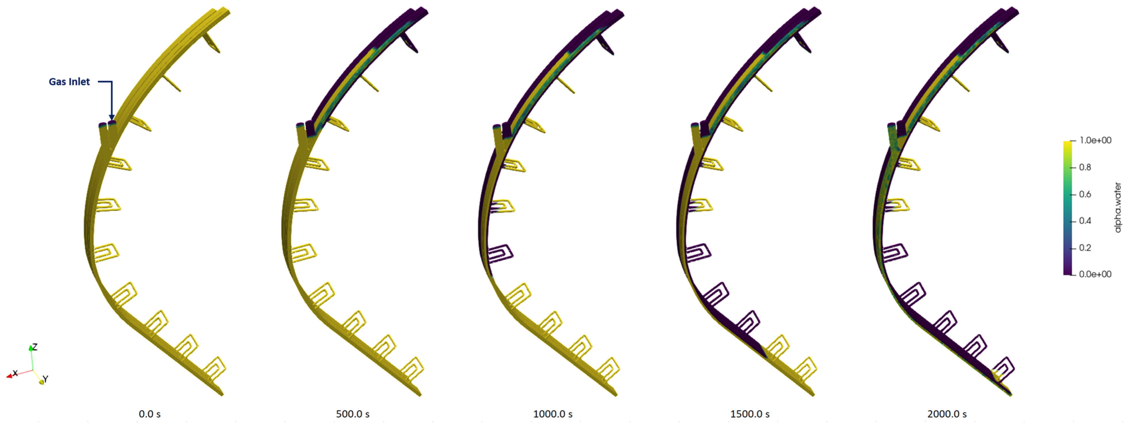
- The BB segment is drained from the top using gas injection. Either gravity, installing a correspondent pipeline at the component bottom, or gas injection can be used to accomplish the objective. The former solution introduces a potential risk source since draining pipe failure would start a severe LOCA sequence, and it is discarded. Nitrogen is assumed as the injection gas.
- BB PHTS is assumed in hot standby mode at transient start, consistently with the LTM assumption. The primary circuit is at an average temperature equal to the minimum system temperature (295 °C [35]) and zero flow.
- Component gas must be injected with enough overpressure to remove water from the blanket. The maximum gas pressure was preliminarily assumed to be equal to the BB PHTSs nominal pressure (15.5 MPa [35]), since exceeding this parameter during an operational procedure was considered not advisable for the system. The water loop must be depressurized to ensure a sufficient differential pressure between gas and water. The BB pressurizers can be used for this purpose. After disabling their nominal pressure control function, described in [36], the depressurization of BZ/FW systems can be accomplished by manually triggering the pilot-operated relief valve (PORV). The pressure target value at the end of the depressurization phase was preliminarily set to 10 MPa, nearly keeping the same subcooling margin characterizing the PHTS in operating conditions [35].
- Gas temperature has been postulated as equal to the water temperature, Tgas = 295 °C. The main reason is to keep the BB internals hot and prevent operation below the ductile/brittle transition temperature due to neutron radiation. In the future, this parameter could be optimized accounting for the power needed to heat the gas up to such a temperature level.
- Water must be driven to a system hosting a storage volume large enough to accommodate all the PHTS inventory. The DEMO WCLL chemical volume control system (CVCS) has been preliminarily identified as the receiving system. Given the large water inventory to be drained (195.3 m³, for both IB and OB), a storage system must be designed and integrated within the CVCS. The corresponding letdown path is connected to the cold leg piping of the BB PHTS, downstream the main circulation pumps, and will be used for the water/gas mixture discharging. Consequently, the gas injection pipeline must be connected to the hot section of the PHTS (e.g., on the sector outlet feeding pipes). To minimize CVCS requirements, we assume that the maximum draining flow is equal to the nominal letdown flow, 0.5% of nominal PHTS flow.
3.2.2. Numerical Models
3.2.3. Results and Discussion
4. Conclusions
Author Contributions
Funding
Acknowledgments
Conflicts of Interest
Abbreviations
| BB | breeding blanket |
| BC | bottom cell |
| BSS | back-supporting structure |
| BU | breeding unit |
| BZ | breeding zone |
| CC | central cell |
| CFD | computational fluid dynamics |
| COB | central outboard blanket |
| CVCS | chemical volume control system |
| DP | draining pipe |
| DWT | double-walled tubes |
| ECH | electron cyclotron heating |
| EM | electro-magnetic |
| EoT | end of the transient |
| EPP | equivalent porous pipe |
| FEM | finite element method |
| FP | feeding pipe |
| FW | first wall |
| GM | global model |
| HCPB | helium-cooled pebble bed |
| IB | inboard blanket |
| IM | inlet manifold |
| LOCA | loss of coolant accident |
| LTM | long term maintenance |
| MHD | magneto hydro-dynamic |
| NO | normal operation |
| OB | outboard blanket |
| OF | open foam |
| OM | outlet manifold |
| OP | over-pressurization |
| PCD | pre-conceptual design |
| PHTS | primary heat transfer system |
| PORV | pilot operated relief valve |
| RAFM | reduced activation ferritic martensitic |
| RANS | Reynolds-averaged Navier–Stokes (equations) |
| REC | recirculation manifold |
| RM | remote maintenance |
| SB | segment box |
| SM | sub-model |
| SP | stiffening plate |
| STH | system thermal–hydraulic |
| SW | side wall |
| TBM | test blanket module |
| TBR | tritium breeding ratio |
| TC | top cell |
| TER | tritium extraction and removal |
| TFC | toroidal field coil |
| UVDE | upper vertical displacement event |
| VV | vacuum vessel |
| WCLL | water-cooled lead lithium |
References
- Morris, W.; Litaudon, X.; Hidalgo, C.; McDonald, D.; Zohm, H.; Federici, G. European Research Roadmap to the Realisation of Fusion Energy; EUROFusion: Garching, Germany, 2018; ISBN 978-3-00-061152-0. [Google Scholar]
- Boccaccini, L.V.; Arbeiter, F.; Arena, P.; Aubert, J.; Bühler, L.; Cristescu, I.; Del Nevo, A.; Eboli, M.; Forest, L.; Harrington, C.; et al. Status of Maturation of Critical Technologies and Systems Design: Breeding Blanket. Fusion Eng. Des 2022, 179, 113116. [Google Scholar] [CrossRef]
- Arena, P.; Del Nevo, A.; Moro, F.; Noce, S.; Mozzillo, R.; Imbriani, V.; Giannetti, F.; Edemetti, F.; Froio, A.; Savoldi, L.; et al. The DEMO Water-Cooled Lead–Lithium Breeding Blanket: Design Status at the End of the Pre-Conceptual Design Phase. Appl. Sci. 2021, 11, 11592. [Google Scholar] [CrossRef]
- Del Nevo, A.; Arena, P.; Caruso, G.; Chiovaro, P.; Di Maio, P.; Eboli, M.; Edemetti, F.; Forgione, N.; Forte, R.; Froio, A.; et al. Recent progress in developing a feasible and integrated conceptual design of the WCLL BB in EUROfusion project. Fusion Eng. Des. 2019, 146, 1805–1809. [Google Scholar] [CrossRef] [Green Version]
- Catanzaro, I.; Bongiovì, G.; Di Maio, P.A. Analysis of the Thermo-Mechanical Behaviour of the EU DEMO Water-Cooled Lithium Lead Central Outboard Blanket Segment under an Optimized Thermal Field. Appl. Sci. 2022, 12, 1356. [Google Scholar] [CrossRef]
- Maviglia, F.; Bachmann, C.; Federici, G.; Franke, T.; Siccinio, M.; Albanese, R.; Ambrosino, R.; Arter, W.; Bonifetto, R.; Calabrò, G.; et al. Integrated design strategy for EU_DEMO first wall protection from plasma transients. Fusion Eng. Des. 2022, 177, 113067. [Google Scholar] [CrossRef]
- Moro, F.; Arena, P.; Catanzaro, I.; Colangeli, A.; Del Nevo, A.; Flammini, D.; Fonnesu, N.; Forte, R.; Imbriani, V.; Mariano, G.; et al. Nuclear performances of the water-cooled lithium lead DEMO reactor: Neutronic analysis on a fully heterogeneous model. Fusion Eng. Des. 2021, 168, 112514. [Google Scholar] [CrossRef]
- Edemetti, F.; Di Piazza, I.; Del Nevo, A.; Caruso, G. Thermal-hydraulic analysis of the DEMO WCLL elementary cell: BZ tubes layout optimization. Fusion Eng. Des. 2020, 160, 111956. [Google Scholar] [CrossRef]
- Fischer, U.; Bachmann, C.; Bienkowska, B.; Catalan, J.; Drozdowicz, K.; Dworak, D.; Leichtle, D.; Lengar, I.; Jaboulay, J.-C.; Lu, L.; et al. Neutronic analyses and tools development efforts in the European DEMO programme. Fusion Eng. Des. 2014, 89, 1880–1884. [Google Scholar] [CrossRef]
- Fischer, U.; Bachmann, C.; Catalan, J.; Eade, T.; Flammini, D.; Gilbert, M.; Jaboulay, J.-C.; Konobeev, A.; Leichtle, D.; Lu, L.; et al. Methodological approach for DEMO neutronics in the European PPPT programme: Tools, data and analyses. Fusion Eng. Des. 2017, 123, 26–31. [Google Scholar] [CrossRef]
- X-5 Monte Carlo Team. MCNP—A General Monte Carlo N-Particle Transport Code; Version 5; Los Alamos National Laboratory: Los Alamos, NM, USA, April 2003. [Google Scholar]
- JEFF3.3 Nuclear Data Library. Available online: http://www.oecd-nea.org/dbdata/jeff/jeff33/#neutron (accessed on 16 February 2022).
- Bachmann, C.; Ciattaglia, S.; Cismondi, F.; Eade, T.; Federici, G.; Fischer, U.; Franke, T.; Gliss, C.; Hernandez, F.; Keep, J.; et al. Overview over DEMO design integration challenges and their impact on component design concepts. Fusion Eng. Des. 2018, 136, 87–95. [Google Scholar] [CrossRef]
- Available online: www.spaceclaim.com (accessed on 8 January 2023).
- Wu, Y.; FDS Team. CAD-based interface programs for fusion neutron transport simulation. Fusion Eng. Des. 2009, 84, 1987–1992. [Google Scholar] [CrossRef]
- Fischer, U.; Boccaccini, L.; Cismondi, F.; Coleman, M.; Day, C.; Hörstensmeyer, Y.; Moro, F.; Pereslalvtsev, P. Required, Achievable and Target TBR for the European DEMO. Fusion Eng. Des. 2020, 155, 111553. [Google Scholar] [CrossRef]
- Allio, A.; Arena, P.; Del Nevo, A.; Savoldi, S. Hybrid modelling for the manifolds and coolant flow distribution in the Water-Cooled Lead-Lithium of the EU-DEMO reactor. In Proceedings of the 19th International Topical Meeting on Nuclear Reactor Thermal Hydraulics (NURETH-19), Brussels, Belgium, 6–11 March 2022. [Google Scholar]
- Catanzaro, I.; Arena, P.; Del Nevo, A.; Di Maio, P.A.; Edemetti, F.; Forte, R.; Martelli, E. Parametric study of the influence of double-walled tubes layout on the DEMO WCLL breeding blanket thermal performances. Fusion Eng. Des. 2020, 161, 111893. [Google Scholar] [CrossRef]
- Melchiorri, L.; Narcisi, V.; Giannetti, F.; Caruso, G.; Tassone, A. Development of a RELAP5/MOD3.3 module for MHD pressure drop analysis in liquid metals loops: Verification and Validation. Energies 2021, 14, 5538. [Google Scholar] [CrossRef]
- Smolentsev, S. Physical background, computations and practical issues of the magnetohydrodynamic pressure drop in a fusion liquid metal blanket. Fluids 2021, 6, 110. [Google Scholar] [CrossRef]
- Melchiorri, L.; Narcisi, V.; Ciurluini, C.; Giannetti, F.; Caruso, G.; Tassone, A. Preliminary MHD pressure drop analysis for the prototypical WCLL TBM with RELAP5/MOD3.3. Fusion Eng. Des. 2022, 176, 113048. [Google Scholar] [CrossRef]
- Tassone, A.; Caruso, G.; Del Nevo, A. Influence of PbLi hydraulic path and integration layout on MHD pressure losses. Fusion Eng. Des. 2020, 155, 111517. [Google Scholar] [CrossRef]
- Tassone, A.; Siriano, S.; Caruso, G.; Utili, M.; Del Nevo, A. MHD pressure drop estimate for the WCLL in-magnet PbLi loop. Fusion Eng. Des. 2020, 160, 111830. [Google Scholar] [CrossRef]
- Sedlak, K.; Anvar, V.; Bagrets, N.; Biancolini, M.E.; Bonifetto, R.; Bonne, F.; Boso, D.P.; Brighenti, A.; Bruzzone, P.; Celentano, G.; et al. Advance in the conceptual design of the European DEMO magnet system. Supercond. Sci. Technol. 2020, 33, 044013. [Google Scholar] [CrossRef]
- Martelli, D.; Venturini, A.; Utili, M. Literature review of lead-lithium thermophysical properties. Fusion Eng. Des. 2019, 138, 183–195. [Google Scholar] [CrossRef]
- Bühler, L.; Mistrangelo, C. A simple MHD model for coupling poloidal manifolds to breeder units in liquid metal blankets. In Proceedings of the 32nd Symposium on Fusion Technology (SOFT), Dubrovnik, Croatia, 18–23 September 2022. [Google Scholar]
- Siriano, S.; Tassone, A.; Melchiorri, L.; Caruso, G.; Arena, P. Numerical analysis of extreme magnetoconvective phenomena in the WCLL blanket. In Proceedings of the 32nd Symposium on Fusion Technology (SOFT), Dubrovnik, Croatia, 18–23 September 2022. [Google Scholar]
- Yan, Y.; Alice, Y.; Abdou, M. Numerical study of magneto-convection flows in a complex prototypical liquid-metal fusion blanket geometry. Fusion Eng. Des. 2020, 159, 111688. [Google Scholar] [CrossRef]
- Urgorri, F.R.; Fernández-Berceruelo, I.; Rapisarda, D. Magneto-Convective Analyses of the PbLi Flow for the EU-WCLL Fusion Breeding Blanket. Energies 2021, 14, 6192. [Google Scholar] [CrossRef]
- Iannone, F.; Ambrosino, F.; Bracco, G.; De Rosa, M.; Funel, A.; Guarnieri, G.; Migliori, S.; Palombi, F.; Ponti, G.; Santomauro, G.; et al. CRESCO ENEA HPC clusters: A working example of a multifabric GPFS Spectrum Scale layout. In Proceedings of the 2019 International Conference on High Performance Computing & Simulation (HPCS), Dublin, Ireland, 15–19 July 2019; pp. 1051–1052. [Google Scholar]
- Catanzaro, I.; Bongiovì, G.; Chiovaro, P.; Di Maio, P.A.; Spagnuolo, G.A. Development and application of an alternative modelling approach for the thermo-mechanical analysis of a DEMO Water-Cooled Lithium Lead Breeding Blanket Segment. Fusion Eng. Des. 2022, 180, 113195. [Google Scholar] [CrossRef]
- AFCEN. RCC-MRx, Design and Construction Rules for Mechanical Components of Nuclear Installations; AFCEN: Courbevoie, France, 2013. [Google Scholar]
- Tran, M.Q.; Agostinetti, P.; Aiello, G.; Avramidis, K.; Baiocchi, B.; Barbisan, M.; Bobkov, V.; Briefi, S.; Bruschi, A.; Chavan, R.; et al. Status and future development of Heating and Current Drive for the EU DEMO. Fusion Eng. Des. 2022, 180, 113159. [Google Scholar] [CrossRef]
- Pinna, T.; Dongiovanni, D.N. Approach in improving reliability of DEMO. Fusion Eng. Des. 2020, 161, 111937. [Google Scholar] [CrossRef]
- Barucca, L.; Hering, W.; Martin, S.P.; Bubelis, E.; Del Nevo, A.; Di Prinzio, M.; Caramello, M.; D’Alessandro, A.; Tarallo, A.; Vallone, E.; et al. Maturation of critical technologies for the DEMO balance of plant systems. Fusion Eng. Des. 2022, 179, 113096. [Google Scholar] [CrossRef]
- Ciurluini, C.; Giannetti, F.; Del Nevo, A.; Caruso, G. Study of the EU-DEMO WCLL Breeding Blanket Primary Cooling Circuits Thermal-Hydraulic Performances during Transients Belonging to LOFA Category. Energies 2021, 14, 1541. [Google Scholar] [CrossRef]
- Idaho National Laboratory; The RELAP5-3D© Code Development Team. RELAP5-3D© Code Manual: Code Structure, System Models, and Solution Methods; Revision 4.3, INL-MIS-15-36723; Idaho National Laboratory: Idaho Falls, ID, USA, 2015; Volume I.
- OpenFOAM Foundation. OpenFoam v. 9, C++ Source Guide. Available online: https://cpp.openfoam.org/v9/interFoam_8C_source.html (accessed on 24 June 2022).


| Parameter | Value |
|---|---|
| N° of toroidal field coils | 16 |
| Major radius (m) | 8.938 |
| Minor radius (m) | 2.883 |
| Aspect ratio | 3.1 |
| Plasma elongation | 1.65 |
| Plasma triangularity | 0.33 |
| Fusion power | 1998 |
| Average neutron wall loading (MW/m²) | 1.04 |
| Net electric power | 500 |
| Parameter | DWT 1 | DWT 2 |
|---|---|---|
| N° of tubes in COB elementary cell | 6 | |
| Number of windings | 2.5 | |
| Distance from FW | 10.0 mm | 46.0 mm |
| Total length (in BZ) | 2506.1 mm | 2353.6 mm |
| Toroidal dimension | 226.5 mm | 106.5 mm |
| Poloidal dimension | 120.0 mm | 117.5 mm |
| Radial inlet–outlet part | 476.7 mm | 440.7 mm |
| Curvature radius | 46.5 mm | |
| Helix inclination | 4.95° | |
| Parameter | Value | Unit |
|---|---|---|
| FW water total mass flow rate | 0.63 | kg/s |
| BZ water total mass flow rate | 0.21 | kg/s |
| DWTs average outlet T | 327.5 | °C |
| FW average outlet T | 328.7 | °C |
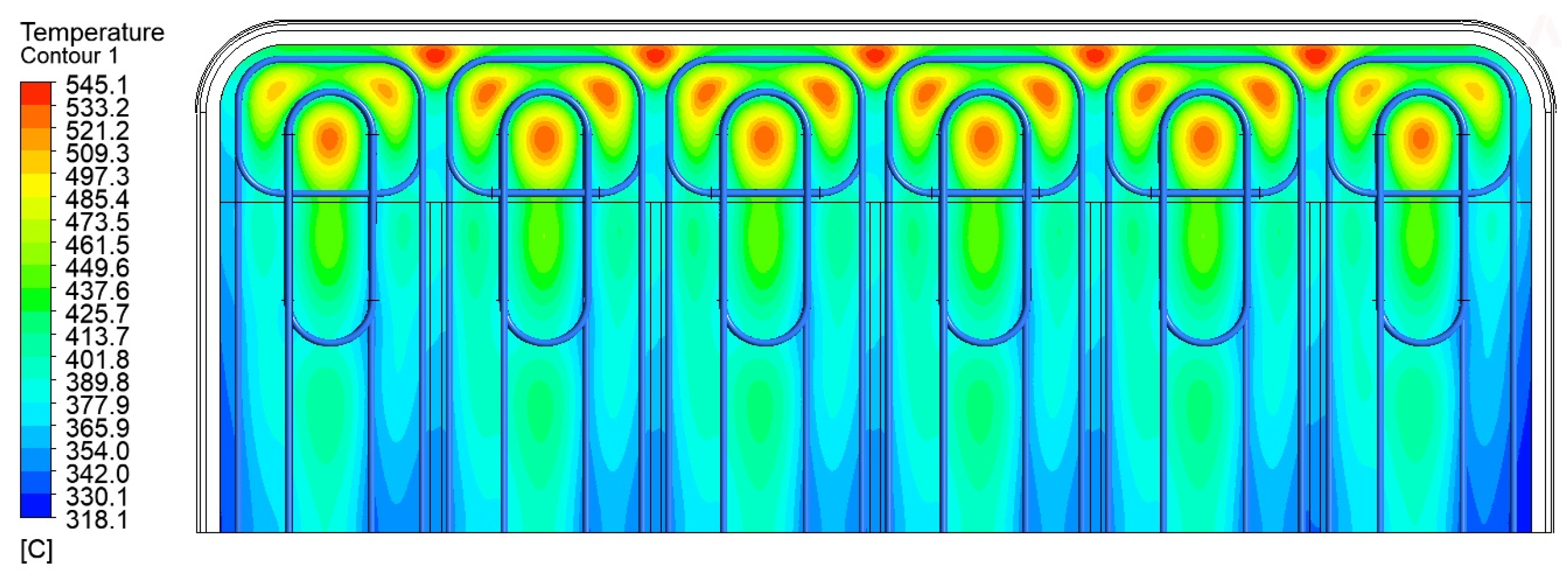
| Max T in Plates | 545.1 | °C |
| Max T in FW | 529.5 | °C |
| Max T in Pb-Li | 618.3 | °C |
| Pressure drops in DWT-1 | 0.260 | bar |
| Pressure drops in DWT-2 | 0.147 | bar |
| Area | OB | IB | ||
|---|---|---|---|---|
| This study | Ref. [23] | This study | Ref. [23] | |
| FP | 581 | 613 | 1499 | 1557 |
| BC | 422 | 122 | 84 | 92 |
| IN MAN | 136 | 68 | 275 | 328 |
| BZ | 5 | n/a | 17 | n/a |
| OUT MAN | 148 | 190 | 275 | 122 |
| TC | 30 | 55 | 5 | 76 |
| SC | 718 | 444 | null | null |
| DP | 303 | 429 | 428 | 260 |
| TOT | 2343 | 1921 | 2583 | 2435 |
| STH | CFD | |
|---|---|---|
| DWTs () | 0.31 | 0.39 |
| Inlet Spinal Collector | 0.83 | - |
| Inlet Manifold | 0.01 | - |
| Distribution Manifold | 0.01 | - |
| Outlet Manifold | 0.01 | - |
| Outlet Spinal Collector | 0.47 | - |
| Total Manifold () | 0.21 | 0.29 |
| Total COB Segment () | 0.21 | 0.29 |
Disclaimer/Publisher’s Note: The statements, opinions and data contained in all publications are solely those of the individual author(s) and contributor(s) and not of MDPI and/or the editor(s). MDPI and/or the editor(s) disclaim responsibility for any injury to people or property resulting from any ideas, methods, instructions or products referred to in the content. |
© 2023 by the authors. Licensee MDPI, Basel, Switzerland. This article is an open access article distributed under the terms and conditions of the Creative Commons Attribution (CC BY) license (https://creativecommons.org/licenses/by/4.0/).
Share and Cite
Arena, P.; Bongiovì, G.; Catanzaro, I.; Ciurluini, C.; Collaku, A.; Del Nevo, A.; Di Maio, P.A.; D’Onorio, M.; Giannetti, F.; Imbriani, V.; et al. Design and Integration of the EU-DEMO Water-Cooled Lead Lithium Breeding Blanket. Energies 2023, 16, 2069. https://doi.org/10.3390/en16042069
Arena P, Bongiovì G, Catanzaro I, Ciurluini C, Collaku A, Del Nevo A, Di Maio PA, D’Onorio M, Giannetti F, Imbriani V, et al. Design and Integration of the EU-DEMO Water-Cooled Lead Lithium Breeding Blanket. Energies. 2023; 16(4):2069. https://doi.org/10.3390/en16042069
Chicago/Turabian StyleArena, Pietro, Gaetano Bongiovì, Ilenia Catanzaro, Cristiano Ciurluini, Aldo Collaku, Alessandro Del Nevo, Pietro Alessandro Di Maio, Matteo D’Onorio, Fabio Giannetti, Vito Imbriani, and et al. 2023. "Design and Integration of the EU-DEMO Water-Cooled Lead Lithium Breeding Blanket" Energies 16, no. 4: 2069. https://doi.org/10.3390/en16042069