1. Introduction
After the Kigali Amendment to the Montreal Protocol, the usage of the HCFC refrigerant was reduced and eventually eliminated, because of the high global warming potential (GWP). At present, the HFC refrigerant (R134a) widely used in electrical vehicles has a very high greenhouse effect, and GWP is usually 1000~2000 times that of CO
2. Therefore, the substitution of refrigerants [
1] and the improvement efficient [
2] of electric vehicle heat pump systems are an urgent need for our environment.
CO2 is a natural working medium (ODP = 0, GWP = 1) and the physical properties of CO2 are very suitable for use as a refrigerant. The components of R744 are smaller than traditional refrigerant considering its huge latent heat in evaporating and its high volumetric refrigeration capacity. The ratio of liquid density to steam density is small. After throttling, the refrigerant is evenly distributed in each pipe. A low operating viscosity can form turbulence in the flow channel to improve the heat transfer performance. In addition, it has other noteworthy advantages, such as being non-toxic, chemically stable, non-flammable, and having an easy production.
During the subcritical cycle, because of the low discharge temperature (31.1 °C, 73.7 bar) of CO
2, it will cause the attenuation of capacity and efficiency. Lorentzen [
3] proposed a transcritical cycle for automobiles in 1990. Later, Lorentzen and Petterson revived CO
2 as a refrigerant of air conditioning systems in 1993 [
4,
5,
6] and verified its feasibility, but the refrigeration effect was poor and the development was hindered. Because the range of electric vehicles is decreased at low temperatures, and there is no residual heat from the engine that can be used, and the transcritical CO
2 cycle has once again come into consideration because of its strong heating characteristics.
In recent years, scholars have carried out a lot of optimization research in order to improve the performance of CO
2 in the field of thermal management. For example, Yin [
7] et al. carried out optimization research on the filling amount of a CO
2 transcritical refrigeration system under different working conditions, and proposed the concept of the filling rate. The performance of the system under the condition of under charging, appropriate charging, and overcharge showed that under charging and overcharging would cause greater attenuation to the system performance.
Scientific research institutions such as the University of Illinois [
8] and the University of Maryland [
9], as well as enterprises such as Sanye [
10] and Nissan [
11], have studied the cooling capacity of CO
2 and R134a under full ambient temperature and different driving conditions and verified that CO
2 automotive air conditioners can obtain the same cooling capacity as R134a, but their energy efficiency is slightly lower under idling, urban, and high temperature conditions. In terms of their cooling effect, in 2000, Japan’s Kassonic Company released the results at the International Conference on Alternative Refrigerants for the Automotive Industry, which showed that the cooling capacity of the CO
2 passenger car air conditioning system was not lower than that of the R134a system [
12]. Subsequently, R.H.H. Mager showed that the CO
2 system could provide a lower compartment temperature and shorter rapid cooling time [
13]. S. Memory et al. [
14] conducted a cooling experiment on a BMW 328i car. The results showed that the faster cooling time of the transcritical CO
2 air conditioning system was shortened by nearly 15 min compared with R134a. At the same time, the experimental results of A. Dragi [
15] show that the air supply temperature at the evaporator side of the CO
2 system was 6 °C lower than R134a after rapid cooling. The heating characteristics of the transcritical CO
2 cycle were obviously superior to the R134a system.
In order to further promote the CO
2 heat pump air conditioning system for vehicles and make the products more compact and lightweight, Dong et al. [
16] developed and used the transcritical CO
2 four-way valve, integrated gas separator regenerator, and various microchannel heat exchangers. The results show that the heating capacity of the transcritical CO
2 system was significantly improved, and still had a stable heating capacity at temperatures as low as −25 °C. At −10 °C, the heating capacity could still be increased by 80% compared with R134a. The integration scheme reduced the products in the aspect of the weight and volume, and make outstanding contributions to the industrialization of the CO
2 heat pump system.
Many scholars [
17,
18,
19] have shown that there is an optimal high-pressure for transcritical CO
2 automotive air conditioners under cooling conditions, as well as control of high-pressure side pressure. In order to keep the high-pressure side pressure at the optimal value, they changed the charging amount and changed the compressor outlet pressure using back pressure valves or electronic expansion valves and other methods. Casson [
20] used the differential valve to control the pressure at the high-pressure side by twice throttling. The differential valve is located at the front end of the gas–liquid separator, which is used to throttle the supercritical CO
2 gas to the saturated state. The saturated CO
2 enters the gas–liquid separator, and the expansion valve throttles the saturated liquid CO
2. This method mainly uses appropriate differential pressure at both ends of the differential valve to control the pressure to reach the optimal value.
In this study, the COP and cooling/heating capacity of the R744 system was evaluated, based on the new CO2 heat pump system in a real structure. The main objectives of this study are as follows. One is to prove the cooling and heating capacity of R744 system under extreme conditions. The second is to show that the R744 system can meet the capacity requirement of a 10 KW battery fast charging at a high temperature. The third is to analyze the impact of each parameter on the system energy consumption, and to provide a direction for system optimization and optimal energy consumption control.
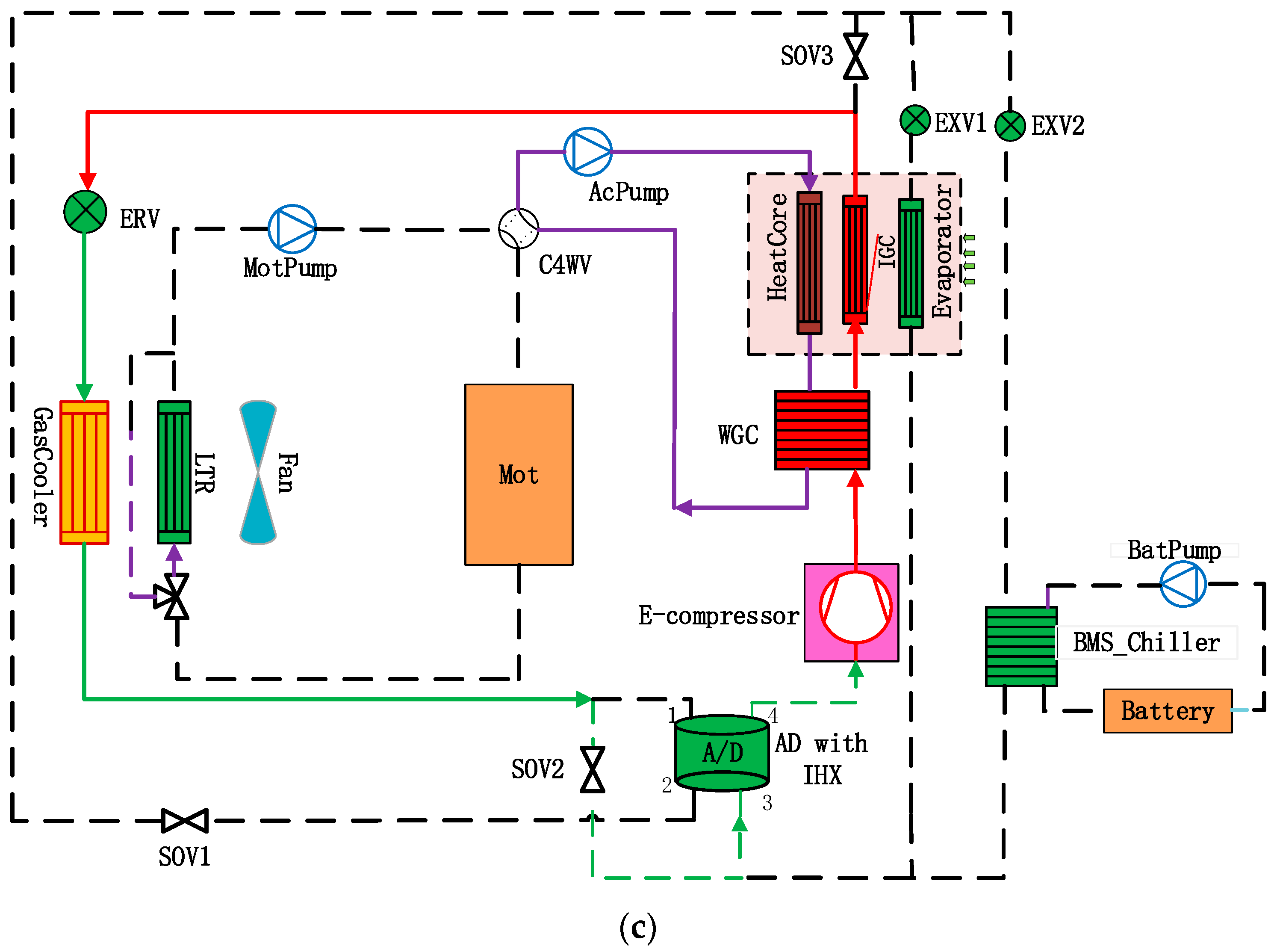
2. Theoretical Analysis of Heat Pump Loop
The designed heat pump system can realize the function of cooling, dehumidification, and heating for a cabin. In addition, the battery side is equipped with a faster charging system. The main components include an electrical compressor, water gas cooler (WGC), inner gas cooler (IGC), outer gas cooler (OGC), BMS Chiller, EXV, accumulator with internal heat exchanger (IHX), SOV, and ERV.
The advantages of this system are as follows. The heat pump can achieve three basic functions by using three stop valves (SOV). The component of ERV makes the heat pump system simpler, which embraces the full pass and throttling function. In the cooling or heating mode, the capacity can be increased through the water-cooled condenser. In the dehumidification heating mode, the designed loop can dissipate excess heat from WGC. Finally, it has the advantages of being a direct and indirect heat pump system.
For the cooling mode (
Figure 1a), the E compressor in the R744 system controls the required temperature. EXV1 is used to control the discharge pressure of the compressor in order to obtain the maximum COP. In the cooling mode, ERV is fully opened for heat dissipation by OGC. Different from the heat pump systems on the market, this heat pump system connects a water-cooled condenser between the compressor outlet and the indoor air cooler. This measure will greatly improve the heat exchange capacity and energy efficiency of the R744 system. The theoretical analysis is as follows: when the R744 heat pump is in refrigeration, the high-pressure side operates in a transcritical state, and the temperature at the high-pressure side continues to decrease, and the huge temperature slip increases the average heat transfer temperature difference between the refrigerant side and the water side. When the system needs a medium cooling capacity, the system can flexibly choose to use only the outdoor air cooler for heat dissipation, further saving the power of the passenger compartment water pump and motor water circuit.
For the dehumidification mode (
Figure 1b), an indoor evaporator and outdoor heat exchanger are used as the evaporator at the same time. The indoor side evaporator can be dehumidified to ensure that the passenger compartment is not foggy. The outdoor heat exchanger is used for the evaporator to absorb more heat from the outside and disperse it to the passenger compartment side. Because this mode often operates in spring and autumn, when the heat load required by the passenger compartment is very small, even if the full-way throttle valve in front of the outdoor heat exchanger is closed, the supply power is still greater than the passenger demand, and the system can flexibly dissipate the excess heat to the outdoor low-temperature heat exchanger side, thus ensuring dehumidification and comfort in the passenger compartment.
Under a low temperature or extremely low temperature heating conditions (
Figure 1c), the compressor controls the target demand air temperature, and the ERV regulates the pressure on the high-pressure side to ensure that the system operates at an optimal pressure. The heat pump systems on the market are mainly divided into indirect and direct systems. The indirect heat pump first dissipates the heat to the water side, heats the heating core through water, and the direct heat pump directly flows the refrigerant into the inner gas cooler for heating. In terms of heating speed, the direct is obviously improved compared to the indirect heat pump, but in terms of system stability, the indirect heat pump has greater advantages when the system is disturbed due to the large specific capacity and inertia at the water side. This scheme fully combines the advantages of the indirect heat pump and direct heat pump, increases the heat exchange area and quickly dissipates more heat to the passenger compartment side. During the early heating period, only the indoor air cooler is used for heating. After the outlet temperature reaches the required temperature, the indirect heating circuit is gradually opened to provide more heat to the interior of the cabin.
4. Experimental Results and Discussion for R744 HP Systems
In order to thoroughly know the features of the heat pump, the system capacity and COP of the heating and cooling were tested in low temperature and high temperature environments, respectively, and experiments were then conducted by changing the parameters to analyze the impact on the system, so we could have a comprehensive understanding of the system. At a low temperature, the experimental study was conducted at ambient temperatures of −7 °C, −15 °C, and −20 °C. At a high temperature, the refrigeration experiment was conducted at 40 °C and 35 °C. At the same time, the Chiller cooling capacity was tested at the ambient temperature of 30 °C, 40 °C, and 45 °C to verify the feasibility of the R744 refrigerant used in rapid charge cooling.
4.1. Cooling Performance of R744 HP System
In order to obtain the evaluation of the cooling performance of the R744 heat pump under an ambient high temperature, first, the indoor and outdoor air inlet temperature were 40 °C, the outdoor air inlet volume was 3 m/s, and the indoor air inlet volume was 500 m3/h. At the same time, WGC was opened, the water flow was 10 L/min, and the water inlet temperature was 52 °C. Secondly, air inlet was conducted at an ambient temperature of 35 °C and the indoor air inlet was conducted at 27 °C to simulate the internal circulation state of the real vehicle. Finally, the cooling capacity of the chiller at various ambient temperatures was studied.
4.1.1. The Effects of Discharge Pressure on the Cooling Performance for R744 HP System at 40 °C
For the sake of obtaining the impact of discharge pressure on the system energy efficiency, the experimental research was conducted with working conditions, ambient temperature of 40 °C, indoor air inlet temperature of 40 °C, relative humidity of 40%, air inlet volume of 500 m
3/h, outside gas cooler air inlet temperature of 40 °C, and air inlet speed of 3 m/s. The compressor controlled the air outlet temperature of 18 °C to achieve the same cooling capacity of 8.2 kW. By changing EXV1, the high pressure was controlled to 105 barA, 110 barA, 115 barA, and 120 barA, respectively, and the system COP was compared. The experimental results, as shown in
Figure 4, indicate that when the high pressure was 110 barA, the COP value of the system energy efficiency was the highest, reaching 1.87, and it then decreased to 1.73 with the increase in high pressure. This conclusion shows the importance of optimal pressure.
4.1.2. The Effects of Discharge Pressure on the Cooling Performance for R744 HP System at 35 °C with an Indoor Inlet Air Temperature of 27 °C
In order to comprehend the change rule of system energy efficiency for the R744 heat pump system during the internal circulation of refrigeration, further experiments were conducted when the outdoor inlet air temperature was 35 °C, air speed was 3 m/s, indoor inlet air volume was 420 m
3/h, inlet air temperature was 27 °C, and relative humidity was 40%. At the same cooling capacity of 3.4 kW, the compressor controlled the air outlet temperature at 12 °C, which means the same cooling capacity of 3.4 KW was obtained. EXV1 controlled the exhaust pressure at 85 barA, 87.5 barA, 90 barA, and 92.5 barA, respectively. The results are shown in
Figure 5. When the exhaust pressure was 87.5 barA, the system COP value was the highest, reaching 2.36.
4.1.3. The Performance of Chiller Used for Battery Fast Cooling
In order to apply the R744 heat pump system to the battery fast charging cooling, the system cooling test was carried out at an ambient temperature of 30 °C, 40 °C, and 45 °C. The outdoor air inlet speed was uniformly 3 m/s, the water inlet flow at the chiller side was 25 L/min, and the water inlet temperature was 23.3 °C. As shown in
Figure 6, when the ambient temperature was 30 °C, the compressor was 7000 rpm, the exhaust pressure was 120 barA, and the chiller cooling capacity could easily reach 13 kW; when the ambient temperature was 40 °C, the high pressure needed to be controlled at 125 barA; when the compressor was 7500 rpm, the chiller cooling capacity could reach 11 kW. When the ambient temperature was 45 °C, the high pressure was controlled at 125 barA, the compressor was 7500 rpm, and the cooling capacity of the chiller reached 9 kW.
This means that the R744 system could provide a sufficient cooling capacity when the battery was fast charged.
4.2. Heating Performance of the R744 HP System
As declared in [
25], the endurance of new energy electric vehicles at low temperatures is seriously affected by the attenuation of the battery capacity and the increase in thermal load required in the passenger compartment. Moreover, conventional refrigerants, such as R134a, need a lower evaporation temperature if they are to absorb heat from the environment after being lower than the ambient temperature of −10 °C. The suction pressure is close to the atmospheric pressure, which has the risk of absorbing air. In this way, PTC heating only consumes electric energy for heating, and does not absorb heating from air. Due to the loss of heat energy, PTC heating results in efficiency less than 1 and further increases the energy consumption of the air conditioning system.
In this part, first of all, system research was carried out under an ambient temperature of −7 °C. On the premise of obtaining the same heating capacity, the change rule of the system energy consumption was studied by changing the water flow rate at the side of the heating core, different discharge pressures, different indoor air volumes, and different outdoor air volumes. Based on this rule, the maximum capacity test was carried out under a working condition of −7 °C. Then, we studied the maximum system capacity and COP at an ambient temperature of −15 °C, and tested the maximum system capacity at −20 °C.
4.2.1. Heating Performance (at −7 °C) Parameter Influence Experiment
In order to fully understand the influence of each variable on the R744 heat pump system, on the basis of the same heating capacity, we changed the water flow at the side of the system heating core, the air inlet speed of the outdoor heat exchanger, the air inlet volume of different HVAC, and the air outlet pressure, respectively, to obtain the change rule for the system COP.
When the indoor and outdoor air inlet temperature was −7 °C, the HVAC air inlet volume was 200 m
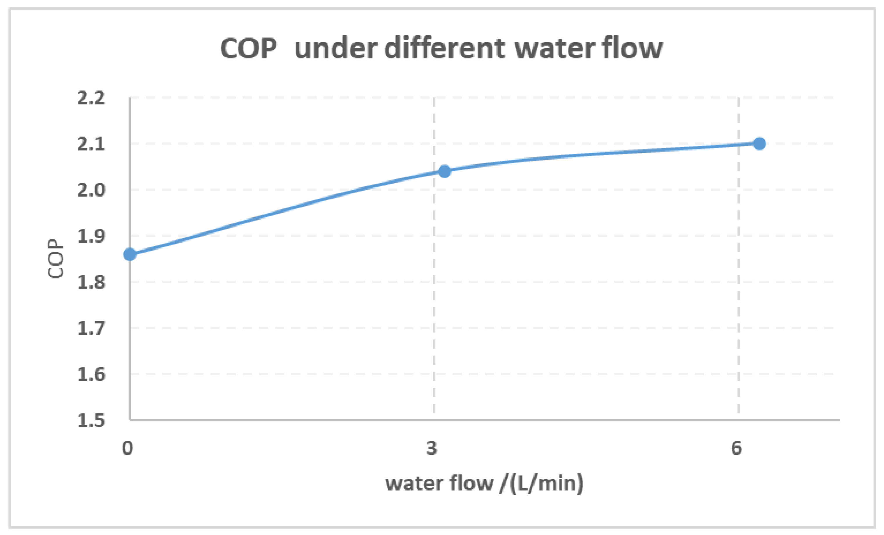
3/h, and the wind speed was 3 m/s, and discharge pressure of 80 barA was taken as the test pressure point. In order to reach the same air outlet temperature of 40 °C, we changed the water flow of the heating air core from 0 L/min to 3 L/min, 6 L/min, and obtained the system COP change rule. The experimental results in
Figure 7 show that after the water flow rate increased from 0 L/min to 3 L/min, the COP value of the system had a significant increase from 1.86 to 2.04. After the water flow rate was further increased to 6 L/min, the COP value still increased, from 2.04 to 2.1, with a small increase. This shows that at 3 L/min, the heat transfer capacity of the heating air core was close to the maximum, and the capacity would not be greatly improved if the water flow increased subsequently.
Based on the influence of water flow research on the system, 3 L/min was taken as the experimental flow when the other variables below were studied.
When the indoor and outdoor air inlet temperature was −7 °C, the HVAC air inlet volume was 200 m
3/h, and the wind speed was 3 m/s, and the water flow of the heating air core was 3 L/min. In order to reach the same air outlet temperature of 40 °C, the discharge pressure was 80 barA, 85 barA, and 90 barA, respectively, so as to obtain the system COP change rule. The experimental results (
Figure 8) show that with the increase in exhaust pressure from 80 bar A to 90 bar A, the COP of the system increased first and then decreased, indicating that there was an optimal COP pressure. Cause analysis: with the increase in discharge pressure, the enthalpy value at the outlet of the air cooler gradually decreased. Under the same heat exchange rate, the mass flow required by the system decreased, and the compressor speed decreased. If the enthalpy value at the outlet of the air cooler decreased more than the compressor consumption, the COP value would increase. If the decrease in enthalpy value was far less than the increase in work consumption caused by the increase in compressor differential pressure, the COP value would decrease.
At present, in order to improve the endurance mileage of new energy electric vehicles, most of them adopted the method of mixed vehicle interior temperature to increase the HVAC inlet air temperature. In the same way, in this experiment, research on the HVAC inlet air temperature of 5 °C was carried out, and the system COP change rule was studied under the conditions of 80 bar A, 85 bar A, 90 bar A, and 95 bar A. From
Figure 8, the results show that the COP of the system also showed a trend of increasing first and then decreasing with the 5 °C air inlet scheme, and the maximum COP was 1.96.
By comparing the COP value of the system at the inlet air temperature of −7 °C and 5 °C, the COP value at −7 °C was significantly higher than that at 5 °C under the same exhaust pressure. The cause analysis shows that at −7 °C, the heat transfer temperature difference at the high pressure side was enhanced, and the system energy efficiency was improved. However, at the same outlet temperature, the heating capacity required for the inlet air at 5 °C was significantly lower than that at −7 °C.
To study the influence of different indoor air volumes on the system performance, we used 150 m
3/h, 200 m
3/h, and 250 m
3/h as the air intake volumes, individually, under working conditions of indoor and outdoor air inlet temperature of −7 °C and outdoor air inlet speed of 3m/s, in order to study the relationship between the system COP and the indoor air intake volume. Because R744 has an optimal pressure when it crosses the critical value, exhaust pressures of 80 barA, 85 barA, 90 barA, and 95 barA were selected, separately, for the systematic research. The results (
Figure 9) show that under the same air volume, the optimal COP value of the system increased first and then decreased with the increase in exhaust pressure. Under different indoor air intake volumes, the optimal COP value of the system was concentrated around 90 barA. This conclusion could be applied to the optimal pressure control of the whole R744 vehicle. At the same time, it also shows that under the same air outlet temperature, a large air volume could increase the system heating capacity. At this time, the COP value was large. With the increase in temperature in the vehicle, the passenger compartment demand air volume gradually decreased. At this time, the system COP value gradually decreased, and the demand heating capacity also gradually decreased.
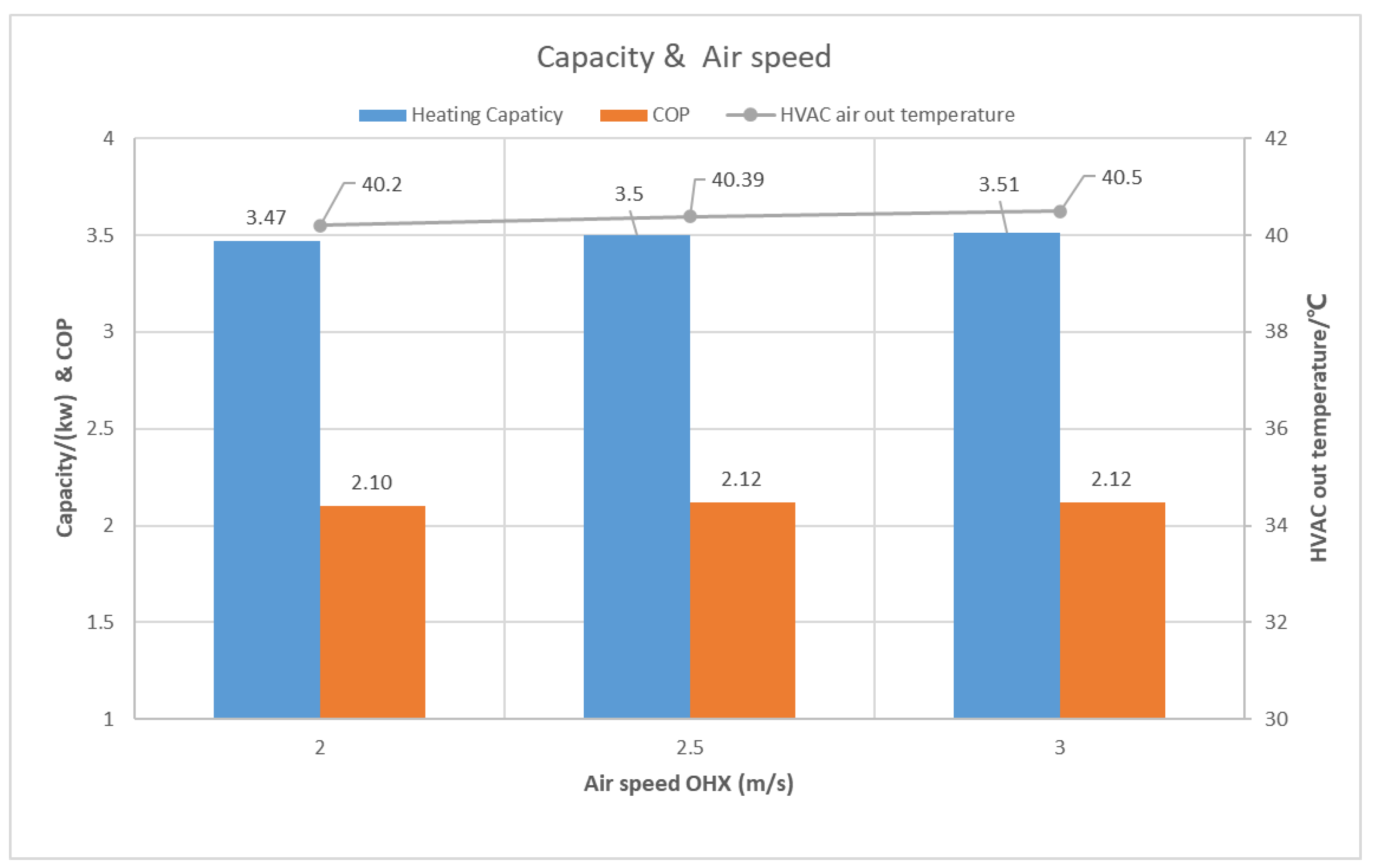
In order to study the influence of the air inlet speed on the system, the relationship between the system’s heating capacity and COP was studied when the indoor and outdoor air inlet temperatures were −7 °C, the indoor air inlet volume was 200 m
3/h, the water flow of the warm air core was 3 L/min, and the compressor’s fixed speed was 2500 rpm. The system’s high pressure was maintained at 90 barA by adjusting the ERV opening. The air inlet speed of the outdoor heat exchanger was 2 m/s, 2.5 m/s, and 3 m/s, respectively. The experimental results (
Figure 10) show that, with the increase in the outdoor air inlet speed, the system heating capacity slightly increased. When the wind speed increased from 2 m/s to 3 m/s, the heating capacity increased from 3470 W to 3496. The air outlet temperature increased from 40.2 °C to 40.5 °C, and the COP value increased from 2.10 to 2.12. The whole test results show that the change in outdoor air inlet speed had little effect on the system heating and energy efficiency.
4.2.2. Heating Performance (−15 °C) at Different Discharge Pressures under the Same Heating Capacity
When the indoor and outdoor air inlet temperature was −15 °C at the same time, the indoor air inlet volume was 200 m
3/h and the outdoor air inlet speed was 3 m/s, and the COP performance of the system under different pressures was studied under the same heating capacity, that is, the same air outlet temperature. The results show, as seen in
Figure 11, that under this working condition, the R744 heat pump system could achieve a 5.07 kW heat exchange capacity, HVAC outlet air temperature of 50 °C, and system COP of 1.78. During the process of discharge pressure increasing from 85 bar A to 90 bar A to 95 bar A, the COP of the system kept increasing, but the increasing trend was more and more slow.
4.2.3. Heating Performance at −20 °C
Under the condition that the indoor and outdoor air inlet temperature was −20 °C, the air inlet volume of the air conditioning box was 300 m
3/h, and the outdoor air inlet speed was 3 m/s, the maximum capacity of the system was tested under the conditions that the water flow of the heating air core was 3 L/min and 6 L/min, respectively. The test results show that at −20 °C, when the compressor speed was 7500 rpm, the maximum heating capacity of the system was 6.86 kW (
Figure 12), the COP value was 1.67, and the indoor air outlet temperature could reach 38.4 °C. At this time, the maximum capacity of the system was limited by the 135 °C protection point of the exhaust temperature, and the isentropic efficiency of the compressor was only 0.57. If the isentropic efficiency of the R744 compressor under a high-pressure difference could be improved, the heating capacity and COP of the R744 heat pump system would be further improved. When the flow rate increased from 3 L/min to 6 L/min, the heating capacity of the whole system did not increase much. This result is same as the test result when changing the water flow at ambient temperature of −7 °C. The cause analysis showed that the heat exchange reached the maximum at 3 L/min when the inlet water temperature of the heating core was at a certain early stage. If more heat exchange was needed, a larger COP value could increase the HVAC air volume. Furthermore, under the working condition of −20 °C ambient temperature, the heat transfer performance of the system was not affected by increasing the water flow at the heating side, which could provide a theoretical basis for the flow control of −20 °C ambient temperature.
In a word, the R744 heat pump has great potential in the for future electric vehicles, because of its considerable heating capacity and COP.
4.3. Dehumidifying Mode Performance
For the optimal COP under different operation conditions, COP was increased from 3.3 to 4.2 with the air temperature from 10 °C to 4.2 °C, as declared in [
26]. In this study, we focused on the deep performance of the system under extreme conditions that had a high energy consumption and strongly affected the vehicle range. In future work, we will study the minimum capacity between the passenger compartment and HP system under mild conditions.


