Article

Investigation of the Mechanical Behavior of a New Generation Wind Turbine Blade Technology

by
Cihan Çiftci
1,2,
Ayşe Erdoğan
3 and
Mustafa Serdar Genç
3,4,*
1
Department of Civil Engineering, Abdullah Gul University, Kayseri 38080, Turkey
2
Techno-CC R&D Innovation Ltd. Co., Erciyes Teknopark, Kayseri 38039, Turkey
3
Wind Engineering and Aerodynamic Research Center, Department of Energy Systems Engineering, Erciyes University, Kayseri 38039, Turkey
4
Energy Conversion Research and Application Center, Erciyes University, Kayseri 38039, Turkey
*
Author to whom correspondence should be addressed.
Energies 2023, 16(4), 1961; https://doi.org/10.3390/en16041961
Submission received: 28 January 2023 / Revised: 10 February 2023 / Accepted: 13 February 2023 / Published: 16 February 2023
(This article belongs to the Special Issue Advances in Wind Energy and Wind Turbines)

Abstract

:
Wind turbine blades are one of the largest parts of wind power systems. It is a handicap that these large parts of numerous wind turbines will become scrap in the near future. To prevent this handicap, newly produced blades should be recyclable. In this study, a turbine blade, known as the new generation of turbine blade, was manufactured with reinforced carbon beams and recycled, low-density polyethylene materials. The manufacturing addressed in this study reveals two novelties: (1) it produces a heterogeneous turbine blade; and (2) it produces a recyclable blade. In addition, this study also covers mechanical tests using a digital image correlation (DIC) system and modeling investigations of the new generation blade. For the mechanical tests, displacement and strain data of both new generation and conventional commercial blades were measured by the DIC method. Instead of dealing with the modeling difficulty of the new generation blade’s heterogeneity we modeled the blade structural system as a whole using the moment–curvature method as part of the finite element method. Then, the behavior of both the new generation and commercial blades at varying wind speeds and different angles of attack were compared. Consequently, the data reveal that the new generation blades performed sufficiently well compared with commercial blades regarding their stiffness.

1. Introduction

Increasing environmental concern about the harmful consequences of global warming and carbon emissions has recently created new demands for renewable and sustainable energy sources such as wind, solar, biomass and geothermal energy [1]. Among these renewable energy sources, wind has become the focus of attention in recent years [2,3,4,5,6,7]. With the developing technology, wind power plants, which are a renewable energy alternative, are rapidly progressing to become one of the main energy sources in the world. For example, when the installations of wind power plants in Turkey are analyzed over periods of years, it can be seen that the interest in wind power plants in Turkey has increased over time. While the power of wind turbines in Turkey was 9253 MW according to the data of May 2021, it has increased to 10,976 MW according to the data for December 2022 [8,9]. WindEurope predicts that the installed power of the European Wind Power Plant, which is currently 220 GW in total, will reach 318 GW in 2025. It is also predicted that Turkey will reach a total installed power of 14 GW in the same period, ranking sixth in Europe [10]. In the report of the International Renewable Energy Agency (IRENA), titled “Global Energy Transformation: A Roadmap to 2050”, it is stated that the electricity produced from wind energy is expected to constitute 36% of total electricity production in 2050. Accordingly, the share of wind energy in renewable energy sources is estimated to be 42% [10].
Wind turbines, which are still being installed around the world, typically have a lifespan of about 20 to 30 years. Although some components of wind power plants, such as towers and generators, that have reached the end of their lives can be recycled with some processes, it is very difficult to recycle thermoset-based composite materials used in the turbine blades [11]. Because of these difficulties, these turbine blades are usually buried on land, while only a few can be used in the construction industry. The fact that these large parts of a large number of wind turbines installed throughout the world in the last thirty years cannot be recycled and will turn into scrap also creates a handicap in terms of environmental and climate change. For example, it is predicted that there will be 43 million tons of wind turbine blade waste worldwide by 2050 [12]. According to this prediction, 40%, 25% and 16% of the world’s total turbine blade waste will belong to China, Europe, and the United States, respectively. Considering that each kilowatt of wind energy needs about 10 kg of wind turbine blade material, it is expected that shortly, humanity will waste about 200,000 tons of blades [12]. It is also estimated that the amount of blade material that will need to be recycled annually between 2029 and 2033 may reach 400,000 tons [13]. Finally, the amount of blade waste is expected to increase to 800,000 tons per year after 2050 [13].
The commonly used intervention for the recycling of wind turbine blades consists of transporting the blades to landfills as waste, as shown in Figure 1. In addition, the production of various products, such as fibers, pellets, construction materials and panels from composite fiber wastes, contributes to the study of recycling. These forms of applications, also referred to as cyclical and zero-waste solutions, demonstrate attempts at reducing the carbon footprint of turbine blades [14].
Energy production of wind turbines is largely dependent on the aerodynamics of the blades, and energy output can be increased by improving the blade’s aerodynamic performance [15,16,17,18,19,20,21]. Another way to increase the amount of energy is to increase the blade dimensions, though this depends on the blade strength [22,23,24,25]. Considering the amount of energy produced by wind power plants and the dimensions of the turbine blades, the blades of medium- and large-scale turbines is produced with a different manufacturing concept compared with the blades of small-scale turbines, since they are subjected to higher bending moments and shear forces [26,27,28]. In the manufacturing of the blades of these medium- and large-scale blades, each layer of the blades consists of glass and carbon fiber reinforced epoxy materials. In these layered composites, the matrix material is epoxy, while the reinforcing materials are glass and carbon. Although the layers in these composite structures are heterogeneous within themselves, considering that turbine blades are formed by the repetition of these composite layers, it can be stated that the blades are produced in a homogeneous structure [29,30,31,32,33]. Small-scale turbine blades are produced by embedding chopped glass or carbon reinforcements into the matrix material homogeneously using plastic injection production technology in order to make production practical and fast.
It is vital that the composite structures used in the production of turbine blades can provide the desired strength values when exposed to wind force. According to the literature, the mechanical properties of the blade structures are commonly obtained by flapwise and edgewise tests. Considering that the usage of these test setups is expensive, the digital image correlation (DIC) technique offers a convenient and economical alternative, especially for a classical flapwise test. The digital image correlation (DIC) technique was invented in the early 1980s. It is still a common non-contact and non-destructive experimental measurement technique for measuring the displacement of structures under various loads. It can be seen in the literature that the DIC technique has been extensively applied to tests of structures where the sample size is small, and the experimental setup is well established [34]. For example, Winstroth et al. [35] successfully measured the displacements of turbine blades using the DIC technique, even in a large-scale wind turbine of 3.2 MW. Wu et al. [36] used a new and economical optical technique based on three-dimensional digital image correlation (3D-DIC) for the health monitoring of wind turbine blades. In their study, the measurements of a 5-kW wind turbine with a diameter of 4 m were obtained using 3D-DIC. First, they painted rotor blades with random black and white dot patterns and placed two digital cameras in front of the wind turbine to measure the rotor blade deformations. With this test setup, the displacement and strain values of the blades were obtained dynamically. Mastrodicasa et al. [37] also used the DIC system to measure the deformation and three-dimensional stresses on a 50-m blade subjected to periodic loading. They also improved the calibration of the DIC system considering the size (~4 m × 3 m) of the focal areas for the cameras. The results obtained in their study show that the DIC technique can provide reliable information about the changes in strains and deformations of the structures that are subjected to even fatigue loads. Khadka et al. [38] tried to develop a new non-contact technique using a drone to take dynamic measurements from the DIC system. In their experimental study, the integration of DIC and drone was used to obtain strain data on wind turbine blades at remote locations.
Composites show themselves in structures produced by the combination of two or more different materials. In this context, when we look at the history of the use of composite materials, it is known that they are used in almost different areas and many different products. Reinforced concrete beam or column structures used in the construction industry are also examples of composite structures. In these reinforced concrete structures, this concrete material needs to be reinforced due to the low performance of the concrete material under tensile load, although it is sufficiently resistant against the compressive load. In order to meet this need, the concrete is reinforced by using steel bars in its material. With this concept, massive weights are easily carried by reinforced concrete beams and columns in buildings. Reinforced concrete design specifications place a limitation on the distances between steel bars used in the concrete material to prevent delamination or splitting-type failures within the reinforced concrete beams or columns. Considering that turbine blades exhibit a kind of cantilever beam feature under wind load and also that the strength of layered composite structures should be increased despite the delamination failures, it is predicted in this study that the turbine blades can be produced in an analogous way to reinforced concrete beams.
A heterogeneous turbine blade, which in this study we call a new generation turbine blade, is produced in way that is inspired by the reinforced concrete beams that are frequently used in the construction industry and is unlike traditional turbine blades with a homogeneous structure. In this production, the first to be reported in the relevant literature, continuous carbon-based bars were used instead of reinforcing steel bars in reinforced concrete beams, and recycled low-density polyethylene was also used instead of the concrete material. The most important reason for producing the new generation blades in a heterogeneous structure inspired by reinforced concrete beams is to prevent delamination-type failures, which can often be seen in traditional turbine blades. In other words, it is predicted that delamination failures will be minimized in the new generation blades, whose reinforcing material is heterogeneously embedded in the matrix material, so that the total contact surface area between the materials is increased. Another novelty of this study is based on the originality of the production technique of the new generation blades, as the manufacturing technique used in the production of the new generation blade differs from the production methodology of the traditional turbine blades. Unlike traditional blades, almost no resin or epoxy material was used in the production of this new generation blade. This new generation blade was produced by bonding the matrix material (recycled polyethylene) to its reinforcement by exposing it to heat and physical melting it. Another advantage of using this technique is to supply a recyclable turbine blade since the matrix material of the blade can be easily stripped from the reinforcing material through heat application. In addition, in this study, we aimed to produce a new generation blade that is more mechanically durable than a conventional one. The modelling of a classical heterogeneous system will require information regarding several characteristics, obtained from coupon tests of the different materials in composite structures and also from interfacial bonding tests between these different materials. Since the heterogeneity of the new generation blades makes their modelling difficult, all the obtained mechanical data must be defined during modelling. Instead of obtaining all these data, this study facilitates the modelling of the blade structural system as a whole. While the strength and displacement of the wind turbine blades are obtained by using the DIC system, static loads were applied to the blades. While applying these loads, the deformations were measured with the DIC system and moment–curvature curves were calculated. In ADINA finite element method software, and by using the moment–curvature data, the behavior of the new generation and commercial blades was modelled as a whole based on pressure distributions obtained from CRADLE Computational Fluid Dynamics (CFD) software at different wind speeds. Thereby, there was no need to define the mechanical properties of materials in the finite element model of the blades. This is another novelty of our study.
In this study, first, the new generation blade was produced in the same profile and size as the purchased commercial blade, with the manufacturing and measurement methods explained in Section 2. Then, experimental studies were conducted on the strength of both new generation and commercial blades using the DIC technique. An analysis of the mechanics and flow are described in Section 2. Then, commercial and new generation blades are modelled and their behaviors under different wind speeds and angles of attack are compared in Section 3.

2. Materials and Methods

The new generation blade mentioned in this study differs from traditional turbine blades both in terms of production technique and the difference of materials used in production. In order to measure and evaluate how these differences contribute to the new generation turbine blades, a commercially available traditional turbine blade was purchased first. Then, the new generation blade was produced with the same size and profile as the commercial one. The details on the production of the new generation blade are given as follows.

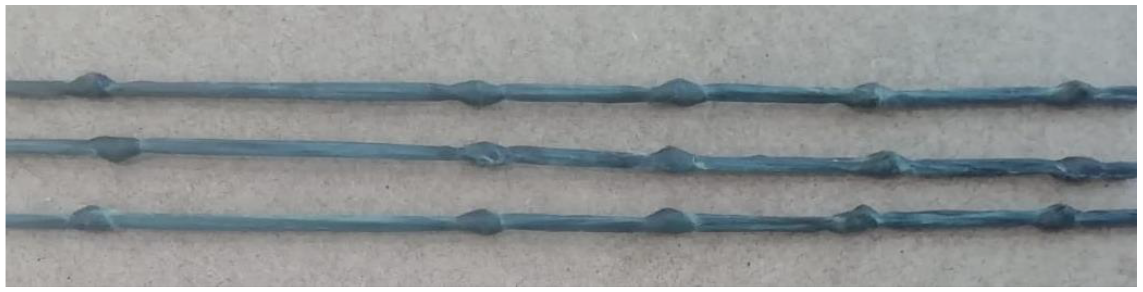
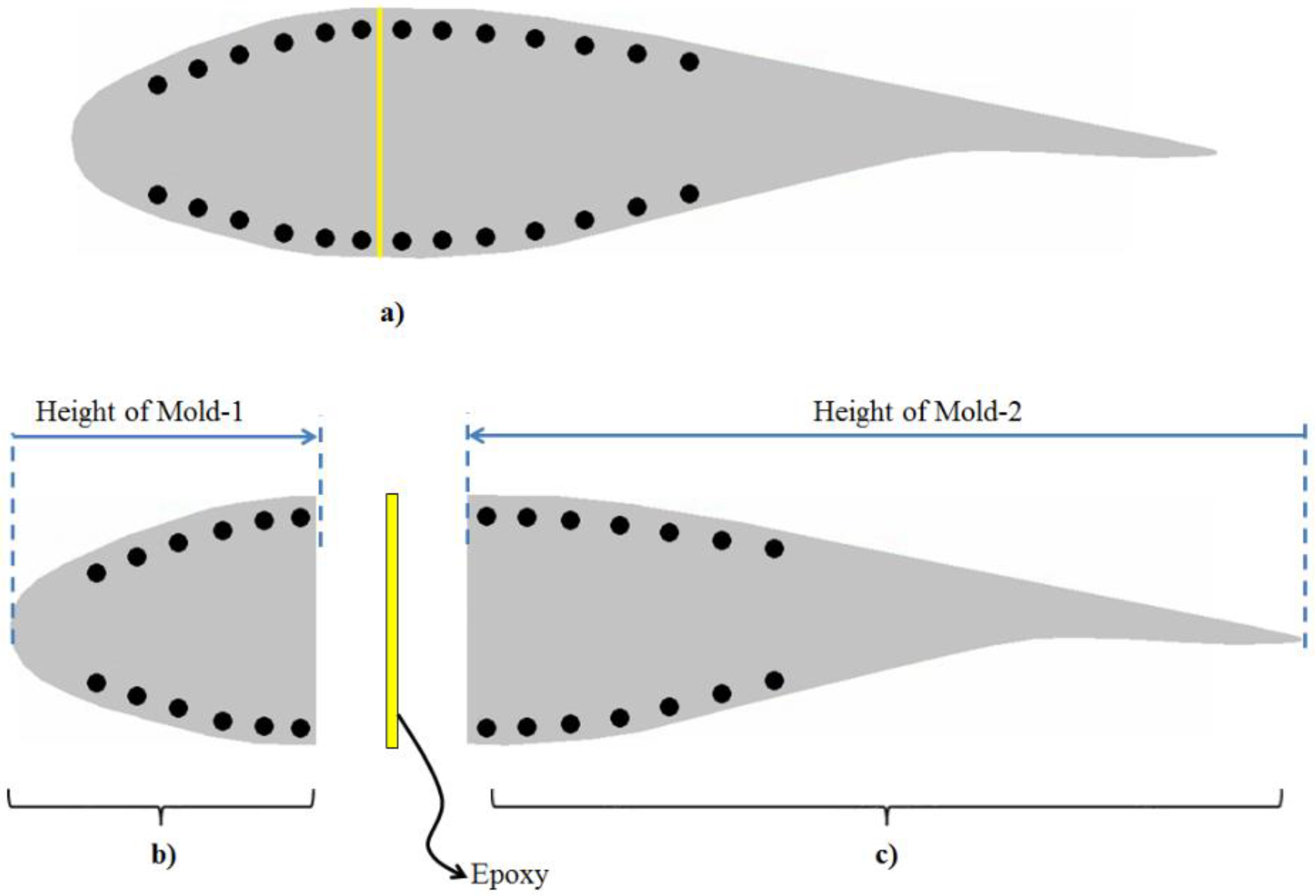
2.1. Manufacturing of the New Generation Blade

In order to minimize delamination type fractures, which are frequently encountered in traditional turbines, new generation blades are inspired by the structure of composite reinforced concrete beams, which are widely used in the construction industry. In this production, continuous carbon-based bars are used instead of reinforcing steel bars in reinforced concrete beams, and recycled low-density polyethylene is also used instead of the concrete material. In addition, as is known, deformations are formed on the steel bars of the reinforced concrete structures in order to increase the interfacial bonding strength between the steel bars and concrete material. In other words, due to the usage of the deformed steel bars, we can ensure that the steel reinforcements do not slide into the concrete material. This important because the reliability of the design calculations of the reinforced concrete beams depends on the fact that the concrete material in the beams works as a whole with the adjacent steel reinforcement without slipping. With this context, in order to produce the new generation blade of this study so that it operates under a similar principle, sliding of the carbon reinforcement within the blade must be minimized. For this reason, knotted structures were arbitrarily formed on each carbon-based bar to be used for the production of the new generation blade. The visuals of these knotted structures are given in Figure 1. Additionally, only this much information will be given in terms of the creation of these knotted structures, which were developed within the company established by one of the authors, since the know-how on this subject is evaluated to be within the scope of trade secrets. As a matter of fact, it is vital to minimize any reduction in the strength capacity of carbon rods during the creation of knotted structures, and the know-how in this regard belongs to the company.
Figure 2 is plotted to represent the locations of the knotted bars within the airfoil of the new generation blade. According to Figure 2, the new generation blade was produced in two separate parts using two different molds. In order to realize the production of these separate parts, two molds with different shapes were first obtained (see Figure 2). Both blade pieces were produced by heating in a furnace after the placement of the knotted carbon bars and recycled polyethylene material in the molds. These pieces were then glued together using a trace amount of epoxy material as shown in Figure 2. It can be emphasized that the amount of epoxy in the new generation blade is negligible when compared with the amount of resin or epoxy used in traditional turbine blades. Additionally, it is thought that this epoxy, which is used a negligible amount, does not have a negative effect on the recycling of new generation blades. Because, as is known from the recycling industry, the materials are never recycled in pure form. Moreover, the new generation blade in this study has already been produced using an impure recycled form of low-density polyethylene (F2–12).

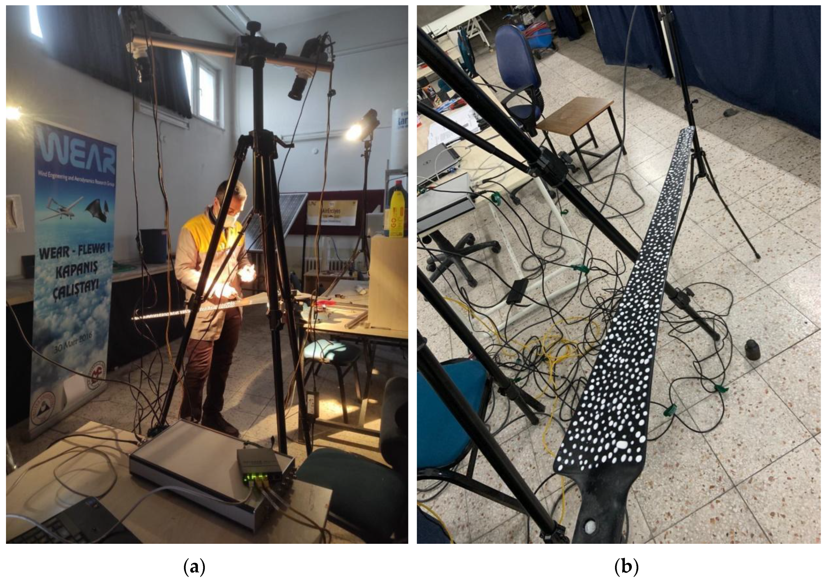
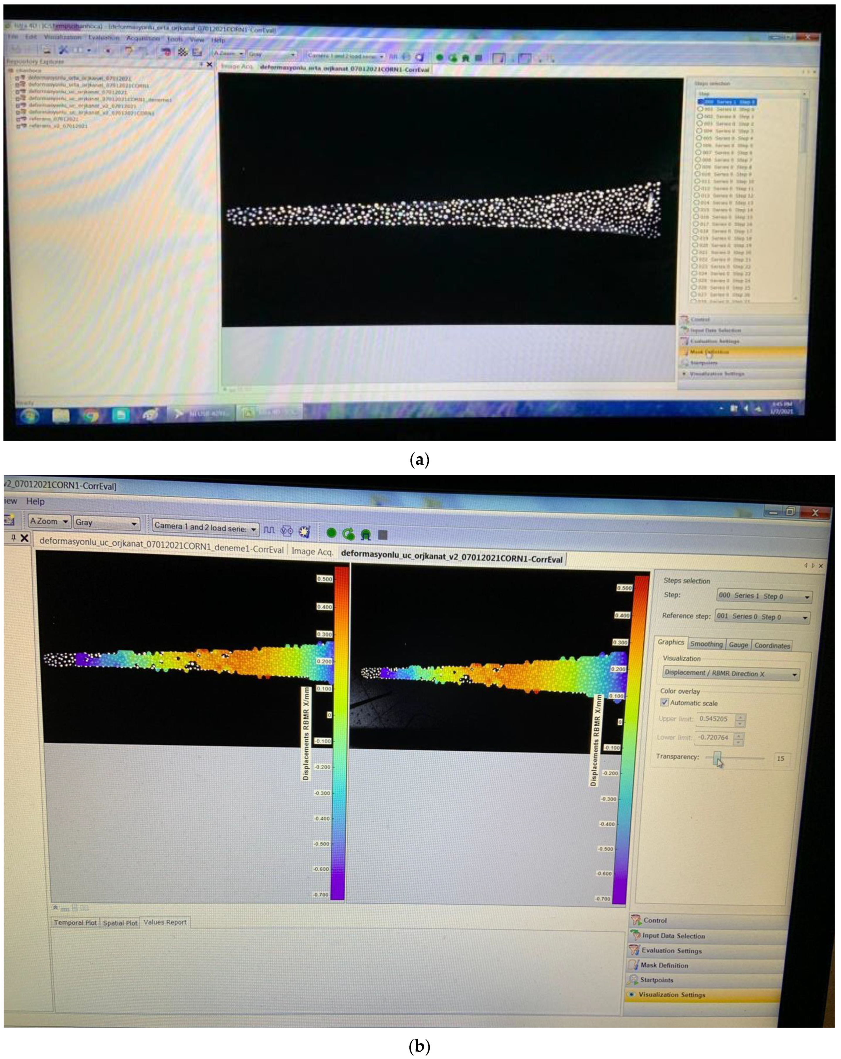
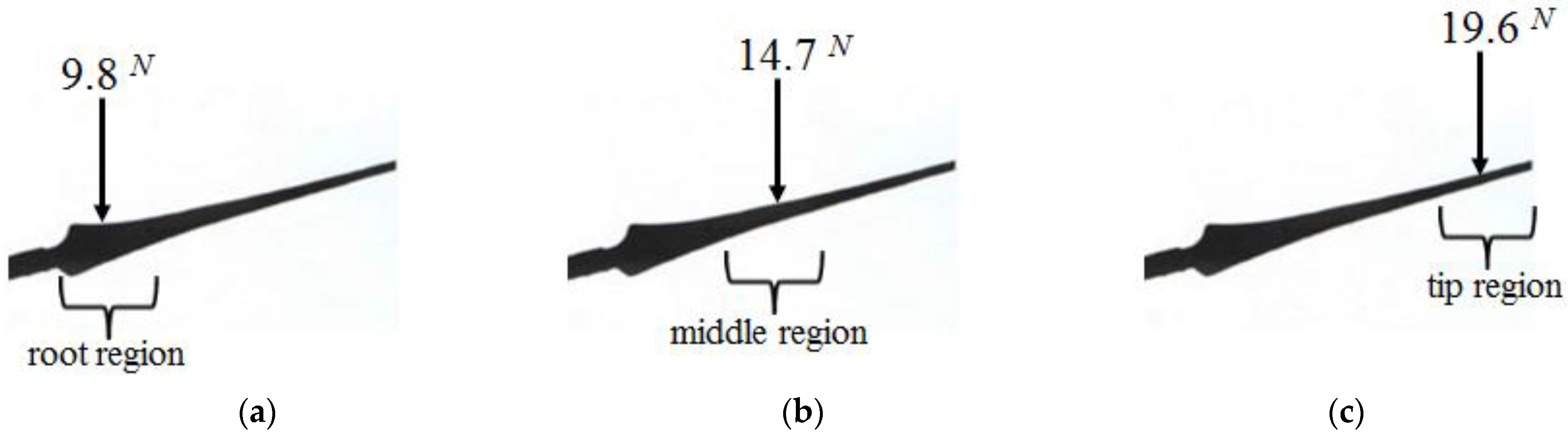
2.2. Digital Image Correlation Method

In this study, a digital image correlation (DIC) system was used to obtain the strength and displacements of both new generation blade and purchased commercial blades under static load. The DIC system captures repetitive images and then calculates the displacements of samples by tracking the deformation of the white dots applied to the surface of the samples using a cross-correlation method [39,40]. The DIC system used in this study includes 2 × 1 megapixel (MP) high speed cameras, 2 spot lamps, Zeiss precision F-Mount 35 mm lens, and ISTRA 4D software with a calibration target. The maximum frame rate of the camera is 1000 frames per second with a resolution of 1280 × 800 pixels. In order to activate the system, first the calibration process is performed. Calibration was performed before the experiment using a square work area of 500 mm × 500 mm. In the calibration process, first, the calibration board was displayed with 2 compact cameras and 2 spot lamps, and the speckled structure was defined in the system by transferring it to the software.
Both of the blades were made ready by being painted as a white dot (pattern) for the application of the DIC system as in Figure 3. The purpose of this process is to obtain deformation and displacement measurements by referring to the white dots of the cameras in the DIC system.
According to Figure 4a, the images of both the purchased commercial blade and the manufactured new generation blade—before being subjected to any load—were taken by using the commercial software of the DIC system. These first images will be used as the reference image for the blades, and according to this reference image, the deformation values of the blades under static load can be calculated. The color changes in the images in Figure 4b indicate the strain values formed on the surface of the blades under loading.
While the strength and displacement of the wind turbine blades are obtained by using the DIC system, the static loads applied on the blades are given in Figure 5. In order to compare the 2-kW small-scale ISTRA BREZEE brand commercial wind turbine blade with the new generation blade which has the same size and profile, the loads shown in Figure 5 are separately applied at the root, middle and tip regions of both blades. Information about the locations of the applied loads is given in Figure 5. While applying these loads, the deformations were measured with the DIC system.

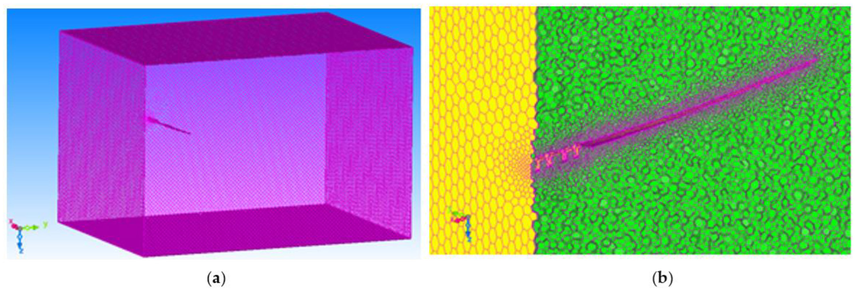
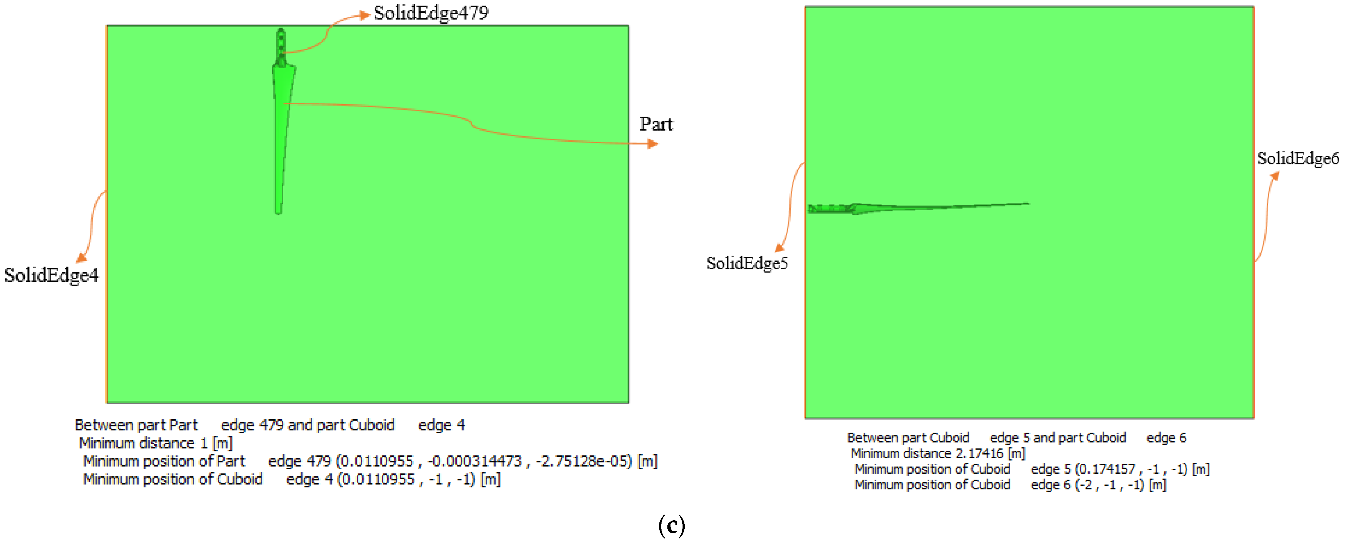
2.3. Finite Element Modeling for the Blades
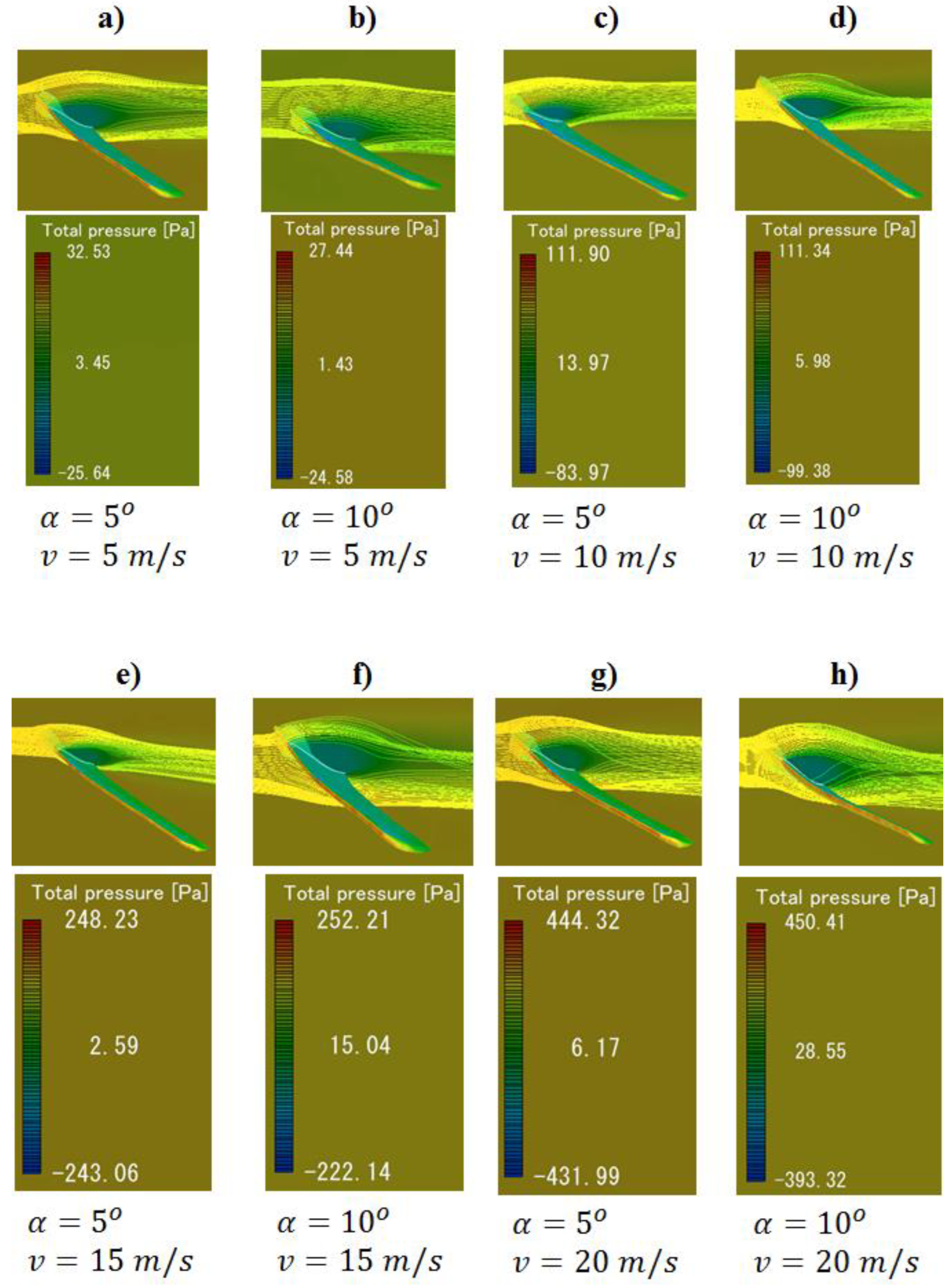
It is important for the energy sector that the new generation blades can be modeled as in the traditional blades. In addition, the heterogeneity of the new generation blades makes their modeling difficult. The modeling of a classical heterogeneous system will require information about several characteristics, which can be obtained from the coupon tests of the different materials in composite structures and also from interfacial bonding tests between these different materials. Then all these obtained mechanical data must be defined during modeling. Instead of obtaining all these data, this study deals with facilitating the modeling of the blade structural system as a whole. In this modeling, ADINA R.D. Inc. commercial engineering simulation software program was used. As mentioned in the tutorial examples of this program, it is possible to combine the mechanical properties of the entire structural system into just one batch of moment–bending curve data by considering the beam element structure as a whole in the finite element method. In other words, the moment–curvature curve shows how the output data of a simple beam structure changes according to the input data when bending, and it briefly illustrates the relationship between input and output. In this respect, by using the moment–curvature data, the behavior of beam structures with a variable cross-sectional area when bending can be modeled as a whole. For this modeling, it is sufficient to model the blades as a cantilever beam element without even defining the cross-sectional areas. The blades are modeled in two dimensions and the displacements in the flapwise testing direction could be calculated by the finite element method. These calculated displacement values will then be compared with the experimental values obtained from the DIC flapwise tests. By the way, to maintain control over the mesh size in the finite element modelling, mesh sizes were increased until consistent displacement output data were obtained. In addition, there is no need to define the mechanical properties of different materials in the finite element model of the blades. The only data needed here is to know the moment–curvature data of both commercial and new generation blades. Experimental data using the DIC system were used to learn these moment–curvature data. In light of these experimental data, the moment–curvature data of the root, middle and tip regions were obtained by using the strain values at the blade surfaces. In other words, the moment–curvature calculation of each region was roughly calculated by using the strain data of the root, middle and tip regions of the turbine blades obtained from the DIC experiments in the formula in Equation (1) [41]. Finally, the bending behavior of composite blades, whether homogeneous or heterogeneous, can be easily modeled using the learned moment–curvature curve.
Curvature = Strain ( blade   thickness ) × ( 0.5 )

2.4. Flow Analyses

In wind turbines, flow energy is converted into mechanical energy, and mechanical energy is converted into electrical energy in the generator. During this transformation, the effect of air as a fluid on the blades and the aerodynamic forces resulting from this action are basically based on pressure distributions. Flow analysis is required to obtain these pressure distributions, and these analyses can be done with CFD software [17,42,43]. In this study, MSC CRADLE, one of the MSC One software products, was used to obtain pressure distributions. In the numerical flow analysis, the flow area was firstly created according to the blade length. The same mesh structure was applied to the blade and the created flow area as seen in Figure 6 in each analysis. The hexagonal network structure formed in the blade and flow area was determined as a total of 922,673 octant (number of elements). In Figure 7, it is seen that while the mesh structure is denser in the blade, it is evenly distributed over the flow area in order to measure the changes in the blade more precisely. The angles of attack (α) were selected as 5° and 10° in the analyses. Pressure distributions were obtained by giving 5 m/s, 10 m/s, 15 m/s and 20 m/s fluid velocities at each angle of attack. The pressure distribution data obtained from the CRADLE program were applied to the blade beam models in order to determine the behavior of the blades under different wind speeds and different angles of attack and also to simulate the structure-fluid interaction.

3. Results and Discussion

The results obtained in this study include (1) the data results of the experimental tests of the blades with the DIC system, (2) the results of the flow analyses, and (3) the behavior of the blades modeled in the finite element method.

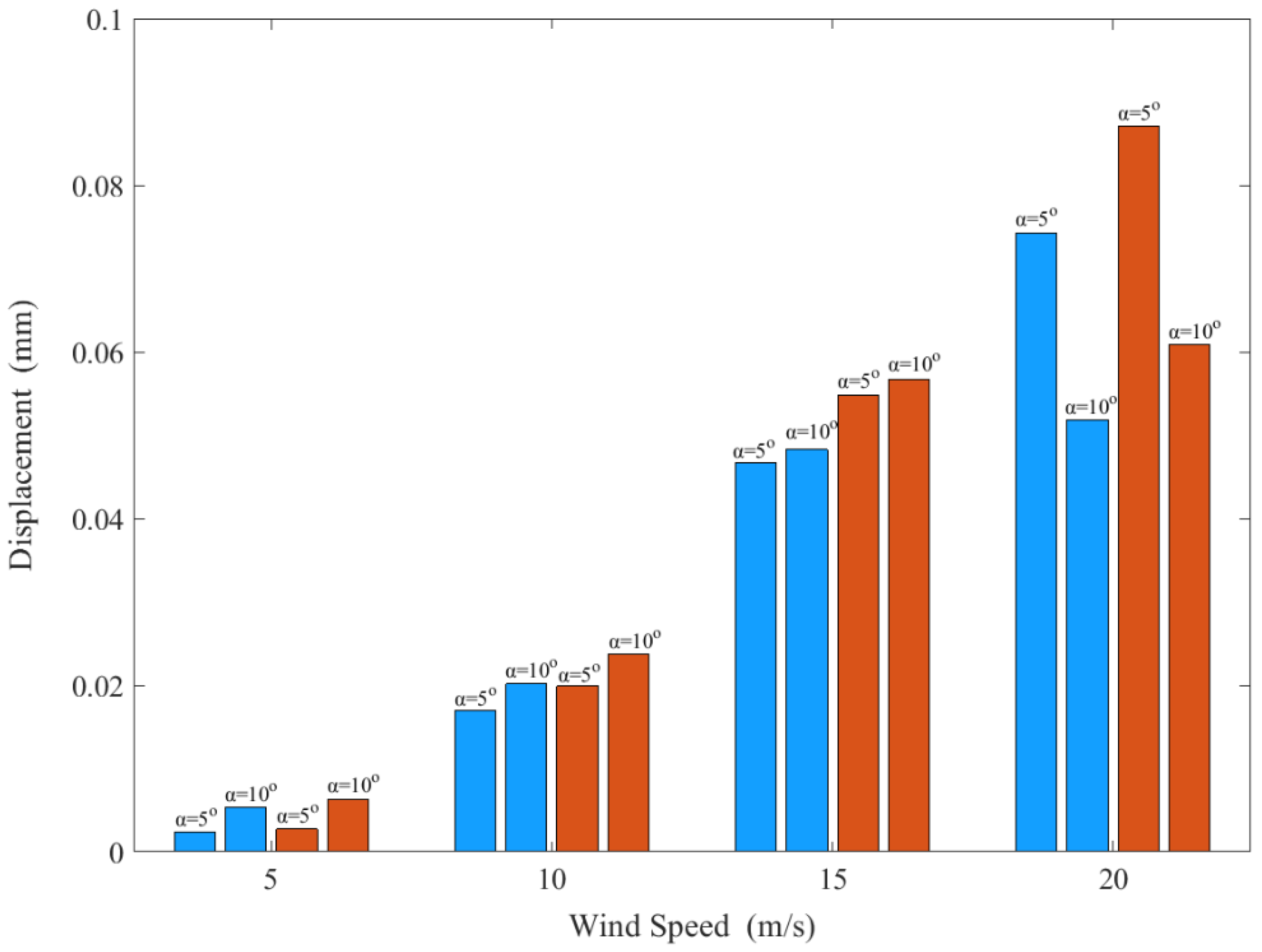
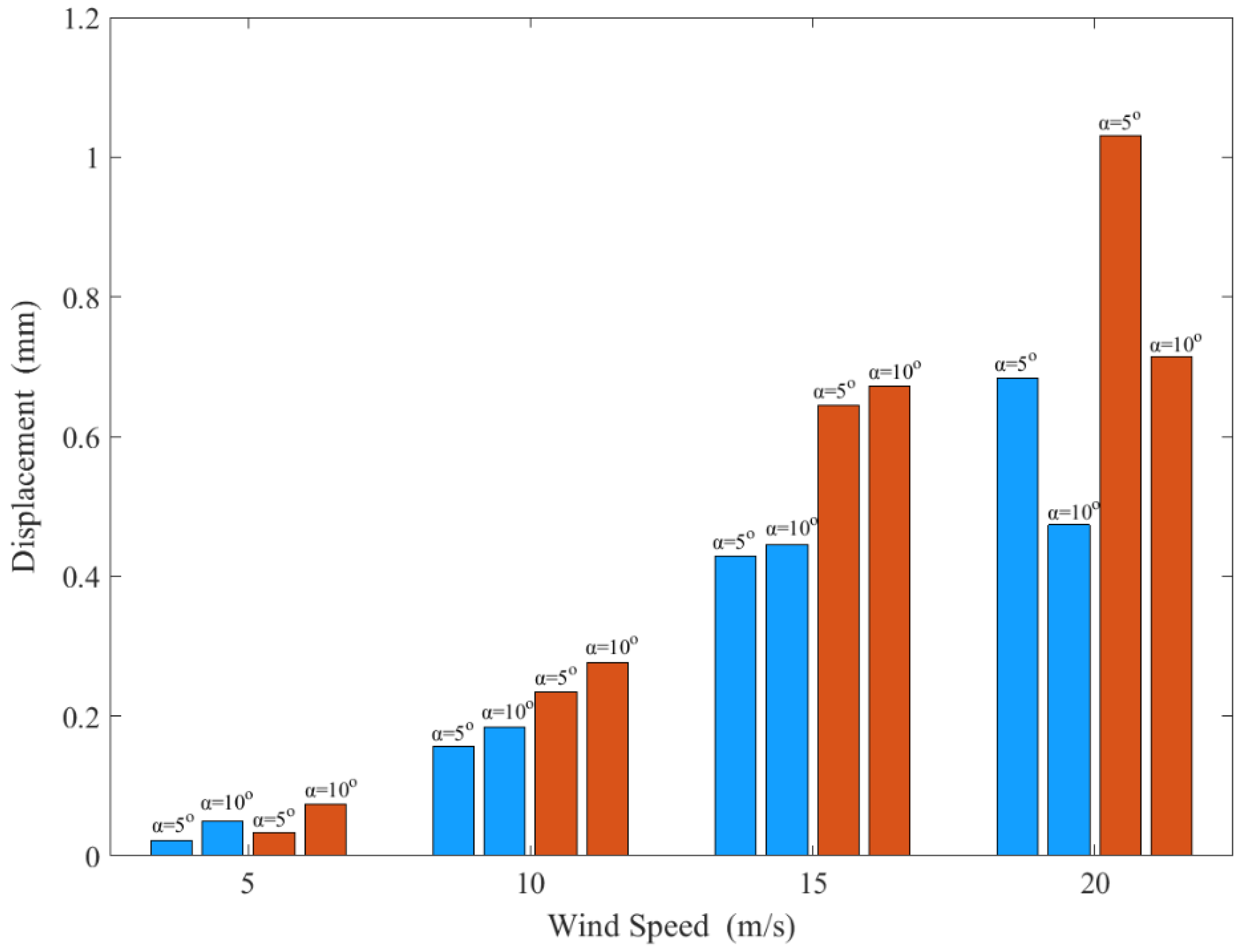
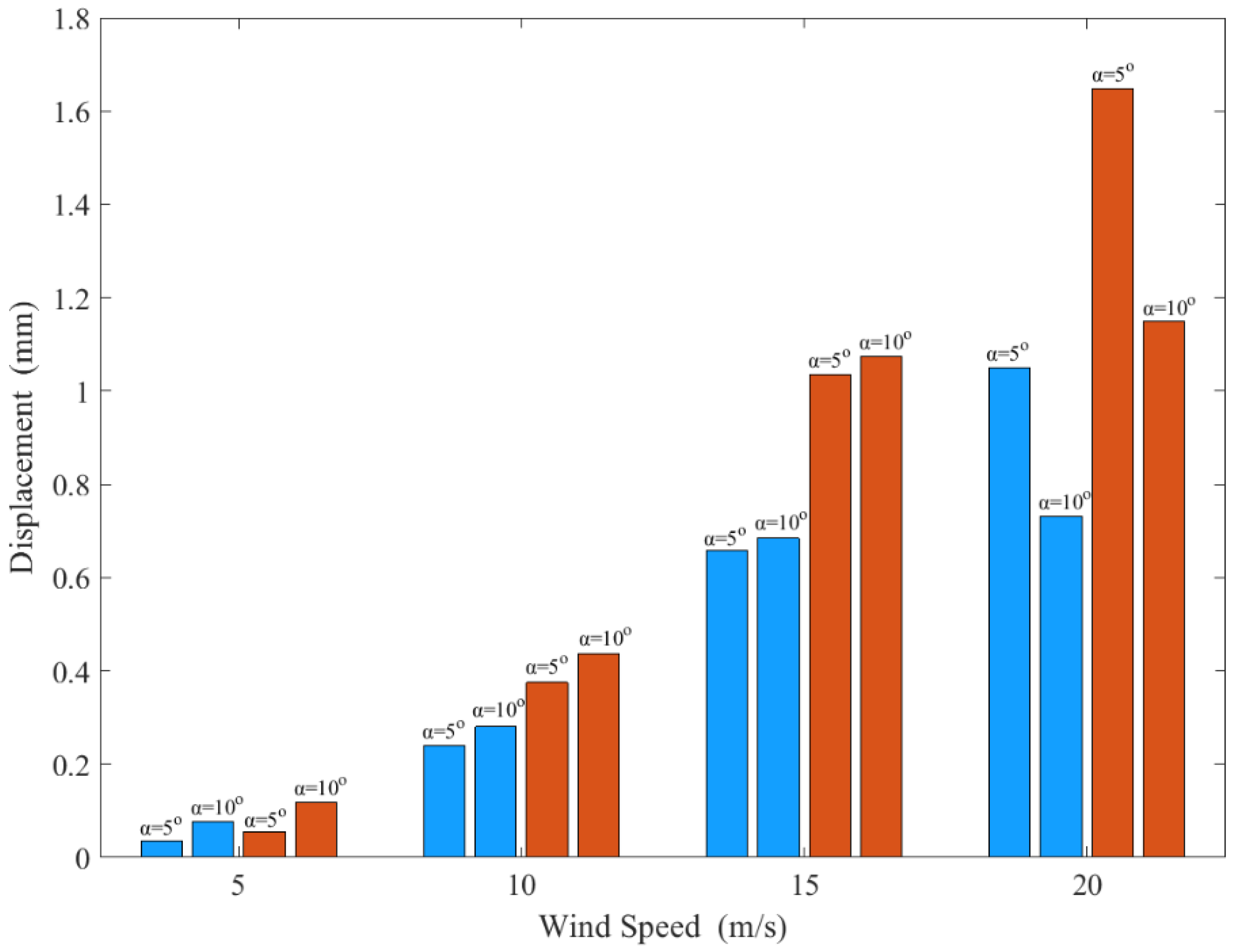
3.1. Experimental Results Obtained from the DIC System

The strengths of both commercial and new generation blades under static load (see Figure 5) were compared using the DIC system. Table 1 has been created to better understand this comparison. In Table 1, the displacement and surface strain values of both the commercial and new generation blades are shown corresponding to each test case. When these displacement and strain values are compared, it is revealed that the new generation blade has higher stiffness than a commercial one. For example, after applying a single load to the tip region of both blades, the displacement values along the longitudinal axis of commercial and new generation blades vary between 5 mm–60 mm and 0.8 mm–30.3 mm, respectively. Since this example shows that the commercial blade makes about two-times more displacement than the new generation blade under the same load, it turns out that the stiffness value (stiffness = force/displacement) of the commercial blade is approximately equal to half of the stiffness of the other blade. In addition, if the strain values formed on the surfaces of the blades are to be compared with each other, the average strain values occurring in the root region of commercial and new generation blades are shown as approximately 0.0070 and 0.0029, respectively (see Table 1). The average strain values in the middle region of commercial and new generation blades are also shown as approximately 0.0147 and 0.0059, respectively. Finally, the average strain values in the tip region of commercial and new generation blades are approximately 0.0247 and 0.0129, respectively.
Table 1 also includes the displacement data for commercial and new generation blades after applying a single load to the middle and root regions. When the single load is applied to the middle region of the blades, the maximum displacements of the commercial and new generation blades are calculated as approximately 14 mm and 11.57 mm, respectively. This shows that the new generation blade again exhibits higher endurance performance. However, this is not the case when a single load is applied to the root zone. In other words, the maximum displacements of commercial and new generation blades were calculated as approximately 0.41 mm and 0.55 mm when the single load was applied to the root regions of the blades. In addition, considering that the displacement values calculated at such low values will be within the margin of error of the DIC system, it would be difficult to claim anything through comparison of the new generation and commercial blades with these data.
When the data in Table 1 are examined, the surface strain distributions that occur when a single load is applied to the middle regions of both blades show that the new generation blade is 77% stiffer than the commercial blade. In addition, the surface strain distributions formed when a single load is applied to the root regions of both blades show that the new generation blade is 43% more rigid than the commercial blade. However, as stated above, the new generation blade displaces more when a single load is applied to the root region of both blades. In this context, it can be thought that there is a mismatch between the displacement data from the DIC system and the stain data. However, it is thought that the main reason for this incompatibility is not related to the DIC system or commercial software, but that a possible fixation problem may have occurred during the testing of the new generation blade under the single load at its root region. In other words, since the strain data are independent of the perfection of the fixation of the blades, it is thought that the displacement data may have been greatly affected by a problem with the fixation of the blade root.
According to Table 1, it can be seen that there is more variation in the different color distributions on the blade surface for the commercial blade. It is thought that the excess in this change is due to the heterogeneity of the internal structure of the new generation blade. In order to further reduce the standard deviation of the strain values on the surface of the new generation blade and also to standardize its production, it is thought that an optimization and design study should be carried out on the number of knotted carbon reinforcements and the distance between these reinforcements.

3.2. Results of Flow Analyses

Figure 7 shows the pressure distributions on the blade as the wind speed increases from 5 m/s to 20 m/s at different angles of attack (5° and 10°). In these distributions, it is seen that the flow separations increase with the increase of the angle of attack. In addition, with the wind speed increase, the total pressure values increased approximately 13.6 times for the angle of attack of 5°; this value is approximately 16.4 for the angle of attack of 10°. While the flow separation leaves the blade surface late in Figure 7a, it is seen in Figure 7e that the flow separation decreases with the effect of the inertia force. It is seen that the flow separation in Figure 7a is later than Figure 7b at the same wind speed. It can be concluded that, with the increase of the angle of attack, the flow is not able to cope with the reverse pressure gradient and viscous forces, and it cannot hold on to the blade surface. The separation of the flow from the blade surface reduces the aerodynamic performance of the blade.
According to the CRADLE analysis given in Table 2, Force-Y expresses the drag force (FD) on the blade, while Force-Z expresses the lift force (FL). When the wind speed value increases from 5 m/s to 20 m/s, it was observed that the lift force increased 15.23 and 15.09 times at the 50° and 10° angles of attack, respectively. It is also seen that the lift force is 0.91% more effective at the angle of attack of 5° than 10°.

3.3. Blade Modeling Results

To recall, the curvatures of the blades were calculated according to Equation (1) by using the blade surface strain values obtained from the DIC tests. Then, these curvature data together with the moment diagram of the blades formed the moment–curvature inputs for the blades in modelling. These DIC tests could be verified by using these inputs in the material definition section in the blade modeling. For this verification, the blade displacement outputs from the models can be compared with the displacement data obtained from the experimental DIC tests (see Table 3). The errors in Table 3 show that the model results generally show a good agreement with the test results. In Table 3, it can be accepted that one of these errors is high. As mentioned before, it is thought that this high error may stem from a problem with the fixation of the new generation blade during one of the DIC tests.
After validating the models with experimental data, the pressure values obtained from the flow analyses at different wind speeds and angles of attack were applied to the root, middle and tip sections of the blades. With these new simulation models, the mechanical behavior of both commercial and new generation blades at different angles of attack and different wind speeds were investigated. The displacement values in the root, middle and tip regions of the wings, which are dependent on these behaviors, are shared in Table 4. In addition, to facilitate the comparison of these displacement values with each other, these values are also discussed in Figure 8, Figure 9 and Figure 10. Figure 8, Figure 9 and Figure 10 show the displacement values in the root, middle and tip regions of both blades, respectively. The “brown” and “blue colors” in these figures represent commercial and new generation blades, respectively.
According to the data in Figure 8, the displacement values of both wings increase at similar rates for both angles of attack (5° and 10°) with increasing wind speed from 5 m/s to 15 m/s. However, the effect of the angle of attack comes to the fore when the wind speed is 20 m/s. Therefore, when the wind speed is 15 m/s or 20 m/s at a 10° angle of attack, the variation of the displacement values of both blades remains small. In addition, when the blue and brown colors in Figure 8 are compared with each other, it is revealed that the displacement values of the root zone of the new generation blade are always calculated lower than the commercial one for each speed and each angle of attack. It is seen that the difference between the displacement values of the new generation and the commercial blades increases with the increase in wind speed.
The data in Figure 9 and Figure 10 also show other displacement distributions compatible with the data in Figure 8. Therefore, according to the data in these figures, it is revealed that the displacement values of the middle and tip regions of the new generation blade are always lower than the commercial blade at different wind speeds and different angles of attack. This also indicates that the stiffness of the new generation blade is higher than the commercial one. Finally, in these figures, as in Figure 8, the difference between the displacement values of the new generation blade and the commercial blade increases with increasing wind speed.

4. Conclusions

The main purpose of this study was to provide the production of an innovative wind turbine blade with a new perspective. This new point of view is to compare the turbine blade structure to the reinforced concrete beam structure, which is frequently used in construction technology. Just as concrete is used as a matrix material in reinforced concrete beams and steel bars are used for reinforcing material, it is also possible to strengthen the recyclable light plastic matrix material in turbine blades with the help of carbon or glass bars. The use of recyclable materials in the production of this turbine blade also makes this new production technique more environmentally friendly. In addition, the fact that the amount of epoxy or resin used in traditional turbine blades is considerably higher than the trace amount of epoxy material used in the production of the new generation blade, emphasizes the importance of this new production.
In order to explain to the energy sector that the new generation turbine blade technology can be functional, it was compared with the commercial turbine blade of the same size and profile. Experimental DIC tests were applied for these comparisons and it can be seen that the new generation blade was stiffer. In addition, a simple modeling approach for both the commercial and the new generation blades is also presented in this study in order to attract the attention of the energy industry. In addition, the models of both blades were used with flow analysis and their behaviors at different speeds and different angles of attack were determined. All these findings demonstrate that the new generation blade has the possibility to exhibit sufficient strength in the field.

Author Contributions

Conceptualization, C.Ç. and M.S.G.; Methodology, C.Ç. and M.S.G.; Software, C.Ç., A.E. and M.S.G.; Validation, C.Ç. and M.S.G.; Formal analysis, C.Ç. and M.S.G.; Investigation, C.Ç., A.E. and M.S.G.; Writing—original draft, C.Ç., A.E. and M.S.G.; Writing—review & editing, C.Ç. and M.S.G.; Visualization, A.E. and M.S.G.; Supervision, C.Ç. and M.S.G.; Funding acquisition, C.Ç. and M.S.G. All authors have read and agreed to the published version of the manuscript.

Funding

This work was supported by R&D Innovation Program of KOSGEB (Small and Medium Enterprises Development Organization of Turkey), which is established in the Ministry of Industry and Technology of Republic of Turkey (grant number 1774102). Additionally, the authors would like to thank the Scientific and Technological Research Council of Turkey (TÜBİTAK) under the 2210-D and Erciyes University Scientific Research Projects (BAP) Unit-Turkey under (FKA-2020-10255).

Data Availability Statement

Not applicable.

Conflicts of Interest

The authors proclaim that they have no known conflicting financial interest or personal associations that could have appeared to affect the work stated in this paper.

References

  1. Ergüner, A.; Özkan, R.; Koca, K.; Genç, M.S. Improvement of Mechanical Behaviour of Wind Turbine Blade Using Nanofluid-Graphene and/or Glass Fiber in Epoxy Resin. J. Therm. Eng. 2019, 5, 93–99. [Google Scholar]
  2. Genç, M.S.; Gökçek, M. Evaluation of wind characteristics and energy potential in Kayseri, Turkey. J. Energy Eng. 2010, 135, 33–43. [Google Scholar] [CrossRef]
  3. Genç, M.S. Economic analysis of large-scale wind energy conversion systems in central anatolian Turkey. In Clean Energy Systems and Experiences; IntechOpen: Rijeka, Croatia, 2010; pp. 131–154. [Google Scholar]
  4. Genç, M.S. Economic viability of water pumping systems supplied by wind energy conversion and diesel generator systems in North Central Anatolia, Turkey. J. Energy Eng. 2011, 137, 21–35. [Google Scholar] [CrossRef]
  5. Genç, M.S.; Karipoğlu, F.; Koca, K.; Azgın, Ş.T. Suitable site selection for offshore wind farms in Turkey’s seas: GIS-MCDM based approach. Earth Sci. Inform. 2022, 14, 1213–1225. [Google Scholar] [CrossRef]
  6. Karipoğlu, F.; Genç, M.S.; Koca, K. Determination of the most appropriate site selection of wind power plants based Geographic Information System and Multi-Criteria Decision-Making approach in Develi, Turkey. Int. J. Sustain. Energy Plan. Manag. 2021, 30. [Google Scholar] [CrossRef]
  7. Akarsu, B.; Genç, M.S. Optimization of electricity and hydrogen production with hybrid renewable energy systems. Fuel 2022, 324, 124465. [Google Scholar] [CrossRef]
  8. Kara, M.; Ercan, Y.; Yumuşak, R.; Cürebal, A.; Eren, T. Yenilenebilir Hibrit Enerji Santrali Uygulamasında Tesis Yer Seçimi. Uluslararası Mühendislik Araştırma Ve Geliştirme Derg. 2022, 14, 208–227. [Google Scholar] [CrossRef]
  9. Türkiye Rüzgar Enerjisi Birliği, 2021 Faaliyet Raporu. Available online: https://tureb.com.tr//haber/2021-faaliyet-raporu/276 (accessed on 25 January 2023).
  10. İzmir Kalkınma Ajansı, Rüzgâr Enerjisi Sektörü Ve İzmir Denizüstü Rüzgâr Enerjisi Yol Haritası, Temmuz 2021. Available online: https://izka.org.tr/wp-content/uploads/2021/08/ruzgar_enerjisi_sekto%CC%88ru%CC%88-izmir_denizustu_ruzgar_enerjisi_yol-haritasi-2.pdf (accessed on 4 March 2022).
  11. Cooperman, A.; Eberle, A.; Lantz, E. Wind turbine blade material in the United States: Quantities, costs, and end-of-life options, Resources. Conserv. Recycl. 2021, 168, 105439. [Google Scholar] [CrossRef]
  12. Liu, P.; Barlow, C.Y. Wind turbine blade waste in 2050. Waste Manag. 2017, 62, 229–240. [Google Scholar] [CrossRef]
  13. Andersen, P.D.; Bonou, A.; Beauson, J.; Brøndsted, P. Recycling of Wind Turbines, DTU International Energy Report 2014: Wind Energy—Drivers and Barriers for Higher Shares of Wind in the Global Power Generation Mix; Technical University of Denmark: Lyngby, Denmark, 2014; pp. 91–97. [Google Scholar]
  14. İzmir Kalkınma Ajansı, İzmir İli Rüzgâr Türbini Kanadı Geri Dönüşüm Tesisi, Ön Fizibilite Raporu, Haziran 2021. Available online: https://www.yatirimadestek.gov.tr/pdf/assets/upload/fizibiliteler/izmir-ili-ruzgar-turbini-kanadi-geri-donusum-tesisi-on-fizibilite-raporu2022.pdf (accessed on 27 January 2023).
  15. Genç, M.S.; Açıkel, H.H.; Akpolat, M.T.; Özkan, G.; Karasu, İ. Acoustic control of flow over NACA 2415 aerofoil at low Reynolds numbers. J. Aerosp. Eng. 2016, 29, 04016045. [Google Scholar] [CrossRef]
  16. Açıkel, H.H.; Genç, M.S. Flow control with perpendicular acoustic forcing on NACA 2415 aerofoil at low Reynolds numbers. Proc. IMechE. Part G- J. Aerosp. Eng. 2016, 230, 2447–2462. [Google Scholar] [CrossRef]
  17. Genç, M.S.; Lock, G.; Kaynak, Ü. An experimental and computational study of low Re number transitional flows over an aerofoil with leading edge slat. In Proceedings of the 26th Congress of ICAS and 8th AIAA ATIO, AIAA-8877, Anchorage, AK, USA, 14–19 September 2008. [Google Scholar]
  18. Açıkel, H.H.; Genç, M.S. Control of laminar separation bubble over wind turbine airfoil using partial flexibility on suction surface. Energy 2018, 165, 176–190. [Google Scholar] [CrossRef]
  19. Genç, M.S.; Koca, K.; Demir, H.; Açıkel, H.H. Traditional and new types of passive flow control techniques to pave the way for high maneuverability and low structural weight for UAVs and MAVs. Auton. Veh. 2020, 131–160. [Google Scholar] [CrossRef] [Green Version]
  20. Genç, M.S.; Açıkel, H.H.; Koca, K. Effect of partial flexibility over both upper and lower surfaces to flow over wind turbine airfoil. Energy Convers. Manag. 2020, 219, 113042. [Google Scholar] [CrossRef]
  21. Koca, K.; Genç, M.S.; Bayır, E.; Soğuksu, F.K. Experimental study of the wind turbine airfoil with the local flexibility at different locations for more energy output. Energy 2022, 239, 121887. [Google Scholar] [CrossRef]
  22. Blasques, J.P.; Bitsche, R.D.; Fedorov, V.; Lazarov, B.S. Accuracy of an efficient framework for structural analysis of wind turbine blades. Wind Energy 2016, 19, 1603–1621. [Google Scholar] [CrossRef] [Green Version]
  23. Tüfekci, M.; Genel, Ö.E.; Tatar, A.; Tüfekci, E. Dynamic Analysis of Composite Wind Turbine Blades as Beams: An Analytical and Numerical Study. Vibration 2021, 4, 1–15. [Google Scholar] [CrossRef]
  24. Meng, H.; Jin, D.; Li, L.; Liu, Y. Analytical and numerical study on centrifugal stiffening effect for large rotating wind turbine blade based on NREL 5 MW and WindPACT 1.5 MW models. Renew. Energy 2022, 183, 321–329. [Google Scholar] [CrossRef]
  25. Algolfat, A.; Wang, W.; Albarbar, A. Study of Centrifugal Stiffening on the Free Vibrations and Dynamic Response of Offshore Wind Turbine Blades. Energies 2022, 15, 6120. [Google Scholar] [CrossRef]
  26. Thai, L.M.; Luat, D.T.; Ke, T.V. Finite element modeling for static bending analysis of rotating two-layer FGM beams with shear connectors resting on imperfect elastic foundations. J. Aerosp. Eng. 2023, in press. [Google Scholar] [CrossRef]
  27. Phung, V.M.; Ta, D.T.; Tran, V.K. Static Bending Analysis of Symmetrical Three-Layer FGM Beam With Shear Connectors Under Static Load. J. Sci. Tech. 2021, 15. [Google Scholar] [CrossRef]
  28. Phung, M.V.; Nguyen, D.T.; Doan, L.T.; Van Duong, T. Numerical Investigation on Static Bending and Free Vibration Responses of Two-Layer Variable Thickness Plates with Shear Connectors. Iran. J. Sci. Technol. Trans. Mech. Eng. 2022, 46, 1047–1065. [Google Scholar] [CrossRef]
  29. Ozsoy, N.; Ozsoy, M.; Mimaroglu, A. Mechanical Properties of Chopped Carbon Fiber Reinforced Epoxy Composites, Special Issue of the 2nd International Conference on Computational and Experimental Science and Engineering; Sakarya University: Serdivan, Turkey, 2016; Volume 130. [Google Scholar]
  30. Siddharta; Kuldeep, G. Mechanical And Abrasive Wear Characterization Of Bidirectional And Chopped E-Glass Fiber Reinforced Composite Materials. Mater. Des. 2012, 35, 467–479. [Google Scholar] [CrossRef]
  31. Barton, D.C.; Soden, P.D. Short-Term In-Plane Stiffness And Strength Properties Of CSM-Reinforced Polyester Laminate. Composites 1982, 13, 66–78. [Google Scholar] [CrossRef]
  32. Hancox, N.L.; Mayer, R.M. Design Data For Reinforced Plastics—A Guide For Engineers And Designers; Chapman & Hall: London, UK, 1994. [Google Scholar]
  33. Johnson, A.F. Engineering Design Properties of GRP; British Plastics Federation: London, UK, 1979. [Google Scholar]
  34. Janeliukstis, R.; Chen, X. Review Of Digital Image Correlation Application To Large-Scale Composite Structure Testing. Compos. Struct. 2021, 271, 114143. [Google Scholar] [CrossRef]
  35. Winstroth, J.; Schoen, L.; Ernst, B.; Seume, J.R. Wind Turbine Rotor Blade Monitoring Using Digital Image Correlation: A Comparison To Aeroelastic Simulations Of A Multi-Megawatt Wind Turbine. J. Phys. Conf. Ser. 2014, 524, 012064. [Google Scholar] [CrossRef] [Green Version]
  36. Wu, R.; Zhang, D.; Yu, Q.; Jiang, Y.; Arola, D. Health Monitoring Of Wind Turbine Blades In Operation Using Three-Dimensional Digital Image Correlation. Mech. Syst. Signal Process. 2019, 130, 470–483. [Google Scholar] [CrossRef]
  37. Mastrodicasa, D.; Lorenzo, E.D.; Manzato, S.; Peeters, B.; Guillaume, P. Full-Field Modal Analysis by Using Digital Image Correlation Technique, Rotating Machinery. Opt. Methods Scanning LDV Methods 2022, 6, 105–112. [Google Scholar]
  38. Khadka, A.; Afshar, A.; Zadeh, M.; Baqersad, J. Strain Monitoring Of Wind Turbines Using a Semi-Autonomous Drone. Wind. Eng. 2022, 46, 296–307. [Google Scholar] [CrossRef]
  39. Genç, M.S. Unsteady aerodynamics and flow-induced vibrations of a low aspect ratio rectangular membrane wing with excess length. Exp. Therm. Fluid Sci. 2013, 44, 749–759. [Google Scholar] [CrossRef]
  40. Genç, M.S.; Demir, H.; Özden, M.; Bodur, T.M. Experimental analysis of fluid-structure interaction in flexible wings at low Reynolds number flows. Aircr. Eng. Aerosp. Technol. 2021, 93, 1060–1075. [Google Scholar] [CrossRef]
  41. Beer, F.-P.; Johnston, E.-R.; Dewolf, J.-T.; Mazurek, D.-F. Mechanics of Materials, 7th ed.; McGraw-Hill Education: New York, NY, USA, 2015. [Google Scholar]
  42. Karasu, İ.; Özden, M.; Genç, M.S. Performance assessment of transition models for three-dimensional flow over NACA4412 wings at low Reynolds numbers. J. Fluids Eng. 2018, 140, 121102. [Google Scholar] [CrossRef]
  43. Demir, H.; Özden, M.; Genç, M.S.; Çağdaş, M. Numerical Investigation of Flow on NACA4412 Aerofoil with Different Aspect Ratios. In EPJ Web of Conferences; EDP Sciences: Ulysses, France, 2016; Volume 114. [Google Scholar]
Figure 1. Knotted carbon-based bars used in the production of the new generation blade.
Energies 16 01961 g001
Figure 2. A representative display for the new generation blade. (a) Airfoil after combining two separate parts, (b) representative cross-sectional area of the part coming out of the first mold, (c) representative cross-sectional area of the part coming out of the second mold.
Energies 16 01961 g002
Figure 3. Making the necessary preparations for the experimental analysis of the blades in the DIC system, (a) painting work required for the DIC system, (b) blade surface after painting.
Energies 16 01961 g003
Figure 4. Application of the DIC method on a selected blade (a) reference image (b) strain distributions on the blades.
Energies 16 01961 g004
Figure 5. Representative images of the loads of (a) 9.8 N, (b) 14.7 N, (c) 19.6 N applied on the blades when using the DIC system.
Energies 16 01961 g005
Figure 6. The mesh structure (a) the flow domain (b) the meshed blade and (c) length scale of the meshed blades.
Energies 16 01961 g006aEnergies 16 01961 g006b
Figure 7. Pressure distribution on varying wind speeds and angles of attack: (a) α = 5° v = 5 m/s (b) α = 10° v = 5 m/s (c) α = 5° v = 10 m/s (d) α = 10° v = 10 m/s (e) α = 5° v = 15 m/s (f) α = 10° v = 15 m/s (g) α = 5° v = 20 m/s (h) α = 10° v = 20 m/s.
Energies 16 01961 g007
Figure 8. Modelling displacements of both blades at the root region. Red and blue colors are for commercial and new generation blades, respectively.
Energies 16 01961 g008
Figure 9. Modelling displacements of both blades at the middle region. Red and blue colors are for commercial and new generation blades, respectively.
Energies 16 01961 g009
Figure 10. Modelling displacements of both blades at the tip region. Red and blue colors are for commercial and new generation blades, respectively.
Energies 16 01961 g010
Table 1. Displacements and surface strain values of both blades corresponding to the DIC tests.
Blade TypeApplication of DIC TestsDisplacements of the Blades Corresponding to the DIC TestsBlade Surface Strain Values Corresponding to the DIC Tests
Blade Root RegionBlade Middle RegionBlade Tip Region
Commercial BladeEnergies 16 01961 i001Energies 16 01961 i002Energies 16 01961 i003Energies 16 01961 i004Energies 16 01961 i005
New Generation BladeEnergies 16 01961 i006Energies 16 01961 i007Energies 16 01961 i008Energies 16 01961 i009Energies 16 01961 i010
Commercial BladeEnergies 16 01961 i011Energies 16 01961 i012Energies 16 01961 i013Energies 16 01961 i014Energies 16 01961 i015
New Generation BladeEnergies 16 01961 i016Energies 16 01961 i017Energies 16 01961 i018Energies 16 01961 i019Energies 16 01961 i020
Commercial BladeEnergies 16 01961 i021Energies 16 01961 i022Energies 16 01961 i023Energies 16 01961 i024Energies 16 01961 i025
New Generation BladeEnergies 16 01961 i026Energies 16 01961 i027Energies 16 01961 i028Energies 16 01961 i029Energies 16 01961 i030
Table 2. Lift and drag forces at varying speeds and angles of attack.
Wind Speed (m/s)Force TypeAngle of Attack
10°
5Force-Y (N)0.28090.3534740
Force-Z (N)−0.19985−0.3127885
10Force-Y (N)1.1180191.388722
Force-Z (N)−0.86685−1.2039
15Force-Y (N)2.4597893.097886
Force-Z (N)−1.719546−2.6772
20Force-Y (N)4.3512315.480113
Force-Z (N)−3.042711−4.72061
Table 3. Displacements of both blades at the tip region corresponding to DIC tests and finite element modellings.
Blade TypeDisplacements from DIC TestsDisplacements from ModelingsError (%)
Load at Root Region (mm)Load at Middle Region (mm)Load at Tip Region (mm)Load at Root Region (mm)Load at Middle Region (mm)Load at Tip Region (mm)Load at Root Region (mm)Load at Middle Region (mm)Load at Tip Region (mm)
Commercial blade0.4114.060.00.375813.265657.7843854
New generation blade 0.5511.630.30.319110.864732.51914267
Table 4. Modeling results for commercial and new generation blades for varying wind speeds and different angles of attack.
Blade Root RegionBlade Middle RegionBlade Tip Region
α = 5 o α = 10 o α = 5 o α = 10 o α = 5 o α = 10 o
Commercial Blade v = 5   m / s 0.002710.006340.033290.074300.055360.11812
v = 10   m / s 0.019920.023650.234920.275850.374920.43756
v = 15   m / s 0.054820.056720.645250.672171.034561.07430
v = 20   m / s 0.087160.060921.030660.713741.648341.14930
New Generation Blade v = 5   m / s 0.002310.005400.021850.049400.034600.07550
v = 10   m / s 0.016960.020140.155970.183610.239100.28010
v = 15   m / s 0.046660.048290.428260.445860.658800.68433
v = 20   m / s 0.074210.051860.683830.473791.050030.73111
Disclaimer/Publisher’s Note: The statements, opinions and data contained in all publications are solely those of the individual author(s) and contributor(s) and not of MDPI and/or the editor(s). MDPI and/or the editor(s) disclaim responsibility for any injury to people or property resulting from any ideas, methods, instructions or products referred to in the content.

