
Performance Prediction of Plate-Finned Tube Heat Exchangers for Refrigeration: A Review on Modeling and Optimization Methods


Abstract
:1. Introduction
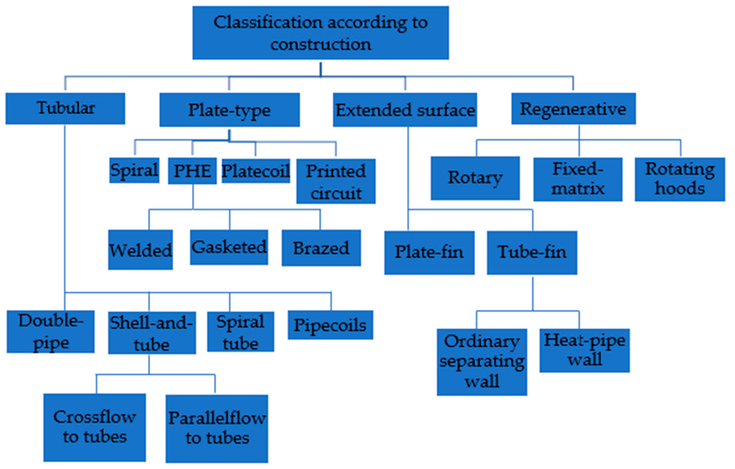
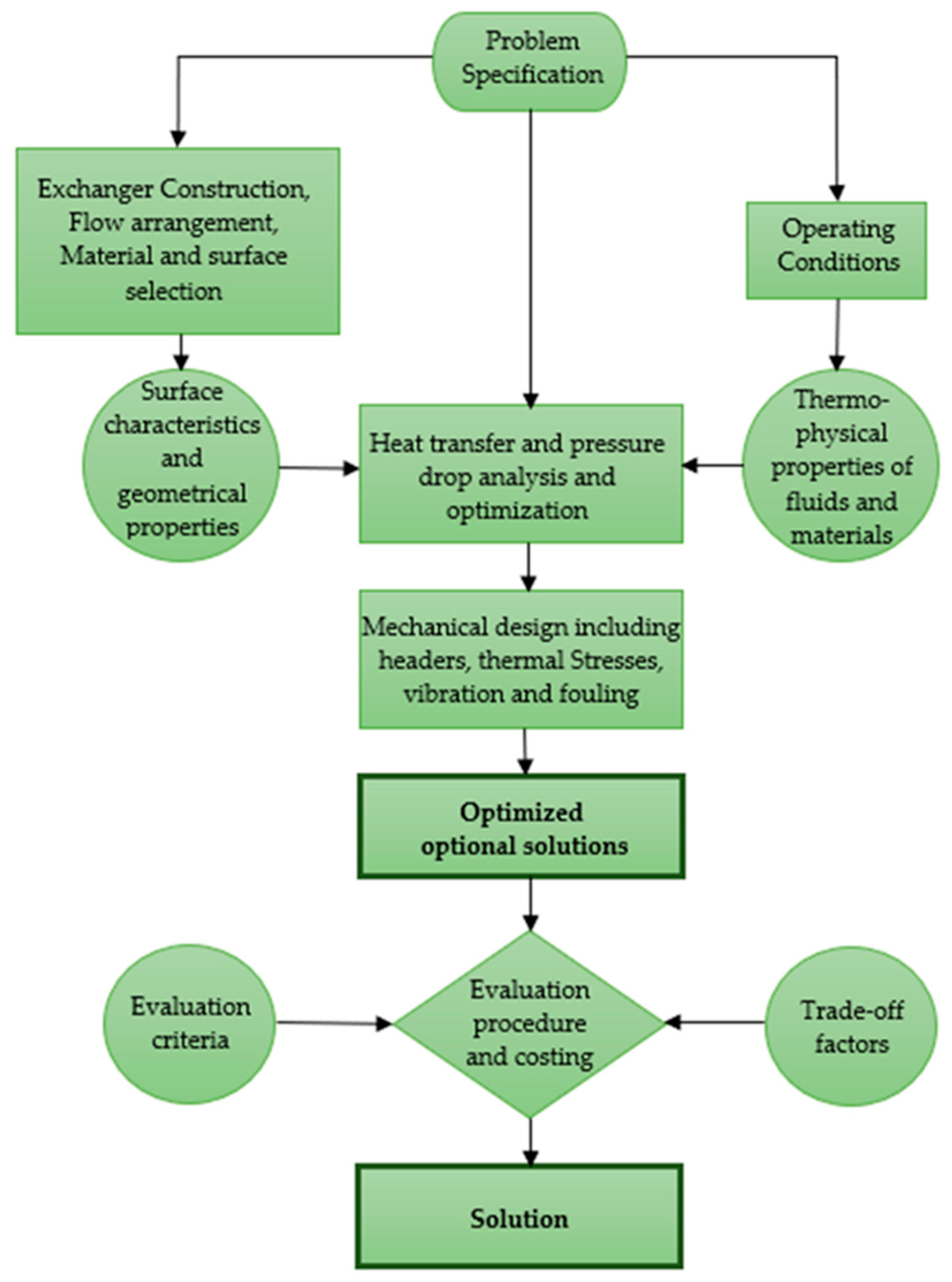
2. Heat Exchanger Design Procedure
3. Heat Exchanger Modelling Methods
3.1. Large Scale Models: Experimental Correlations for Fluid Properties Calculation
3.2. Large Scale Models: Analytical and Semi-Analytical Studies
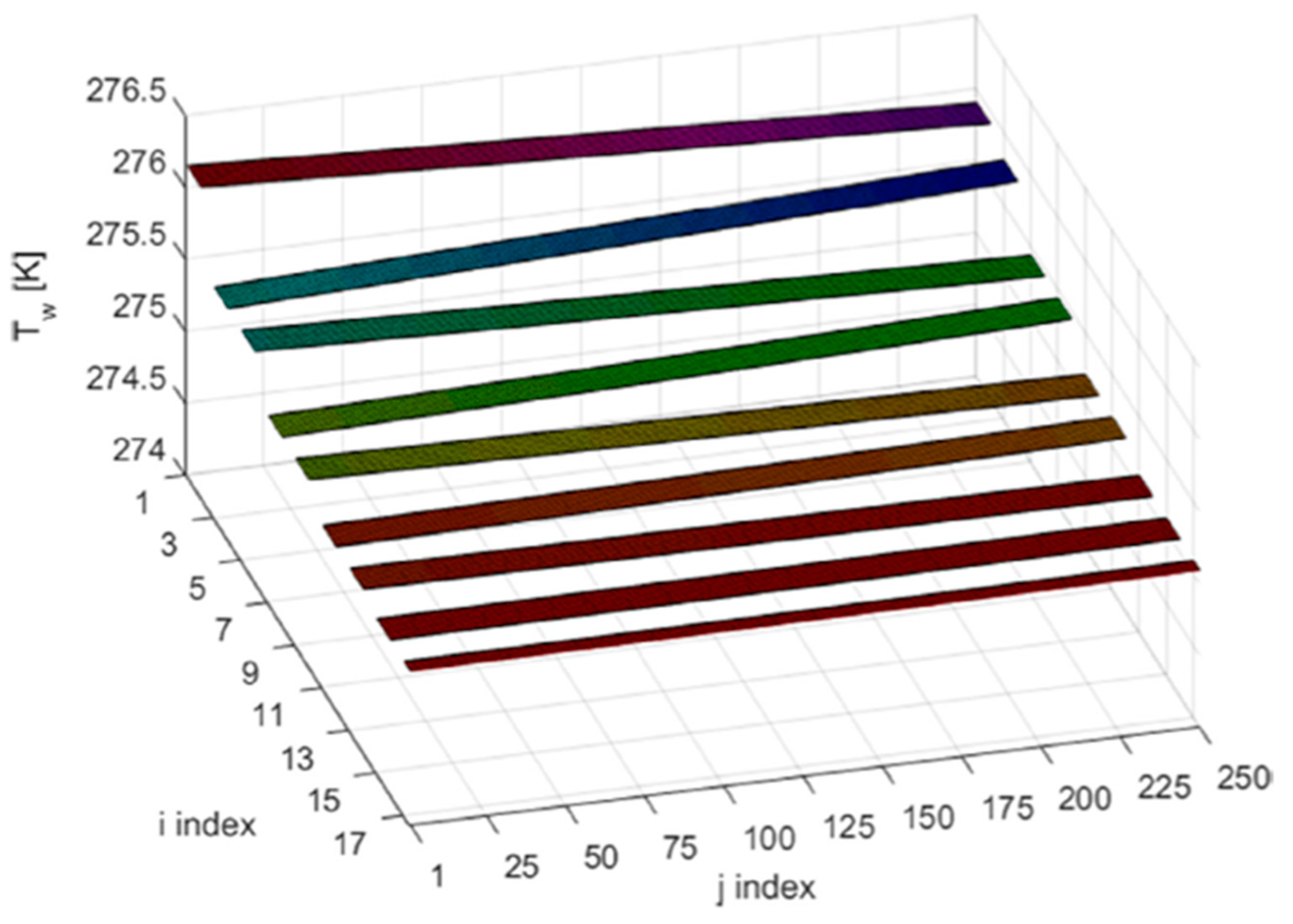
3.3. Small-Scale and Dynamic Models
3.4. Multi-Scale Models
4. Heat Exchanger Optimization Methods
5. Conclusions, Future Trends and Recommendations
- In the last couple of years, research has focused above all on the study of the fluid-dynamic and thermal characteristics of the exchangers through the use of CFD techniques [68,69,70,71,72,73]. Several experimental tests were also carried out for the same purpose [22,23,24,25,26,27,28], but in order to save time and resources, it is recommended that research goes even deeper into cost-saving methods—without loss of accuracy—such as multi-scale models for the prediction of performance.
- Greater accuracy in predicting pressure drops would be appreciable in future research. Most of the analytical models analyzed here showed a good agreement of the simulated data with the experimental tests in terms of heat capacity, but failed to predict pressure losses as effectively (deviation was found between 15% and 30%).
- A good design is often penalized by unexpected working conditions, such as non-uniform air distribution at the inlet or refrigerant maldistribution, due to blocked or partially clogged tubes, which significantly degrade performance. Some studies were performed in the past to predict the exchanger behavior in real operating conditions, but further investigation needs to be carried out in the future.
- Future research studies should also include the superheat region for evaporators and subcooling for condensers as these operating zones often occur in practice.
- Performance prediction of HXs under frosting conditions is very complex as it is a dynamic phenomenon that leads to a drastic worsening of performance. In order to develop more accurate frosting analytical models, it is recommended that future studies will focus on this research area.
- A research path that has been developing in recent years concerns the modeling of heat exchangers with improved and compound fin geometries, such as fins with diamond or circular perforations and vortex generators as well as new tube shapes (rhombic, hexagon, etc.). Further developments in this research area are desirable since the results obtained in terms of performance improvement are encouraging.
- Recently, very interesting experimental studies [27,28] showed that the performance of a reversible heat pump can be enhanced by means of different circuitry arrangements for the exchanger whether it is used as an evaporator or condenser. These studies can be the basis to make progress in developing new computational and optimization models for heat exchangers with reversely-variable circuitry.
Author Contributions
Funding
Data Availability Statement
Conflicts of Interest
Nomenclature
| D | tube diameter (m) | Abbreviations | |
| Dh | hydraulic diameter (m) | ANN | artificial neural network |
| f | friction factor | CCD | central composite design method |
| J | Colburn factor | CFD | computational fluid dynamics |
| L | tube length (m) | CHX | compact heat exchanger |
| NR | number of tube rows | COP | coefficient of performance |
| Nu | Nusselt number | DFO | derivate-free optimization |
| average Nusselt number | FTHX | finned tube heat exchanger | |
| Nuz | Nusselt number by Zukauskas correlation | GA | genetic algorithm |
| PF | fin pitch (m) | HTC | heat transfer coefficient |
| PL | longitudinal pitch (m) | HX | heat exchanger |
| Pr | Prandtl number | IGA | improved genetic algorithm |
| PT | transverse pitch (m) | IPGA | integer permutation-based genetic algorithm |
| Re | Reynolds number | KBCM | knowledge-based computational module |
| Sh | Sherwood number | KBEM | knowledge-based evolution method |
| Greek symbols | NTU | number of transfer units | |
| ε | heat transfer effectiveness | PBCM | permutation-based computational module |
| RSM | response surface method | ||
References
- Bergman, A.A.; Incropera, F.P. Fundamentals of Heat and Mass Transfer; John Wiley & Sons: Hoboken, NJ, USA, 2011. [Google Scholar]
- Rohsenow, W.M.; Hartnett, J.P.; Cho, Y.I. Handbook of Heat Transfer, 3rd ed.; McGraw-Hill: New York, NY, USA, 1998. [Google Scholar]
- Tahseen, T.M.; Ishak, M.; Rahman, M.M. An overview on thermal and fluid flow characteristics in a plain plate finned and un-finned tube banks heat exchanger. Renew. Sustain. Energy Rev. 2015, 43, 363–380. [Google Scholar] [CrossRef] [Green Version]
- Basavarajappa, S.; Manavendra, G.; Prakash, S.B. A review on performance study of finned tube heat exchanger. J. Phys. Conf. Ser. 2020, 1473, 012030. [Google Scholar] [CrossRef]
- Kakac, S.; Liu, H. Heat Exchangers: Selection, Rating and Thermal Design, 2nd ed.; CRC Press: Boca Raton, FL, USA, 2002. [Google Scholar]
- Hesselgreaves, J.E.; Law, R.; Reay, D. Compact Heat Exchangers: Selection, Design and Operation, 2nd ed.; Butterworth-Heinemann: Oxford, UK, 2016. [Google Scholar]
- Zohuri, B. Compact Heat Exchangers, 1st ed.; Springer: Cham, Switzerland, 2017. [Google Scholar]
- Klemes, J.J.; Arsenyeva, O.; Kapustenko, P.; Tovazhnyanskyy, L. Compact Heat Exchangers for Energy Transfer Intensification: Low Grade Heat and Fouling Mitigation, 1st ed.; CRC Press: Boca Raton, FL, USA, 2015. [Google Scholar]
- Wang, C.-C.; Hwang, Y.-M.; Lin, Y.-T. Empirical correlations for heat transfer and flow friction characteristics of herringbone wavy fin-and-tube heat exchangers. Int. J. Refrig. 2002, 25, 673–680. [Google Scholar] [CrossRef]
- Shah, R.K.; Sekulic, D.P. Fundamentals of Heat Exchanger Design; John Wiley & Sons: Hoboken, NJ, USA, 2003. [Google Scholar]
- Cain, J.W. Mathematical Models in the Sciences. In Molecular Life Sciences; Bell, E., Ed.; Springer: New York, NY, USA, 2014; pp. 1–6. [Google Scholar]
- Colburn, A.P. A method of correlating forced convection heat-transfer data and a comparison with fluid friction. Int. J. Heat Mass Transf. 1964, 7, 1359–1384. [Google Scholar] [CrossRef]
- Rosman, E.; Carajilescov, P.; Saboya, F. Performance of one-and two-row tube and plate fin heat exchangers. J. Heat Transf. 1984, 106, 627–632. [Google Scholar] [CrossRef]
- Dittus, F.; Boelter, L. Heat transfer in automobile radiators of the tubular type. Int. Commun. Heat Mass Transf. 1933, 12, 3–22. [Google Scholar] [CrossRef]
- Merker, G. Heat transfer and pressure drop on the shell-side of tube-banks having oval-shaped tubes. Int. J. Heat Mass Transf. 1986, 29, 1903–1909. [Google Scholar] [CrossRef]
- Wang, C.-C.; Lee, W.-S.; Sheu, W.-J. Airside performance of staggered tube bundle having shallow tube rows. Chem. Eng. Commun. 2001, 187, 129–147. [Google Scholar] [CrossRef]
- Žukauskas, A. Heat Transfer from Tubes in Crossflow. Adv. Heat Transf. 1972, 8, 93–160. [Google Scholar]
- Kim, Y.; Kim, Y. Heat transfer characteristics of flat plate finned-tube heat exchangers with large fin pitch. Int. J. Refrig. 2005, 28, 851–858. [Google Scholar] [CrossRef]
- Khan, M.G.; Fartaj, A.; Ting, D.S.-K. Study of cross-flow cooling and heating of air via an elliptical tube array. ASHRAE Trans. 2005, 111, 423–433. [Google Scholar]
- Paeng, J.; Kim, K.; Yoon, Y. Experimental measurement and numerical computation of the air side convective heat transfer coefficients in a plate fin-tube heat exchanger. J. Mech. Sci. Technol. 2009, 23, 536–543. [Google Scholar] [CrossRef]
- Taler, D. Experimental determination of correlations for average heat transfer coefficients in heat exchangers on both fluid sides. Heat Mass Transf. 2013, 49, 1125–1139. [Google Scholar] [CrossRef] [Green Version]
- Okbaz, A.; Pınarbaşı, A.; Olcay, A.B. Experimental investigation of effect of different tube row-numbers, fin pitches and operating conditions on thermal and hydraulic performances of louvered and wavy finned heat exchangers. Int. J. Therm. Sci. 2020, 151, 106256. [Google Scholar] [CrossRef]
- Bozkula, G.; Demir, H. Experimental investigation of heat transfer and pressure drop of fin and tube heat exchanger under dry and wet conditions. Int. J. Therm. Sci. 2022, 177, 107580. [Google Scholar] [CrossRef]
- Wu, W.; Luo, J.; Li, D.; Feng, X.; Tang, L.; Fang, Z.; Zheng, Z. Experimental Investigation of Heat Transfer Performance of a Finned-Tube Heat Exchanger under Frosting Conditions. Sustain. Cities Soc. 2022, 80, 103752. [Google Scholar] [CrossRef]
- Che, M.; Elbel, S. Experimental quantification of air-side row-by-row heat transfer coefficients on fin-and-tube heat exchangers. Int. J. Refrig. 2021, 131, 657–665. [Google Scholar] [CrossRef]
- Matos, R.S.; Vargas, J.V.C.; Rossetim, M.A.; Pereira, M.V.A.; Pitz, D.B.; Ordonez, J.C. Performance comparison of tube and plate-fin circular and elliptic heat exchangers for HVAC-R systems. Appl. Therm. Eng. 2021, 184, 116288. [Google Scholar] [CrossRef]
- Sim, J.; Lee, H.; Jeong, J.H. Optimal design of variable-path heat exchanger for energy efficiency improvement of air-source heat pump system. Appl. Energy 2021, 290, 116741. [Google Scholar] [CrossRef]
- Wang, F.; Zhao, R.; Ma, C.; Huang, D.; Qu, Z. Reversely-variable circuitry for finned-tube heat exchanger in air source heat pump to enhance its overall energy performance. Int. J. Refrig. 2022, 142, 48–57. [Google Scholar] [CrossRef]
- Kays, W.M.; London, A.L. Compact Heat Exchangers, 3rd ed.; McGraw-Hill: New York, NY, USA, 1984. [Google Scholar]
- Browne, M.W.; Bansal, P.K. An elemental NTU-e model for vapour-compression liquid chillers. Int. J. Refrig. 2001, 24, 612–627. [Google Scholar] [CrossRef]
- Browne, M.W.; Bansal, P.K. Challenges in modeling vapor–compression liquid chillers. ASHRAE Trans. 1998, 104, 474–486. [Google Scholar]
- Corberan, J.M.; Fernandez de Cordoba, P.; Ortuno, S.; Ferri, V.; Setaro, T.; Boccardi, G. Modelling of tube and fin coils working as evaporator or condenser. In Proceedings of the 3rd European Thermal Sciences Conference, Heidelberg, Germany, 10–13 September 2000. [Google Scholar]
- Corberán, J.M.; García, M. Modelling of plate finned tube evaporators and condensers working with R134a. Int. J. Refrig. 1998, 21, 273–284. [Google Scholar] [CrossRef]
- Jiang, H.; Aute, V.; Radermacher, R. CoilDesigner: A general-purpose simulation and design tool for air-to-refrigerant heat exchangers. Int. J. Refrig. 2006, 29, 601–610. [Google Scholar] [CrossRef]
- McQuiston, F. Heat, mass and momentum transfer data for five plate-fin-tube heat transfer surfaces. ASHRAE Trans. 1978, 84, 266–293. [Google Scholar]
- Tarrad, A.H.; Al-Nadawi, A.K. Modelling of finned-tube using pure and zeotropic blend refrigerants. In Proceedings of the ATINER’S Conference, Athens, Greece, 17–20 December 2015. [Google Scholar]
- Joppolo, C.M.; Molinaroli, L.; Pasini, A. Numerical analysis of the influence of circuit arrangement on a fin-and-tube condenser performance. Case Stud. Therm. Eng. 2015, 6, 136–146. [Google Scholar] [CrossRef] [Green Version]
- Tong, L.; Li, H.; Wang, L.; Sun, X.; Xie, Y. The effect of evaporator operating parameters on the flow patterns inside horizontal pipes. J. Therm. Sci. 2011, 20, 324–331. [Google Scholar] [CrossRef]
- Domanski, P.A. Finned-tube evaporator model with a visual interface. In Proceedings of the International Congress of Refrigeration 20th. IIR/IIF, Sydney, Australia, 19–24 September 1999. [Google Scholar]
- Domanski, P.A. Simulation of an evaporator with non-uniform one-dimensional air distribution. ASHRAE Trans. 1991, 97, 793–802. [Google Scholar]
- Bensafi, A.; Borg, S.; Parent, D. CYRANO: A computational model for the detailed design of plate-fin-and-tube heat exchangers using pure and mixed refrigerants. Int. J. Refrig. 1997, 20, 218–228. [Google Scholar] [CrossRef]
- Liang, S.Y.; Wong, T.N.; Nathan, G.K. Numerical and experimental studies of refrigerant circuitry of evaporator coils. Int. J. Refrig. 2001, 24, 823–833. [Google Scholar] [CrossRef]
- Ding, X.; Cai, W.; Jia, L.; Wen, C. Evaporator modeling-A hybrid approach. Appl. Energy 2009, 86, 81–88. [Google Scholar] [CrossRef]
- Singh, V.; Aute, V.; Radermacher, R. Numerical approach for modeling air-to-refrigerant fin-and-tube heat exchanger with tube-to-tube heat transfer. Int. J. Refrig. 2008, 31, 1414–1425. [Google Scholar] [CrossRef]
- Oliet, C.; Perez-Segarra, C.D.; Danov, S.; Oliva, A. Numerical simulation of dehumidifying fin-and-tube heat exchangers: Modeling strategies and experimental comparisons. In Proceedings of the International Refrigeration and Air Conditioning Conference, West Lafayette, IN, USA, 16–19 July 2002. [Google Scholar]
- Liu, J.; Wei, W.; Ding, G.; Zhang, C.; Fukaya, M.; Wang, K.; Inagaki, T. A general steady state mathematical model for fin-and-tube heat exchanger based on graph theory. Int. J. Refrig. 2004, 27, 965–973. [Google Scholar] [CrossRef]
- Niederer, D.H. Frosting and defrosting effects on coil heat transfer. ASHRAE Trans. 1986, 92, 467–473. [Google Scholar]
- Kondepudi, S.N.; O’Neal, D.L. The effects of frost growth on extended surface heat exchanger performance: A review. ASHRAE Trans. 1987, 93, 258–277. [Google Scholar]
- Kondepudi, S.N.; O’Neal, D.L. Effect of frost growth on the performance of louvered finned tube heat exchangers. Int. J. Refrig. 1989, 12, 151–158. [Google Scholar] [CrossRef]
- Kondepudi, S.N.; O’Neal, D.L. The effects of different fin configurations on the performance of finned-tube heat exchangers under frosting conditions. ASHRAE Trans. 1990, 96, 439–444. [Google Scholar]
- Seker, D.; Karatas, H.; Egrican, N. Frost formation on fin- and- tube heat exchangers. Part II—Experimental investigation of frost formation on fin- and- tube heat exchangers. Int. J. Refrig. 2004, 27, 375–377. [Google Scholar] [CrossRef]
- Kim, K.; Kim, D.R.; Lee, K.-S. Local frosting behavior of a plated-fin and tube heat exchanger according to the refrigerant flow direction and surface treatment. Int. J. Heat Mass Transf. 2013, 64, 751–758. [Google Scholar] [CrossRef]
- Yan, W.-M.; Li, H.-Y.; Wu, Y.-J.; Lin, J.-Y.; Chang, W.-R. Performance of finned tube heat exchangers operating under frosting conditions. Int. J. Heat Mass Transf. 2003, 46, 871–877. [Google Scholar] [CrossRef]
- Zhang, L.; Jiang, Y.; Dong, J.; Yao, Y.; Deng, S. An experimental study on the effects of frosting conditions on frost distribution and growth on finned tube heat exchangers. Int. J. Heat Mass Transf. 2019, 128, 748–761. [Google Scholar] [CrossRef]
- Reichl, C.; Sandström, C.; Hochwallner, F.; Linhardt, F.; Popovac, M.; Emhofer, J. Frosting in heat pump evaporators part A: Experimental investigation. Appl. Therm. Eng. 2021, 199, 117487. [Google Scholar] [CrossRef]
- Lee, K.S.; Kim, W.S.; Lee, T.H. A one dimensional model for frost formation on a cold flat surface. Int. J. Heat Mass Transf. 1997, 40, 4359–4365. [Google Scholar] [CrossRef]
- Tso, C.P.; Cheng, Y.C.; Lai, A.C.K. Dynamic behavior of a direct expansion evaporator under frosting condition, part I. Distributed model. Int. J. Refrig. 2006, 29, 611–623. [Google Scholar] [CrossRef]
- Tso, C.P.; Cheng, Y.C.; Lai, A.C.K. An improved model for predicting performance of finned tube heat exchanger under frosting conditions, with frost thickness variation along fin. Appl. Therm. Eng. 2006, 26, 111–120. [Google Scholar] [CrossRef]
- Yang, D.K.; Lee, K.S.; Song, S. Modeling for predicting frosting behavior of a fin tube heat exchanger. Int. J. Heat Mass Transf. 2006, 49, 1478–1479. [Google Scholar] [CrossRef]
- Padhmanabhan, S.K.; Fisher, D.; Cremaschi, L.; Moallem, E. Modeling non uniform frost growth on a fin and tube heat exchanger. Int. J. Refrig. 2011, 34, 2018–2030. [Google Scholar] [CrossRef]
- Ye, H.Y.; Lee, K.S. Performance prediction of a fin and tube heat exchanger considering air flow reduction due to the frost accumulation. Int. J. Heat Mass Transf. 2013, 67, 225–233. [Google Scholar] [CrossRef]
- Silva, D.L.; Hermes, C.J.L.; Melo, C. First principles modelling of frost accumulation on fan supplied tube fin evaporators. Appl. Therm. Eng. 2011, 31, 2616–2621. [Google Scholar] [CrossRef]
- Chen, H.; Thomas, L.; Besant, R.W. Fan supplied heat exchanger fin performance under frosting conditions. Int. J. Refrig. 2003, 26, 140–149. [Google Scholar] [CrossRef]
- Hwang, J.; Cho, K. Numerical prediction of frost properties and performance of fin-tube heat exchanger with plain fin under frosting. Int. J. Refrig. 2014, 46, 59–68. [Google Scholar] [CrossRef]
- Bhuiyan, A.A.; Islam, A.S. CFD analysis of different fin-and-tube heat exchangers. J. Mech. Eng. 2011, 62, 237–249. [Google Scholar]
- Wang, C.C.; Chang, Y.J.; Hsieh, Y.C.; Lin, Y.T. Sensible heat and friction characteristics of plate fin-and-tube heat exchangers having plane fins. Int. J. Refrig. 1996, 19, 223–230. [Google Scholar] [CrossRef]
- Wang, C.C.; Fu, W.L.; Chang, C.T. Heat transfer and friction characteristics of typical wavy fin-and-tube heat exchangers. Exp. Therm. Fluid Sci. 1997, 14, 174–186. [Google Scholar] [CrossRef]
- Lee, Y.T.; Chien, L.H.; He, J.; Wen, C.-Y.; Yang, A.S. Air side performance characterization of wavy Fin-and-tube heat exchangers having elliptic tubes with large waffle heights. Appl. Therm. Eng. 2022, 217, 119220. [Google Scholar] [CrossRef]
- Rauber, W.K.; Silva, U.F.; Vaz, M.; Alves, M.V.C.; Zdanski, P.S.B. Investigation of the effects of fin perforations on the thermal-hydraulic performance of Plate-Finned heat exchangers. Int. J. Heat Mass Transf. 2022, 187, 122561. [Google Scholar] [CrossRef]
- Li, Y.; Qian, Z.; Wang, Q. Numerical investigation of thermohydraulic performance on wake region in finned tube heat exchanger with section-streamlined tube. Case Stud. Therm. Eng. 2022, 33, 101898. [Google Scholar] [CrossRef]
- Lindqvist, K.; Skaugen, G.; Meyer, O.H.H. Plate fin-and-tube heat exchanger computational fluid dynamics model. Appl. Therm. Eng. 2021, 189, 116669. [Google Scholar] [CrossRef]
- Taler, D.; Taler, J.; Trojan, M. Thermal calculations of plate–fin–and-tube heat exchangers with different heat transfer coefficients on each tube row. Energy 2020, 203, 117806. [Google Scholar] [CrossRef]
- Taler, D.; Taler, J.; Wrona, K. Transient response of a plate-fin-and-tube heat exchanger considering different heat transfer coefficients in individual tube rows. Energy 2020, 195, 117023. [Google Scholar] [CrossRef]
- Zhao, B.; Bi, H.; Wang, H.; Zhou, Y. Experimental and numerical investigation on frosting of finned-tube heat exchanger considering droplet impingement. Appl. Therm. Eng. 2022, 216, 119134. [Google Scholar] [CrossRef]
- Popovac, M.; Emhofer, J.; Reichl, C.H. Frosting in a heat pump evaporator part B: Numerical analysis. Appl. Therm. Eng. 2021, 199, 117488. [Google Scholar] [CrossRef]
- Zdravitsch, F.; Fletcher, C.; Behnia, M. Laminar and turbulent heat transfer predictions in tube banks in cross flow. In Proceedings of the International Conference on Fluid and Thermal Energy Conversion, Denpasar, Indonesia, 12–15 December 1994. [Google Scholar]
- Romero-Méndez, R.; Sen, M.; Yang, K.; McClain, R. Effect of fin spacing on convection in a plate fin and tube heat exchanger. Int. J. Heat Mass Transf. 2000, 43, 39–51. [Google Scholar] [CrossRef]
- Tutar, M.; Akkoca, A.; Oztekin, S.; Turkey, B.A. A numerical study of heat transfer and fluid flow in a plate fin-and-tube heat exchanger. Asme-Publications-Pvp 2001, 431, 77–84. [Google Scholar]
- Zhang, W.J.; Zhang, C.L. A generalized moving-boundary model for transient simulation of dry-expansion evaporators under larger disturbances. Int. J. Refrig. 2006, 29, 1119–1127. [Google Scholar] [CrossRef]
- Willatzen, M.; Pettit, N.B.O.L.; Ploug-Sørensen, L. A general dynamic simulation model for evaporators and condensers in refrigeration. Part I: Moving-boundary formulation of two-phase flows with heat exchange. Int. J. Refrig. 1998, 21, 398–403. [Google Scholar] [CrossRef]
- Pettit, N.B.O.L.; Willatzen, M.; Ploug-Sørensen, L. A general dynamic simulation model for evaporators and condensers in refrigeration. Part II: Simulation and control of an evaporator. Int. J. Refrig. 1998, 21, 404–414. [Google Scholar] [CrossRef]
- Shao, L.L.; Zhang, C.L. Logic unconstrained multi-zone evaporator and condenser models. Int. J. Refrig. 2007, 30, 926–931. [Google Scholar] [CrossRef]
- Illán-Gómez, F.; García-Cascales, J.R.; Molina-Valverde, R.; Velasco, F.J.S. A discretization method for the characterization of a plate heat exchanger working as evaporator during transient conditions. Int. J. Therm. Sci. 2023, 184, 107998. [Google Scholar] [CrossRef]
- Starace, G.; Fiorentino, M.; Longo, M.P.; Carluccio, E. A hybrid method for the cross flow compact heat exchangers design. Appl. Therm. Eng. 2017, 111, 1129–1142. [Google Scholar] [CrossRef]
- Carluccio, E.; Starace, G.; Ficarella, A.; Laforgia, D. Numerical analysis of a cross-flow compact heat exchanger for vehicle applications. Appl. Therm. Eng. 2005, 25, 1995–2013. [Google Scholar] [CrossRef]
- Fiorentino, M.; Starace, G. The design of countercurrent evaporative condensers with the hybrid method. Appl. Therm. Eng. 2018, 130, 889–898. [Google Scholar] [CrossRef]
- Starace, G.; Fiorentino, M.; Meleleo, B.; Risolo, C. The hybrid method applied to the plate-finned tube evaporator geometry. Int. J. Refrig. 2018, 88, 67–77. [Google Scholar] [CrossRef]
- Starace, G.; Macchitella, S.; Fiorentino, M.; Colangelo, G. Influence of circuit arrangement on evaporator performance using the hybrid method. In Proceedings of the 6th IIR Conference on Thermophysical Properties and Transfer Processes of Refrigerants, Vicenza, Italy, 1–3 September 2021. [Google Scholar]
- Starace, G.; Macchitella, S.; Colangelo, G. The hybrid method for the plate-finned tube evaporator design process. In Proceedings of the 76° ATI Conference, Rome, Italy, 15–17 September 2021. [Google Scholar]
- Starace, G.; Macchitella, S.; Colangelo, G. Improvements to the hybrid method applied to the design of plate-finned tube evaporators. In Proceedings of the 77° ATI Conference, Bari, Italy, 12–14 September 2022. [Google Scholar]
- Yun, J.Y.; Lee, K.S. Influence of design parameters on the heat transfer and flow friction characteristics of the heat exchanger with slit fins. Int. J. Heat Mass Transf. 2000, 43, 2529–2539. [Google Scholar] [CrossRef]
- Matos, R.S.; Laursen, T.A.; Vargas, J.V.C.; Bejan, A. Three-dimensional optimization of staggered finned circular and elliptic tubes in forced convection. Int. J. Therm. Sci. 2004, 43, 477–487. [Google Scholar] [CrossRef]
- Wang, C.-C.; Jang, J.-Y.; Lai, C.-C.; Chang, Y.-J. Effect of circuit arrangement on the performance of air-cooled condensers. Int. J. Refrig. 1999, 22, 275–282. [Google Scholar] [CrossRef]
- Ding, W.K.; Fan, J.F.; He, Y.L.; Tao, W.Q.; Zheng, Y.X.; Gao, Y.F.; Song, J. A general simulation model for performance prediction of plate fin-and-tube heat exchanger with complex circuit configuration. Appl. Therm. Eng. 2011, 31, 3106–3116. [Google Scholar] [CrossRef]
- Saleem, S.; Bradshaw, C.R.; Bach, C.K. Validation of a multi-circuit heat exchanger model for evaluating the effect of refrigerant circuitry on cross-fin conduction in evaporator mode. Int. J. Refrig. 2021, 131, 623–633. [Google Scholar] [CrossRef]
- Bach, C.K.; Groll, E.A.; Braun, J.E.; Horton, W.T. Mitigation of air flow maldistribution in evaporators. Appl. Therm. Eng. 2014, 73, 879–887. [Google Scholar] [CrossRef]
- Cen, J.; Hu, J.; Jiang, F. An automatic refrigerant circuit generation method for finned-tube heat exchangers. Can. J. Chem. Eng. 2018, 96, 2661–2672. [Google Scholar] [CrossRef]
- Domanski, P.A.; Yashar, D. Optimization of finned-tube condensers using an intelligent system. Int. J. Refrig. 2007, 30, 482–488. [Google Scholar] [CrossRef]
- Domanski, P.A.; Yashar, D.; Kaufman, K.A.; Michalski, R.S. An optimized design of finned-tube evaporators using the learnable evolution model. HVACR Res. 2004, 10, 201–211. [Google Scholar] [CrossRef]
- Yashar, D.; Wojtusiak, J.; Kaufman, K.; Domanski, P.A. A dual-mode evolutionary algorithm for designing optimized refrigerant circuitries for finned-tube heat exchangers. HVACR Res. 2012, 18, 834–844. [Google Scholar]
- Wu, Z.; Ding, G.; Wang, K.; Fukaya, M. Application of a genetic algorithm to optimize the refrigerant circuit of fin-and-tube heat exchangers for maximum heat transfer or shortest tube. Int. J. Therm. Sci. 2008, 47, 985–997. [Google Scholar] [CrossRef]
- Wu, Z.; Ding, G.; Wang, K.; Fukaya, M. Knowledge-based evolution method for optimizing refrigerant circuitry of fin-and tube heat exchangers. HVACR Res. 2008, 14, 435–452. [Google Scholar] [CrossRef]
- Ye, H.-Y.; Lee, K.-S. Refrigerant circuitry design of fin-and-tube condenser based on entropy generation minimization. Int. J. Refrig. 2012, 35, 1430–1438. [Google Scholar] [CrossRef]
- Lee, W.-J.; Kim, H.J.; Jeong, J.H. Method for determining the optimum number of circuits for a fin-tube condenser in a heat pump. Int. J. Heat Mass Transf. 2016, 98, 462–471. [Google Scholar] [CrossRef]
- Goldberg, D.E. Genetic Algorithms in Search, Optimization and Machine Learning; Addison-Wesley: Boston, MA, USA, 1989. [Google Scholar]
- Li, Z.; Aute, V.; Ling, J. Tube-fin heat exchanger circuitry optimization using integer permutation based Genetic Algorithm. Int. J. Refrig. 2019, 103, 135–144. [Google Scholar] [CrossRef] [Green Version]
- Gholap, A.K.; Khan, J.A. Design and multi-objective optimization of heat exchangers for refrigerators. Appl. Energy 2007, 84, 1226–1239. [Google Scholar] [CrossRef]
- Ploskas, N.; Laughman, C.; Raghunathan, A.U.; Sahinidis, N.V. Optimization of circuitry arrangements for heat exchangers using derivative-free optimization. Chem. Eng. Res. Des. 2017, 131, 16–28. [Google Scholar] [CrossRef] [Green Version]
- Ishaque, S.; Kim, M.-H. Refrigerant circuitry optimization of finned tube heat exchangers using a dual-mode intelligent search algorithm. Appl. Therm. Eng. 2022, 212, 118576. [Google Scholar] [CrossRef]
- Dehaj, M.S.; Hajabdollahi, H. Fin and tube heat exchanger: Constructal thermo-economic optimization. Int. J. Heat Mass Transf. 2021, 173, 121257. [Google Scholar] [CrossRef]
- Xie, C.; Yan, G.; Ma, Q.; Elmasry, Y.; Singh, P.K.; Algelany, A.M.; Wae-hayee, M. Flow and heat transfer optimization of a fin-tube heat exchanger with vortex generators using Response Surface Methodology and Artificial Neural Network. Case Stud. Therm. Eng. 2022, 39, 102445. [Google Scholar] [CrossRef]


| Models | Advantages | Disadvantages |
|---|---|---|
| CFD models | Very accurate results | Expensive in terms of time and costs |
| Empirical models | Accurate results | Results highly depending on specific geometry and boundary conditions |
| Analytical models | Relatively easy and quick to apply | Poor accuracy of the results |
| Multi-scale models | Relatively easy and quick to apply Very accurate/accurate results (*) | Not simple model development. Further research is needed in the future |
| No. | Tube Arrangement | Tube Shape | Experimental Correlation | Range of Application | Ref. | ||
|---|---|---|---|---|---|---|---|
| Staggered | In-Lined | Circular | Elliptical | ||||
| 1 | - | - | - | - | [12] | ||
| 2 | x | x | [13] | ||||
| 3 | x | - | - | [14] | |||
| 4 | x | x | [15] | ||||
| 5 | x | x | (*) | ; ; | [16] | ||
| (*) | |||||||
| 6 | x | x | [18] | ||||
| 7 | x | x | [19] | ||||
| 8 | x | x | [20] | ||||
| 9 | x | x | [21] | ||||
| Author | HX Configuration and Features | Simulation Tool/ Method Approach | Deviation between Simulated and Experimental Data | Ref. |
|---|---|---|---|---|
| Corberan et al. | - Finned tube evaporator/condenser | Control volume approach | +3.5%; −3% for evap. capacity −5.5% for cond. capacity 12%; −8.5% for degree of superheat −3% for degree of subcooling 15% evaporator pressure drops | [32,33] |
| Jiang et al. | - Air-to-refrigerant HX - Complex circuitry configuration - Multiple refrigerants - Non-uniform air distribution | CoilDesigner Segment-by-segment approach | ±10% (comparing with exp. data from [35]) | [34] |
| Tarrad and Al-Nadawi | - Louvered finned tube evaporator - Pure and zeotropic blend refrigerants | Tube-by-tube approach | −7%; +1% for heat duty −25%; +12% for outlet air temperature | [36] |
| Joppolo et al. | - Finned tube condenser - Complex circuitry configuration | Control volume approach | ±5% for heat transfer rate ±21% for refrigerant pressure drop | [37] |
| Tong et al. | - Finned tube evaporator | Control volume approach | ±3% for cooling capacity ±0.2% for refrigerant evaporation temperature | [38] |
| Domanski | - Finned tube evaporator - Complex circuitry configuration - Non-uniform air distribution | Tube-by-tube approach | Percentage data not available | [39,40] |
| Bensafi et al. | - Single-phase HX/evaporator/condenser -Water, R22, R134a and mixtures based on R32, R125, and R134a - Complex circuitry configuration -Plain/wavy/louvered fins - Smooth and internally finned tubes | CYRANO Control volume approach | ±5% for heat duty ±30% for pressure drops | [41] |
| Liang et al. | - Evaporator - Complex circuitry layout | Control volume approach | ±5% for heat duty ±25% for pressure drops | [42] |
| Ding et al. | - Evaporator | analytical-experimental approach | ±8% for heat transfer rate | [43] |
| Singh et al. | - Air-to-refrigerant HX - Temperature distribution on fin surface | Segment-by-segment approach | ±3%–±5% for overall heat load ±3.9 °C for tube-bend temperatures | [44] |
| Oliet et al. | - Dehumidifying finned tube HX | - QuickCHESS (ε-NTU method) - BasicCHESS - AdvancedCHESS (control volume approach) | ±10% for cooling capacity ±10% for water vapor condensate ±25% for air pressure drop ±25% for liquid pressure drop | [45] |
| Liu et al. | - Finned tube HX - Complex circuitry layout | Control volume approach | ±10% for heat transfer rate ±20% for pressure drop | [46] |
| Bhuiyan and Islam | - Staggered/in-lined - wavy/plain fins - one-phase flow | ANSYS CFX-11, k-ω model for transitional flows | Comparing with exp. data from [66,67]: +10.22% for friction factor +11.25% for Colburn factor | [65] |
| Zdravistch et al. | - Tube banks without fins | 3D simulation (laminar and turbulent flow) | - | [76] |
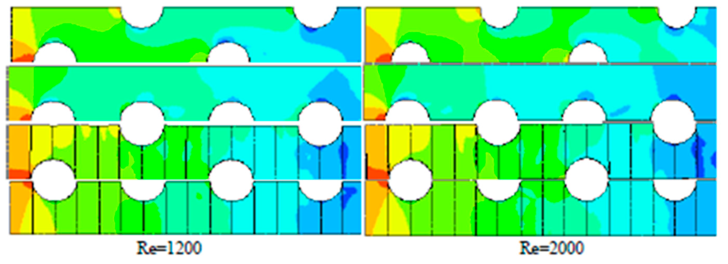
| Romero-Méndez et al. | - 1-row plate-finned tube HX - Different fin space | 3D simulation (260 ≤ Re ≤ 1640) | - | [77] |
| Tutar et al. | - 1-rowplate-fin HX - Different fin space | 3D simulation (1200 ≤ Re ≤ 2000) | - | [78] |
| Zhang and Zhang | - Evaporator | Transient simulation Moving boundary approach | - | [79] |
| Willatzen et al. Pettit et al. | - Evaporator/condenser | Transient simulation | - | [80,81] |
| Shao and Zhang | - Evaporator/condenser | Transient simulation Logic unconstrained multi-zone model | - | [82] |
| Illan-Gomez et al. | - Evaporator | Transient simulation segment-by-segment approach | ±10% for heat transfer rate ±10% for refrigerant inlet pressure ±2 °C for refrigerant inlet temperature ±1 °C for refrigerant outlet temperature | [83] |
| Starace et al. Fiorentino et al. | - Evaporator/condenser/crossflow compact HX - Complex circuitry layout | Control volume approach Multi-scale model | ±3% for outlet temperature ±4% for outlet relative humidity | [84,86,87,88,89,90] |
Disclaimer/Publisher’s Note: The statements, opinions and data contained in all publications are solely those of the individual author(s) and contributor(s) and not of MDPI and/or the editor(s). MDPI and/or the editor(s) disclaim responsibility for any injury to people or property resulting from any ideas, methods, instructions or products referred to in the content. |
© 2023 by the authors. Licensee MDPI, Basel, Switzerland. This article is an open access article distributed under the terms and conditions of the Creative Commons Attribution (CC BY) license (https://creativecommons.org/licenses/by/4.0/).
Share and Cite
Macchitella, S.; Colangelo, G.; Starace, G. Performance Prediction of Plate-Finned Tube Heat Exchangers for Refrigeration: A Review on Modeling and Optimization Methods. Energies 2023, 16, 1948. https://doi.org/10.3390/en16041948
Macchitella S, Colangelo G, Starace G. Performance Prediction of Plate-Finned Tube Heat Exchangers for Refrigeration: A Review on Modeling and Optimization Methods. Energies. 2023; 16(4):1948. https://doi.org/10.3390/en16041948
Chicago/Turabian StyleMacchitella, Silvia, Gianpiero Colangelo, and Giuseppe Starace. 2023. "Performance Prediction of Plate-Finned Tube Heat Exchangers for Refrigeration: A Review on Modeling and Optimization Methods" Energies 16, no. 4: 1948. https://doi.org/10.3390/en16041948