Article

A Hierarchical Cooperative Frequency Regulation Control Strategy of Wind-Storage-Load in a Microgrid Based on Model Prediction

1
State Grid Hubei Electric Power Company Economic & Technology Research Institute, Wuhan 430077, China
2
State Grid Hubei Electric Power Research Institute, Wuhan 430077, China
3
State Key Laboratory of Advanced Electromagnetic Engineering and Technology, School of Electrical and Electronic Engineering, Huazhong University of Science and Technology, Wuhan 430074, China
*
Author to whom correspondence should be addressed.
Energies 2023, 16(4), 1886; https://doi.org/10.3390/en16041886
Submission received: 4 January 2023 / Revised: 1 February 2023 / Accepted: 6 February 2023 / Published: 14 February 2023
(This article belongs to the Special Issue Control of Renewable Power Generation and Microgrids)

Abstract

:
In order to give full play to the frequency regulation ability of multiple types of resources such as wind power, energy storage, and controllable load in a microgrid, this paper proposes a hierarchical cooperative frequency regulation control strategy of wind-storage-load in a microgrid based on model prediction. Firstly, according to the operation characteristics of each resource in the microgrid, a hierarchical cooperative frequency regulation architecture of wind-storage-load is constructed. On this basis, the frequency regulation control models of wind power, energy storage, and controllable load are established, respectively, and the calculation method of the characteristic index of the system frequency response is proposed. Then, taking the maximum frequency deviation as the stratification index, a hierarchical cooperative frequency regulation control strategy of wind-storage-load based on model prediction is proposed, and a power compensation strategy for connecting the wind turbine frequency support is proposed for the wind turbine speed recovery stage. Finally, a microgrid model including wind power, energy storage, and controllable load is built on Matlab/Simulink for simulation analysis. The simulation results show that the proposed control strategy can control wind power, energy storage, and controllable load to participate in frequency modulation in advance, and improve the frequency stability of the system.

1. Introduction

In recent years, microgrids, as a small power system integrating distributed renewable energy generation, have been rapidly developing [1]. The proportion of wind power and other renewable energy generation in the microgrid is increasing, making the microgrid more environmentally friendly. However, wind turbines are connected to the grid through power electronic equipment, and their rotor speed is decoupled from the grid frequency, so they cannot directly provide frequency support, which reduces the inertia of the microgrid and weakens its ability to withstand frequency fluctuations, bringing severe challenges to the frequency stability of the microgrid [2,3].
In order to improve the frequency stability of the microgrid, scholars have proposed applying additional frequency controls to the wind turbine, endowing it with frequency regulation capability. References [4,5,6] adopt virtual inertia control for a doubly-fed induction generator (DFIG), which can create large virtual inertia on the rotor side of the DFIG. It provides inertia support for the system by releasing the kinetic energy of the rotor, and has a fast response speed. However, excessive rotor speed descendance may cause a secondary drop in the system’s frequency. In order to improve the primary frequency regulation capability of the DFIG, virtual inertia control, overspeed load cutting control [7,8,9], and pitch angle control [10,11] are usually combined. The above control strategies make the DFIG deviate from the maximum power point and can use the rotor kinetic energy of DFIG to support the frequency of the grid. However, the above control strategies cannot maximize the use of wind energy.
The rapid development of energy storage technology has blazed a new path for the frequency regulation of the microgrid. Energy storage has the advantages of fast response and flexible adjustment, which can assist wind power to provide frequency support [12]. At the same time, certain loads featuring energy storage characteristics in the microgrid such as air conditioners, electric water heaters, and electric vehicles can provide power support for the microgrid through demand response [13]. In reference [14], diesel generators and battery energy storage systems are used to regulate the frequency of microgrids. The control scheme coordinates the diesel generators and battery energy storage systems by continuously adjusting the active power drop parameters and voltage set points to obtain the best frequency response. Reference [15] designs the hierarchical frequency control structure according to the different net load fluctuation ranges and control characteristics of the battery storage system and diesel generator. The battery storage system is used for primary frequency regulation and the diesel generator is used for secondary frequency regulation. In reference [16], energy storage is configured to assist DFIG to participate in primary frequency modulation, effectively improving the frequency stability of the system. Reference [17] proposed a coordinated control strategy of air-conditioning load for frequency regulation, aiming at the problems of short-term power fluctuation and system inertia reduction. Among them, frequency conversion air conditioning is used for primary frequency regulation, and fixed frequency air conditioning is used for secondary frequency regulation. The frequency stability of the system is improved with fewer communication demands. In reference [18], electric vehicles are used in the frequency modulation auxiliary service of a power system and a two-level hierarchical control mechanism is proposed to minimize grid-level frequency deviation and maximize the income of electric vehicles. Most of the above research focuses on the coordinated control of wind-storage systems or frequency regulation control of a controllable load, and few focus on how to coordinate wind power, energy storage and controllable load to participate in frequency regulation. At the same time, the above studies all adopt real-time control, which cannot precaution the severity of a system frequency drop. When the sudden change in load is large, the frequency regulation resources in the system may not be able to respond in time, which may cause a serious frequency drop.
Taking the deficiencies of the above research into account, this paper proposes a hierarchical cooperative frequency regulation control strategy of wind-storage-load in a microgrid based on model prediction.
The contributions of this paper are summarized as follows:
(1)
The hierarchical cooperative frequency regulation architecture of wind-storage-load is constructed based on the operation characteristics of resources in a microgrid.
(2)
The calculation method of the system frequency response characteristic index is proposed based on the frequency regulation control models of wind power, energy storage and controllable load.
(3)
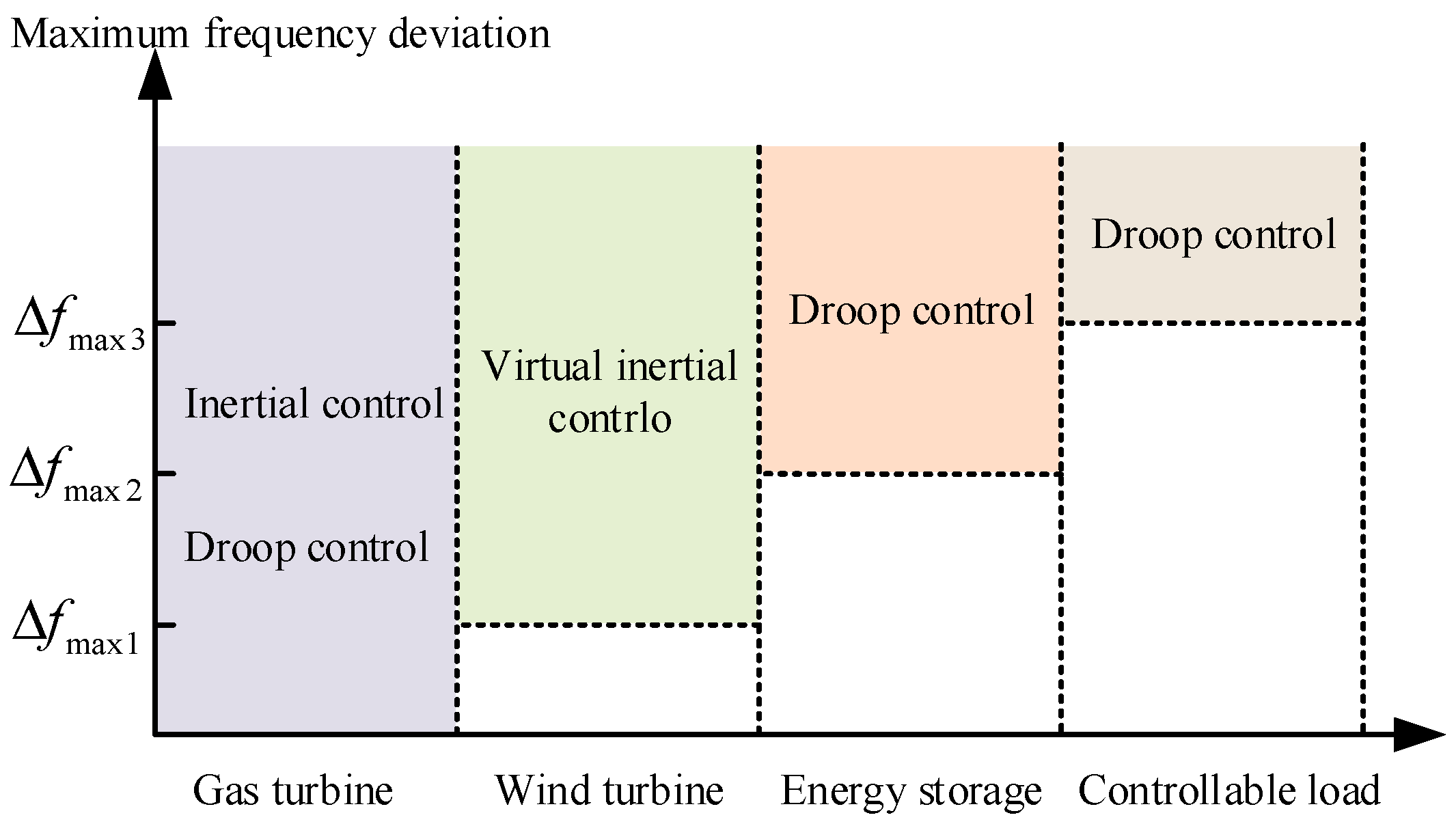
Taking the maximum frequency deviation as the stratification index, a hierarchical cooperative frequency regulation control strategy based on model prediction is proposed.
(4)
A power compensation strategy for connecting the wind turbine frequency support is proposed for the wind turbine speed recovery stage.
This paper is organized as follows. Section 2 describes the hierarchical cooperative frequency regulation structure of wind-storage-load. Then, the frequency regulation control models of gas turbine, DFIG, energy storage and controllable loads are built, respectively, in Section 3. Section 4 establishes the prediction model of the system frequency response characteristic index and proposes a hierarchical cooperative frequency regulation control strategy based on model prediction. Simulations are performed to verify the correctness and effectiveness of the strategy in Section 5. Finally, this study is concluded in Section 6.

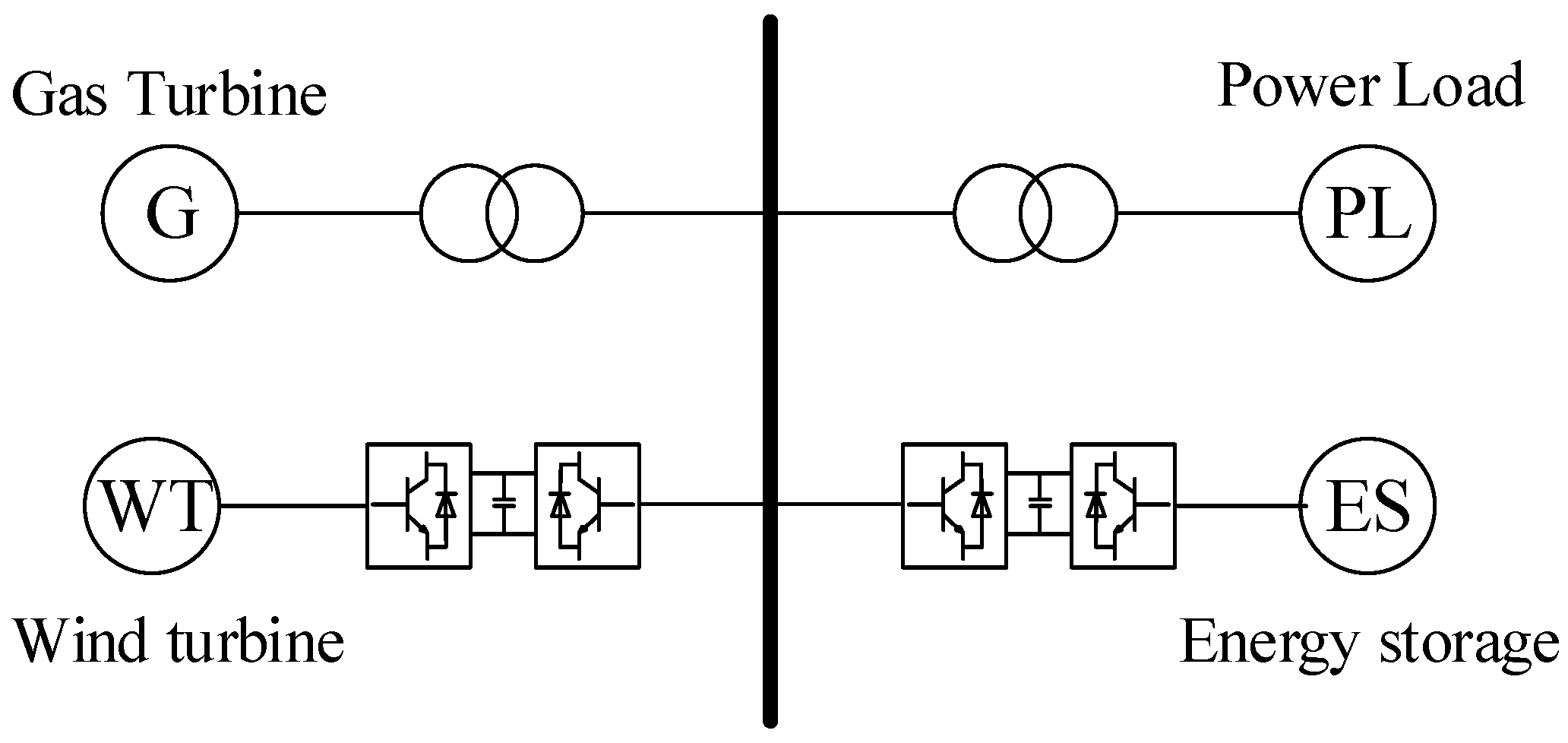
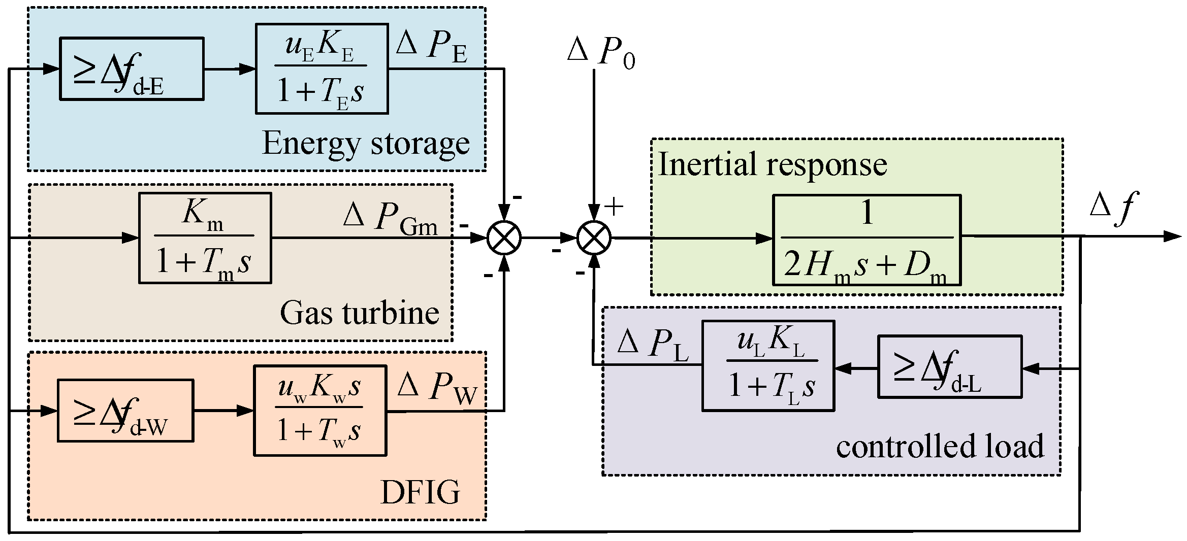
2. Hierarchical Cooperative Frequency Regulation Structure of Wind-Storage-Load

The microgrid refers to a small power generation and distribution system with a cluster of loads, distributed generation units, and energy storage systems operating in coordination to reliably supply electricity, which can be connected to the grid or in isolation [19]. The proposed approach is used with a microgrid when working in an isolated mode of operation. In order to verify the validity of the proposed approach, a typical microgrid based on gas turbine and DFIG is taken. The microgrid system structure including gas turbine, wind power, energy storage and controllable loads is shown in Figure 1. Among them, the gas turbine is directly connected to the microgrid. The wind turbine is represented by a doubly fed induction generator (DFIG), which are connected to the microgrid through voltage-type PWM converters. The energy storage, represented by electrochemical energy storage, is connected to the microgrid through DC/DC and DC/AC converters. The load is divided into controllable and uncontrollable ones, which are connected to the microgrid through the step-up transformer.
When the microgrid works in an isolated mode of operation, its frequency stability is poor due to the lack of support from the grid, and the gas turbines usually carry the responsibility of frequency regulation [19]. Thus, it is assumed that the gas turbine always has to be used in frequency regulation. At the same time, the installed capacity of the wind turbine is large and the wind power permeability is high. According to the Technical Regulations on the Access of Wind Farm to the Power System, the wind turbine connected to grid needs to have inertia support and primary frequency regulation capability, so the wind turbine is preferentially participated in frequency regulation. For energy storage, it is expensive to build and maintain, so its capacity takes up a relatively small proportion in the microgrid, which is usually used to provide frequency support [16]. Therefore, energy storage is set to participate in frequency regulation when the frequency regulation capacity of the gas turbine and DFIG is insufficient. For controllable load, the regulation of it will affect the power demand of users. To ensure the reliability of power consumption, controllable loads will participate in frequency regulation only when the frequency regulation capacity of all these resources is difficult to ensure the safety requirements. Therefore, in order to make full use of the frequency regulation capability of wind power, energy storage, and controllable load, and at the same time consider the economy of each resource regulation, this paper adopts a hierarchical collaborative control architecture, setting different frequency limits for each frequency regulation resource, and cooperatively controlling the working state of each resource by detecting or predicting the maximum deviation of the system frequency, as shown in Figure 2.
The architecture is divided into four layers: the first layer is gas turbine frequency regulation. When the system frequency changes, the gas turbine responds at any time. The second layer is wind turbine frequency regulation. When the maximum frequency deviation of the system is predicted to exceed Δ f d-W , which is the action threshold of the wind turbine participating in primary frequency regulation, the wind turbine adopts virtual inertia control to reduce frequency change. The third layer is the frequency regulation of the energy storage system. When the maximum frequency deviation is predicted to exceed Δ f d-E , which is the action threshold of energy storage participating in primary frequency regulation, the energy storage adopts droop control. The fourth is controlled load frequency regulation. When the maximum frequency deviation of the system is predicted to exceed Δ f d-L , which is the action threshold of controlled load participating in primary frequency regulation, the controlled load adopts droop control by increasing or decreasing the load power to reduce the frequency deviation.

3. Frequency Regulation Control Model of Wind-Storage-Load

When a fault or load disturbance occurs in the microgrid, the original power balance of the system is broken, and the frequency starts to change. Under the effect of various frequency regulation resources, the system power reaches a new balance, and the frequency reaches a new stable value. Additionally, each resource realizes frequency regulation mainly through inertia control and droop control. Inertia control is related to the system frequency change rate, which can hinder the system frequency change and restrain the frequency fluctuation. The droop control is related to the system frequency deviation, which can reduce the deviation and promote the recovery of the system frequency. The coordination of inertia control and droop control can effectively improve the frequency stability of the microgrid.

3.1. Gas Turbine Frequency Regulation Control Model

3.1.1. Inertial Response Model

The inertia of the microgrid reflects the frequency stability, which is usually supported by the gas turbine. During normal operation, the mechanical torque of the gas turbine is balanced with electromagnetic torque and friction damping. When faults or disturbances occur, the electromagnetic torque of the gas turbine suddenly changes, and its rotor kinetic energy is used to balance the load change. The rotor motion state meets the rotor motion equation:
Δ P Gm Δ P Ge = 2 H m d Δ f d t + D m Δ f
where, Δ P Gm is the variation in the mechanical torque of the gas turbine; Δ P Ge is the variation in electromagnetic torque; H m is the inertia time constant of the gas turbine; D m is the damping coefficient of the gas turbine; Δ f is the change in system frequency.

3.1.2. Primary Frequency Regulation Model

The gas turbine has the ability of primary frequency regulation, which is realized through its speed regulation system. It detects the difference between the rotor speed and the rated speed in real time and drives the turbine valve to act through the integrated amplifier and PID control link, thus realizing the control of the input mechanical power.
The complex frequency domain expression of gas turbine primary frequency regulation is [8]:
Δ P Gm = K m 1 + T m s Δ f ( s )
where, K m is the power frequency characteristic coefficient of the gas turbine; T m is the response time constant of the gas turbine.

3.2. DFIG Frequency Regulation Control Model

3.2.1. Virtual Inertial Control

The rotor of DFIG contains a large amount of rotational kinetic energy, which has the ability to provide inertia for the grid. However, DFIG is connected to the grid through an electronic converter, and its rotor is decoupled from the grid, so it cannot respond to the change in system frequency. Therefore, it is necessary to release the kinetic energy of the rotor through the corresponding auxiliary control to provide inertia support.
Referring to the inertia control principle of traditional thermal power units, the virtual inertia control is adopted; that is, within the rotor speed safety range (0.67–1.33 p.u.), the output of DFIG is controlled in direct proportion to the frequency change rate to slow down the frequency change. The control equation is [8]:
Δ P W ( s ) = K w s 1 + T w s Δ f ( s )
where, Δ P W is the power regulation volume of DFIG; K w is the virtual inertial coefficient; T w is the response time constant of the control system.
Meanwhile, DFIG should meet the following constraints:
Rotor speed constraint:
ω min ω ω max
where, ω is the rotor speed of DFIG; ω min and ω max are, respectively, the minimum and maximum rotor speed.
Rotor current constraint:
I wr min I wr I wr max
where, I wr is the rotor current of DFIG; I wr min and I wr max are, respectively, the minimum and maximum rotor speed.

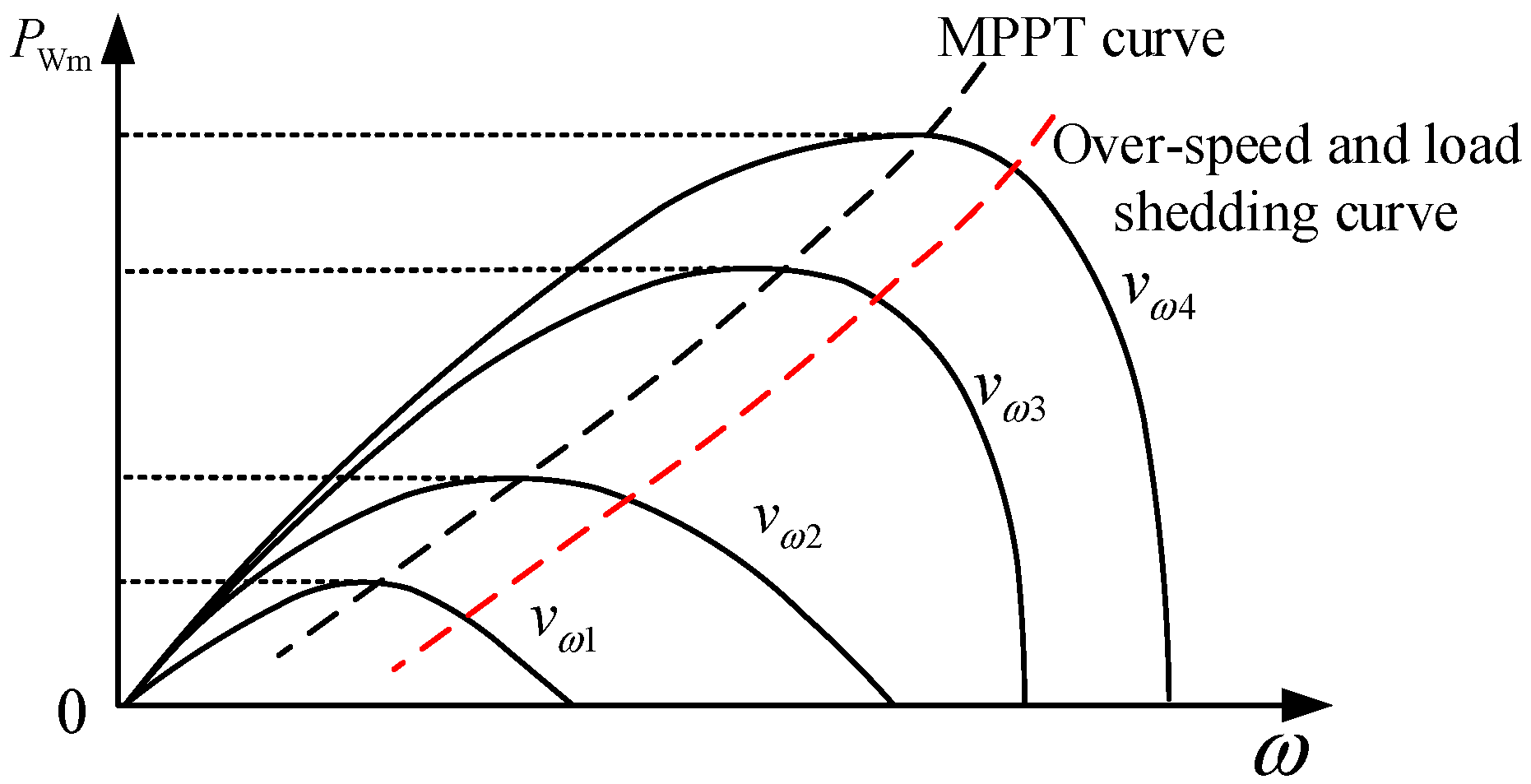
3.2.2. Over-Speed and Load Shedding Control

According to aerodynamic theory, the DFIG mechanical kinetic energy output is:
P Wm = 1 2 C p ρ a S w V ω 3
where, P Wm is the DFIG mechanical power output; C p is the wind energy conversion coefficient, which is related to the pitch angle, wind speed and fan speed; ρ a is the air density; S w is the fan blade area of the wind turbine; V ω is the wind speed.
In order to make full use of wind power, DFIG usually adopts maximum power point tracking (MPPT) control; that is, under a certain wind speed and a fixed pitch angle, the output of DFIG is maximized by regulating the rotor speed. Meanwhile, DFIG is in hyper-synchronous mode, and its stator and rotor both provide power to the microgrid. Additionally, PQ control is adopted to control the total output power of the stator and rotor. However, when participating in frequency regulation, DFIG needs to consume its rotor kinetic energy to provide power support for the grid. If DFIG is still operating at the maximum power point, it will consume a lot of rotor kinetic energy. Due to the limitation of the rotor safety speed, the frequency regulation capacity provided by DFIG is small. At the same time, it will absorb more energy from the grid during the rotor speed recovery process, causing serious secondary frequency drop. Therefore, DFIG needs to reserve a certain frequency regulation standby power, which can usually be operated on both sides of the maximum power point, namely overspeed control or deceleration control. However, it is found that the deceleration control will engender static instability [20], hence overspeed control is adopted, and the power-speed curve under different wind speeds is shown in Figure 3. Defining the load cutting power ratio as the ratio of the output power when the DFIG operates in load cutting mode to the maximum output power of DFIG, namely:
η = P opt P max
where, η is the load cutting power ratio; P max is the maximum of output power; P opt is the actual output power.
In overspeed and load shedding mode, the extra power of DFIG will participate in frequency regulation, improving its frequency regulation capability, as shown in Formula (8).
Δ P opt = P max ( 1 η )
At this stage, the change curve of electromagnetic power and mechanical power during frequency regulation of DFIG is shown in Figure 4. During the normal operation, DFIG stably operates at point a. When the load suddenly increases due to grid fault, the system frequency decreases. Under the virtual inertia control of Equation (3), the DFIG electromagnetic power output will increase to point b. At this time, the mechanical power is still at point a, less than the electromagnetic power. The DFIG starts to release the rotor kinetic energy, and the speed gradually decreases. In the process of frequency regulation, the frequency change rate will gradually decrease due to the regulation of frequency regulation resources. The electromagnetic power of DFIG will gradually decrease along the curve bc, the rotor speed will also decrease from ω 2 to ω 3 , and the mechanical power will first rise and then decline along the curve ac. The system frequency will reach the lowest point at c. Then, the frequency starts to rise. Under the control of Formula (3), the DFIG electromagnetic power will be reduced to point d, less than the mechanical power, and the rotor speed starts to recover. In this process, the DFIG electromagnetic power will gradually rise along the curve da, and the mechanical power will return along the curve ca, finally stabilizing at the initial operating point a.
To sum up, the overspeed control uses the mechanical power reserved by DFIG in frequency regulation process. Under the same frequency regulation capacity, compared with MPPT control, the rotor speed conversion range of DFIG with overspeed control is smaller. Meanwhile the remaining mechanical power also speeds up the speed recovery of the DFIG.

3.3. Energy Storage Frequency Regulation Control Model

Electrochemical energy storage has the advantages of fast response, high energy density, flexible power regulation, etc. It can quickly charge and discharge to provide effective frequency support for the system in case of grid failure. At present, the research on electrochemical energy storage has been relatively mature and widely applied.
The energy storage system is connected to the grid through a bidirectional converter, and the power is decoupled from the grid. When it participates in frequency regulation, its charging and discharging power can be controlled by the converter to meet the frequency regulation requirements. The state of charge λ soc is usually used to represent the energy stored in the system; its operating characteristics are:
λ soc = λ soc 0 η E P E d t E N
η E = η c P E 0 1 η d P E > 0
where, λ soc 0 is the initial state of charge of the energy storage; P E is the output of the energy storage; E N is the capacity of the energy storage; η c is the charge efficiency of the energy storage; η d is the discharge efficiency of the energy storage.
Meanwhile, the energy storage should meet the following constraints:
Output power constraint:
P E min P E P E max
where, P E min and P E max are, respectively, the minimum and maximum output power.
The state of charge constraint:
λ soc min λ soc λ soc max
where, λ soc min and λ soc max are, respectively, the minimum and maximum state of charge.
Current surge constraint:
I E min I E I E max
where, I E is the current of the energy storage; I E min and I E max are, respectively, the minimum and maximum current.
In order to give play to the frequency regulation capability of the energy storage, droop control is usually used to provide power support for the grid, which is [15]:
Δ P E ( s ) = K E 1 + T E s Δ f ( s )
where, Δ P E is the power regulation value of the energy storage; K E is the droop coefficient; T E is the response time constant of the energy storage.

3.4. Controllable Load Frequency Regulation Model

The volume of user-side load is huge, which can be divided into important load, transferable load and interruptible load according to their importance. Among them, important load has high requirements for power reliability, and power failure is not allowed within a specific time. Transferable load and interruptible load can participate in the grid regulation within a certain range. Typical load includes air conditioners, electric water heaters, electric vehicles, etc. Under the support of demand response, it can provide power support after failure and promote the recovery of the system frequency by regulating its own power through direct load control.
The number of controllable loads in the microgrid is large and decentralized. If decentralized control is adopted, the cost will be greatly increased. Therefore, the controllable load can be aggregated into a whole to participate in the grid frequency regulation in a unified way, while giving users compensation. Droop control is usually used to provide power support for the grid, which is:
Δ P L ( s ) = K L 1 + T L s Δ f ( s )
where, Δ P L is the power regulation volume of controllable load; K L is the droop coefficient; T L is the response time constant of controllable load.
To sum up, the overall frequency response model of the system including wind power, energy storage and controllable load is shown in Figure 5. The mathematical expression of the model is:
Δ f Δ P 0 = H s 1 + H s ( G T + u w G w + u E G E + u L G L ) H s = 1 2 H m s + D m G T = K m 1 + T m s G w = K w s 1 + T w s G E = K E 1 + T E s G L = K L 1 + T L s
where, Δ P 0 is the system load disturbance; H s is the transfer function of system inertial response; G T , G w , G E , G L are, respectively, the frequency response transfer functions of the gas turbine, DFIG, energy storage system and controllable load; u w , u E , u L are, respectively, binary variables of DFIG, energy storage system and controlled load, which are 1 when participating and 0 when not participating in frequency regulation.
Through the coordinated frequency regulation of DFIG, energy storage and controllable load, the transient frequency stability of the microgrid can be effectively improved and the frequency deviation of the system can be reduced. However, in the long-run, the power balance of the system still needs to be maintained by the gas turbine.

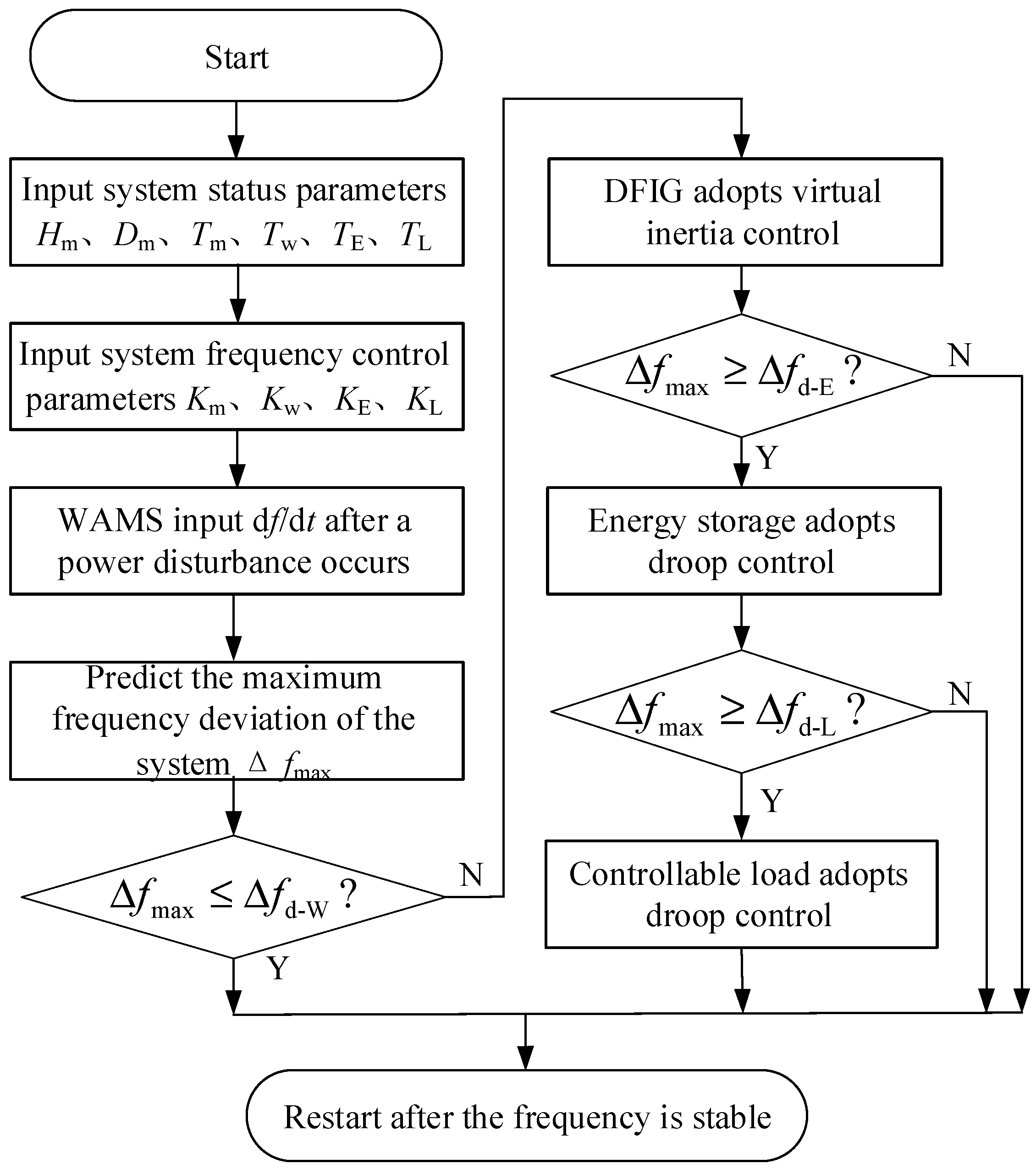
4. Hierarchical Cooperative Control Strategy Based on Model Prediction

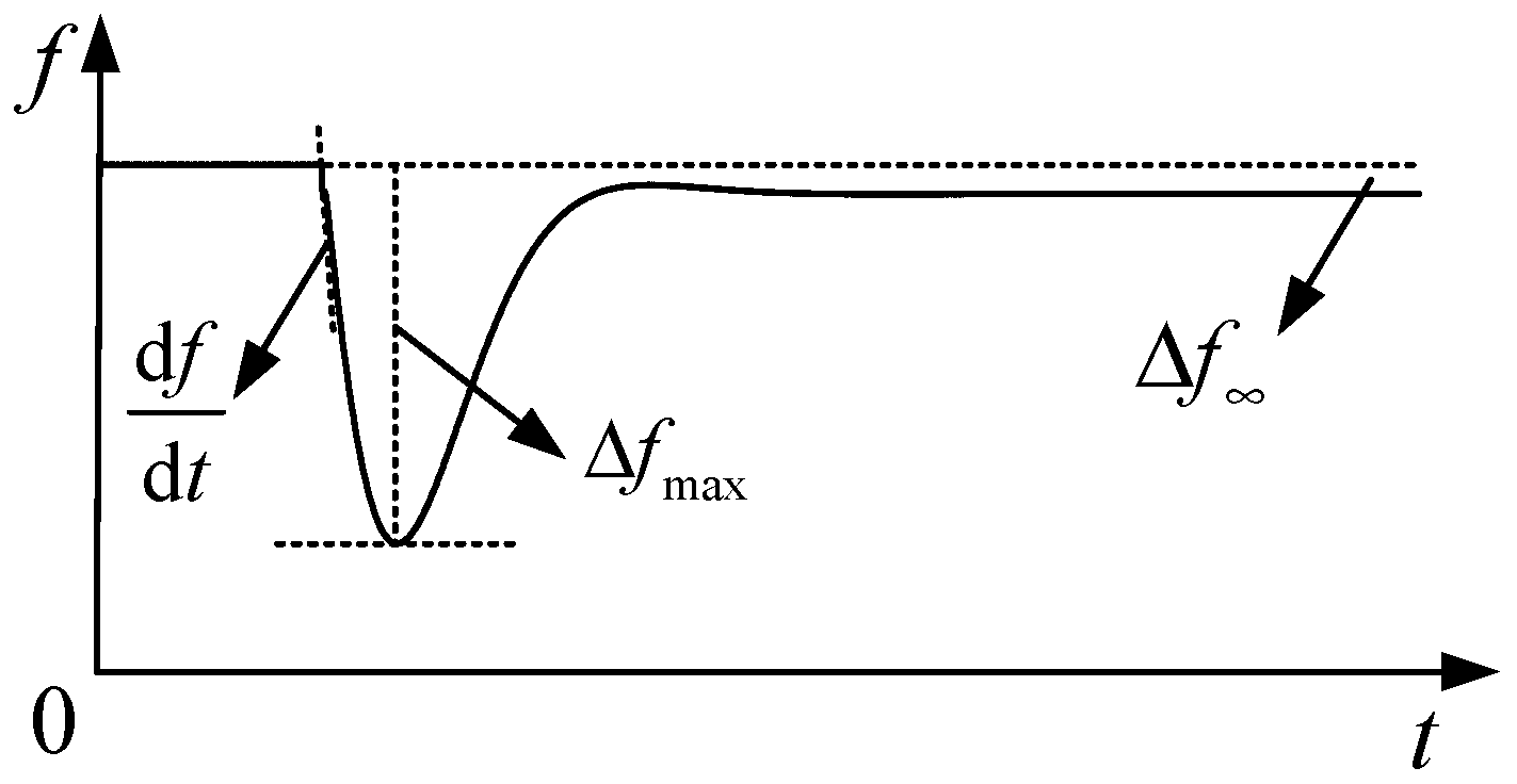
4.1. Target of System Frequency Regulation

When the load suddenly increases due to grid failure, the change in system frequency under the action of various frequency regulation resources is shown in Figure 6.
According to Figure 6, the characteristic indices of the system frequency response mainly include the maximum frequency change rate, the maximum frequency deviation and the steady-state frequency deviation. Among them, the steady-state frequency deviation reflects the stability of the system in the long term under primary frequency regulation, while the maximum frequency change rate and the maximum frequency deviation reflect the short-term stability of the system.
According to the system frequency response model in Equation (16), when the disturbed load is Δ P 0 ( s ) = Δ P 0 / s , the initial frequency change rate (maximum frequency change rate) of the system can be obtained from the initial value theorem as follows:
( d f d t ) max = lim s s ( s Δ f ( s ) ) = Δ P 0 2 H m
According to the terminal value theorem, the steady-state frequency deviation of the system is:
Δ f = lim s 0 s Δ f ( s ) = Δ P 0 D m + K m + u E K E + u L K L
In order to solve the analytical expression of the maximum frequency deviation, the time domain expression of Δ f needs to be solved, and the time domain expression is derived from time, so as to find the maximum frequency deviation and its time. However, it can be seen from Equation (16) that the system is a high-order system, making it difficult to analytically calculate the maximum frequency deviation time after it is converted into a time-domain expression, so it is necessary to reduce the order of the system. With observation Formula (16), the transfer functions of the gas turbine, DFIG, energy storage system and controlled load primary frequency regulation share the same form, which can be expressed as:
G = A s + B 1 + C s
where, A, B and C are characteristic parameters.
Therefore, the frequency regulation model of each resource in the system can be equivalent to a frequency regulation model with the same characteristics. Reference [20] shows that the transfer function expression of the equivalent frequency regulation model is:
G eq = A eq s + B eq 1 + C eq s B eq = K m + u E K E + u L K L A eq C eq = u w K w 1 + T w s B eq ( B eq A eq C eq ) e t mid C eq = K m ( 1 e t mid T m ) + u w K w T w e t mid T w + u E K E ( 1 e t mid T E ) + u L K L ( 1 e t mid T L ) t mid = K m t m s + u w K w t w s + u E K E t E s + u L K L t L s 2 ( K m + u w K w + u E K E + u L K L )
where, A eq , B eq , C eq are characteristic parameters of the equivalent model; t mid is half of the weighted average value of the steady-state time of each resource; t m s , t w s , t E s , t L s are, respectively, gas turbine, DFIG, energy storage system, and controlled load frequency regulation steady-state time. See reference [21] for the detailed derivation process.
The time series expression of the frequency deviation equivalent frequency response model can be obtained as follows:
Δ f ( t ) = M + N e a t cos ( b t arctan h g )
where, M = Δ P 0 B eq + D eq ; N = 2 Δ P 0 g 2 + h 2 c 2 + d 2 ; a = 2 H s + A eq + C eq D eq 4 H s C eq ; b = B eq + D eq 2 H s C eq a 2 ; c = 6 H s C eq a 2 b 2 + 2 a 2 H s + A eq + C eq D eq + B eq + D eq ; d = 12 a b H s C eq + 2 b 2 H s + A eq + C eq D eq ; g = a C eq + 1 c + b d C eq ; h = b c C eq a C eq + 1 d .
After derivation of Equation (21) with respect to time, the system maximum frequency deviation and its time can be obtained as follows:
t tir = arctan ( a / b ) arctan ( h / g ) b
Δ f max = M + N e a t tir cos ( b t tir arctan h g )
It can be seen from Equations (17), (18) and (23) that under certain load disturbance, the maximum frequency change rate of the system is only related to the inertia of the gas turbine. Hence, as many gas turbines as possible should be connected to the power grid to increase the system inertia. The steady-state frequency deviation of the system is related to the damping coefficient of the gas turbine and the droop coefficient of its governor, the energy storage system, and the controllable load. Therefore, putting the energy storage system and the controllable load into frequency regulation and increasing the droop coefficient can effectively reduce the steady-state frequency deviation. The maximum frequency deviation is related to the operation and control parameters of each frequency regulation resource. Increasing the inertia of the gas turbine, putting each resource into frequency regulation and increasing the coefficient of each resource can reduce the maximum frequency deviation of the system.
In conclusion, the maximum frequency change rate, maximum frequency deviation and steady-state frequency deviation are the system frequency safety and stability indicators. When fault occurs, the maximum frequency change rate, maximum frequency deviation and steady-state frequency deviation can be limited to a safe range through the frequency regulation of various resources, so as to meet the frequency security and stability requirements.

4.2. Hierarchical Cooperative Control Strategy Based on Model Prediction

In case of grid failure or load changing, if DFIG, energy storage, and controllable load all participate in frequency regulation, it will be unconducive to the system economy; If the system frequency regulation capacity is insufficient, it will be difficult to meet the requirements of frequency stability. Therefore, based on the frequency safety and stability index, the hierarchical cooperative frequency regulation control strategy is set in this paper.
It can be seen from the analysis in Section 4.1 that the maximum frequency change rate only relates to the inertia of the gas turbine, which is generally fixed to meet the requirements for frequency stability. At the same time, the steady-state frequency deviation reflects the frequency stability in the long run. However, this paper mainly focuses on the frequency stability under transient conditions. Hence, only the maximum frequency deviation of the system is considered as the wind-storage-load layered index of frequency regulation.
In the process of frequency regulation, if the system frequency deviation exceeds the layered index before the corresponding resources participating in frequency regulation, the frequency regulation capability of each resource will not be fully utilized, which may lead to the dynamic frequency out of limit. Therefore, it is necessary to predict the maximum frequency deviation, so as to control all resources to participate in frequency regulation in advance.
In the actual operation process of the microgrid, the power shortage is difficult to calculate in time after grid fault, and the initial frequency change rate can be measured in real time by a wide area measurement system (WAMS). When power disturbance occurs in the microgrid, the frequency begins to fluctuate. The initial frequency change rate is measured by the WAMS in time. Then, the unbalanced power can be calculated based on Equation (17). Additionally, the maximum frequency deviation can be predicted based on Equation (23) and then compared with the frequency regulation action threshold of each resource to determine whether the resource participates in frequency regulation. Thus, the predictive control of the wind-storage-load model is realized. The cooperative control flow chart is shown in Figure 7.

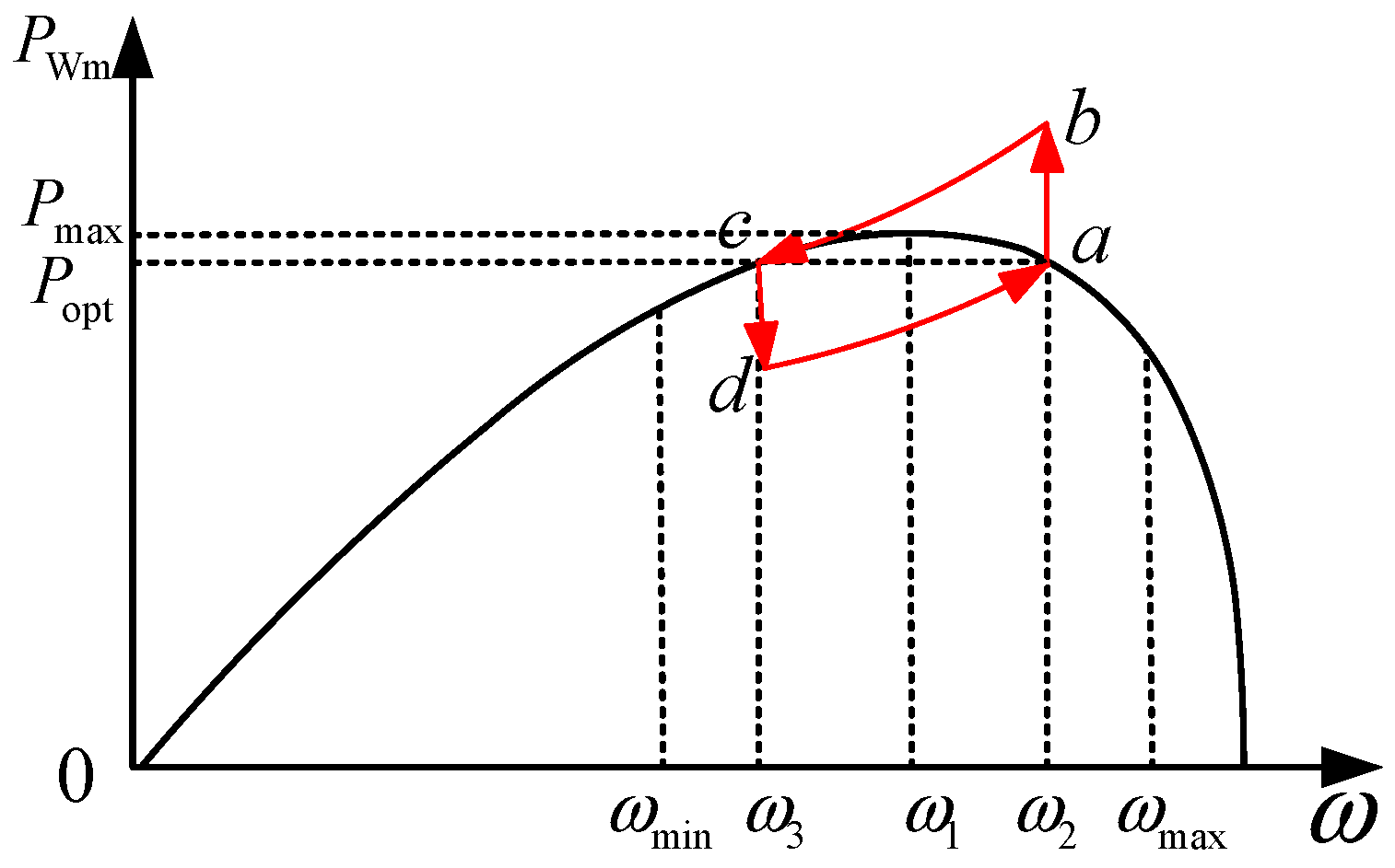
4.3. Power Compensation Strategy during Rotor Speed Recovery of DFIG

It can be seen from Figure 4 that when the DFIG is in the process of frequency recovery, the rotor speed increases from d to a gradually. During this process, the frequency change rate of the system changes from negative to positive. According to the virtual inertia control model of the DFIG, the output power of the DFIG will be less than the output power when the DFIG operates normally, resulting in a power shortage in the microgrid, which may cause a secondary frequency drop. Therefore, the system needs to provide additional power support during the rotor speed recovery process. In the proposed model, the energy storage can provide a large amount of power support in a short time due to its fast response speed, so the energy absorbed by the DFIG can be compensated until it returns to the initial operation state. Then, the energy storage starts to exit from frequency regulation smoothly, and the final frequency regulation power will be provided by all gas turbines.
After detecting that the system frequency change rate is 0, the frequency regulation control equation of the energy storage can be modified as follows:
Δ P E ( s ) = K E 1 + T E s Δ f ( s ) + K w s 1 + T w s Δ f ( s )

5. Example Test

5.1. Parameters Setting

In order to verify the effectiveness of the proposed model, this section builds a microgrid simulation model on Matlab/Simulink, as shown in Figure 1. The gas turbine capacity is 9 MW. As for the DFIG, it has a capacity of 6 MW and operates as shown in Figure 4 before the load step. The load cutting power ratio is 0.9. Meanwhile, DFIG is in hyper-synchronous mode and the slip rate is −0.2. The minimum and maximum rotor speed are, respectively, 0.67 and 1.33 p.u. The minimum and maximum rotor speed are, respectively, 0.6 and 1.5 p.u. As for the energy storage, the capacity is set as 20% of the wind capacity, 1.2 MW·h, and λ soc 0 = 0.5 . The minimum and maximum of state of charge are, respectively, 0.1 and 0.9. The minimum and maximum output power are, respectively, 0.2 and 1.2 p.u. The minimum and maximum current are, respectively, 0.2 and 1.2 p.u. The load size is 10 MW, and the proportion of controllable load is 20%. The frequency regulation model parameters of each resource are shown in Table 1. The primary frequency modulation action thresholds of wind turbine, energy storage and controllable load is set to 0.25 Hz, 0.5 Hz, and 0.75 Hz, respectively.

5.2. Results Analysis

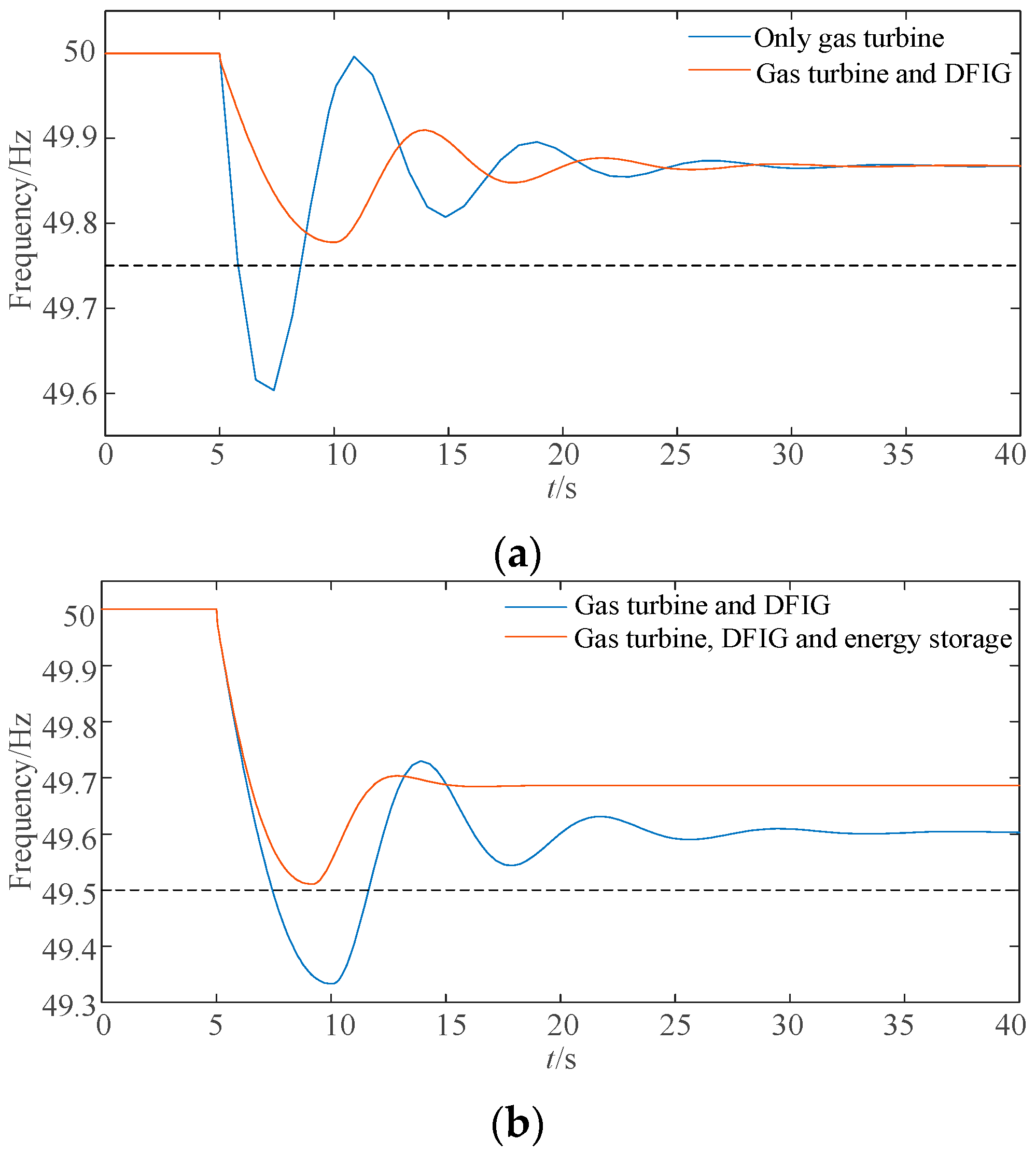
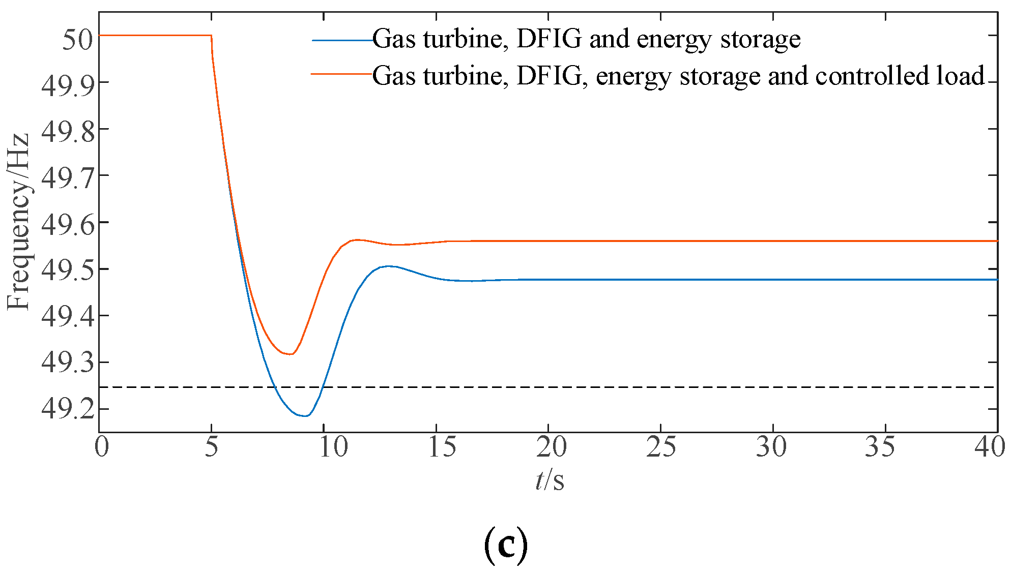
5.2.1. System Frequency Response Results under Different Load Disturbances

It can be seen from Section 4.2 that for different maximum frequency drop values, the frequency regulation resources participated are also different. In order to analyze the frequency regulation effect of each resource, this section sets three scenarios, namely, 0.5 MW, 1.5 MW, and 2.5 MW sudden load increase in 5 s. The maximum frequency deviation of the system is predicted based on the measured initial frequency change rate. The prediction results are shown in Table 2. In the three scenarios, the frequency response curve of the system is shown in Figure 8.
It can be seen from Table 2 that when the load suddenly increases by 0.5 MW, if only the gas turbine participates in frequency regulation, the maximum frequency deviation is predicted to be 0.394 Hz, greater than the layered index. Therefore, DFIG is required to participate. It can be seen from Figure 8a that the system frequency drops significantly before DFIG participates, with the maximum deviation reaching 0.395 Hz, which is basically consistent with the predicted one. After DFIG participates, under the control of virtual inertia, the maximum frequency deviation is reduced to 0.221 Hz, and the frequency drop speed slows down, which improves the frequency stability of the system. When the load suddenly increases by 1.5 MW, if only the gas turbine and DFIG participate, the maximum predicted frequency deviation is 0.666 Hz, and energy storage is required to participate. It can be seen from Figure 8b that after the energy storage participates, the maximum frequency deviation decreases to 0.485 Hz, and the steady-state frequency deviation minimizes, and the frequency stabilization time decreases to 20 s. When the load suddenly increases by 2.5 MW, if the gas turbine, DFIG and energy storage participate, the maximum predicted frequency deviation is 0.814 Hz, and the controllable load is required to participate. It can be seen from Figure 8c that after the controllable load participates, the maximum frequency deviation funnels to 0.682 Hz, and the steady-state frequency deviation also decreases.
To sum up, the proposed model in this paper has high accuracy and can predict the maximum frequency deviation of the system, so as to control the corresponding resources in frequency regulation in advance, reduce the frequency drop and improve the system frequency stability.

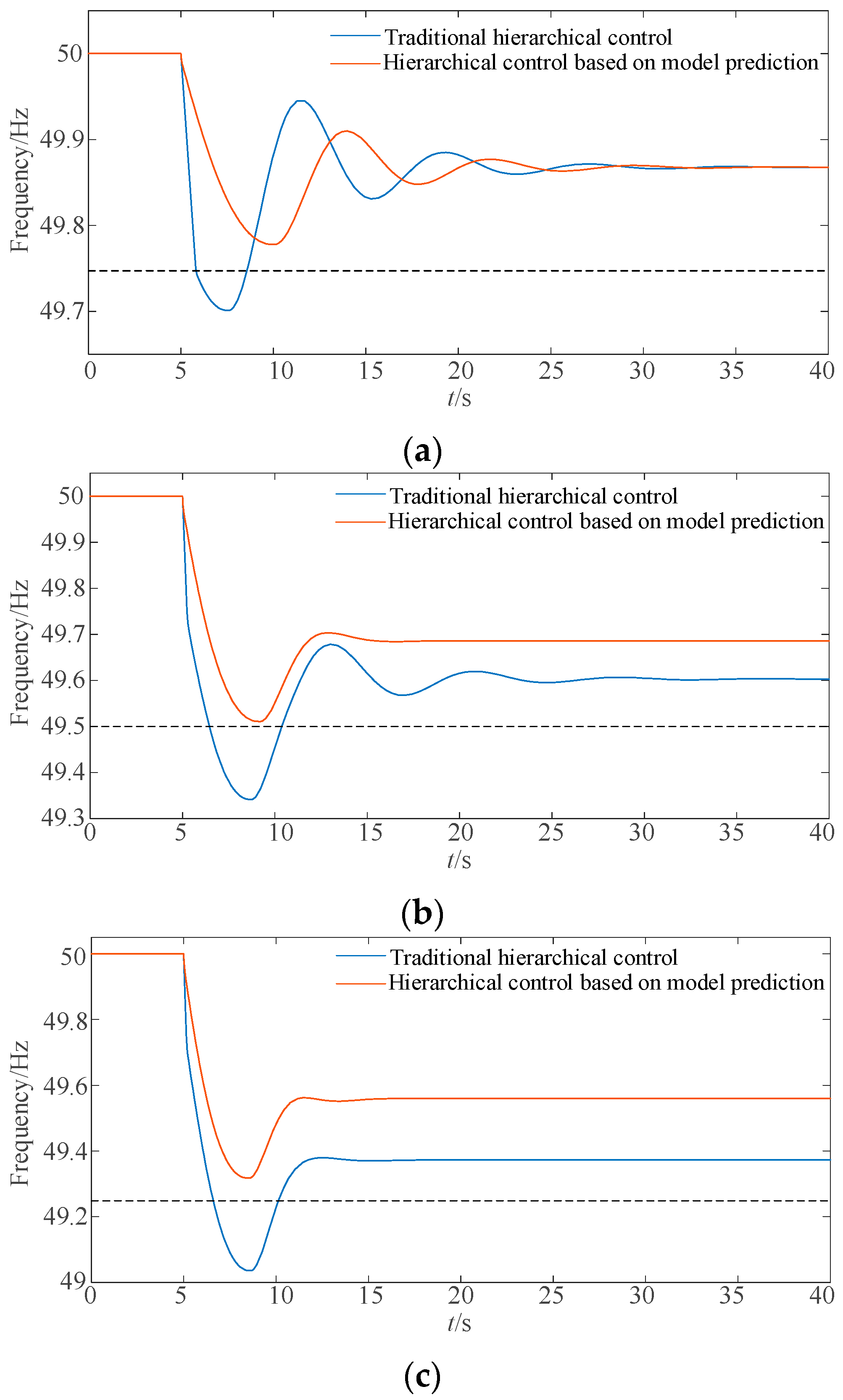
5.2.2. Comparison with Traditional Hierarchical Control Strategy

To further verify the effectiveness of the proposed model, this section compares the traditional hierarchical control strategy in the references [15,20], and the simulation results are shown in Figure 9. Among them, the traditional strategy is that each resource in the system automatically participates in frequency regulation when it detects that the frequency deviation exceeds the threshold in real time. The threshold in the comparison simulation is the same as that in the prediction model.
It can be seen from Figure 9 that under the proposed hierarchical control strategy based on model prediction, the system frequency deviation is significantly reduced compared with the traditional one, the frequency change rate is slowed down, and the stability time is also advanced. Taking the sudden load increase of 0.5 MW as an example, under a traditional hierarchical control strategy, DFIG will participate in frequency regulation only after the frequency deviation is detected to exceed 0.25 Hz. In comparison, the proposed strategy in this paper can control the DFIG to participate in frequency regulation in advance, reducing the deviation.
Therefore, by the traditional hierarchical control strategy, the resources will start to participate in frequency regulation only when the frequency reaches the threshold. However, by the proposed approach, the resources will start to participate in frequency regulation in advance, which can avoid excessive frequency drop of the system, and improve the system frequency stability.

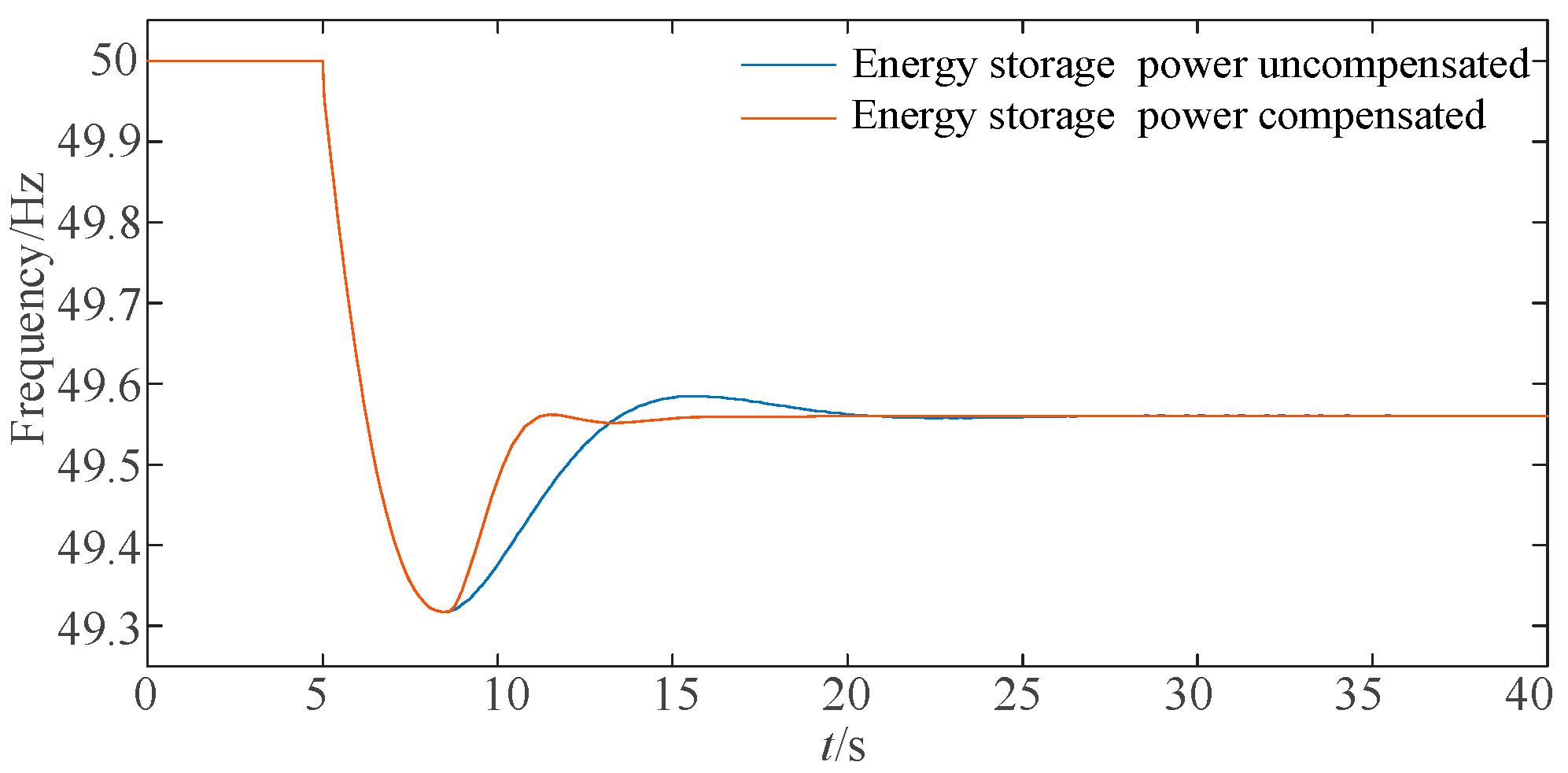
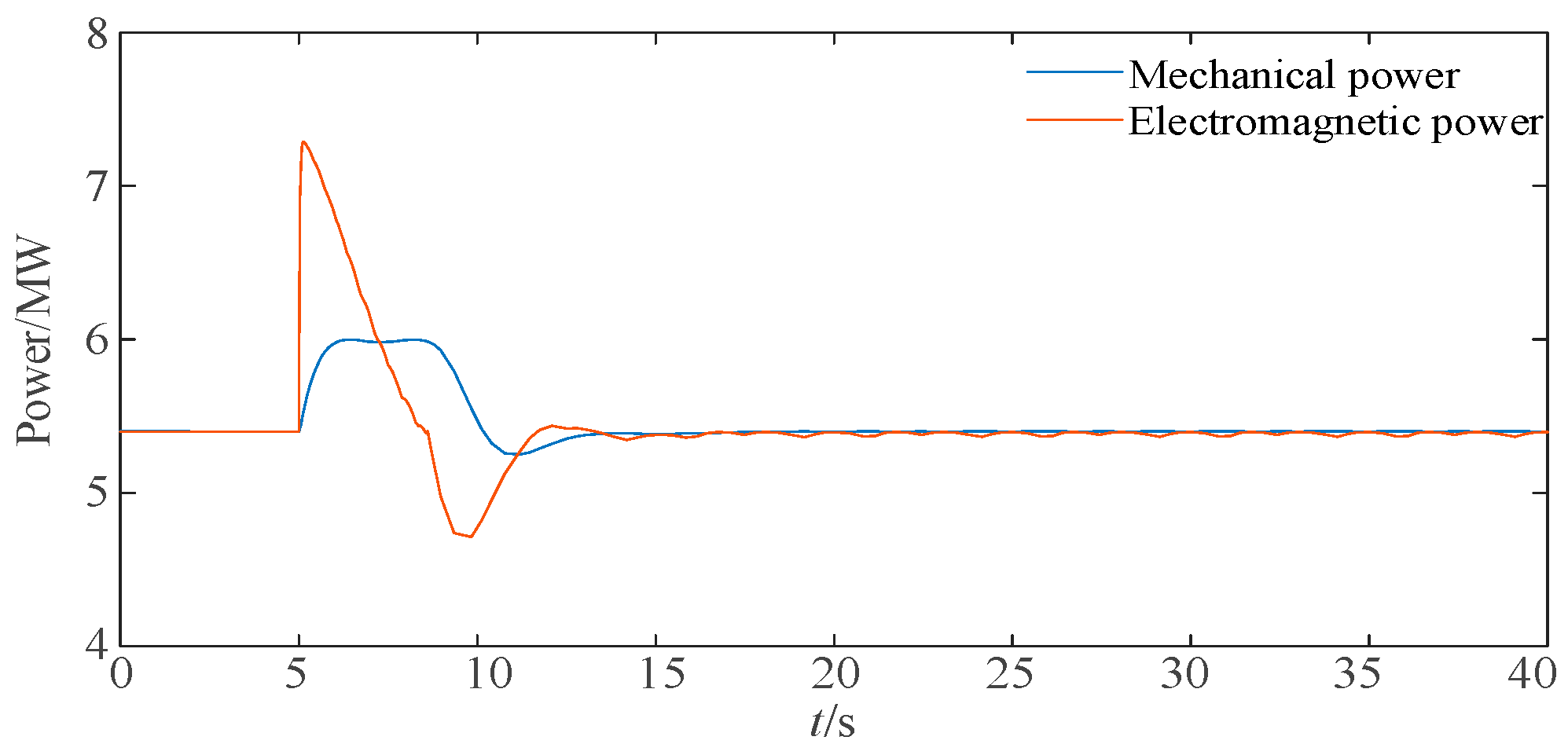
5.2.3. Validation of Fan Speed Recovery Control Strategy

To verify the effect of energy storage power compensation on the rotor speed of the DFIG recovery phase, this section compares the frequency response results of the system before and after energy storage compensation when the load suddenly increases by 2.5 MW, as shown in Figure 10. Figure 11, Figure 12 and Figure 13 show the power change in fan and energy storage and the speed change in the fan after energy storage compensation.
It can be seen from Figure 10, Figure 11 and Figure 12 that the system frequency will enter the recovery phase after reaching the lowest point, and the DFIG will absorb energy from the system, which is not conducive to frequency recovery. The system frequency will be stable at 20 s. When the power is compensated by energy storage, the frequency stability time of the system is advanced to 15 s, the frequency fluctuation is reduced, and the recovery speed is improved.
It can be seen from Figure 11 and Figure 13 that when the DFIG is running in the overspeed mode, the speed of DFIG decreases and the mechanical power increases, which prevents the rotor speed from dropping sharply. At the same time, in the process of speed recovery, higher mechanical power also increases the acceleration torque of the rotor, provides energy for the speed recovery, and reduces the energy absorbed from the system.

6. Conclusions

In order to give full play to the frequency regulation potential of DFIG, energy storage, and controllable load in the microgrid, and improve the frequency stability of the system, this paper proposes a hierarchical cooperative frequency regulation control strategy of wind-storage-load in a microgrid based on model prediction. Through theoretical and simulation analyses, the conclusions are as follows:
  • The proposed strategy fully considers the frequency regulation capability of various resources in the microgrid, and improves the frequency stability of the system through the coordinated frequency regulation control of the gas turbine, DFIG, energy storage, and controllable load.
  • The proposed strategy can predict the maximum frequency deviation of the system, control the corresponding resources to participate in frequency regulation in advance, which effectively reduces the system frequency deviation, and shortens the system stability arrival time.
  • In the process of rotor speed recovery of DFIG, the power absorbed by DFIG is compensated by energy storage, which can reduce the system frequency fluctuation, speed up the frequency recovery, and avoid the secondary frequency drop.
In the manuscript, there is no application of power system stabilizers (PSS). A frequency regulation control strategy with the introduction of PSS is the next research direction.

Author Contributions

Y.W. put forward the research direction, completed the principal analysis and the method design, performed the simulation, and drafted the article. Z.L. organized the re-search activities, provided theory guidance, and completed the revision of the article. All eight (Y.W., C.L., Z.L., T.W., F.K., D.Y., D.Z. and S.M.) were involved in revising the paper. All authors have read and agreed to the published version of the manuscript.

Funding

This research was funded by the State Grid Hubei Electric Power Company Science and Technology Project (No. 521538220007).

Data Availability Statement

Not applicable.

Conflicts of Interest

The authors declare no conflict of interest.

References

  1. Saeed, M.H.; Fang, W.; Kalwar, B.A.; Iqbal, S. A Review on Microgrids’ Challenges & Perspectives. IEEE Access 2021, 9, 166502–166517. [Google Scholar] [CrossRef]
  2. Pahasa, J.; Potejana, P.; Ngamroo, I. MPC-Based Virtual Energy Storage System Using PV and Air Conditioner to Emulate Virtual Inertia and Frequency Regulation of the Low-Inertia Microgrid. IEEE Access 2022, 10, 133708–133719. [Google Scholar] [CrossRef]
  3. Wen, Y.; Chung, C.Y.; Liu, X.; Che, L. Microgrid Dispatch with Frequency-Aware Islanding Constraints. IEEE Trans. Power Syst. 2019, 34, 2465–2468. [Google Scholar] [CrossRef]
  4. Wang, T.; Jin, M.; Li, Y.; Wang, J.; Wang, Z.; Huang, S. Adaptive Damping Control Scheme for Wind Grid-Connected Power Systems with Virtual Inertia Control. IEEE Trans. Power Syst. 2022, 37, 3902–3912. [Google Scholar] [CrossRef]
  5. Liu, B.; Zhao, J.; Huang, Q.; Milano, F.; Zhang, Y.; Hu, W. Nonlinear Virtual Inertia Control of WTGs for Enhancing Primary Frequency Response and Suppressing Drivetrain Torsional Oscillations. IEEE Trans. Power Syst. 2021, 36, 4102–4113. [Google Scholar] [CrossRef]
  6. Dreidy, M.; Mokhlis, H.; Mekhilef, S. Inertia response and frequency control techniques for renewable energy sources: A review. Renew. Sustain. Energy Rev. 2017, 69, 144–155. [Google Scholar] [CrossRef]
  7. Ouyang, J.; Pang, M.; Li, M.; Zheng, D.; Tang, T.; Wang, W. Frequency control method based on the dynamic deloading of DFIGs for power systems with high-proportion wind energy. Int. J. Electr. Power Energy Syst. 2021, 128, 106764. [Google Scholar] [CrossRef]
  8. Zhao, J.; Lyu, X.; Fu, Y.; Hu, X.; Li, F. Coordinated Microgrid Frequency Regulation Based on DFIG Variable Coefficient Using Virtual Inertia and Primary Frequency Control. IEEE Trans. Energy Convers. 2016, 31, 833–845. [Google Scholar] [CrossRef]
  9. Ochoa, D.; Martinez, S. Fast-Frequency Response Provided by DFIG-Wind Turbines and its Impact on the Grid. IEEE Trans. Power Syst. 2017, 32, 4002–4011. [Google Scholar] [CrossRef]
  10. Tang, X.; Yin, M.; Shen, C.; Xu, Y.; Dong, Z.; Zou, Y. Active Power Control of Wind Turbine Generators via Coordinated Rotor Speed and Pitch Angle Regulation. IEEE Trans. Sustain. Energy 2019, 10, 822–832. [Google Scholar] [CrossRef]
  11. Boyle, J.; Littler, T.; Foley, A. Frequency Regulation and Operating Reserve Techniques for Variable Speed Wind Turbines. IEEE Madrid PowerTech 2021, 1–5, 5072. [Google Scholar] [CrossRef]
  12. Wu, Z.; Gao, D.W.; Zhang, H.; Yan, S.; Wang, X. Coordinated Control Strategy of Battery Energy Storage System and PMSG-WTG to Enhance System Frequency Regulation Capability. IEEE Trans. Sustain. Energy 2017, 8, 1330–1343. [Google Scholar] [CrossRef]
  13. Jalal, H.; Meysam, G.; Hassan, R. Mohammad Hassan Khooban. Survey on microgrids frequency regulation: Modeling and control systems. Electr. Power Syst. Res. 2022, 213, 108719. [Google Scholar] [CrossRef]
  14. Alghamdi, B.; Cañizares, C. Frequency Regulation in Isolated Microgrids through Optimal Droop Gain and Voltage Control. IEEE Trans. Smart Grid 2021, 12, 988–998. [Google Scholar] [CrossRef]
  15. Ma, Y.; Yang, P.; Wang, Y.; Zhou, S.; He, P. Frequency control of islanded microgrid based on wind-PV-diesel-battery hybrid energy sources. In Proceedings of the 2014 17th International Conference on Electrical Machines and Systems (ICEMS), New York, NY, USA, 22–25 October 2014; pp. 290–294. [Google Scholar] [CrossRef]
  16. Tu, S.; Zhang, B.; Jin, X. Research on DFIG-ES System to Enhance the Fast-Frequency Response Capability of Wind Farms. Energies 2019, 12, 3581. [Google Scholar] [CrossRef]
  17. Jiang, T.; Ju, P.; Wang, C.; Li, H.; Liu, J. Coordinated Control of Air-Conditioning Loads for System Frequency Regulation. IEEE Trans. Smart Grid 2021, 12, 548–560. [Google Scholar] [CrossRef]
  18. Kaur, K.; Kumar, N.; Singh, M. Coordinated Power Control of Electric Vehicles for Grid Frequency Support: MILP-Based Hierarchical Control Design. IEEE Trans. Smart Grid 2019, 10, 3364–3373. [Google Scholar] [CrossRef]
  19. Olivares, D.; Mehrizi-Sani, A.; Etemadi, A.; Cañizares, C.; Iravani, R.; Kazerani, M.; Hatziargyriou, N. Trends in microgrid control. IEEE Trans. Smart Grid 2014, 5, 1905–1919. [Google Scholar] [CrossRef]
  20. Bian, X.; Jiang, Y.; Zhao, Y.; Li, D. Coordinated Frequency Regulation Strategy of Wind, Diesel and Load for Microgrid with High-penetration Renewable Energy. Autom. Electr. Power Syst. 2018, 42, 102–109. (In Chinese) [Google Scholar]
  21. Wang, T.; Wang, T.; Liu, R.; Li, G.; Qi, X.; Miao, S. Unit Commitment Model of High Proportion Wind Power System Considering Dynamic Frequency Response Constraints. High Volt. Eng. 2021, 47, 3463–3479. (In Chinese) [Google Scholar] [CrossRef]
Figure 1. Microgrid system structure diagram.
Energies 16 01886 g001
Figure 2. Hierarchical coordinated frequency control architecture.
Energies 16 01886 g002
Figure 3. DFIG power-speed curve.
Energies 16 01886 g003
Figure 4. Schematic diagram of frequency regulation process of DFIG under overspeed control.
Energies 16 01886 g004
Figure 5. Overall frequency response model of the system.
Energies 16 01886 g005
Figure 6. The change process of the system frequency when the load suddenly increases.
Energies 16 01886 g006
Figure 7. Flowchart of wind-storage-load cooperative control based on model prediction.
Energies 16 01886 g007
Figure 8. The results of the system frequency response under different load disturbances. (a) Frequency change diagram when the load increases by 0.5 MW; (b) Frequency change diagram when the load increases by 1.5 MW; (c) Frequency change diagram when the load increases by 2.5 MW.
Energies 16 01886 g008aEnergies 16 01886 g008b
Figure 9. Comparison of effects of hierarchical control strategies. (a) Strategy comparison when the load increases by 0.5 MW; (b) Strategy comparison when the load increases by 1.5 MW; (c) Strategy comparison when the load increases by 2.5 MW.
Energies 16 01886 g009
Figure 10. System frequency response results before and after energy storage compensation.
Energies 16 01886 g010
Figure 11. Power change diagram of DFIG.
Energies 16 01886 g011
Figure 12. Power change diagram of energy storage.
Energies 16 01886 g012
Figure 13. Variation diagram of rotor speed of DFIG.
Energies 16 01886 g013
Table 1. Frequency control model parameters for each resource.
Model ParametersValue/sModel ParametersValue/s
Hm4Dm1
Tm3.8Km20
Tw0.1Kw40
TE0.3KE50
TL1KL45
Table 2. System maximum frequency deviation prediction result.
( d f / d t ) max Δ P 0 Δ f max ( d f / d t ) max  
0.375 Hz/s0.5 MWGas turbine0.394 Hz/s
DFIG0.221 Hz/s
1.000 Hz/s1.5 MWDFIG0.666 Hz/s
wind-storage0.485 Hz/s
1.750 Hz/s2.5 MWwind-storage0.814 Hz/s
wind-storage-load0.682 Hz/s
Disclaimer/Publisher’s Note: The statements, opinions and data contained in all publications are solely those of the individual author(s) and contributor(s) and not of MDPI and/or the editor(s). MDPI and/or the editor(s) disclaim responsibility for any injury to people or property resulting from any ideas, methods, instructions or products referred to in the content.

