Article

Numerical Study of Wall Heat Transfer Effects on Flow Separation in a Supersonic Overexpanded Nozzle

by
Priyadharshini Murugesan
1,
A. R. Srikrishnan
1,
Akram Mohammad
2 and
Ratna Kishore Velamati
3,*
1
Department of Aerospace Engineering, Amrita School of Engineering Coimbatore, Amrita Vishwa Vidyapeetham, Ettimadai 641112, Tamil Nadu, India
2
Department of Aerospace Engineering, King Abdulaziz University, Jeddah 21589, Saudi Arabia
3
Department of Mechanical Engineering, Amrita School of Engineering Coimbatore, Amrita Vishwa Vidyapeetham, Ettimadai 641112, Tamil Nadu, India
*
Author to whom correspondence should be addressed.
Energies 2023, 16(4), 1762; https://doi.org/10.3390/en16041762
Submission received: 29 December 2022 / Revised: 29 January 2023 / Accepted: 4 February 2023 / Published: 10 February 2023
(This article belongs to the Special Issue Heat and Thermal Fluid Flow for Advanced Aerospace Propulsion)

Abstract

:
In this study, numerical simulations have been carried out to analyze the effect of convective heat transfer on flow separation occurring in a DLP-PAR nozzle. Heat transfer coefficient (0, 200 and 1000 w/m2K) was applied to the nozzle wall to incorporate the cooling effect for different gas inlet temperatures ranging from 1000 to 1500 K. The impact of the cooling effect was analyzed based on nozzle wall temperature and wall static pressure. The wall static pressure distribution also characterizes movement of the separation point. For an inlet temperature of 1000 K, a detailed heat transfer study was carried out for four different nozzle pressure ratios (14, 22, 30 and 40). Significant amount of heat transfer was observed for pressure ratio 14, which in turn had an impact on flow separation. The wall cooling resulted in a shift of the point of separation towards the nozzle exit. For the nozzle pressure ratio of 14, this shift was by about 8.8%, indicating that the flow separation can be delayed by way of cooling for the considered inlet temperature. For higher inlet temperatures, the effect of heat transfer on flow separation seems to be negligible. The current study concludes that the separation point can be controlled by convective cooling for inlet gas temperatures below 1500 K so that the optimal performance of the nozzle can be achieved.

1. Introduction

The performance of a rocket engine depends mainly on the design and operation of the nozzle. For optimal performance over the entire flight, the nozzle is designed at an intermediate NPR (ratio of the chamber and ambient pressure, Pc/Pa), which lies between sea level and high-altitude pressure. For off-design conditions, the nozzle flow will be overexpanded (Pe < Pa) at low altitude and underexpanded (Pe > Pa) at high altitude where Pe is the exit pressure [1]. During the atmospheric flight, the exhaust flow adapts to the ambient pressure through a system of oblique shock and expansion waves. The adverse pressure rise associated with the shock leads to the detachment of the boundary layer from the wall inducing flow separation within the nozzle. In highly overexpanded nozzles, the shockwave boundary layer interaction (SWBLI) shows strong unsteadiness, which triggers symmetrical or asymmetrical flow separations leading to side loads [2]. In order to control the effects of flow separation and to improve the nozzle efficiency, understanding the origin and fundamental physics of this phenomenon is essential which continues to motivate both fundamental and applied research in the field.
Swan et al. [3] and Foster et al. [4] observed that nozzle pressure ratio (NPR) was an important parameter for determining the separation position, and it does not depend on parameters such as fuel ratio or combustion temperature. In one of the pioneering efforts in this domain, Summerfield et al. [5] published an expression between NPR and separation position called separation criterion, which predicts the location of the separation point for the particular NPR. Nave et al. [6] and Romine et al. [7] established an empirical relation to calculate the sideloads due to the separation and observed different shock separation patterns, including cap shock pattern.
Most of the experiments conducted were for subscale nozzles with cold gas flow. In order to gain insight into the flow separation in the real nozzles, numerical simulations provide a viable alternative. In the recent past, several researchers, including Stark et al. [8], Ostlund et al. [9], Nebbache et al. [10], Pilinski et al. [11], and Yonezawa et al. [12], studied the performance of various turbulence models to capture the flow separation over a range of NPRs for gas temperatures between 270 to 500 K and adiabatic wall conditions. A summary of observations from these studies is given in Table 1.
Refined models with cold flow conditions, such as the modified SST model, where the diffusion coefficients were modified (Allamprabhu et al. [13]); DDES model, which is a hybrid of RANS and LES (Larusson et al. [14]); subgrid-based LES modeling (Kamali et al. [15]); and others resulted in accurate prediction of flow separation and capturing the shock pattern.
Chen et al. [16] and Frey et al. [17] observed the hysteresis phenomenon in boundary layer separation and reattachment between a range of pressure ratios for cold flow and captured a cap-shock pattern that led to the reattachment of separated flow. For a deeper understanding of the hysteresis effect during the transition between different shock patterns, Onofri et al. [18] simulated and compared the results for both the steady-state and transient overexpanded flow with the experimental data. It was observed that the time-accurate evolution captured the transition shock structure with better accuracy. Thongsri et al. [19] studied the gas flow and ablation effect through conjugate heat transfer analysis with CFD and finite element analysis for an inlet temperature of 3000 K. Haroon et al. [20] captured the flow pattern for a 2D non-axisymmetric convergent-divergent nozzle and a 3D axisymmetric nozzle for NPR 3 and 3.4.
Gross et al. [21], Nasuti et al. [22], Ostlund et al. [23], Sreejith et al. [24], Bhide et al. [25], and Zmijanovic et al. [26] numerically simulated the internal flow for Thrust Optimized Parabolic (TOP), Thrust Optimized Contoured (TOC) and Truncated Ideal Contoured (TIC) nozzles with cold gas flow and adiabatic wall boundary conditions. It was observed that except for the ideal contour, all the other contours with the internal shock produced cap shock pattern, which led to flow reattachment during startup and shutdown conditions.
In order to delay the flow separation and control its effect (side loads), different techniques were used, ranging from altering the nozzle contour to injecting gas along the nozzle contour (bleed flow). Fouladi et al. [27] studied the effect of the initial divergence angle of a TOP nozzle on flow structure for cold flow and no heat flux wall conditions. Ivanov et al. [28], Sreerag et al. [29], Nikhil et al. [30], Hadjadj et al. [31], and Mayank et al. [32] investigated the effect of secondary injection on flow separation for bell [28,29,30,31] and dual bell nozzles [32]. It was observed that the hysteresis occurring during the transition between two shock patterns during startup and shutdown was effectively controlled by secondary gas injection for cold gas flow and adiabatic wall condition [28,31]. Wang et al. [33] captured the flow pattern for very large area ratio nozzles. The study was conducted for ground and high-altitude conditions. Shimura et al. [34] initiated the study of the cooling effect on flow separation by using a constant nozzle wall temperature profile as a wall boundary condition. An overview of the prominent studies in this domain is provided in Table 2.
Though most of the studies have captured the shock pattern and effects due to flow separation, very few have implemented real-time nozzle conditions to study flow separation. The above-mentioned studies were conducted mainly for inlet gas temperatures in the range of 270 to 300 K and adiabatic wall conditions, as shown in Table 2. Though there are some studies in relatively higher temperature ranges, they are confined primarily to adiabatic wall conditions. Further, the significance and the influence of convective heat transfer across the wall on flow separation have not been studied in the published literature. This finding is particularly important in rocket nozzles as they are continuously cooled for thermal management of the material. It may also be noted that at higher temperatures, the critical thermophysical properties that influence the flow and heat transfer become increasingly temperature-dependent and this can have an impact on the nozzle performance as well. The temperature-dependence of properties has also been taken into account in the present study.
In the present work, we employed ANSYS Fluent v20.0 as a CFD solver to study the heat transfer effects on flow separation in a parabolic contoured nozzle (DLP-PAR). Different heat transfer coefficients were imposed on the nozzle wall, and their influence on the separation point and shock pattern was analyzed. In order to capture the nozzle performance in the temperature range of practical interest, inlet temperatures ranging from 1000 K to 1500 K were used in the simulations. The impact of convective heat transfer on flow separation was analyzed based on the wall pressure distribution. Thus, the present study examines the control of separation point movement through convective cooling for different inlet gas temperatures. This study provides an important analysis of heat transfer effects on flow separation and forms the basis for optimizing the design of nozzle cooling systems considering flow separation.

2. Materials and Methods

Axisymmetric, steady-state SST k-ω solver was used to simulate heat transfer effects on nozzle flow separations. The SST model coefficients, a1 parameter and two turbulence diffusion coefficients (σκ and σω) [35], were modified to accurately capture the flow separation, which was extracted from the study by Allamprabhu et al. [13]. The compressible form of steady Navier–Stokes equations was solved using a density-based approach [35]. The governing equations [24] used in the numerical analysis are mentioned below.
The continuity equation:
ρ u i x i = 0
RANS equation:
ρ u i u j x j = P x i + x j μ u j x i + u i x j + 2 3 δ i j u i x i + ρ u i u j ¯ x j
Energy equation:
u i ρ E + p x i = x j k + C p μ t C T x j + u i ρ u i u j ¯
The nomenclature used in the above equations is as follows: µt turbulent viscosity; ρ density; µ viscosity; C p specific heat; R gas constant; T temperature; k thermal conductivity; C turbulent Prandtl number; P pressure; ui and uj mean velocity components; u i u j ¯ averaged fluctuating velocity components.
To estimate flux, the Advective Upstream Splitting Method (AUSM) was employed as it accurately captures the shock and contact discontinuities. Green–Gauss cell-based spatial discretization was used. For temporal discretization, the implicit time marching algorithm was considered. Density variation was modeled using ideal gas equation. User-defined functions (UDF) were compiled for thermal conductivity and molecular viscosity to incorporate their temperature dependence. The numerical model used in the study is validated against the experimental data of Verma et al. [34].

2.1. Computational Domain and Boundary Conditions

DLP-PAR nozzle contour of area ratio 30 and throat radius of 10 mm was generated using Rocket Propulsion Analysis (RPA) v2.3. To impose the ambient pressure near the nozzle, the computational domain was extended axially 100 times the exit radius downstream of the nozzle exit and 50 times the exit radius upstream of the nozzle exit, as shown in Figure 1.
The structured mesh was generated using GAMBIT 2.4. The spacing of the first cell from the nozzle wall was 5 µm, keeping the y+ value mostly lower than one along the nozzle wall to ensure adequate resolution of the boundary layer region. A mesh-independence study was carried out to ensure that the discretization is adequate. First, the simulation was carried out using a coarse mesh with 198,750 quadrilateral cells. Then, a multi-block structured grid was meshed to accurately capture the shock progress. The grid in the divergent section of the nozzle was split into three blocks, as shown in Figure 2. The region with high grid density captures the shock separation location and Mach disk. Simulations were carried out with refined meshes of 345,834 and 928,387 cells, respectively. Results of the successive refinements, quantified by the predicted location of the separation point, are summarized in Table 3. The mesh with 3,45,834 cells was found to be adequate for the present study as further refinement to about 3 times the mesh size resulted only in 0.12% variation in the result (Table 3).
Pressure inlet boundary condition was applied for nozzle inlet and ambient inflow. A fixed NPR was given at the nozzle inlet for the flow to occur. The hot and cold flow of nitrogen gas was considered at the inlet. Pressure outlet boundary condition was applied for outflow at ambient pressure condition. Two heat transfer conditions (adiabatic and convective heat transfer) were applied to the inner wall, and an adiabatic condition was applied to the outer wall (Table 4).

2.2. Validation

Numerical modeling of high-speed nozzle flows reported in recent years for various applications (including underexpanded jets [36], particle-laden jets [37], and acoustic sources, [38]) have extensively made use of various turbulence modeling schemes that suit the respective applications. For the intended scope of the present study, the static pressure distribution as well as the flow separation at the wall are important parameters in the analysis. The validation of the numerical model is carried out in two steps: the first step is based on the comparison of wall pressure distribution with experimental data, and in the second step the flow separation point, based on axial wall-shear calculation, is compared with published experimental data for flow separation in supersonic nozzles. Both of the sets of validation results are presented below.
The validation study was performed with the experimental results of Verma et al. [39], who tested the DLP-PAR nozzle with an area ratio of 30 and throat radius of 10 mm for different NPRs. It was observed that the MSST model slightly overpredicted the separation point (Figure 3a). Consequently, the mesh was adapted in the region where the separation occurs for that particular NPR [13]. The results coincided with the experimental results over the entire range of NPRs considered (Figure 3b).
Prediction of the point of separation, which is based on the axial wall shear computation (note that axial wall shear will be equal to zero at the point of separation), is validated against the experimental data of [39] which pertain to oil flow visualization studies for supersonic flow separation. The simulated separation location was compared to the experimental values for further validation of the model (Figure 4). Qualitatively, the simulation results also match the experimental observation that the location of the separation point moves towards the nozzle exit with an increase in NPR (Figure 3b and Figure 4). Thus, the comparison shows that the model is capable of capturing the separation with adequate accuracy.

3. Results

A numerical study on wall heat transfer effects and their influence on flow separation was carried out for hot gas flow with convective heat transfer wall conditions. The nozzle pressure ratio (NPR) considered in the study generates a flow pattern where the boundary layer separates from the nozzle wall, and the flow does not re-attach further (Free shock separation). This is a common phenomenon observed during the startup or shutdown. Significant pressure change occurs across the FSS pattern. Initially, the boundary layer remains attached with a minimum static wall pressure distribution, then there is a steep rise in pressure which initiates the flow separation followed by a fully separated flow region with constant wall pressure as shown in Figure 5. The wall pressure distribution comprising the details of separation point, separation length, etc., for different boundary conditions mentioned in Table 4 has been analyzed below.

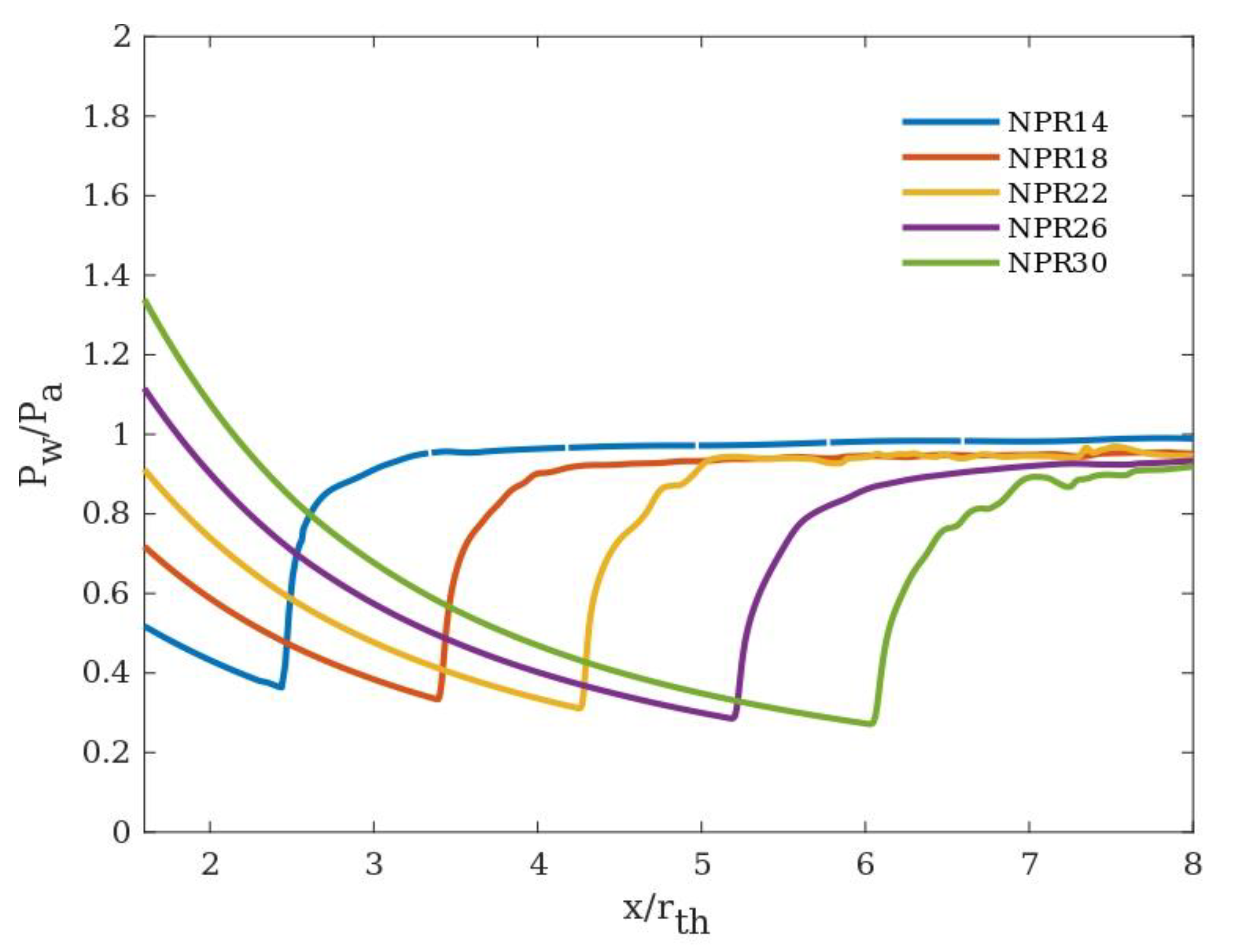
3.1. Effect of Nozzle Pressure Ratio (NPR)

For cold gas flow (300 K), the point of separation was observed to move towards the nozzle exit with every successive NPR (Figure 5). Two different shock patterns were captured for the considered NPR, Mach reflection and cap-shock pattern. Regular Mach reflection with a convex Mach disk was observed for NPR 14 and 22 (Figure 6a,b). Cap shock pattern indicates the onset of transition between free shock separation (FSS) and restricted shock separation (RSS). Momentum imbalance due to cap shock and internal shock caused by the nozzle contour pushes the flow toward the nozzle wall leading to reattachment (RSS). For DLP-PAR, nozzle cap shock was captured for NPR 30 and 40 as shown below in Figure 6c,d. These observations are in line with the studies reported pertaining to transition in this NPR range [13,23].

3.2. Effect of Inlet Temperatures

To study the influence of inlet temperature on the separation, four different pressure ratios (14, 22, 30, and 40) and four inlet temperatures—300 K, 1000 K, 1200 K, and 1500 K (for hydrogen–oxygen propellant)—at adiabatic wall condition were considered. This range of inlet temperature is common for such engines [1]. For a particular NPR, say 14, increasing the inlet temperature resulted in the early occurrence of separation (Figure 7b). This could be attributed to the dependence of temperature on viscosity. The viscosity of the gas increases with an increase in temperature, which in turn affects the boundary layer thickness causing decelerated flow and adverse pressure gradient. The results (in Figure 7a) also indicate the impact of NPR on the delay of separation. For an NPR of 14, the separation is delayed by Xft/Rth = 0.08 when the inlet temperature increases from 300 K to 1000 K. For NPR = 30, the corresponding delay (in separation for the same temperature range) is found to be Xft/Rth = 0.72. The pressure difference between the initialization of separation and the actual occurrence of separation is smaller for higher NPRs.

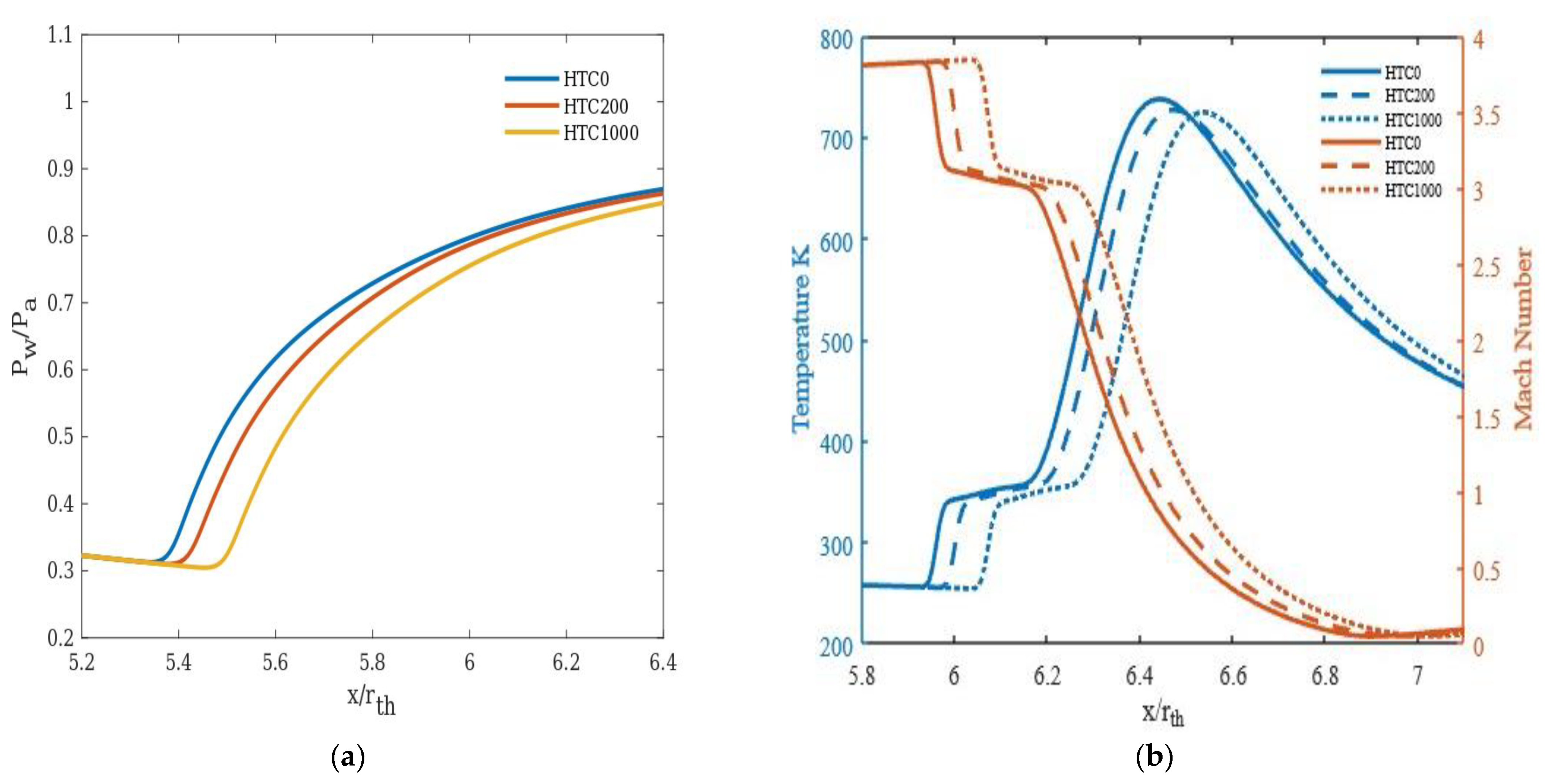
3.3. Effect of Heat Transfer Coefficients

The wall cooling effect in this study has been incorporated by applying convective heat transfer boundary conditions and varying the heat transfer coefficient. Different heat transfer coefficients (0, 200 w/m2K, and 1000 w/m2K) were considered. The inlet temperatures used for the simulations were 1000 K, 1200 K, and 1500 K. A quadratic surface, at a distance y = 0.0015 m, parallel to the nozzle contour was created to study the heat transfer effects on the flow outside the boundary layer.
In general, the convective heat transfer across the wall was found to delay the flow separation. The higher the heat transfer coefficient, the further the separation moves towards the nozzle exit plane (Figure 8a). This could be due to the fact that as the near wall gas temperature decreases due to cooling, its viscosity decreases, leading to a thinner boundary layer. This, in turn, delays the separation. For NPR 22, 30, and 40, the impact on separation is relatively less than NPR 14 (Figure 9a, Figure 10a and Figure 11a).
The heat transfer rate for an area behind the shock emanating at the separation point has been calculated and represented in Table 5. It was observed that the heat transfer rate at and beyond NPR 22 remains almost the same. The saturation of heat transfer could be due to the expansion of the flow at higher NPRs. The temperature difference between HTC 0 and 1000 w/m2K along the quadratic surface is around 20.8% for NPR 14 and around 1 to 2% for other considered NPRs (Figure 8b, Figure 9b, Figure 10b and Figure 11b), justifying the above observation. The drop in Mach number across the region of the shock and the concomitant increase in static temperature are shown in Figure 8b, Figure 9b, Figure 10b and Figure 11b. The minor advancement of the Mach disk towards the exit is shown in Figure 12.
For an inlet temperature of 1200 K, at NPR 14 and NPR 40, the effect of cooling on separation appears to be reduced compared to the same NPR at 1000 K inlet temperature (Figure 13).
For an inlet temperature of 1500 K, cooling has a negligible effect on flow separation for the considered NPRs (Figure 14). Therefore, it could be concluded that for higher inlet gas temperatures, nozzle wall cooling has a lesser impact on flow separation.

4. Conclusions

A numerical investigation was carried out to study the effect of heat transfer on flow separation for a DLP-PAR nozzle. Simulations of shock-induced separation were carried out for a series of operating conditions of practical interest in rocket engines. The influence of nozzle wall cooling on flow separation was examined, and the following are the main findings of the study.
  • Increasing the inlet gas temperature results in early occurrence of separation, and for higher NPRs, the separation occurs much earlier than the lower NPRs, i.e., for NPR 14 the separation was delayed by Xft/Rth = 0.08 and the corresponding delay for NPR 30 was Xft/Rth = 0.72.
  • Wall cooling (modelled in the study by way of heat transfer boundary condition) is found to delay the separation significantly under certain inlet conditions, under which the separation moves towards the nozzle exit plane further with an increase in wall heat transfer. For NPR 14 at an inlet temperature of 1000 K, the separation point moves towards the nozzle exit by 8.8% with cooling and 1.5 to 2.5% for other NPRs.
  • At an inlet temperature of 1000 K, the effect of heat transfer appears to be significant for NPR 14 compared to the other NPRs considered in the study.
  • With an increase in inlet temperature, the effect of heat transfer on flow separation progressively diminishes over the pressure ratios considered.
The findings of the present study contribute to the global body of knowledge in thermal management of rocket nozzles as well as on nozzle performance improvement. An appropriate combination of cooling rate can potentially improve the thrust performance by minimizing the impact of flow separation within the supersonic nozzle.

Author Contributions

Conceptualization, P.M. and A.R.S.; methodology, P.M., A.M. and R.K.V.; software, P.M. and R.K.V.; formal analysis, P.M.; resources, A.M.; writing—original draft preparation, P.M.; writing—review and editing, A.R.S., A.M. and R.K.V.; supervision, A.R.S. and R.K.V. All authors have read and agreed to the published version of the manuscript.

Funding

This research received no external funding and the APC was partially funded by Amrita Vishwa Vidyapeetham.

Data Availability Statement

Not Applicable.

Acknowledgments

Part of the computations was performed on the Aziz supercomputer at KingAbdulaziz University’s High-Performance Computing Center (http://hpc.kau.edu.sa/, accessed on 12 December 2022). The authors acknowledge the computer time and technical support provided by the center.

Conflicts of Interest

The authors declare no conflict of interest.

References

  1. Sutton, G. Rocket Propulsion Elements; John Wiley & Sons: Hoboken, NJ, USA, 1967; Volume 3. [Google Scholar]
  2. Östlund, J.; Damgaard, T.; Frey, M. Side-Load Phenomena in Highly Overexpanded Rocket Nozzles. J. Propuls. Power 2004, 20, 695–704. [Google Scholar] [CrossRef]
  3. Swan, W. The Influence of Nozzle Design on the Flight Performance of Rocket Vechicles with An Analysis of the Results of Jet Separation. Ph.D. Thesis, California Institute of Technology, Pasadena, CA, USA, 1948. [Google Scholar]
  4. Foster, C.R.; Cowles, F.B. Experimental Study of Gas Flow Separation in Overexpanded Exhaust Nozzles for Rocket Motors; Progress Report; Jet Propulsion Laboratory, California Institute of Technology: Pasadena, CA, USA, 1949. [Google Scholar]
  5. Summerfield, M.; Foster, C.R.; Swan, W.C. Flow separation in overexpanded supersonic exhaust nozzles. Jet Propuls. 1954, 24, 319–321. [Google Scholar]
  6. Nave, L.; Coffey, G. Sea level side loads in high-area-ratio rocket engines. In Proceedings of the AIAA/SAE 9th Propulsion Conference, Las Vegas, NV, USA, 5–7 November 1973. [Google Scholar] [CrossRef]
  7. Romine, G.L. Nozzle flow separation. AIAA J. 1998, 36, 1618–1625. [Google Scholar] [CrossRef]
  8. Stark, R.; Hagemann, G. Current status of numerical flow prediction for separated nozzle flows. In Proceedings of the 2nd European Conference for Aerospace Sciences (EUCASS), Brussels, Belgium, 1–6 July 2007. [Google Scholar]
  9. Ostlund, J.; Jaran, M. Assesment of Turbulence Models in Overexpanded Rocket Nozzle Flow Simulations. In Proceedings of the 35th AIAA/ASME/SAE/ASEE Joint Propulsion Conference and Exhibit, Los Angeles, CA, USA, 20–24 June 1999. [Google Scholar]
  10. Nebbache, A.; Pilinski, C. Pulsatory phenomenon in a thrust optimized contour nozzle. Aerosp. Sci. Technol. 2006, 10, 295–308. [Google Scholar] [CrossRef]
  11. Pilinski, C.; Nebbache, A. Flow separation in a truncated ideal contour nozzle. J. Turbul. 2004, 5. [Google Scholar] [CrossRef]
  12. Yonezawa, K.; Morimoto, T.; Tsujimoto, Y.; Watanabe, Y.; Yokota, K. A Study of an Asymmetric Flow in an Overexpanded Rocket Nozzle. J. Fluid Sci. Technol. 2007, 2, 400–409. [Google Scholar] [CrossRef]
  13. Allamaprabhu, Y.; Raghunandan, B.N.; Moríñigo, J.A. Numerical prediction of nozzle flow separation: Issue of turbulence modeling. Aerosp. Sci. Technol. 2016, 50, 31–43. [Google Scholar] [CrossRef]
  14. Lárusson, R.; Andersson, N.; Janöstlund, J. Hybrid RANS-LES Simulation of Separated Nozzle Flow. In Proceedings of the 52nd AIAA/SAE/ASEE Joint Propulsion Conference, Salt Lake City, UT, USA, 25–27 July 2016. [Google Scholar]
  15. Kamali, R.; Mousavi, S.M.; Khojasteh, D. Three-Dimensional Passive and Active Control Methods of Shock Wave Train Physics in a Duct. Int. J. Appl. Mech. 2016, 8. [Google Scholar] [CrossRef]
  16. Chen, C.L.; Chakravarthy, S.R.; Hung, C.M. Numerical investigation of separated nozzle flows. AIAA J. 1994, 32, 1836–1843. [Google Scholar] [CrossRef]
  17. Frey, M.; Hagemann, G. Status of Flow Separation Prediction in Rocket Nozzles. In Proceedings of the 34th AIAA/ASME/SAE/ASEE Joint Propulsion Conference and Exhibit, Cleveland, OH, USA, 13–15 July 1998. [Google Scholar]
  18. Onofri, M.; Nasuti, F.; Nasutit, E. The Physical Origins of Side Loads in Rocket Nozzles. In Proceedings of the 35th AIAA/ASME/SAE/ASEE Joint Propulsion conference and Exhibit, Los Angeles, CA, USA, 20–23 June 1999. [Google Scholar]
  19. Thongsri, J.; Srathonghuam, K.; Boonpan, A. Gas Flow and Ablation of 122 mm Supersonic Rocket Nozzle Investigated by Conjugate Heat Transfer Analysis. Processes 2022, 10, 1823. [Google Scholar] [CrossRef]
  20. Haroon, M.; Rasheed, S.; Irfan, M.; Masud, M.; Munawar, M.A. Computational Investigation of the Flow Structure through an Over-Expanded Nozzle. Eng. Proc. 2022, 23, 7. [Google Scholar] [CrossRef]
  21. Gross, A.; Weiland, C. Numerical simulation of separated cold gas nozzle flows. J. Propuls. Power 2004, 20, 509–519. [Google Scholar] [CrossRef]
  22. Nasuti, F.; Onofri, M. Shock structure in separated nozzle flows. Shock. Waves 2008, 19, 229–237. [Google Scholar] [CrossRef]
  23. Östlund, J.; Muhammad-Klingmann, B. Supersonic flow separation with application to rocket engine nozzles. Appl. Mech. Rev. 2005, 58, 143–177. [Google Scholar] [CrossRef]
  24. Sreejith, K.; Dhrishit, M.; Deepu, M.; Jyachandran, T. Numerical Analysis of Flow Separation in Rocket Nozzles. In Proceedings of the 5th International and 41st National Conference on FMFP, Kanpur, India, 12–14 December 2014; Available online: http://www.springer.com/series/11236 (accessed on 21 September 2016).
  25. Bhide, K.; Siddappaji, K.; Abdallah, S. Influence of fluid–thermal–structural interaction on boundary layer flow in rectangular supersonic nozzles. Aerospace 2018, 5, 33. [Google Scholar] [CrossRef]
  26. Zmijanovic, V.; Rasuo, B.; Chpoun, A. Flow separation modes and side phenomena in an over expanded nozzle. FME Trans. 2012, 40, 111–118. [Google Scholar]
  27. Fouladi, N.; Farahani, M. Numerical investigation of second throat exhaust diffuser performance with thrust optimized parabolic nozzles. Aerosp. Sci. Technol. 2020, 105, 106020. [Google Scholar] [CrossRef]
  28. Ivanov, I.E.; Kryukov, I.A. Numerical study of ways to prevent side loads in an over–expanded rocket nozzles during the launch stage. Acta Astronaut. 2019, 163, 196–201. [Google Scholar] [CrossRef]
  29. Sreerag, V.N.; Mohammad, F.; Nandan, V.; Pramod, A.; Subhajayan, K.P.; Jash, S. Parametric study on a method to control flow separation in rocket nozzles. Mater. Today Proc. 2021, 46, 9950–9955. [Google Scholar] [CrossRef]
  30. Khobragade, N.; Wylie, J.; Gustavsson, J.; Kumar, R. Control of Flow Separation in a Rocket Nozzle Using Microjets. New Space 2019, 7, 31–42. [Google Scholar] [CrossRef]
  31. Hadjadj, A.; Perrot, Y.; Verma, S. Numerical study of shock/boundary layer interaction in supersonic overexpanded nozzles. Aerosp. Sci. Technol. 2015, 42, 158–168. [Google Scholar] [CrossRef]
  32. Verma, M.; Arya, N.; De, A. Investigation of flow characteristics inside a dual bell nozzle with and without film cooling. Aerosp. Sci. Technol. 2020, 99, 105741. [Google Scholar] [CrossRef]
  33. Wang, Z.; Wang, C.; Tian, W. Study on Separation Characteristics of Nozzles with Large Expansion Ratio of Solid Rocket Motors. Aerospace 2022, 10, 4. [Google Scholar] [CrossRef]
  34. Shimura, K.; Asako, Y.; Lee, J.H. Numerical analysis for supersonic flows in a cooled nozzle. Numer. Heat Transfer Part A Appl. 1994, 26, 631–641. [Google Scholar] [CrossRef]
  35. ANSYS. ANSYS Fluent: Theory Guide; Release 2020 R1; ANSYS, Inc.: Canonsburg, PA, USA, 2020. [Google Scholar]
  36. Murugesan, P.; Arjun, B.; Akhil, T.K.; Shashank, P.; Girish, C.C.; Srikrishnan, A.R.; Ratna, K.V. Numerical study of characteristics of underexpanded supersonic jet. J. Aerosp. Technol. Manag. 2020, 12, 1–8. [Google Scholar] [CrossRef]
  37. Sudhan, K.H.; Prasad, G.K.; Kothurkar, N.K.; Srikrishnan, A.R. Studies on supersonic cold spray deposition of microparticles using a bell-type nozzle. Surf. Coat. Technol. 2019, 383, 125244. [Google Scholar] [CrossRef]
  38. Murugu, S.P.; Srikrishnan, A.R.; Krishnaraj, B.K.; Jayaraj, A.; Mohammad, A.; Velamati, R.K. Acoustic Modeling of Compressible Jet from Chevron Nozzle: A Comparison of URANS, LES and DES Models. Symmetry 2022, 14, 1975. [Google Scholar] [CrossRef]
  39. Verma, S.B. Shock unsteadiness in a thrust optimized parabolic nozzle. Shock. Waves 2008, 19, 193–212. [Google Scholar] [CrossRef]
Figure 1. Computational domain and boundary conditions.
Energies 16 01762 g001
Figure 2. Block-structured grid of the DLP-PAR nozzle used for NPR 14.
Energies 16 01762 g002
Figure 3. Wall pressure distribution: (a) at NPR 14 for different viscous models; (b) comparison of simulation result with the experimental result [39] for different NPRs.
Energies 16 01762 g003
Figure 4. Comparison of simulation and experimental [39] separation points (determined based on wall-shear prediction) for different NPRs.
Energies 16 01762 g004
Figure 5. Wall pressure distribution at different NPRs (To = 300 K).
Energies 16 01762 g005
Figure 6. Mach contours for different nozzle pressure ratios: (a) NPR 14 (b) NPR 22 (c) NPR 30 and (d) NPR 40.
Energies 16 01762 g006aEnergies 16 01762 g006b
Figure 7. Wall pressure distribution for different inlet temperatures at (a) different NPRs and (b) NPR 14.
Energies 16 01762 g007
Figure 8. NPR 14 at an inlet temperature of 1000 K for different heat transfer coefficients: (a) Pressure distribution along the nozzle wall, (b) Temperature and Mach number variation at a distance y = 0.0015 m from the nozzle wall.
Energies 16 01762 g008
Figure 9. NPR 22 at an inlet temperature of 1000 K for different heat transfer coefficients: (a) Pressure distribution along the nozzle wall, (b) Temperature and Mach number variation at a distance y = 0.0015 m from the nozzle wall.
Energies 16 01762 g009
Figure 10. NPR 30 at an inlet temperature of 1000 K for different heat transfer coefficients: (a) Pressure distribution along the nozzle wall, (b) Temperature and Mach number variation at a distance y = 0.0015 m from the nozzle wall.
Energies 16 01762 g010
Figure 11. NPR 40 at an inlet temperature of 1000 K for different heat transfer coefficients: (a) Pressure distribution along the nozzle wall, (b) Temperature and Mach number variation at a distance y = 0.0015 m from the nozzle wall.
Energies 16 01762 g011
Figure 12. Represents the movement of Mach disk for NPR14 at HTC 0 and 1000 w/m2K.
Energies 16 01762 g012
Figure 13. Wall pressure distribution at an inlet temperature of 1200 K for different heat transfer coefficients: (a) NPR 14 and (b) NPR 40.
Energies 16 01762 g013
Figure 14. Wall pressure distribution at an inlet temperature of 1500 K for different heat transfer coefficients: (a) NPR 14 and (b) NPR 40.
Energies 16 01762 g014
Table 1. Studies on Numerical simulation of flow separation and wall pressure.
AuthorsTurbulence ModelNozzle ContourRemarks on Validation
Ostlund et al. [9]SSTTOPover prediction for NPR 12 and 16.2
Nebbache et al. [10]SSTTOCover prediction for NPR < 23.9
Pilinski et al. [11]SSTTICunder prediction for NPR < 34.7
over prediction for NPR > 41.3
Yonezawa et al. [12]SST and SACTP (Compressed Truncated Perfect)no differences between the two models, underpredicted
Stark et al. [8]SSTTICUnder prediction for NPR 25
Table 2. Overview of nozzle geometry and boundary conditions considered in the reported literature and the present study.
AuthorsNozzle ContourArea RatioNozzle Inlet Temperature (K)Nozzle Wall Boundary Condition
Ostlund et al. [23]TIC, TOP, TOC, Conical43.4270Adiabatic
Ostlund and Jaran et al. [9]TIC, TOP, Conical45, 43.4270Adiabatic
Nebbache et al. [10]TOC30.32270Adiabatic
Pilinski et al. [11]TIC13.9270Adiabatic
Yonezawa et al. [12]CTP49290Adiabatic
Allamprabhu et al. [13]TOP30270Adiabatic
Laurusson et al. [14]Parabolic nozzle 300Adiabatic
Onofri et al. [18]TOP45300Adiabatic
Gross et al. [21]TIC, TOP, Dual bell13.9, 30300Adiabatic
Nasuti et al. [22]TIC, TOC, TOP 300Adiabatic
Sreejith et al. [24]TIC, TOP and Conical13.9, 30300Adiabatic
Zmijanovic et al. [26]TOC, TOP30.32, 30290Adiabatic
Fouladi et al. [27]TOP60300Adiabatic
Ivanov et al. [28]TOC 293Adiabatic
Sreeraj et al. [29]Bell nozzle30300Solid wall
Khobragade et al. [30]CD nozzle10.74800no heat transfer
Hadjadj et al. [31]TOP, TIC30300Adiabatic
Verma et al. [32]Dual bell 300 and 2842Adiabatic
Wang et al. [33]Laval nozzle30.25Cold flowAdiabatic
Shimura et al. [34]Conical nozzle4.551200wall temperature = 300 K
Present studyTOP30300, 1000, 1200 and 1500Adiabatic and Convective heat transfer (coefficients = 0, 200 and 1000 w/m2K)
Table 3. Grid independence study.
No. of ElementsSeparation Point (X/rth)
198,7502.62
345,8342.437
928,3872.434
Table 4. Boundary conditions.
BoundaryTypeConditions
Nozzle inletPressure inletPo = NPR*Pa; To = 300 K (for cold flow), 1000, 1200 and 1500 K (for hot flow) (NPR = 14, 22, 30 and 40)
Ambient inflowPressure inletPo = 101,325 pa; To = 300 K
Inner wallWall No slip; Adiabatic and convective heat transfer (HTC = 0, 200 and 1000 w/m2K)
Outer wallWall Adiabatic
OutflowPressure outletPa = 101,325 pa
Table 5. Heat transfer rate (in W) calculated for an area behind the shock for inlet temperature = 1000 K.
HTCQ_NPR14Q_NPR22Q_NPR30Q_NPR40
0----
20013.6923.3523.1522.78
100034.55116.6115.76113.88
Disclaimer/Publisher’s Note: The statements, opinions and data contained in all publications are solely those of the individual author(s) and contributor(s) and not of MDPI and/or the editor(s). MDPI and/or the editor(s) disclaim responsibility for any injury to people or property resulting from any ideas, methods, instructions or products referred to in the content.

