1. Introduction
A thermal bridge, or cold bridge, can be defined as a localized zone of a building envelope which has a significantly higher heat transfer when compared to the adjacent areas [
1]. Thermal bridges in buildings, regarding the way they are computed, can be categorized into three types: repeating thermal bridges (e.g., vertical steel studs equally spaced in a LSF wall), linear (nonrepeating) thermal bridges (e.g., along a projecting balcony, a wall-to-wall connection or a wall to floor edges), and point thermal bridges (e.g., the mechanical metallic fasteners to fix the insulation panels in ETICS).
Regarding the origin, there are usually two types of thermal bridges: geometric and construction thermal bridges. An example of a geometric thermal bridge is a wall-to-wall corner, given the higher outer surface area when compared to the inner one. Construction thermal bridges originate from a higher thermal conductivity of a specific localized material, such as a concrete column within a masonry ceramic brick wall.
Thermal bridges may lead to several negative consequences in buildings, such as increased heat transfer through the building envelope, localized colder zones in the inner sheathing surfaces, thermal discomfort of the occupants, moisture and condensation problems, mold growth, and decrease of materials’ durability [
1]. The ASIEPI research project [
2] concluded that “the total impact of thermal bridges on the heating energy need is in general considerable and can be as high as 30%”. Moreover, Ge and Baba [
3] simulated the dynamic effect of thermal bridges on the energy performance of reinforced concrete residential building located in a hot climate and concluded that the presence of thermal bridges is able to increase the annual cooling load by 20%.
Given the high thermal conductivity of steel, the relevance of thermal bridges may be even higher if this issue is not adequately addressed at design stage and their mitigation strategies implemented during construction stage [
4]. This is a very hot research topic, which has been addressed using several approaches, such as in situ or lab measurements [
5,
6,
7], parametric studies [
8,
9,
10], analytical evaluation [
11], and numerical simulations [
4,
7].
Several thermal bridge mitigation strategies in LSF building elements have been developed and studied, including the use of steel profiles having indented flanges [
10], the use of ETICS (external thermal insulation composite systems) [
8,
9,
12,
13], the placement of thermal break strips (TBS) along the steel studs flanges [
5,
6,
7,
9,
10], and the application of steel studs with slotted webs [
9,
14].
There is no perfect thermal mitigation strategy since each one has its inherent drawbacks and advantages. The most frequent thermal bridge mitigation strategy is the use of ETICS. Being a continuous thermal insulation, the thermal performance improvement is more effective. Moreover, the building’s net floor area is not reduced due to the additional ETICS thickness, since it is usually located outside the floor area [
13]. On the other hand, since the very reduced insulation material’s quantity used is placed only where it is needed more, i.e., along the steel stud flanges, the use of TBS is a highly cost-effective strategy to mitigate thermal bridges in LSF walls [
5]. Nevertheless, the use of TBS may have a drawback due to the higher distance between the steel frame and the sheathing panels, equal to the TBS thickness, which will lead to a smaller mechanical resistance to lateral loading shear actions [
15].
The steel stud flanges’ indentation allows a reduction in the contact surface area between the sheathing panels and the steel, thereby reducing the heat transfer across the wall in the vicinity of the steel profile, without increasing the LSF wall thickness [
10]. Moreover, an extra advantage is that the initial flange air gap can be filled with insulation material, similarly to a TBS, but without increasing the LSF wall thickness. Regarding the slotted steel studs strategy, the key disadvantage is related to the reduction in their load-bearing capacity [
10].
In a previous study [
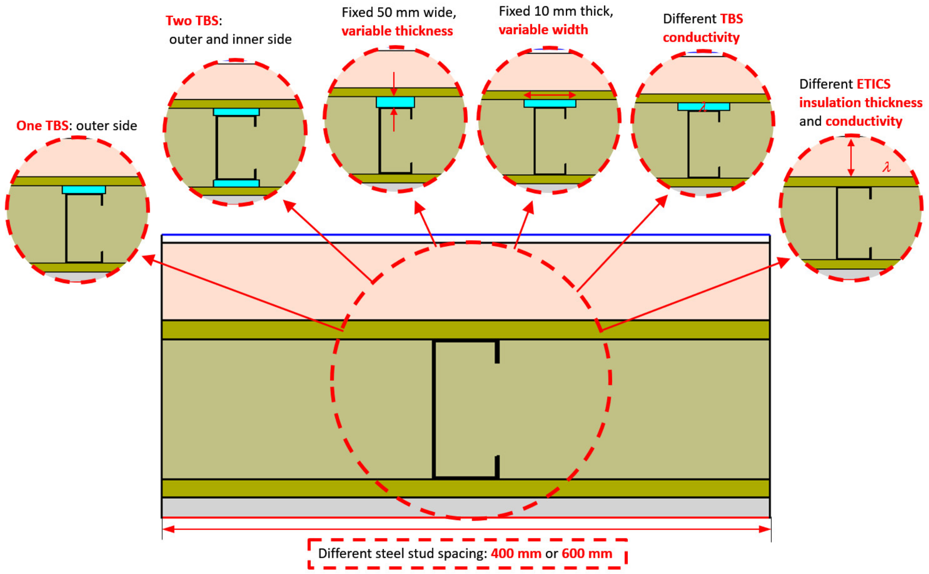
16], the authors performed a parametric study about the use of thermal break strips (TBS) in load-bearing partition LSF walls, to mitigate the steel frame thermal bridges and improve their thermal performance. In this parametric study, five different parameters were assessed: (1) the steel stud distance, (2) the TBS position and number on the steel stud’s flanges, (3) the TBS material’s thermal conductivities, (4) the thicknesses, and (5) the width of TBS cross-section geometry. It was concluded that increasing the TBS width did not always lead to a thermal resistance improvement, and that increasing the TBS thickness is more effective than increasing their width, with this latter conclusion related to the volumetric expansibility of the mineral wool batt insulation.
A similar parametric study for load-bearing facade LSF walls was not found in the literature. Therefore, in the present research, a parametric study is performed for load-bearing facade LSF walls. In addition to the five abovementioned parameters, in the present parametric study, two more parameters are evaluated: (6) the thickness of the ETICS thermal insulation layer, and (7) their thermal conductivity. In this parametric study, bidimensional numerical models were used, which were experimentally validated, and their accuracy was successfully verified using three different additional strategies.
In this paper, after this brief introduction,
Section 2 presents the materials and methods, including a description of the facade LSF wall used as reference, the evaluated parameters and their values, the characterization of the materials, and the numerical simulations. Next, the achieved results are presented and discussed in
Section 3, starting by the reference facade LSF wall, followed by the results for a single TBS and for two TBSs, and finally the results about the relevance of ETICS insulation thickness and their thermal conductivity values. To finalize, the key conclusions of this study are presented in
Section 4.
3. Results and Discussion
In this section, the computed results are displayed and analyzed. First, the -values for the reference facade LSF wall are presented. Then, the thermal performance of this LSF facade wall is evaluated when using a single TBS, placed in the outer steel stud flange. Next, the use of two TBS is assessed. Lastly, the influence of the ETICS insulation thermal conductivity and thickness, when there is no TBS, is also analyzed.
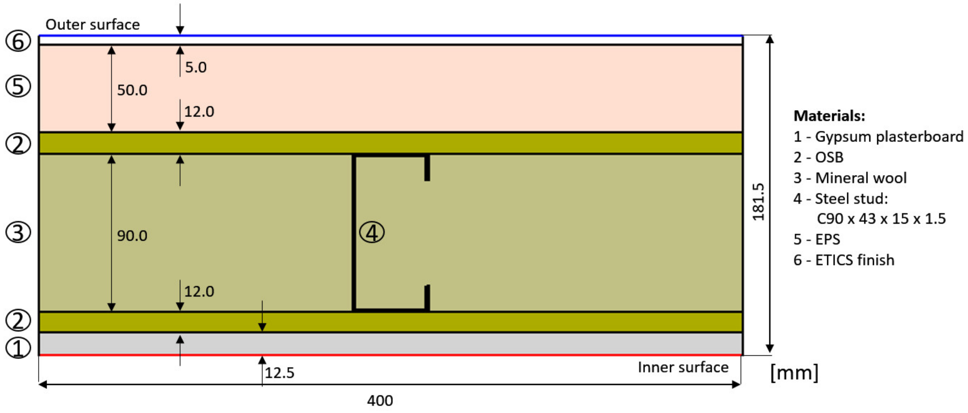
3.1. Reference Facade LSF Wall
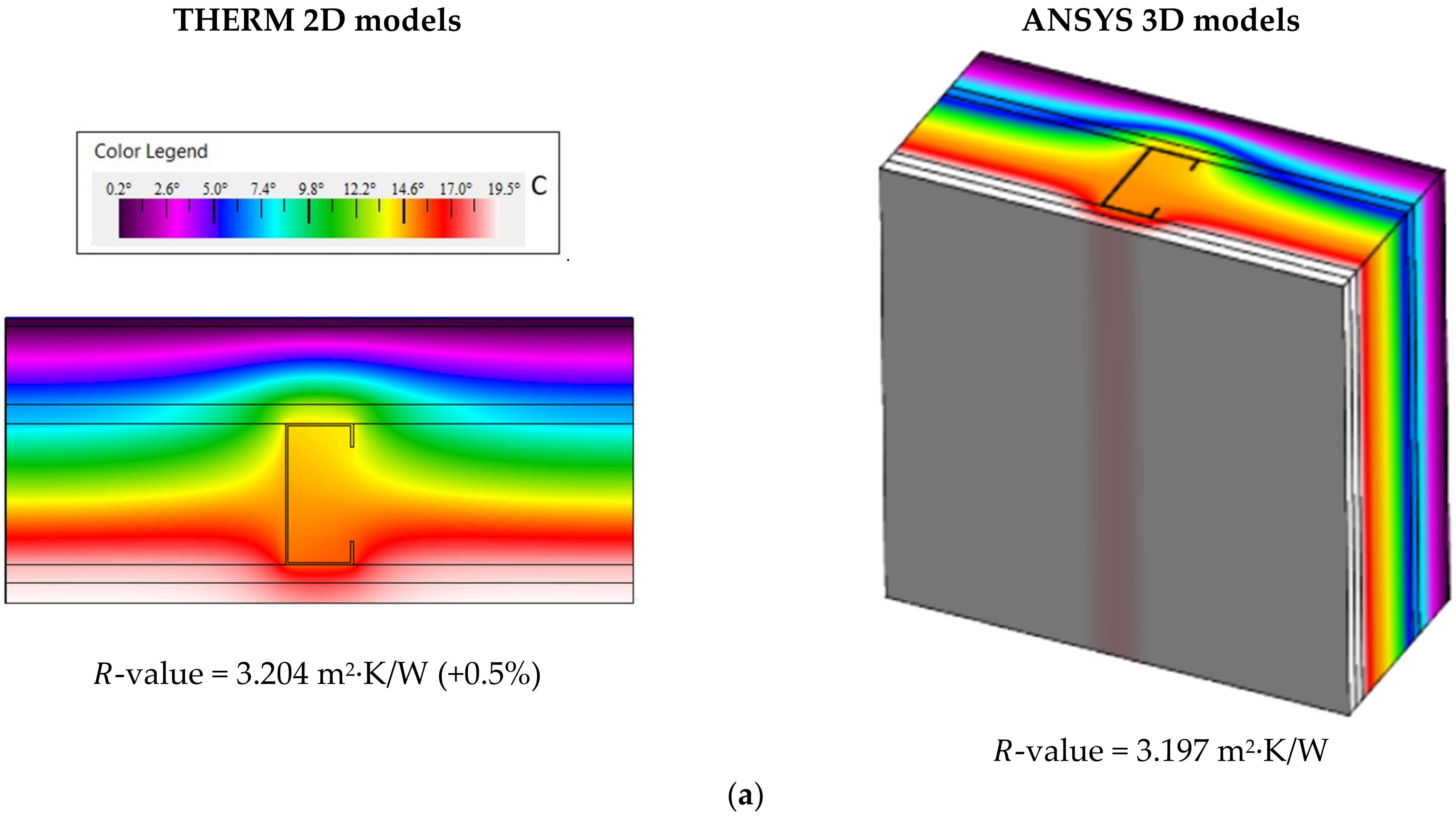
The reference surface-to-surface thermal resistance for the facade LSF wall with commercial C90 × 43 × 15 × 1.5 steel studs, placed 400 mm apart (
Figure 1), is 3.204 m
2∙K/W (
Figure 3a). For the 600 mm steel stud spacing, the 𝑅-value is improved to 3.499 m
2∙K/W (+9%). This thermal performance improvement of the LSF facade wall was expected, due to the decreased amount of steel, originating from the increased steel studs’ spacing.
3.2. One Thermal Break Strip
3.2.1. The Influence of TBS Thickness and Thermal Conductivity
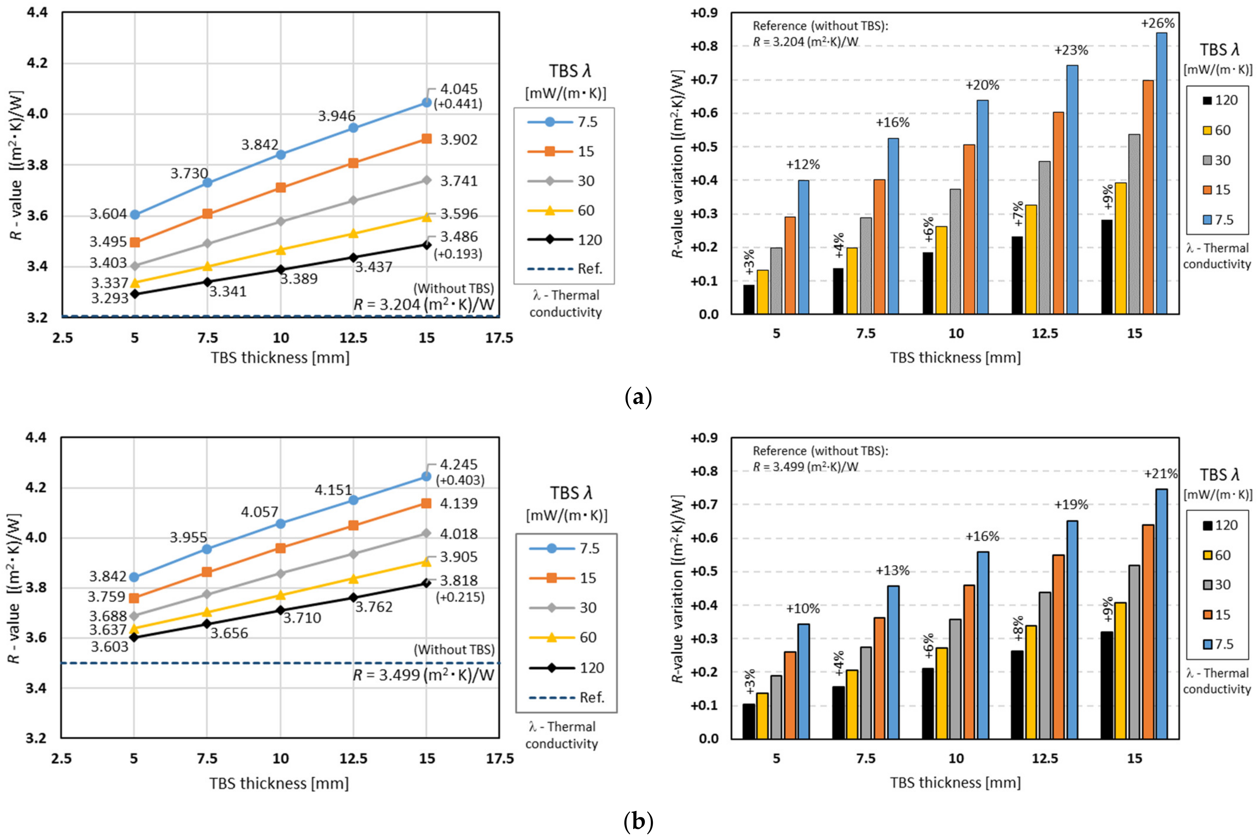
The surface-to-surface thermal resistances obtained for the facade LSF walls, having one TBS with variable thickness and 50 mm width, for two different steel stud spacings ((a) 400 mm; (b) 600 mm), are displayed in
Figure 4. The current charts show the same trend as those described in the previous study [
16], but it can be noted that, on these facade LSF walls (having ETICS), the TBS performance improvement was smaller than in the previous partition LSF walls. This could be explained by the reduced relevance of the steel studs’ thermal bridges due to the ETICS insulation continuous layer.
Nevertheless, with respect to the
-values presented in
Figure 4a for the higher thermal conductivity (120 mW/m·K; black line), even the thinner TBS (5 mm) allowed increasing the thermal performance from 3.204 m
2·K/W (reference value) to 3.293 m
2·K/W. Moreover, when there was an increase in the TBS thickness up to 15 mm, the thermal resistance also had a nearly linear variation increase, up to 3.486 m
2·K/W. In terms of percentages (see right plot), these
-value increments range from +3% to +9%.
Looking now to the other evaluated smaller TBS thermal conductivities, the slope of the corresponding
-values lines also increased with the decrease in TBS conductivity. This trend was predictable, and the major
-values were achieved for the smaller TBS thermal conductivity (7.5 mW/m·K, blue line), varying from 3.604 m
2·K/W (5 mm thick) up to 4.045 m
2·K/W (15 mm thick). As displayed in the right graph of
Figure 4a, this thermal resistance variation, in relation to the reference facade LSF wall, increased from +12% (5 mm thick) to +26% (15 mm thick).
Two analogous plots are displayed in
Figure 4b for 600 mm steel stud spacing, instead of 400 mm spacing. As predicted, all computed
-values were bigger than the preceding ones, including the new reference one (3.449 m
2·K/W). Moreover, for the same TBS thickness, the
-value increase originating from the TBS thermal conductivity decrease was now smaller relatively to the former studs’ spacing (400 mm), illustrated in
Figure 4a.
Additionally, in both plots (400 mm and 600 mm steel studs’ spacing), increasing the TBS thickness always provided an improved thermal performance, regardless of the conductivity. This is due to the assumed mineral wool batt insulation’s volumetric expansibility, fulfilling the increased wall cavity, whereby this wall thickness increment is equal to the TBS thickness.
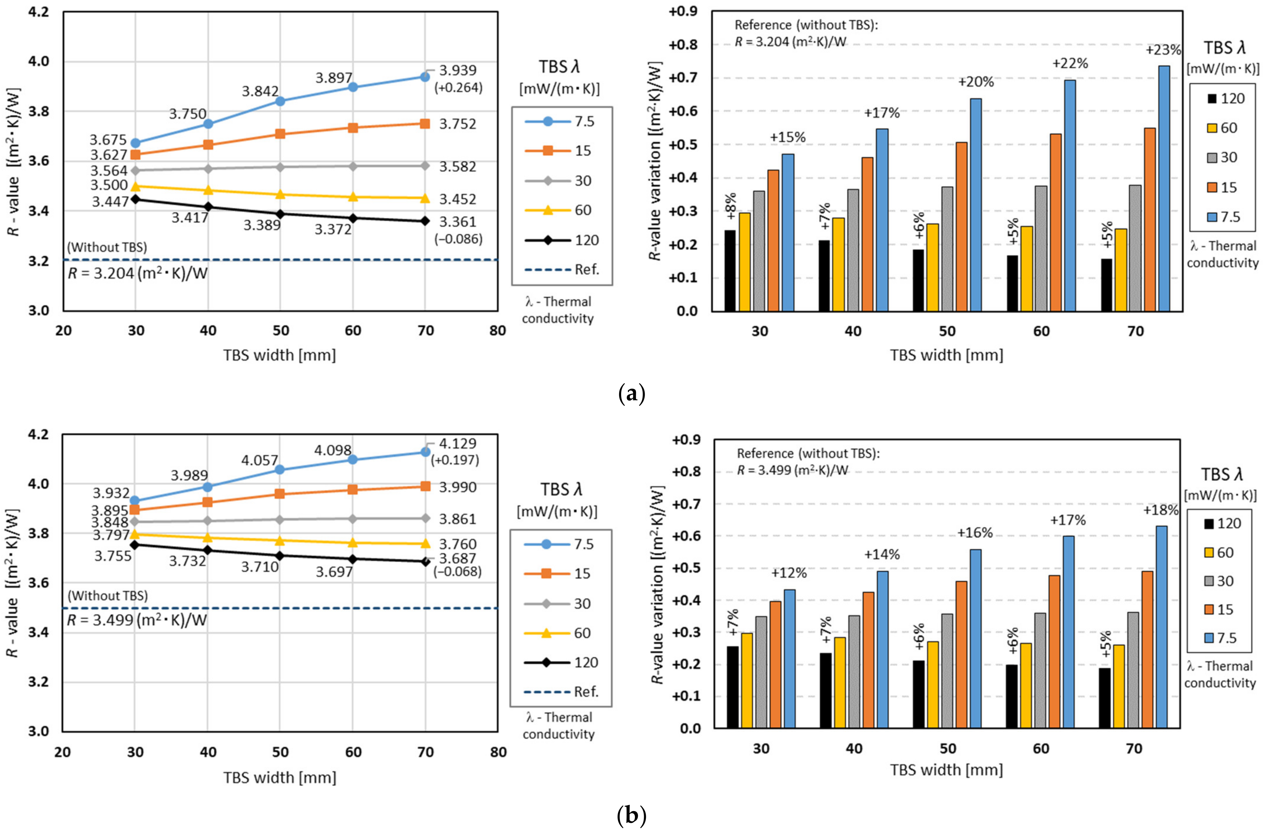
3.2.2. The Influence of TBS Width and Thermal Conductivity
Figure 5a exhibits the surface-to-surface
-values obtained for the facade LSF walls having one TBS with variable width and constant thickness (10 mm), when the steel studs are spaced 400 mm. With respect to the
-values for the thermal conductivity equal to 120 mW/m·K (higher evaluated value; black line), even the smaller assessed TBS width (30 mm) enabled an
-value increase from 3.204 m
2·K/W (reference value) to 3.447 m
2·K/W. However, when the TBS width increased to 70 mm, the
-value decreased to 3.361 m
2·K/W, i.e., a negative variation equal to −0.086 m
2·K/W. Looking now to the thermal conductivity of 30 mW/m·K (gray line), the
-value variation was very reduced (+0.018 m
2·K/W) when increasing the width of the TBS (3.564 to 3.582 m
2·K/W). Observing now the smaller evaluated TBS conductivity
-values (blue line), there was a major increment relative to the reference facade LSF wall (3.204 to 3.675 m
2·K/W), as well as when increasing the TBS width from 30 to 70 mm (+0.264 m
2·K/W). In terms of percentages (see blue vertical bars in the right plot of
Figure 5a), this
-value increment ranged from +15% to +23%.
The computed
-values for a larger steel studs’ spacing (600 mm) are displayed in
Figure 5b. Comparing this new plot with the previous one (
Figure 5a), the major differences are the higher predicted
-values and the reduced thermal performance variations due to the use of TBS. In fact, the
-value reduction for the higher TBS conductivity (120 mW/m·K; black line) became −0.068 m
2·K/W, instead of the previous decrease of −0.086 m
2·K/W. Observing the smaller TBS conductivity (7.5 mW/m·K; blue line), the thermal resistance increment, due to the TBS width increase, became (
Figure 5b, 600 mm) only +0.197 m
2·K/W, when the previous value (
Figure 5a, 400 mm) was +0.264 m
2·K/W.
Comparing
Figure 4 and
Figure 5, it can be observed that a TBS having 10 mm thickness and 30 mm width (
Figure 5) presented higher
-values in comparison to a TBS having 5 mm thickness and 50 mm width (
Figure 4), regardless of the steel studs’ spacing and the TBS conductivity. However, increasing the TBS thickness (
Figure 4) was always more gainful (higher
-values increment) in comparison to a TBS width increase (
Figure 5). Moreover, for the higher evaluated TBS conductivity values (60 and 120 mW/m·K), it was not adequate to increase the TBS width, since there was a consequent reduction in the facade LSF wall thermal performance (
Figure 5). Thus, similarly to a previous study for partition LSF walls [
16], it can also be concluded for facade LSF walls that it is more effective to increase the thickness than the width of the TBS. However, in facade LSF walls, the thermal performance improvement due to the use of TBS was smaller, since the steel studs’ thermal bridges were less relevant, due to the existence of a facade ETICS continuous insulation.
3.3. Two Thermal Break Strips
This subsection presents and discusses the computed -values for facade LSF walls when using two TBS, instead of only one outer TBS.
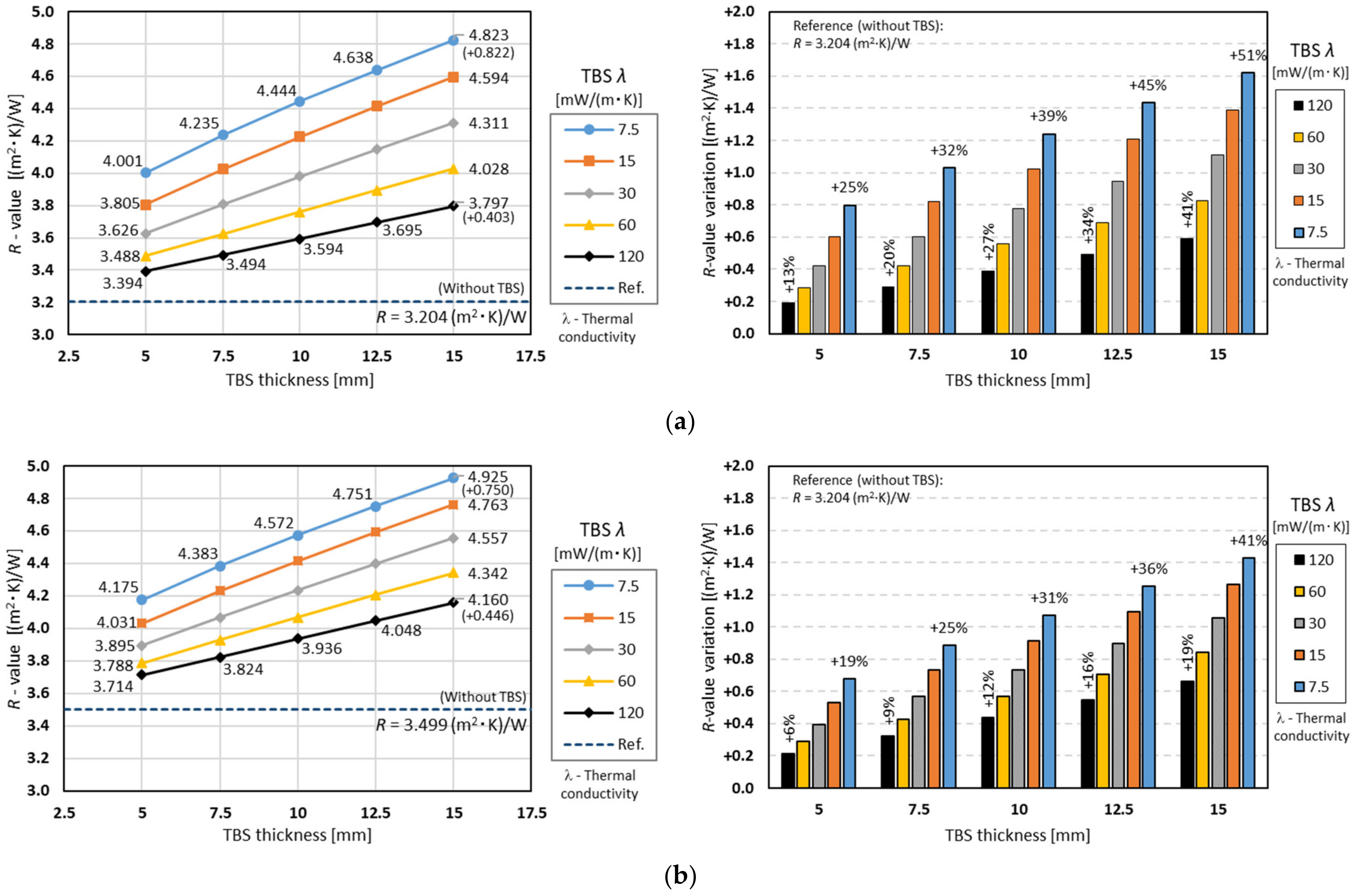
3.3.1. The Influence of TBS Thickness and Thermal Conductivity
Figure 6a is similar to
Figure 4a, but with the facade LSF walls having two TBSs instead of a single outer TBS. These new charts exhibit very similar features to the previous ones but with higher
-values. This was expected given the use of two TBS and their consequent thermal performance improvement. As mentioned before, this thermal performance enhancement was due not only to the use of the TBS itself, but also to the consequent increase in the wall air cavity and batt insulation thickness, which was equal to the thickness summation of both TBSs (10 + 10 mm).
Other interesting findings could be obtained when comparing the case where the total thickness of TBSs was the same, but the number was different (one and two). For example, according to the blue line (λ = 7.5 mW/m·K) in the left graph of
Figure 4a, the
-value was 3.842 [m
2·K)/W when the thickness was 10 mm (one TBS), while, according to the left graph of
Figure 6a, the
-value was 4.001 [(m
2·K)/W] when the thickness of each TBS was 5 mm (the total thickness of two TBSs was 10 mm). This appears to indicate that it is more effective to split the TBSs (higher thermal resistance) instead of using a single one with the same total thickness.
The computed results for a 600 mm steel stud spacing is displayed in
Figure 6b, exhibiting a similar trend to that for a 400 mm spacing (
Figure 6a); however, all obtained
-values were higher than the previous ones, as anticipated given the smaller steel amount per wall square meter and consequent minor steel-related thermal bridge effect. Moreover, in
Figure 6b, for the same TBS thickness, the thermal performance improvement due to the TBS conductivity decrease was now quite smaller when compared to the 400 mm steel stud spacing (
Figure 6a). Additionally, the
-value increment due to the TBS thickness increase was reduced for smaller TBS conductivities (e.g., 7.5 mW/m·K; blue line), +0.750 instead of +0.822 m
2·K/W, and slightly increased for higher thermal conductivity values (e.g., 120 mW/m·K; black line), +0.446 instead of +0.403 m
2·K/W.
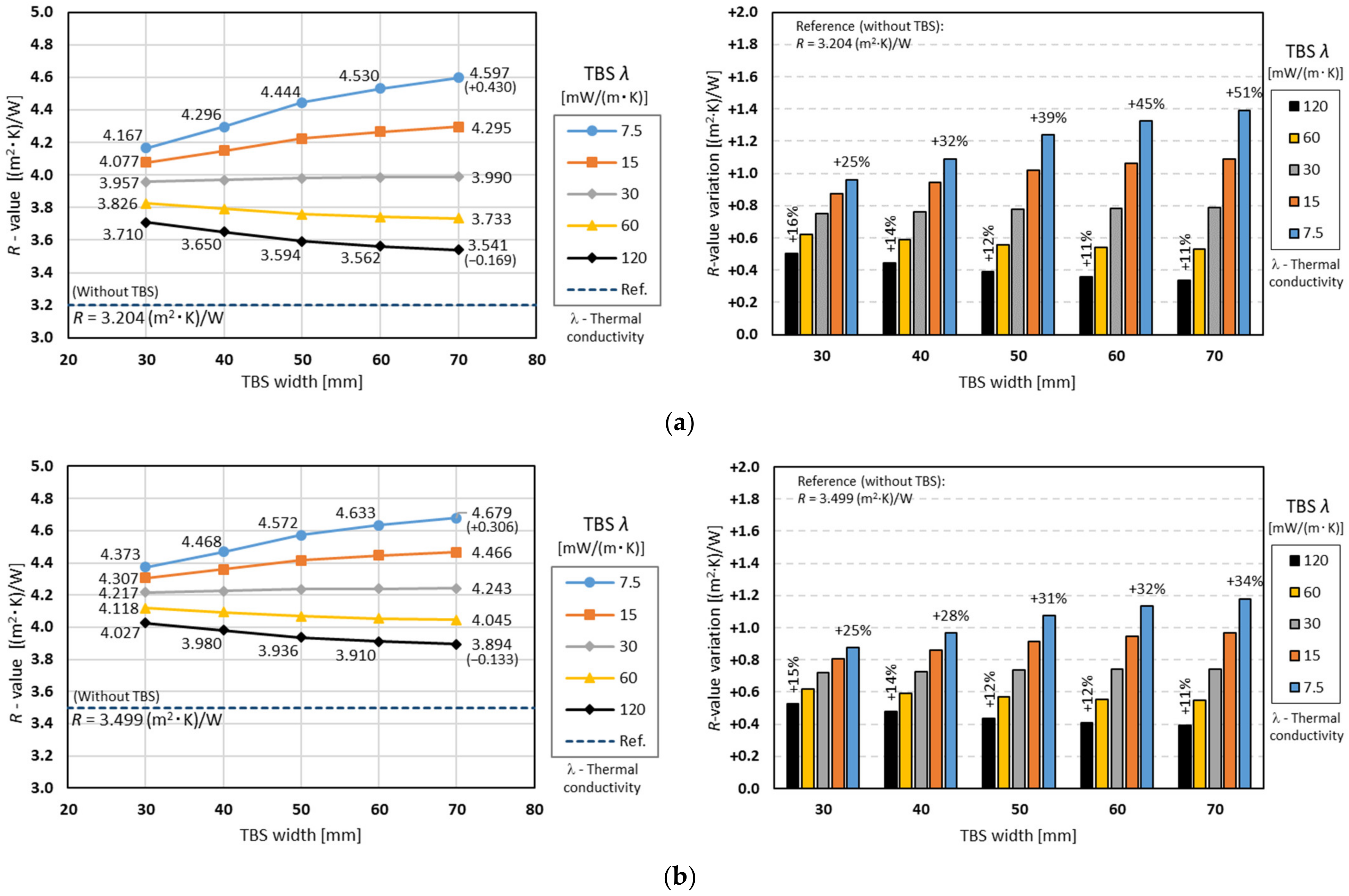
3.3.2. The Influence of TBS Width and Thermal Conductivity
Figure 7a is analogous to
Figure 5a. However, instead of a single outer TBS, the facade LSF walls have two TBSs, i.e., one in the outer stud flange and another TBS in the inner flange. The trends exhibited in these two plots are identical, but with an improved thermal performance, i.e., increased
-values. In addition to this enhanced thermal performance, the relevance of increasing the TBS width was higher for the same TBS conductivity, which was expected since two TBSs were used (
Figure 7a) instead of one (
Figure 5a). In fact, for the smaller TBS conductivity (7.5 mW/m·K; blue line), the
-value increment was +0.430 m
2·K/W, instead of only +0.264 m
2·K/W. Moreover, for the higher evaluated TBS conductivity (120 mW/m·K; black line), the thermal resistance decrease was −0.169 m
2·K/W, instead of −0.086 m
2·K/W.
The predicted
-values for an increased steel stud spacing (600 mm, instead of 400 mm) are plotted in
Figure 7b. As seen before for a single TBS (
Figure 5), this chart had an identical tendency, but now all predicted
-values were bigger when compared to the previous ones (
Figure 7a, 400 mm stud spacing), including the reference one (3.449 m
2·K/W), as mentioned before. Furthermore, the relevance of the TBS conductivity for the same TBS width, and the relevance of the TBS width for the same thermal conductivity were now smaller, when compared to the previous steel stud spacing (400 mm).
3.4. ETICS Insulation Thickness and Thermal Conductivity
In addition to the use of one (see
Section 3.2) or two TBSs (see
Section 3.3), this research assessed the relevance of changing the ETICS insulation thickness and thermal conductivity to improve the thermal performance of facade LSF walls.
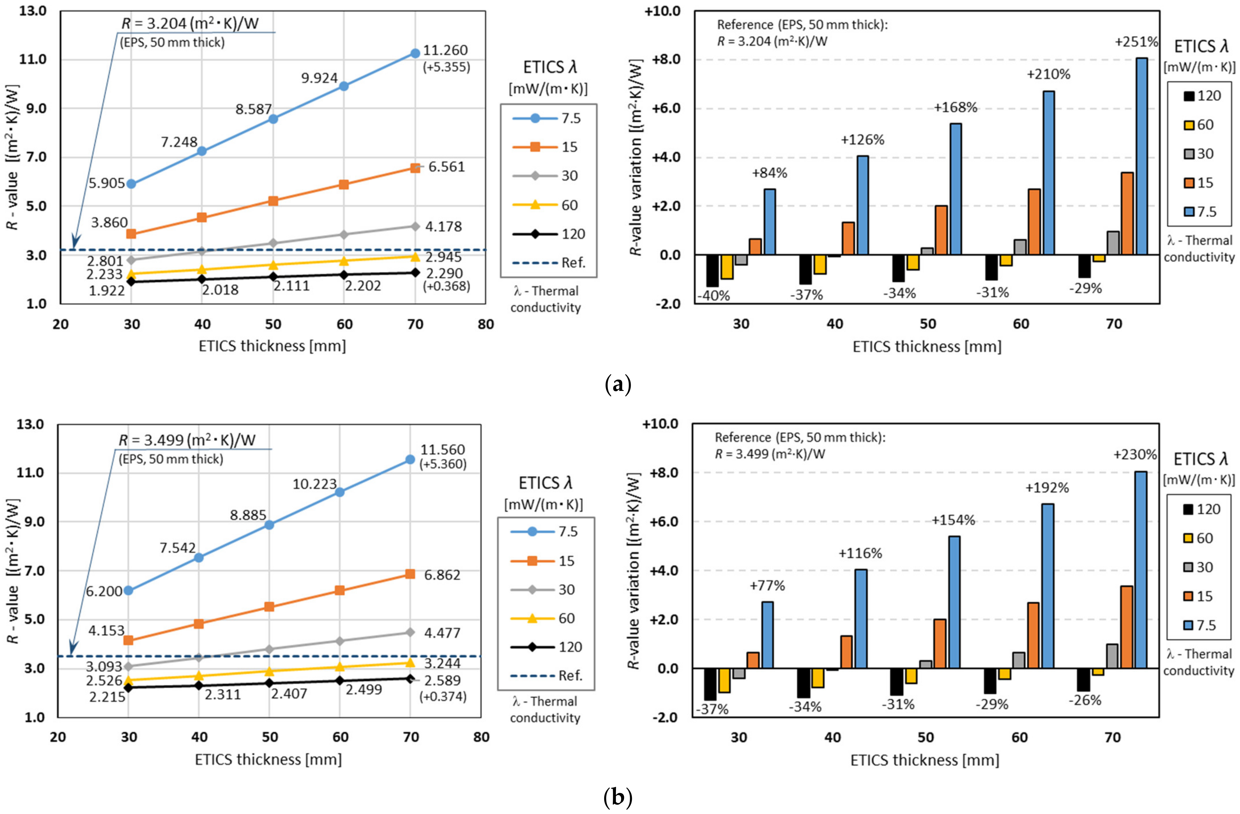
Figure 8a illustrates the computed surface-to-surface
-values, for facade LSF walls having ETICS insulation thickness changing from 30 to 70 mm and thermal conductivity values raging between 7.5 and 120 mW/m·K, with a steel stud spacing equal to 400 mm, without TBS.
Compared to previous plots (one and two TBS), several main differences arise, such as (1) the ETICS insulation thermal conductivity lines for higher values (30, 60 and 120 mW/m·K) having smaller thermal resistances in relation to the reference facade LSF wall -value (3.204 m2·K/W), (2) the -values variation range now being much larger, ranging (70 mm ETICS thickness) from 2.290 m2·K/W up to 11.260 m2·K/W, for the 120 and 7.5 mW/m·K insulation thermal conductivities, respectively, and (3) the thermal resistance increment with the ETICS insulation thickness increase now also being larger, mainly for the smaller thermal conductivities (e.g., +5.360 m2·K/W for 7.5 mW/m·K, blue line).
Figure 8b shows the same parameters variation, but for LSF walls having a 600 mm steel stud spacing. In comparison to the previous steel stud spacing (400 mm) chart (
Figure 8a), the main features are as follows: (1) as expected, due to the minor steel content per LSF wall area, all
-values were now increased; (2) however, the
-value increment due to ETICS insulation thickness increase, for each thermal conductivity value, was very similar (as expected, since this insulation layer was continuous). Note that, in terms of percentages, the
-value increment seemed larger for the 400 mm stud spacing (
Figure 8a, left), but this was mainly due to a smaller reference
-value (3.204 instead of 3.499 m
2·K/W).
As illustrated in
Figure 8b, insulation materials with smaller thermal conductivities, 7.5 and 15 mW/m·K, exhibited higher thermal performance, with maximum
-values (for 70 mm thickness and 600 mm steel stud spacing) of 11.560 and 6.862 (m
2·K)/W, respectively. Not surprisingly, for insulation materials with higher thermal conductivities, 60 and 120 mW/m·K, the
-value of the reference wall (having 50 mm of EPS thermal insulation, 36 mW/m·K) was not reached. Moreover, even for a smaller thermal conductivity (30 mW/m·K; gray line), when the thickness was reduced (30 and 40 mm), the achieved
-values were also smaller than the reference one (3.499 m
2 K)/W).
4. Conclusions
In this article, a parametric study related to the thermal performance of load-bearing facade LSF walls was completed. This research is a continuation of a previous parametric study for partition LSF walls from the same authors [
16]. In the present study, seven parameters were assessed: (1) the steel stud distance; (2) the TBS position and number along the steel stud’s flanges; (3) the thermal conductivity of the TBS material; (4) the TBS thickness; (5) the TBS width; (6) the thickness of the ETICS thermal insulation layer; (7) the thermal conductivity.
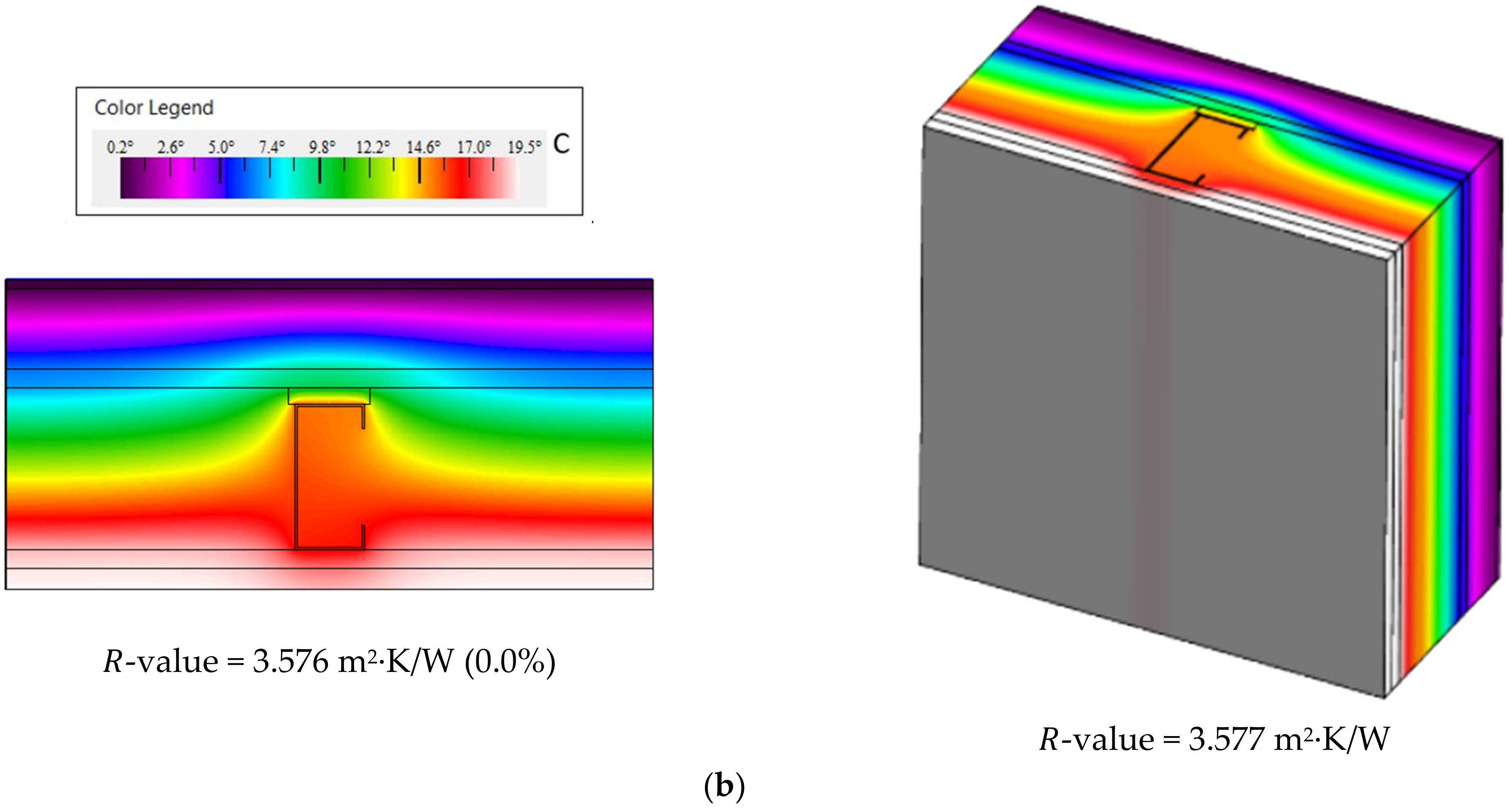
The reliability of the obtained results was ensured by the experimental validation of the bidimensional THERM [
23] models, which were used to simulate the thermal performance of the assessed facade LSF walls. Additionally, their accuracy was also successfully verified using three different approaches.
The main outcomes of this research are summarized as follows:
The increase in the steel stud spacing from 400 mm to 600 mm allowed an
-value thermal performance improvement of +0.295 m
2∙K/W, which is very similar to the result achieved previously for partition LSF walls: +0.292 m
2∙K/W [
16].
Similarly to what was concluded before for load-bearing partition LSF walls [
16], for load-bearing facade LSF walls, it is still more effective to increase the TBS thickness rather than their width.
Nevertheless, the -value increments are slightly smaller for facade LSF walls, due to the existence of an ETICS continuous thermal insulation layer, which decreases the steel studs’ thermal bridges relevance, as expected.
The previous features are valid for one or two TBSs placed along the vertical steel studs, but are more pronounced for the double TBS.
The major thermal performance improvements were found when increasing the ETICS insulation thickness (from 30 to 70 mm) and decreasing their thermal conductivity (to 7.5 mW/m·K), for which it was found a relevant -value increase of +5.360 m2·K/W, for a 400 mm steel stud spacing.
In fact, the abovementioned thermal performance improvement was significantly higher (around 6.5 times) than the most relevant one achieved when using two TBSs, having 15 mm thickness (increased from 5 mm), 50 mm width, and 7.5 mW/m·K thermal conductivity, which was only +0.822 m2·K/W, for the reference steel stud spacing (400 mm).
Regarding the foremost limitations of this study, one can mention that all other steel profiles of the facade LSF wall were neglected, considering only the vertical load-bearing steel studs. Secondly, several batt insulation materials are available on the market, but only one was modeled (mineral wool). With respect to the first constraint, it can be mentioned that the modeled vertical load-bearing steel studs were the most frequent and relevant ones in facade LSF walls. Moreover, some other steel frame profiles (e.g., bottom and top wall trackers) are usually considered within the slab to contribute to the wall linear thermal bridge effect, which was outside of the scope of this study. Concerning the second restriction, mineral wool is perhaps the most used batt insulation material today. Moreover, it was supposed that this fibrous insulation material has enough expandability to fill the cavity of the facade LSF wall.
Through this work, it was possible to better comprehend, compare, and quantify the thermal performance improvement due to the use of TBS and ETICS in load-bearing facade LSF walls. Such a systematic parametric study did not previously exist in the literature. At the design stage, this knowledge could be advantageous for engineers and designers when there is a necessity to specify the TBS material, width, thickness, and number, as well as the ETICS insulation material and thickness.


