Communication

Development of SOFC Interconnects Based on Industrial Steels with Oxide Coating

Institute of Chemistry and Ecology, Vyatka State University, 36 Moskovskaya St., 610000 Kirov, Russia
*
Author to whom correspondence should be addressed.
Energies 2023, 16(3), 1237; https://doi.org/10.3390/en16031237
Submission received: 30 December 2022 / Revised: 17 January 2023 / Accepted: 20 January 2023 / Published: 23 January 2023

Abstract

:
This work suggests a method for obtaining heat-resistant protective coatings for 08Kh17T stainless steel that can be used as interconnect material for solid oxide fuel cells. The suggested approach is based on the layer-by-layer precipitation of nickel, cobalt, and manganese, followed by heat treatment in a vacuum and oxidizing atmosphere. XRD results show that the coatings consist of a mixture of metal oxides and compounds with a spinel structure. The obtained coatings demonstrate high resistance to high-temperature oxidation for 100 h. The coating with the ratio of the thicknesses of the cobalt and manganese layers of 1.5/0.5 μm obtained by electrodeposition is the most stable. The specific electrical resistance of this coating is 3.50·10−3 Ω·cm2 after 100 h of exposure at 850 °C, which meets the requirements for SOFC interconnect materials.

1. Introduction

Recently, significant progress has been made in the development of new energy sources—in particular, solid oxide fuel cells (SOFCs). The necessary condition for the wide use of SOFCs is their stable operation for ~40,000 h without significant degradation. The current collector (interconnector) is one of the critical components of SOFCs that provides its long-term operation. At the same time, the problem of interconnect protection in an oxidizing atmosphere at SOFC operating temperatures has not been solved yet.
Chromium-, nickel-, and iron-based alloys are widely used as interconnect materials owing to suitable thermal expansion coefficients (TECs), the ability to form protective films, and relatively low price. The application of corrosion-resistant alloys and steels, such as Crofer 22 APU [1,2], Sandvik Sanergy HT [3], AISI 441 [4,5], and AISI 430 [6], as SOFC current collectors is complicated. For example, the evaporation of chromium compounds from alloys dramatically affects the long-term stability of the SOFC stack [7,8]. During the SOFC operation, volatile chromium compounds accumulate at the cathode–electrolyte–air three-phase boundary, blocking active centers for oxygen reduction [7]. Moreover, evaporation of chromium from the matrix material promotes oxidation of the interconnector surface and causes changes in the material structure, namely the formation of pores and voids, agglomeration of alloying elements, internal oxidation caused by oxygen diffusion into material volume, and severe corrosion. The combination of all these factors results in SOFC failure [9].
Another reason for SOFC degradation is the interconnect oxidation during operation at temperatures above 800 °C [4,9]. The TEC of the formed oxide layer can mismatch the thermal expansion coefficient of the interconnect material, which causes layer exfoliation; the layer could react with functional ceramic materials. Moreover, layers formed under high-temperature oxidation of corrosion-resistant alloys have high electrical resistance. Currently, the generally accepted upper limit of resistivity for SOFC interconnect materials is 0.1 Ω cm2 [10].
To increase SOFC lifetime, the application of protective coatings is required. Coatings with perovskite or spinel structures based on transition elements (Mn, Co, Cu, Ni, etc.) are believed to be the most promising [6,11,12,13,14,15,16,17,18,19,20]. These coatings have low electrical resistance and act as a barrier for chromium migration to the interconnect surface. Numerous techniques of protective coating application are known, including wet powder spraying [4], physical vapor deposition [21], sol–gel technology [22], electrophoresis [23,24], and electrochemical deposition [17,25,26,27]. Electrochemical deposition seems more promising due to the simplicity and the ability to control the thickness of the coating by varying the electric charge passed through an electrolytic cell.
08Kh17T industrial stainless steel (analog of AISI 439 and AISI 430Ti) coated with a protective electrically conductive layer is a promising material for SOFC interconnects. This steel can be processed easily, has a high corrosion resistance at increased temperatures, and its TEC is 12.8·10−6 K−1 in a temperature range of 20–870 °C [28], which matches the TEC values of ceramic materials used in SOFC design. In addition, this steel is not as expensive as alloys created for SOFC stacking, such as Crofer APU and Sandvik Sanergy HT [12]. However, the corrosion behavior of 08Kh17T industrial stainless steel with a protective coating under SOFC operation conditions has been insufficiently studied.
This work aims to develop the method of deposition of Ni-, Co-, and Mn-based protective coatings onto 08Kh17T heat-resistant steel with a high chromium content and to test the obtained coating under SOFC operating conditions.

2. Materials and Methods

Coating application. A protective coating was applied to the samples of the Fe-Cr stainless steel (08Kh17T) with dimensions of 10 × 5 × 2 mm. The chemical composition of 08Kh17T stainless steel is given in Table 1 [12]. Before coating deposition, the samples were polished, degreased in carbon tetrachloride, and etched in 10% sulfuric acid.
Layer-by-layer electrodeposition of metals was carried out in galvanostatic mode in the following order: an adhesive nickel layer, the main nickel layer, a cobalt layer, and a manganese layer. Table 2 presents compositions of electrolytes and modes of layer deposition.
After the deposition of metals, obtained samples were washed thoroughly with acetone, dried, and heat-treated in a vacuum for 4 h at a temperature of 850 °C to form a Co-Mn alloy. In the second stage, samples were annealed for 5 h at a temperature of 850 °C (a heating rate of 3.3°/min) in an air atmosphere to form oxide compounds.
Cyclic current–voltage curves were recorded in a three-electrode cell using a P-150I (Ellins, Russia) potentiostat/galvanostat. A plate made of the Fe-Cr stainless steel coated with Ni layer acted as the working electrode, a platinum plate was used as the counter electrode, and a silver–silver chloride electrode was used as the reference electrode.
Heat resistance tests. Heat resistance tests were carried out in the following way. Samples of coated Fe-Cr stainless steel were put into crucibles previously fired to a constant mass and weighed. Then, crucibles were put into a muffle furnace and heated to 850 °C with a rate of 13.3°/min in an air atmosphere; samples were weighed after every 5 hours of exposure during the first 25 h of testing. After total exposure for 25 h, the samples were weighed after every 15 h of exposure to the end of the experiment. At the end of each exposure cycle (5 or 15 h), the crucibles were removed from the furnace, cooled in air, and then weighed without removing the samples from the crucibles. The samples were weighed using a VL-324V (Gosmetr, Russia) balance with an accuracy of 0.0001 g. The total time of the tests was 100 hours.
The phase composition of obtained coatings and samples after heat resistance tests was studied at room temperature by X-ray diffraction (XRD) analysis using an XRD-7000 (Shimadzu, Japan) diffractometer with CuKα irradiation (λ = 1.5418 Å) in a 2θ range of 20–80° with a step of 0.02°.
The microstructure of coatings was studied using cross-sections of samples. Coated steel samples were immersed into a cylindrical mold filled with Wood’s alloy; the obtained cylinders were ground with abrasive wheels of various grain sizes and polished using felt wheels with diamond paste. SEM images of the cross-sections were obtained using a JSM-6510LV (JEOL Ltd., Tokyo, Japan) scanning electron microscope with an accelerating voltage of 20 kV.
The resistance of coated steel samples was measured by the four-probe method at direct current [18] using an RM3545-02 (Hioki, Japan) resistance meter. To improve the contact between platinum wire and coating, a platinum paste was applied and burned during the annealing at 850 °C in an argon atmosphere. The measurements were carried out in an air atmosphere at 850 °C for 100 h.

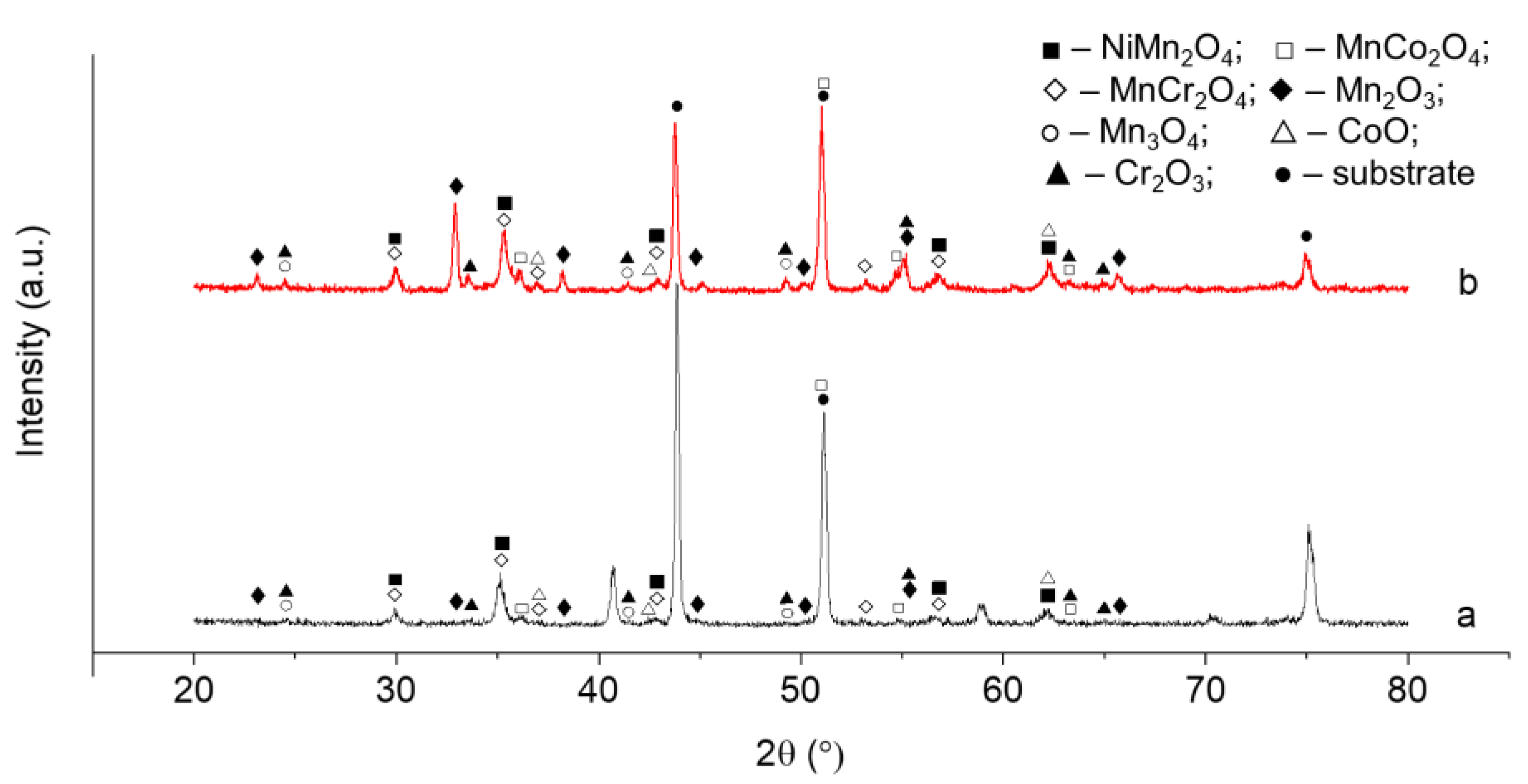
3. Results and Discussion

Coating application. As was shown in [15,18], nickel is a reliable barrier to prevent chromium evaporation. Moreover, the nickel sublayer improves the adhesion of Co-Mn coating to the interconnect metal [29]. Therefore, before the deposition of cobalt and manganese, two-stage nickel deposition was performed to obtain adhesive and main layers. The adhesive layer was deposited from an electrolyte with a high concentration of hydrochloric acid, which made it possible to remove traces of oxides from the surface of stainless steel. The main nickel layer was obtained from the Watts electrolyte [30].
To determine whether co-electrodeposition of cobalt and manganese is possible, cyclic current–voltage curves were obtained for aqueous solutions containing ions of the corresponding metals (Figure 1a).
As seen in Figure 1a, the potential difference between the cobalt and manganese deposition is 480 mV. Therefore, cobalt and manganese cannot be simultaneously deposited from this solution.
As mentioned in some studies [11,17], the addition of complexing agents causes shifting of the metal reduction potentials at the cathode that promotes the co-electrodeposition of cobalt and manganese. However, the introduction of dimethyl sulfoxide (DMSO) as a complexing agent into the electrolyte only leads to an increase in the difference in the reduction potentials of Co and Mn up to 540 mV (Figure 1b).
Thus, the values of the reduction potentials of cobalt and nickel were not close enough for co-electrodeposition. Besides, it is difficult to control the composition of an obtained alloy at the co-electrodeposition of two metals. Therefore, electrodeposition was carried out in two stages: first, a coating with cobalt was obtained from an electrolyte containing Co2+ ions, and then a metallic manganese coating was deposited from an electrolyte containing Mn2+ ions. To determine an optimal coating thickness and Mn/Co ratio, the amount of electricity passed through the electrolytic cell was varied to obtain different δCo/δMn ratios (where δCo and δMn are thicknesses of layers obtained by electrodeposition of cobalt and manganese, respectively) (Table 3).
Obtained metallic coatings were subsequently heat-treated in a vacuum and oxidizing atmosphere at 850 °C to form the protective coating.
Figure 2 presents EDX results of element distribution over the coating thickness in different stages of the protective coating formation. After the electrodeposition of nickel, manganese, and cobalt, there are clear boundaries between deposited layers (Figure 2a,b). Since manganese has high chemical activity, a small peak in the oxygen distribution profile (Figure 2b) is observed due to the surface oxidation of manganese after electrodeposition.
During vacuum and oxidizing annealing, element diffusion occurs that results in coating homogenization (Figure 2c,d). It is seen in Figure 2d that a thin layer enriched with Cr and O was formed at the steel–coating interface. In our opinion, the appearance of this layer is connected with the formation of the Cr2O3 scale [12,16], which is confirmed by XRD data given in Figure 3. Similar phases were obtained after the deposition of protective coatings on stainless steels [11,31,32] and Ni-containing alloys [28] by different methods. In addition, the oxygen-free interdiffusion layer consisting of Fe, Ni, Co, and Cr was formed; its width was ~25 µm.
XRD data given in Figure 3 indicate that the coating consists of a mixture of manganese, cobalt, and nickel oxides (NiMn2O4, MnCo2O4, and MnCr2O4) formed during oxidizing annealing. Thus, the layer-by-layer electrodeposition of nickel, cobalt, and manganese, followed by vacuum and oxidizing annealing, makes it possible to form a coating containing phases with a spinel structure.
Heat resistance test. Figure 4 presents kinetic oxidation curves of coated samples and bare Cr-Fe stainless steel.
As seen in Figure 4a, the corrosion rate of bare steel is higher than for the coated samples, and no plateau is observed in the dependence of sample weight on the time of the heat resistance test. Samples with the δCo/δMn ratio of 1.5/0.5 µm possessed the highest heat resistance (Figure 4a, curve 5) that demonstrates negligible changes in sample weight after 40 h of exposure. As for coatings with other δCo/δMn ratios, the sample weight increases during the whole experiment, which is caused by oxidation. This is explained by the fact that coatings with smaller thicknesses are porous and the corrosion process continues in the pores [16]. On the other hand, while the total thickness of the coating exceeds 4 μm, large internal stresses arise and the coating is exfoliated [33].
The weight of samples increases with the exposure time according to the parabolic law of the reaction rate [34]:
m S 2 = k p · t ,
where Δm is an average sample weight gain, g; S is the surface area of the sample, cm2; t is the annealing time, s; kp is a rate constant, g2·cm−4·s−1. The values of the oxidation rate constants are presented in Table 4.
As seen in Table 4, the application of coating onto the surface of 08Kh17T stainless steel reduces the oxidation rate by 2–5 times, similarly to coatings applied to AISI 430 [35], Sanergy HT [36], Crofer 22 APU, Crofer 22 H, and E-Brite [37] steels and alloys.
Figure 5 presents SEM images of cross-sections of Fe-Cr steel samples with protective coating after heat resistance tests.
It is seen in Figure 5a,b that the coating thickness increases with the growth of exposure time to 50 h. Such growth is explained by the reaction of oxygen with coating components. However, the thickness of the coating is almost unchanged after 100 h of exposure in oxidizing atmosphere (Figure 5c); no formation of cracks or pores is observed.
According to data given in Figure 6a,b, the reaction between manganese and chromium oxides formed after oxidizing annealing (Figure 2d) occurs during 100 h of exposure and results in the formation of a coating containing Cr, O, and Mn that can be attributed to the MnCr2O4 phase (Figure 7). The width of the diffusion layer observed after oxidizing annealing and formed by Ni, Co, Fe, and Cr reaches ~40 µm. It might be suggested that this layer is formed due to the diffusion of deposited Ni and Co into the stainless steel; however, some additional experiments which are beyond the scope of this work are required to explain this phenomenon.
As shown in Figure 7, there is an increase in the content of chromium oxide and NiMn2O4 and MnCo2O4 phases during oxidizing annealing. Moreover, manganese diffusion into the chromium oxide layer occurs [38], leading to the formation of a thermodynamically stable MnCr2O4 phase [39]. The content of this phase increases with the oxidation time similarly to the formation of a reactive MnCr2O4 layer consisting of Cr2O3 in the case of AISI 430 [6] and AISI 441 [40] steels during oxidizing annealing.
Thus, the obtained coatings demonstrated high heat resistance during exposure for 100 h at 850 °C. The best protective properties were demonstrated by the coating with the ratio of electrodeposited cobalt and manganese layers δCo/δMn of 1.5/0.5 µm.
Electrical resistance of the coating. Electrical resistance measured by the four-probe method includes the resistance of both coating and interconnect steel. Since the electrical resistance of the steel is negligible compared with the coating, the measured electrical resistance of the samples was attributed to the coating. The resistivity of the coated steel sample (δCo/δMn = 1.5/0.5 µm) was measured at a temperature of 850 °C, which corresponds to the average operating temperature of SOFC.
Figure 4b presents the dependence of the electrical resistance of the coated Fe-Cr steel sample on the exposure time. As is seen, the resistivity of the sample slightly increases from 3.36 to 3.50·10–3·Ω·cm2, which might be explained by the coarsening of the coating microstructure, leading to the degradation of the electrical contact [12]. Comparable electrical resistivity values were obtained for similar coatings deposited to chromium steels and alloys E-Brite [41], AISI 430 [42], and Crofer 22 APU [32,43] and nickel alloys 33NK and 47ND [28].
Thus, the method of layer-by-layer electrodeposition of nickel, cobalt, and manganese makes it possible to obtain heat-resistant coatings having significantly lower specific electrical resistance than the upper limit of the specific resistance of interconnectors of 0.1·Ω·cm2 [10].

4. Conclusions

The method was developed for applying a protective coating to 08Kh17T stainless steel using layer-by-layer electrodeposition of nickel, cobalt, and manganese from aqueous electrolytes followed by heat treatment in a vacuum and oxidizing atmosphere.
According to the phase composition analysis, the coating mainly consists of oxides of deposited metals and compounds with a spinel structure.
The study of thermal stability showed that the best resistance to high-temperature oxidation is demonstrated by the coating with the ratio of Co/Mn metal layers of 1.5/0.5 µm.
The electrical resistivity of the coating does not exceed 3.50·10−3·Ω·cm2 and remains almost the same over 100 h of exposure in an air atmosphere at a temperature of 850 °C, which proves the stability of the coating.
According to the obtained results, 08Kh17T industrial steel covered with Ni-Co-Mn protective coating has prospects for application as a metallic interconnect for solid oxide fuel cells.

Author Contributions

Conceptualization, O.E. and A.K.; methodology, O.E and A.B.; validation, A.K.; formal analysis, O.E. and N.S.; investigation, A.B., I.T., M.B. and Y.C.; data curation, A.B.; writing—original draft preparation, O.E.; writing—review and editing, N.S. and O.E.; visualization, I.T.; supervision, A.K. All authors have read and agreed to the published version of the manuscript.

Funding

This work was supported by National Technology Initiative Fund.

Data Availability Statement

The data presented in this study are unavailable due to the limitations set by the work funder.

Acknowledgments

The authors are grateful to V. Vorotnikov, A. Chernyad’ev, and B. Ananchenko for their assistance with the experiment.

Conflicts of Interest

The authors declare no conflict of interest.

References

  1. Wu, J.; Liu, X. Recent Development of SOFC Metallic Interconnect. J. Mater. Sci. Technol. 2010, 26, 293–305. [Google Scholar] [CrossRef]
  2. Piccardo, P.; Spotorno, R.; Geipel, C. Investigation of a Metallic Interconnect Extracted from an SOFC Stack after 40,000 h of Operation. Energies 2022, 15, 3548. [Google Scholar] [CrossRef]
  3. Skilbred, A.W.B.; Haugsrud, R. Sandvik Sanergy HT—A Potential Interconnect Material for LaNbO4-Based Proton Ceramic Fuel Cells. J. Power Sources 2012, 206, 70–76. [Google Scholar] [CrossRef] [Green Version]
  4. Bianco, M.; Ouweltjes, J.P.; Van herle, J. Degradation Analysis of Commercial Interconnect Materials for Solid Oxide Fuel Cells in Stacks Operated up to 18000 Hours. Int. J. Hydrogen Energy 2019, 44, 31406–31422. [Google Scholar] [CrossRef]
  5. Jablonski, P.D.; Cowen, C.J.; Sears, J.S. Exploration of Alloy 441 Chemistry for Solid Oxide Fuel Cell Interconnect Application. J. Power Sources 2010, 195, 813–820. [Google Scholar] [CrossRef]
  6. Ebrahimifar, H.; Zandrahimi, M. Mn Coating on AISI 430 Ferritic Stainless Steel by Pack Cementation Method for SOFC Interconnect Applications. Solid State Ion. 2011, 183, 71–79. [Google Scholar] [CrossRef]
  7. Mah, J.C.W.; Muchtar, A.; Somalu, M.R.; Ghazali, M.J. Metallic Interconnects for Solid Oxide Fuel Cell: A Review on Protective Coating and Deposition Techniques. Int. J. Hydrogen Energy 2017, 42, 9219–9229. [Google Scholar] [CrossRef]
  8. Spotorno, R.; Paravidino, D.; Delsante, S.; Piccardo, P. Volatilization of Chromium from AISI 441 Stainless Steel: Time and Temperature Dependence. Surf. Coat. Technol. 2022, 433, 128125. [Google Scholar] [CrossRef]
  9. Singheiser, L.; Huczkowski, P.; Markus, T.; Quadakkers, W.J. 1.19—High Temperature Corrosion Issues for Metallic Materials in Solid Oxide Fuel Cells. In Shreir’s Corrosion; Cottis, B., Graham, M., Lindsay, R., Lyon, S., Richardson, T., Scantlebury, D., Stott, H., Eds.; Elsevier: Oxford, UK, 2010; pp. 482–517. ISBN 978-0-444-52787-5. [Google Scholar]
  10. Zhu, W.Z.; Deevi, S.C. Development of Interconnect Materials for Solid Oxide Fuel Cells. Mater. Sci. Eng. A 2003, 348, 227–243. [Google Scholar] [CrossRef]
  11. Zhang, H.H.; Zeng, C.L. Preparation and Performances of Co–Mn Spinel Coating on a Ferritic Stainless Steel Interconnect Material for Solid Oxide Fuel Cell Application. J. Power Sources 2014, 252, 122–129. [Google Scholar] [CrossRef]
  12. Ananyev, M.V.; Solodyankin, A.A.; Eremin, V.A.; Farlenkov, A.S.; Khodimchuk, A.V.; Fetisov, A.V.; Chernik, A.A.; Yaskelychik, V.V.; Ostanina, T.N.; Zaikov, Y.P. Protective Coatings La–Mn–Cu–O for Stainless-Steel Interconnector 08X17T for SOFC, Obtained by the Electrocrystallization Method from Non-Aqueous Solutions. Russ. J. Non-Ferr. Metals 2018, 59, 102–110. [Google Scholar] [CrossRef]
  13. Ranjbar-Nouri, Z.; Soltanieh, M.; Rastegari, S. Applying the Protective CuMn2O4 Spinel Coating on AISI-430 Ferritic Stainless Steel Used as Solid Oxide Fuel Cell Interconnects. Surf. Coat. Technol. 2018, 334, 365–372. [Google Scholar] [CrossRef]
  14. Wei, P.; Bateni, M.R.; Petric, A. Conversion of Copper and Manganese Metallic Films to Spinel Coating. J. Mater. Sci. 2012, 47, 5205–5215. [Google Scholar] [CrossRef]
  15. Geng, S.; Qi, S.; Zhao, Q.; Zhu, S.; Wang, F. Electroplated Ni–Fe2O3 Composite Coating for Solid Oxide Fuel Cell Interconnect Application. Int. J. Hydrogen Energy 2012, 37, 10850–10856. [Google Scholar] [CrossRef]
  16. Pan, Y.; Geng, S.; Chen, G.; Wang, F. CuFe2O4/CuO Coating for Solid Oxide Fuel Cell Steel Interconnects. Int. J. Hydrogen Energy 2021, 46, 22942–22955. [Google Scholar] [CrossRef]
  17. Pinto, R.; Carmezim, M.J.; Montemor, M.F. Electrodeposition and Isothermal Aging of Co and Mn Layers on Stainless Steel for Interconnectors: Initial Stages of Spinel Phase Formation. J. Power Sources 2014, 255, 251–259. [Google Scholar] [CrossRef]
  18. Geng, S.; Li, Y.; Ma, Z.; Wang, L.; Li, L.; Wang, F. Evaluation of Electrodeposited Fe–Ni Alloy on Ferritic Stainless Steel Solid Oxide Fuel Cell Interconnect. J. Power Sources 2010, 195, 3256–3260. [Google Scholar] [CrossRef]
  19. Zhu, J.H.; Chesson, D.A.; Yu, Y.T. Review—(Mn,Co)3O4-Based Spinels for SOFC Interconnect Coating Application. J. Electrochem. Soc. 2021, 168, 114519. [Google Scholar] [CrossRef]
  20. Yang, Z.; Xia, G.; Simner, S.P.; Stevenson, J.W. Thermal Growth and Performance of Manganese Cobaltite Spinel Protection Layers on Ferritic Stainless Steel SOFC Interconnects. J. Electrochem. Soc. 2005, 152, A1896. [Google Scholar] [CrossRef]
  21. Bianco, M.; Caliandro, P.; Diethelm, S.; Yang, S.; Dellai, A.; Van herle, J.; Steinberger-Wilckens, R. In-Situ Experimental Benchmarking of Solid Oxide Fuel Cell Metal Interconnect Solutions. J. Power Sources 2020, 461, 228163. [Google Scholar] [CrossRef]
  22. Shen, Z.; Rong, J.; Yu, X. MnxCo3-XO4 Spinel Coatings: Controlled Synthesis and High Temperature Oxidation Resistance Behavior. Ceram. Int. 2020, 46, 5821–5827. [Google Scholar] [CrossRef]
  23. Si, X.; Wang, D.; Li, C.; Qi, J.; Cao, J. Exploring the Role of Mn–Co Spinel Coating on Crofer 22 APU in Adjusting Reactions with the Ag Based Sealant during Reactive Air Brazing. J. Mater. Res. Technol. 2022, 16, 608–618. [Google Scholar] [CrossRef]
  24. Sabato, A.G.; Zanchi, E.; Molin, S.; Cempura, G.; Javed, H.; Herbrig, K.; Walter, C.; Boccaccini, A.R.; Smeacetto, F. Mn-Co Spinel Coatings on Crofer 22 APU by Electrophoretic Deposition: Up Scaling, Performance in SOFC Stack at 850 °C and Compositional Modifications. J. Eur. Ceram. Soc. 2021, 41, 4496–4504. [Google Scholar] [CrossRef]
  25. Gong, J.; Zangari, G. Electrodeposition and Characterization of Manganese Coatings. J. Electrochem. Soc. 2002, 149, C209. [Google Scholar] [CrossRef]
  26. Cetina-Dorantes, M.; Lizama-Tzec, F.I.; Estrella-Gutiérrez, M.A.; Herrera-Zamora, D.M.; Arés-Muzio, O.; Oskam, G. Electrodeposition of Cobalt-Manganese Oxide Selective Coatings for Solar-Thermal Applications. Electrochim. Acta 2021, 391, 138906. [Google Scholar] [CrossRef]
  27. Joshi, S.; Petric, A. Nickel Substituted CuMn2O4 Spinel Coatings for Solid Oxide Fuel Cell Interconnects. Int. J. Hydrogen Energy 2017, 42, 5584–5589. [Google Scholar] [CrossRef]
  28. Eremin, V.A.; Solodyankin, A.A.; Belyakov, S.A.; Khodimchuk, A.V.; Farlenkov, A.S.; Krainova, D.A.; Saetova, N.S.; Kuzmin, A.V.; Artamonov, A.S.; Steinberger-Wilckens, R.; et al. Formation of Conductive Oxide Scale on 33NK and 47ND Interconnector Alloys for Solid Oxide Fuel Cells. Energies 2019, 12, 4795. [Google Scholar] [CrossRef] [Green Version]
  29. Kale, V.N.; Kumaraguru, S.; Saravanan, G.; Jalaluddeen, A.S.; Rajkumar, P.; Subadevi, R.; Sivakumar, M.; Gnanamuthu, R.M. Influence of Nickel Strike as Adhesive Layer on Electrodeposited Zn-Co-Ni Alloy and Their Performance in Metal-Finishing. Mater. Today Proc. 2021, 40, S248–S253. [Google Scholar] [CrossRef]
  30. Yavuz, A.; Ozdemir, N.; Yilmaz Erdogan, P.; Zengin, H.; Zengin, G.; Bedir, M. Effect of Electrodeposition Potential and Time for Nickel Film Generation from Ionic Liquid Electrolytes for Asymmetric Supercapacitor Production. Thin Solid Film. 2020, 711, 138309. [Google Scholar] [CrossRef]
  31. Bateni, M.R.; Wei, P.; Deng, X.; Petric, A. Spinel Coatings for UNS 430 Stainless Steel Interconnects. Surf. Coat. Technol. 2007, 201, 4677–4684. [Google Scholar] [CrossRef]
  32. Ebrahimifar, H.; Zandrahimi, M. Oxidation and Electrical Behavior of Mn-Co-Coated Crofer 22 APU Steel Produced by a Pack Cementation Method for SOFC Interconnect Applications. Oxid Met 2015, 84, 129–149. [Google Scholar] [CrossRef]
  33. Shong, W.-J.; Liu, C.-K.; Kao, W.-X.; Cheng, Y.-N.; Lee, R.-Y. High Temperature (800 °C) Oxidation of AISI 441 Stainless Steel with Mn–Co Contact Layers for SOFC Stacks. Int. J. Hydrogen Energy 2022, 47, 6811–6826. [Google Scholar] [CrossRef]
  34. Zhang, Y.; Javed, A.; Zhou, M.; Liang, S.; Xiao, P. Fabrication of Mn-Co Spinel Coatings on Crofer 22 APU Stainless Steel by Electrophoretic Deposition for Interconnect Applications in Solid Oxide Fuel Cells. Int. J. Appl. Ceram. Technol. 2014, 11, 332–341. [Google Scholar] [CrossRef]
  35. Chen, X.; Hou, P.; Jacobson, C.; Visco, S.; Dejonghe, L. Protective Coating on Stainless Steel Interconnect for SOFCs: Oxidation Kinetics and Electrical Properties. Solid State Ion. 2005, 176, 425–433. [Google Scholar] [CrossRef] [Green Version]
  36. Froitzheim, J.; Canovic, S.; Nikumaa, M.; Sachitanand, R.; Johansson, L.G.; Svensson, J.E. Long Term Study of Cr Evaporation and High Temperature Corrosion Behaviour of Co Coated Ferritic Steel for Solid Oxide Fuel Cell Interconnects. J. Power Sources 2012, 220, 217–227. [Google Scholar] [CrossRef]
  37. Palcut, M.; Mikkelsen, L.; Neufeld, K.; Chen, M.; Knibbe, R.; Hendriksen, P.V. Efficient Dual Layer Interconnect Coating for High Temperature Electrochemical Devices. Int. J. Hydrogen Energy 2012, 37, 14501–14510. [Google Scholar] [CrossRef]
  38. Lobnig, R.E.; Schmidt, H.P.; Hennesen, K.; Grabke, H.J. Diffusion of Cations in Chromia Layers Grown on Iron-Base Alloys. Oxid. Met. 1992, 37, 81–93. [Google Scholar] [CrossRef]
  39. Kurokawa, H. Oxidation Behavior of Fe–16Cr Alloy Interconnect for SOFC under Hydrogen Potential Gradient. Solid State Ion. 2004, 168, 13–21. [Google Scholar] [CrossRef]
  40. Grolig, J.G.; Froitzheim, J.; Svensson, J.-E. Coated Stainless Steel 441 as Interconnect Material for Solid Oxide Fuel Cells: Evolution of Electrical Properties. J. Power Sources 2015, 284, 321–327. [Google Scholar] [CrossRef] [Green Version]
  41. Yang, Z.; Xia, G.; Li, X.; Stevenson, J. (Mn,Co)3O4 Spinel Coatings on Ferritic Stainless Steels for SOFC Interconnect Applications. Int. J. Hydrogen Energy 2007, 32, 3648–3654. [Google Scholar] [CrossRef]
  42. Shao, Y.; Guo, P.Y.; Sun, H.; Zhou, T.C.; Ding, J.T.; Xu, K.X.; Wang, Y.X.; Guo, Y.X.; Wang, D.P.; Hou, X.H. Structure and Properties of Composite Ni–Co–Mn Coatings on Metal Interconnects by Electrodeposition. J. Alloy. Compd. 2019, 811, 152006. [Google Scholar] [CrossRef]
  43. Ebrahimifar, H.; Zandrahimi, M. Oxidation and Electrical Behavior of a Ferritic Stainless Steel with a Mn–Co-Based Coating for SOFC Interconnect Applications. Oxid. Met. 2015, 84, 329–344. [Google Scholar] [CrossRef]
Figure 1. Cyclic current–voltage curves of electrolytes containing ions of cobalt and manganese sulfates (a) and cobalt and manganese sulfates with the addition of 10 wt % DMSO (b).
Energies 16 01237 g001
Figure 2. SEM images and element distribution profiles of cross-sections of Fe-Cr steel samples after electrodeposition of nickel, cobalt, and manganese layers (a,b) and oxidizing annealing (c,d). The yellow arrow indicates the line along which the EDX spectra were collected and their direction.
Energies 16 01237 g002
Figure 3. XRD pattern of Cr-Fe steel sample with deposited protective coating after vacuum (a) and oxidizing (b) annealing. The following PDF2 cards were used: NiMn2O4—00-084-0542; MnCo2O4—00-084-0482; MnCr2O4—00-075-1614; Mn2O3—00-073-1826; Mn3O4—00-075-1560; CoO—00-075-0418; Cr2O3—00-082-1484.
Energies 16 01237 g003
Figure 4. Dependences of sample weight on time of the heat resistance test (a) (1—bare Cr-Fe stainless steel; 2—δCo/δMn = 3.0/1.0 µm; 3—δCo/δMn = 3.0/1.5 µm; 4—δCo/δMn = 1.0/0.5 µm; 5—δCo/δMn = 1.5/0.5 µm) and dependence of specific resistance of a coated Fe-Cr steel sample on time (b).
Energies 16 01237 g004
Figure 5. SEM images of coatings (δCo/δMn = 1.5/0.5 µm) before the heat resistance tests (a), after 50 h (b), and after 100 h of testing (c).
Energies 16 01237 g005
Figure 6. SEM image of cross-section (a) and element distribution (b) of the δCo/δMn = 1.5/0.5 µm coating after the heat resistance test. The yellow arrow indicates the line along which the EDX spectra were collected and their direction.
Energies 16 01237 g006
Figure 7. XRD patterns of samples before the heat resistance test (a) and after 50 (b) and 100 (c) hours of exposure in air atmosphere. The following PDF2 cards were used: NiMn2O4—00-084-0542; MnCo2O4—00-084-0482; MnCr2O4—00-075-1614; Mn2O3—00-073-1826; Mn3O4—00-075-1560; CoO—00-075-0418; Cr2O3—00-082-1484.
Energies 16 01237 g007
Table 1. The chemical composition of heat-resistant steel 08Kh17T [12].
ElementCrFeCSiCuSPTiMnNi
Content, wt %16–18bal.<0.08<0.8<0.3<0.025<0.04<0.8<0.8<0.6
Table 2. Compositions of electrolytes and modes of deposition of metal layers.
ComponentAdhesive Nickel LayerMain Nickel LayerCobalt LayerManganese Layer
NiCl2, g/L20050
NiSO4, g/L250
CoSO4, g/L440
MnSO4, g/L170
HCl, g/L150
H3BO3, g/L4045
(NH4)2SO4, g/L160
pH<14–54–54–5
i, mA/cm2805040130
t, °C2555–6055–6025
Anode materialnickelnickelcobaltplatinum
Table 3. The thickness of cobalt and manganese coatings.
1 (Bare Steel)2345
δCo, µm3.03.01.01.5
δMn, µm1.01.50.50.5
Table 4. Values of the oxidation rate constants of studied samples.
1 (Bare Steel)2345
δCo/δMn, µm-3.0/1.03.0/1.51.0/0.51.5/0.5
kp, g2·cm−4·s−19.74·10−134.37·10−132.87·10−131.59·10−132.76·10−13
Disclaimer/Publisher’s Note: The statements, opinions and data contained in all publications are solely those of the individual author(s) and contributor(s) and not of MDPI and/or the editor(s). MDPI and/or the editor(s) disclaim responsibility for any injury to people or property resulting from any ideas, methods, instructions or products referred to in the content.

