1. Introduction
Under the target of “double carbon”, distributed generation system based on renewable energy such as wind, hydropower, and solar energy is an efficient way to relieve energy shortage and resolve environmental pollution problems [
1,
2,
3]. Under above background, the grid-tied inverters (GTI) have been widely used [
4]. It is widely believed that L filters or LCL filters are normally applied to suppress the high-frequency switching harmonics generated by GTI.
With the same filtering effect, the LCL filters need smaller volume and lower cost than L filters [
5,
6]. In [
7], the LLCL filter topology is proposed to decrease the whole inductance. The series resonant branch of the LLCL filter is composed by connecting a small inductor in series to the filter capacitor branch. The resonant frequency is designed at the switching frequency (SF), which can better filter the harmonics at the SF. In contrast with the LCL filter with the same filtering effect, the inductance value of the LLCL filter is smaller [
8]. But the LLCL filter still has its inherent resonant peak, which causes the instability of the GTI system. The stability of LLCL filter considering the effect of time delay was discussed in [
9]. The results show that the sampling frequency of 1/6 (
) can be used as the critical resonant frequency of the LLCL filter. If this frequency is higher than (
), the damping method is not needed and the system is stable. Therefore, passive damping (PD) methods [
10,
11,
12] and active damping (AD) methods [
13,
14,
15] are usually used to restrain resonance, or hybrid damping methods combining PD methods and AD methods is applied [
16].
Due to the efficiency problem, the AD method is considered a promising method to solve the resonance problem. Typical AD methods, such as capacitive-current feedback [
13,
14] or resonant-inductor-voltage feedback [
15], compensate the control loop through feedback filter state variables. However, above schemes still need additional sensors, and they are easily affected by parameter changes and external interference. References [
17,
18] put forward to add notch filter (NF) to “leach resonance”. By adapting the notch frequency, the resonant peak could be absolutely eliminated without any sensors. However, because of the aging of devices, the saturation of the magnetic core, the impedance variation of the grid, and other factors, the resonant frequency will change accordingly. An AD method of LLCL filter based on proportional resonance control is proposed in [
19,
20]. Similarly, this method also does not consider the change in grid impedance. In [
21], the notch frequency of NF is designed to be higher than the resonant frequency of the LCL filter, and the phase of the LCL filter is pushed down by using the phase lag of NF, to avoid the crossing of −180° at the resonant frequency and ensures the stability of the control system. However, the solution sacrifices part of the phase angle margin, and lowers the control bandwidth, so the performance of the control system will be dropped [
22]. Because of the similarity between LLCL filters and LCL filters, the same problem will occur when this method is applied to the LLCL filter. Some researchers have advanced an adaptive filter to restrain resonance, but it ineluctably advances the quantity of calculation of the digital controller and limits the rise of the SF [
23].
In consideration of the above theory, some literates have introduced a biquad filter (BF) [
24], which is mainly to place the resonance point and notch point of BF at the appointed frequency and transfer the resonant peak to the stable region through a phase transition. In this way, the system will not pass through −180° at the resonant peak. Because the BF enables the system to have higher control bandwidth and strong robustness even in the weak power grid environment, it is only briefly introduced in [
25]. Therefore, the BF is used in this paper to suppress the resonant peak of the system. Meanwhile, proportional-integral multiresonant (PIMR) repetitive controller [
26,
27] is used as the current regulator without any sensors and resistors. Simulations show that the proposed algorithm is robust even in weak power grids.
This paper mainly includes the following contents: the second section mainly analyzes the topology of LLCL GTI and the comparative analysis of the filtering performance of LLCL filters and LCL filters. The third section introduces the BF and analyzes the working mechanism of BF to restrain resonance in the weak power grid. In the fourth section, the stability of the PIMR repetitive controller is analyzed, the method of selecting parameters is given, and the criterion of system stability under the weak power grid environment is improved. Finally, verified by simulation, it is proved that the proposed scheme is accurate and effective.
2. Mathematical Model of LLCL-Type Inverter
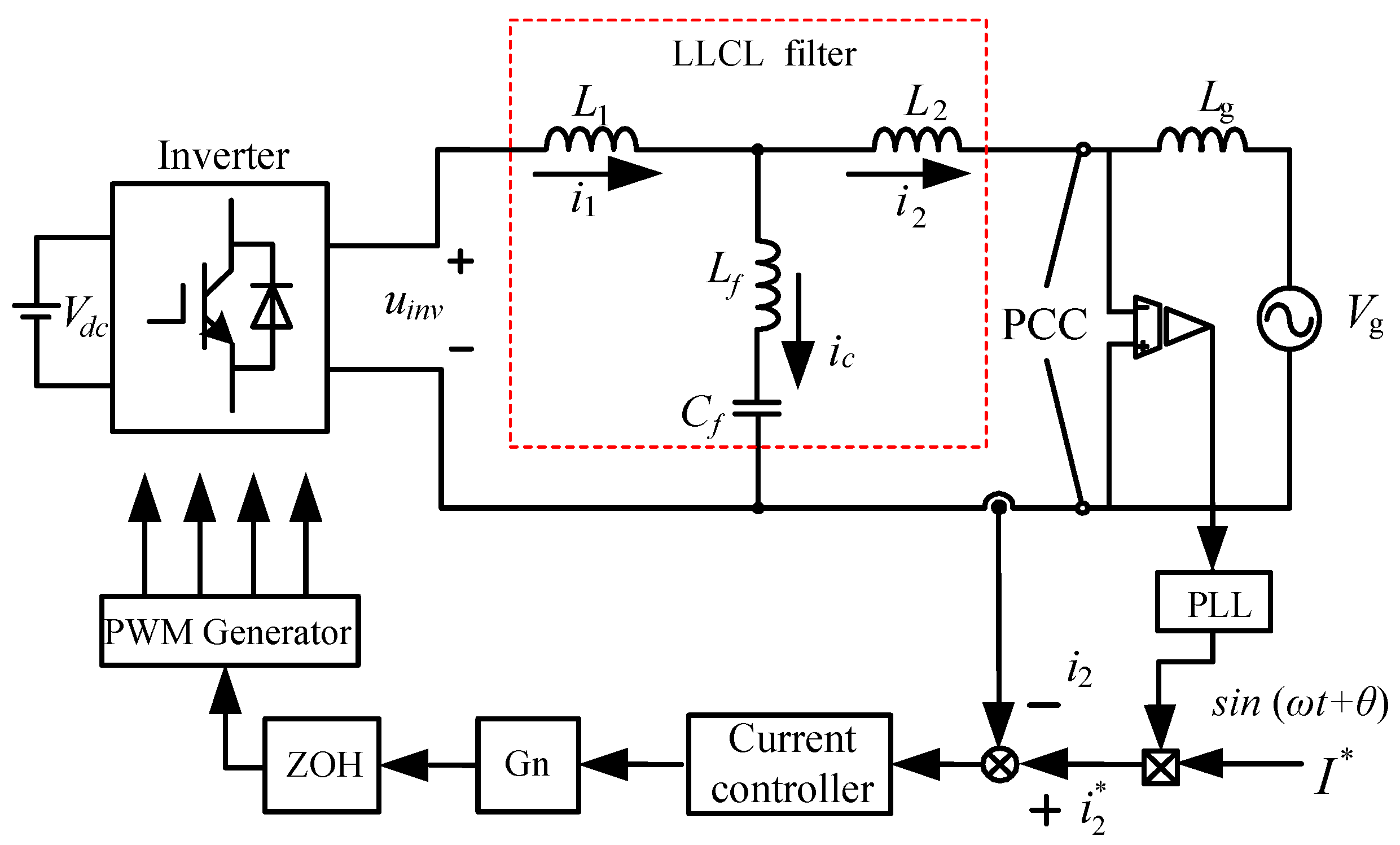
The LLCL GTI and its topology are shown in
Figure 1. Where the inductor
and capacitor
form a series resonant branch;
is the equivalent grid impedance; the inductor on the inverter side and the inductor on the grid side are
and
respectively. The control system uses a phase-locked loop to obtain the grid-tied current instruction
synchronized with the grid voltage
. In the control algorithm module, PIMR repetitive controller
is used, the transfer function of it is
where
is gain of n-order resonance controller,
;
;
is the proportional controller gain,
is the repetitive controller gain,
is fundamental period of the reference signal.
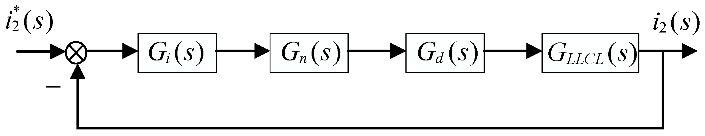
is the BF used to suppress the resonant peak of the LLCL filter. The control block diagram of the inverter system is shown in
Figure 2. Because when digital control is adopted in LLCL GTI, PWM modulation will introduce computation delay and modulation delay, which is represented by
, and it can be approximated as
where
is the sampling period,
,
is sampling frequency,
= 10 kHz. According to
Figure 1, it could be inferred that the transfer function of the LLCL filter is
The resonant frequency of the LLCL filter is
According to (3), the anti-resonant frequency of the LLCL filter is
Generally, the anti-resonant frequency is designed as the SF to suppress the switching harmonics [
7].
When
, the transfer function of the LCL filter can be obtained.
The resonant frequency is
From the transfer functions of the LCL filter and LLCL filter, their Bode diagrams are plotted in
Figure 3. Since the value of
is extraordinarily little, the resonant frequencies of the LLCL filter and LCL filter are nearly equal. They have the same harmonic attenuation capacity of −20 dB/dec in the low-frequency band. In the middle-frequency band, they are both −60 dB/dec. The LCL filter still attenuates by −60 dB/dec in the high-frequency band, while the LLCL filter drops to −20 dB/dec. However, because of the existence of the LC resonant branch, the LLCL filter generates an anti-resonant peak at the SF, which advances the harmonic suppression performance of the filter. Therefore, the harmonic suppression capability of the LLCL filter is greater than that of the LCL filter.
3. Suppression of Resonant Peak
A BF is used to suppress the resonant peak of the LLCL filter in the paper, and the expression in its complex domain is
where
and
are a resonant pole and a notch point respectively, and a constant coefficient of
is used to ensure the unit DC gain (
,
). Usually, we use Tustin transformation to discretize NF and apply it to (8).
where
, simplified (9) can be written as
where
,
and
are the parameters of the BF, and they can be expressed as
It should be pointed that, as shown in (11), the transfer function of the BF given by (10) is characterized by three parameters
,
, and
. Therefore, the BF could be easily implemented in a digital signal processor by using the Transposed Canonical Form, as it is shown in
Figure 4.
The Bode diagram of the BF is plotted in
Figure 5. It could be known that the BF generates grooves at
and resonance at
. Besides providing a phase lead of 180° in the frequency range of
, the BF also provides a phase of 0° in the range of
and
. Since
is the target resonance frequency, it should be placed in the stable region, that is,
. In order to suppress the resonant peak of the LLCL filter, it is only necessary to align the antiresonant peak
of the BF with the resonant peak
of the LLCL filter. But in fact, due to the uncertainty of power grid impedance, the
will change greatly, so it is hard to achieve
. Under this circumstances, the value of
can be appropriately reduced and need not be used to counteract the original resonant
, that is,
could be satisfied, so that the BF invariably provides a 180° phase lead for the LLCL filter under the resonant frequency.
Due to the limited control bandwidth of the PIMR repetitive controller, the controller only has a great impact on the bandwidth and does not contribute significantly to the frequency outside the bandwidth. Therefore, the PIMR repetitive controller can be regarded as a proportional gain to evaluate the stability in the high-frequency band, which could be assumed
and
c is a constant. According to (12), the loop gain of the filter with and without BF could be plotted, as shown in
Figure 6 and
Figure 7.
Figure 6 plots the Bode diagram of loop gain and the BF when the notch point of the BF is aligned with the resonant peak of the filter without considering the change of grid impedance, and
Figure 7 shows the Bode diagram of loop gain and the BF when the notch point of the BF is not aligned with the resonant peak of the LLCL filter.
Table 1 gives the parameters of a single-phase LLCL GTI.
As shown in
Figure 6, when BF is not added,
can be seen as constant.
traverses −180° at
and has an infinite resonant peak. When the BF is added, because the BF provides a 180° phase lead, the phase diagram of
no longer traverses −180° at
, and the −180° crossover is increased from the original
to
. When grid impedance is considered, the resonant frequency of the system becomes smaller, as shown in
Figure 7.
is usually set to the minimum value that
could achieve to ensure the system is robust enough. It is known from (13) that when
is infinity,
is the minimum.
Figure 8 is the system Bode diagram when
2 mH, 4 mH, and 6 mH. It can be known from the figure that their amplitude margins are 26.7 dB, 24.3 dB, and 22.9 dB at
respectively when
2 mH, 4 mH, and 6 mH. And all three of them have a phase margin of 23°, so the control system can remain stable.
According to the above analysis, we could know that the BF must satisfy the stability at and .
4. Stability Analysis of Current Controller under the BF
The grid current contains a lot of low-frequency harmonics in the GTI system, so it is essential to choose the appropriate current controller to dispose of it. Because the PIMR repetitive controller has strong harmonic suppression capacity and great dynamic performance, the PIMR repetitive controller is selected in this paper. The controller consists of a repetitive controller in parallel with a proportional gain controller, which reduces a large number of parameters of the traditional proportional multi-resonant controller, its expression in the discrete domain is
As shown in
Figure 9,
is an internal function and is constant in the paper, that is
. The main purpose of the existence of
is to increase the peak gain of the repetitive controller at a high-frequency range, to improve the stability of the system.
,
N refers to the sampling times in each period,
refers to the fundamental frequency of power grid.
is the phase advance compensator.
is a low-pass filter for attenuating high-frequency signals. As shown in (15),
is the controlled object, which refers to the product of the LLCL filter and BF in the paper, that is
The discrete repetitive control expression is
The tracking error of the system is
The characteristic polynomial is
The system will be in a stable state if the following two conditions are met.
①: All roots of are in the unit circle.
②: .
Substitute (16) into ②, We can get the following:
To be satisfied (20), it needs to be satisfied
Because the frequency of the reference signal and the interference signal is an integral multiple of the fundamental frequency, (22) could be get by substituting
into (21)
According to the frequency characteristic:
where
and
are the amplitude-frequency characteristics and phase-frequency characteristics of the
respectively.
Substitute
and
into (22), We can get the following:
The exponential function
e is expanded according to the Euler formula, (24) could be expressed as
Due to
,
, (25) necessarily requires that is
The system is stable when
and
m satisfy (26) and (27). Formula (26) contains only one parameter
m, so the value of
m could be confirmed first, and then the value of
could be confirmed by (27). The value of
could be confirmed by condition ①, and the fourth-order Butterworth filter
is selected in the paper. The cutoff frequency of it is 1 kHz, that is
According to [
26], they could be acquired as follows:
,
,
.
With increasing grid-tied power, the power grid is getting weaker and weaker, which has a great impact on the performance of GTI. Therefore, the designed control system should have strong robustness in response to the changes in grid impedance. If the impedance of the power grid changes, it could be seen from the analysis in the second section that the resonance zero point
of the BF should be designed at the minimum value that can be attained by the resonance point
of the LLCL filter, so the system is stable. According to (22), we define
If
, the end of vector
is in the unit circle, which means the system is stable [
26]. Because
is the stability criterion of the whole system, it is necessary to regard the calculation delay of
, so that
, the stability criterion becomes
Therefore,
could be used as the stability criterion of the whole system. When
2 mH, 4 mH, and 6 mH, the trajectory of
is plotted in
Figure 10, it is easy to see that the trajectories are all in the unit circle. Therefore, the proposed control scheme is robust to the variety of power grid impedance.
5. Simulation Verification
To testify to the feasibility of the theoretical analysis, the model of the LLCL inverter shown in
Figure 1 is built by MATLAB/Simulink and the simulation analysis is conducted. The simulation parameters are shown in
Table 1.
Figure 11 is the grid-tied current waveform before and after the control switch. From
Figure 11, at the beginning, it is cut to the state of the BF, the grid-tied current waveform is smooth, and the system remains stable. When the system is cut to the state without BF, the grid-tied current begins to oscillate and the system rapidly loses stability. Therefore, the proposed BF can suppress the resonance and make the system stable.
Figure 12 and
Figure 13 are the Fourier analysis of the grid-tied current of the LLCL filter and LCL filter under BF respectively. By comparing the Total Harmonic Distortion (THD) of the two figures, we could see that the filtering effect of LLCL GTI is better. And the high-frequency harmonic content of the grid-tied current of the LCL filter at the SF is 0.06%, while that of the LLCL filter is less than 0.001%. It could be known that the high-frequency harmonics at the SF are effectively filtered out by series branches of the LLCL filter, and the low-frequency harmonics are suppressed by PIMR repetitive controller.
Figure 14 plots grid voltage and current waveforms of LLCL filter with
mH. From
Figure 14, the grid-connected current waveform has no large fluctuation and distortion, and the grid voltage and the grid current is in the same phase. Therefore, the proposed control strategy can make the system have better steady-state performance.
Figure 15,
Figure 16 and
Figure 17 show the Grid-tied current waveform before and after the control switch with
2 mH, 4 mH and 6 mH. The THD of the three cases is 1.52%, 1.47%, and 1.49%, respectively. From the THD value, it can be seen that the value of THD is lower than the international standard, so the BF method can reduce the adverse impact of power grid impedance to a certain extent. At the same time, it could be known that when the BF is enabled, the waveform of the grid current is smooth, and when the BF is disabled, the current waveform rapidly oscillates and becomes unstable. This verifies that the proposed control strategy is still valid even in the weak power grids.
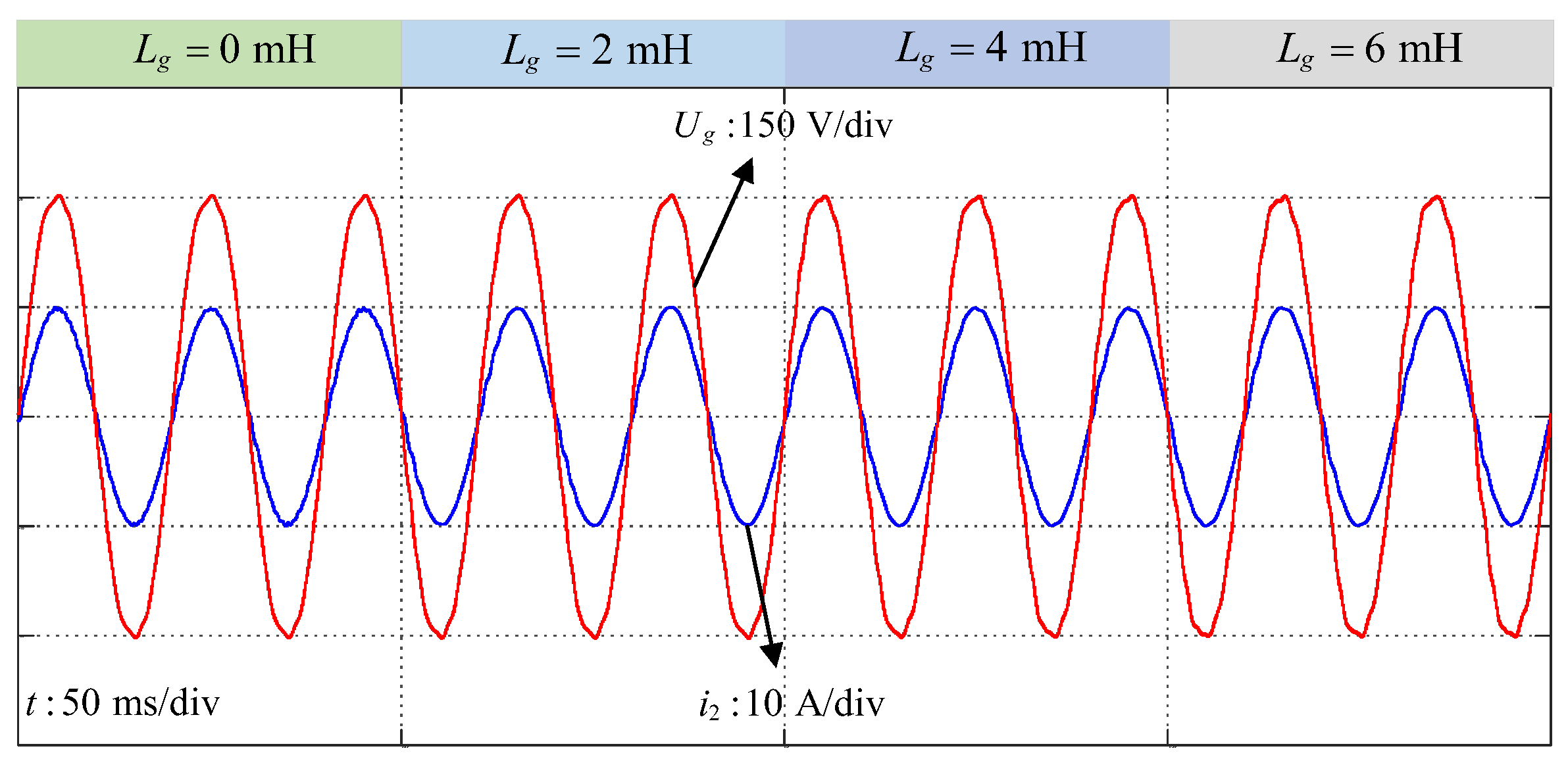
According to different grid impedances, the impedance values are switched every 50 ms to obtain the grid voltage and current waveforms as shown in
Figure 18. By switching between different
, it could be known that grid voltage and current waveforms are smooth and basically unchanged even at the moment of switching, it could be confirmed that even in the weak power grids, the system can also show excellent performance and have strong robustness.
Figure 19 shows the simulation results of power grid current under a given sudden change of current value. It is shown that when the given current suddenly changes from 5 A to 10 A, the grid-tied current can quickly track the given value and complete the mutation in only 60 ms, which is in line with our expectations, so it can be determined that the proposed control strategy has a rapid convergence speed and great dynamic performance.


