Article

Investigation on Convection Heat Transfer Augment in Spirally Corrugated Pipe

1
Institute of Building Energy and Thermal Science, Henan University of Science and Technology, Luoyang 471023, China
2
Key Laboratory of Renewable Energy, Chinese Academy of Sciences, Guangzhou 510640, China
3
Guangzhou Institute of Energy Conversion, Chinese Academy of Sciences, Guangzhou 510640, China
4
School of Information Technology and Urban Construction, Luoyang Polytechnic, Luoyang 471942, China
*
Authors to whom correspondence should be addressed.
Energies 2023, 16(3), 1063; https://doi.org/10.3390/en16031063
Submission received: 16 December 2022 / Revised: 16 January 2023 / Accepted: 17 January 2023 / Published: 18 January 2023
(This article belongs to the Topic Applied Heat Transfer)

Abstract

:
A numerical simulation on the heat transport augmentation and flow drag behavior of spirally corrugated pipes was performed. The simulation was conducted on the basis of the experimental results documented in the published literature. The influence of the thread height and pitch on the hydraulic–thermal performance as well as the mechanism of the convection heat transport development inside the spirally corrugated pipe were explored. It was discovered that the convection heat transport performance elevates in the Reynolds number region of 4000~13,000 as the thread height rises or the Reynolds number enlarges, but it declines when the thread pitch extends. The convection heat transport performance marked by the Nusselt number of the spirally corrugated pipe could reach 2.77 times that of the plain pipe, while the flow resistance coefficients of spirally corrugated pipes are 89~324% above that of the plain pipe. It enlarges with the rise in thread height but declines with the extension of the thread pitch. It also reduces when the Reynolds number enlarges. The factors of overall heat transmission performance for all the spirally corrugated pipes are above 1.00, and they increase in the Reynolds number region of 4000~7000 and then decrease in the Reynolds number region of 7000 to 13,000. The secondary flow at the cross-sections and the vortex between two adjacent corrugated grooves are the basic causes of the promotion of convection heat transport inside the spirally corrugated pipes. The secondary flow near the pipe wall both disrupts the border layer and boosts the radial interfusion of the fluid. In addition, the existence of vortexes makes the secondary flow act on the convection heat transmission continuously and positively in the region close to the pipe wall.

1. Introduction

Heat exchangers are essential energy conversion equipment in industrial fields. It is of practical significance to develop a new type of heat exchanger using a highly efficient heat transfer enhancement technique for promoting energy conservation and emission reduction and achieving carbon neutrality in China. Changing the shape of the heat exchange surface or attaching the destabilization element around the heat transmission surface is the ordinary approach to developing heat delivery elements, such as the spirally corrugated pipe [1], finned pipe [2], twisted elliptic pipe [3,4,5], and dimpled pipe [6], which all belong to this category. Spirally corrugated tubes can effectively enhance heat transport with a relatively small flow resistance [7], and they are easy to manufacture. Therefore, corrugated tubes are used extensively to enhance the heat transfer of shell and tube heat exchangers. Scholars have conducted extensive research on SCPs from the aspects of the inside flow and heat transfer characteristics [8,9,10,11,12,13,14,15], different working fluids [16,17,18,19,20,21,22], structure optimization and improvement [23,24,25], and development of novel heat exchangers [26,27,28,29,30,31].
Hærvig et al. [8] numerically elaborated upon the heat transmission characteristics in 28 SCPs and observed that a further increase in thread height would result in a small elevation in convection heat transmission but a prominently larger flow drag for the cases of high thread height. Hido et al. [9] evaluated the friction loss and enhancement in heat transfer coefficients experimentally and found the optimal tube geometry parameters. Based on experimental verification, Córcoles-Tendero et al. [10] inquired into the convective heat transmission characteristics in SCPs by means of numerical simulation and obtained relatively accurate simulation results. Qin et al. [11] applied the particle image velocimetry system to measure the instantaneous flow field inside SCPs. They found that the SCP could generate multiple longitudinal vortices to accelerate convection heat transmission inside the pipe in the absence of external heat transfer enhancement technology. Zhang et al. [12] concluded that the vortex between two adjacent corrugated grooves was the root cause of the heat delivery improvement in the corrugated pipes. Al-Obaidi and Alhamid [13,14,15] numerically investigated the thermohydraulic performance of SCPs; they examined the flow behavior, friction resistance, and heat transport performance inside SCPs with varying geometrical configurations and developed the correlations for heat transport performance calculation.
In view of the different physicochemical properties of various working fluids on the convection heat transmission performance, some researchers analyzed the convection heat transmission characteristics of different working fluids flowing through SCPs. Vicente et al. [16] experimentally researched the tube side flow behavior and convection heat transmission performance for SCPs with water and ethylene glycol as a working medium. In addition, a dimensionless parameter associated with the flow and convection heat transmission characteristics was defined, and the correlated formulas for the calculation of the flow resistance and convection heat transmission performance were obtained. Yang et al. [17] examined the frictional loss and convection heat transmission performance of four SCPs with different geometric parameters by utilizing oil and water. The results revealed that SCPs increased the convection heat transmission performance by 0.3~1.2 times in the case of increasing the friction coefficient of the flow resistance by 0.3~1.6 times in contrast to the plain pipe (PP). Rozzi et al. [18] took fluid foods as a medium to examine the convection heat transport and flow drag characteristics in SCPs. Some researchers also used the SCPs in refrigeration devices to develop efficient evaporators or condensers. It is very important to clarify the boiling and condensation heat transfer characteristics of refrigerant in the SCPs. Laohalertdecha and Wongwises [19] concluded that the thread pitch affected the convection heat transmission performance promotion and flow drag enlargement significantly through experiments with R-134a. Aroonrat and Wongwises [20] researched the thermal–hydraulic performance improvement with the usage of corrugated tubes for evaporating flow conditions. Li and Tang [21] developed a simulation model coupled with a microchannel heat exchanger model to explore the drop-in alternative mixtures for R134a regarding a mobile air conditioner. Li and Hrnjak [22] presented the phase separation characteristics in the vertical second header of a condenser through a computational fluid dynamics simulation. The results showed that the liquid separation efficiency decreased as the vapor separation efficiency increased, following a linear trend in the experimental range.
The application of SCPs can be considered as an efficiently passive enhancement method to upgrade heat exchangers, and heat exchangers composed of SCPs have been continuously improved since their development. A double tube heat exchanger made up of SCPs, instead of PPs, could improve the convection heat transmission performance by about 1.73 times [23]. Qian et al. [24] improved the convection heat transmission performance of SCPs by increasing the number of threads and assessed the optimization results with the performance evaluation of comprehensive convection heat transfer. Yang et al. [25] identified the influencing factors including the head number and ripple depth and space on convection heat transmission performance using the Taguchi method and obtained the optimal structure to upgrade heat transmission performance. With the gradual revelation of the heat transmission intensification mechanism and the continuous optimization of the geometric structure of SCPs, the heat exchange equipment applying SCPs as the core heat transfer units are emerging in an endless stream. Liu et al. [26] proposed a longitudinal flow baffle rod heat exchanger using SCPs with different spiral heads and researched the shell-side thermohydraulic performance. The results implied that the overall heat transmission performance of SCPs with single heads is the best. With the external expansion of SCPs, Wang et al. [27] proposed a SCP tube and shell heat exchanger and analyzed the influence of the pipe bundle arrangement on the thermohydraulic characteristics of the heat exchanger. Wu et al. [28] and Moya-Rico et al. [29] examined the heat exchange performance of a concentric pipe heat exchanger composed of SCPs and explored the effect of the physical parameters of SCPs on the heat exchanger performance. Hu et al. [30] used three corrugated pipes to improve the intermediate heat exchanger performance and investigated its thermohydraulic characteristics. Pethkool et al. [31] inquired into the convection heat delivery improvement in a concentric pipe heat exchanger made up of SCPs with water at a turbulent state.
Scholars have carried out abundant research on the fluid flow and convection heat transmission performance in SCPs in terms of structural optimization and application. Many studies reported that the heat transfer performance of SCPs was better than that of PTs. Is there any basic reason to reveal this phenomenon? How to optimize the tube type of SCPs? Is there a better design scheme for the heat exchangers developed with SCPs? The premise to answer these questions is to clarify the mechanism of the heat transfer enhancement of SCPs. However, past studies have reported on the heat transfer enhancement effect more than the analysis of the heat transfer enhancement mechanism. Clarification on the heat transfer enhancement mechanism of SCPs is the basis for realizing effective heat transfer enhancement and optimizing the tube shape. Meanwhile, the geometric shape of the SCP is inseparable from its heat transfer augmentation effect. In our opinion, the geometric structure is an external factor, which induces the spiral flow inside the pipe, then the spiral flow acts on the boundary layer to reduce the thickness of the boundary laminar flow. Therefore, the relationship between the geometric structure size and the spiral flow and the improvement mechanism of convection heat transmission in SCPs needs to be explained in depth.
Based on the existing experimental data validation, the paper examines the convection heat transport and flow drag performance of SCPs through numerical calculations. The variations of the convection heat transmission and flow drag performance of SCPs with their geometric parameters and the flow parameter are explored. In addition to the external factor of heat transfer enhancement, the root causes of convection heat transfer improvement in SCPs are provided. Then, the elevation of the convection heat transmission performance of SCPs is evaluated based on the comprehensive heat transmission performance.

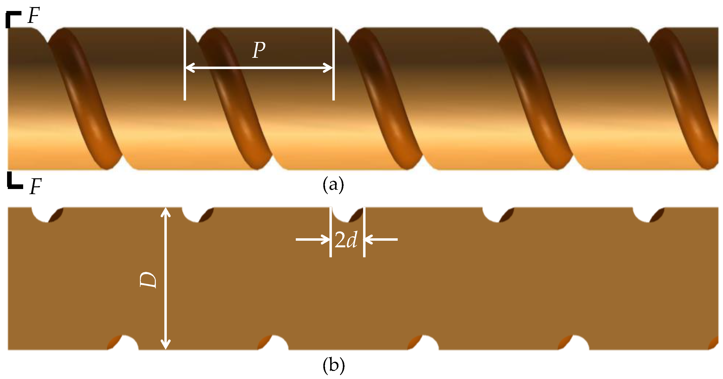
2. Geometrical Models

The SCP is usually made from a PP with equivalent diameter using cold roll-forming technique. In addition, the sectional shape of the groove which is produced by the technique on the tube surface is not a regular semicircular shape. For convenience of setting up SCP geometrical models, the sectional shape of the groove was simplified as approximately a semicircle, and the wall thickness was ignored. The simplified geometric model is shown in Figure 1. The inner diameter of the SCP is D, and the height of thread is d. The pitch of thread is P, and it is described as the distance in axis direction through which a ridge or crest turns 360 degrees along the pipe. The normalization forms for the geometry characteristics are thread pitch ratio (p/De) and thread height ratio (d/De) in this paper. For ease of comparative analysis on the influences of geometry dimensions on improvement of convection heat transmission and enlargement of flow drag in the pipe, the SCP models with six geometric structures were determined using Taguchi method with reference to the structural dimensions of the SCP in the actual manufacture process. The parameters of the physical models are presented in Table 1. The pipe 6# as the reference case is a PP, and it has the same internal diameter as the SCP.

3. Methodology

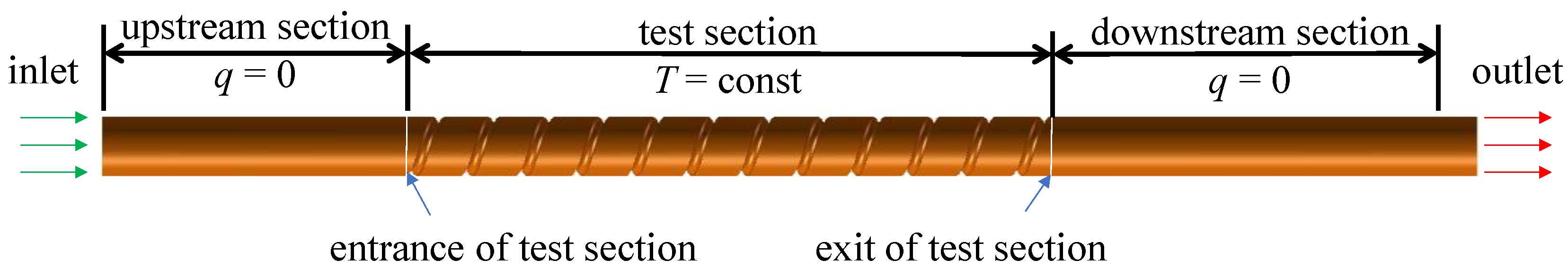
3.1. The Boundary Condition

As displayed in Figure 2, apart from the test section, each pipe attaches to the upstream and downstream sections to ensure that fluid fully develops in the calculation domain and remove the influence of reflux which may occur at outlet. Each of the test section lengths for the six pipes is 1.00 m. Adiabatic boundary condition is imposed on the walls at the upstream and downstream sections. The test section is non-slip wall, and the wall temperature is specified as 353 K. Accordingly, radiation heat transfer is neglected as the wall temperature is not very high. A uniform velocity is determined at the inlet, where the fluid temperature is 300 K. The gauge pressure at outlet is 0. The fluid used in the simulation is water, and the physical property is listed in Table 2.

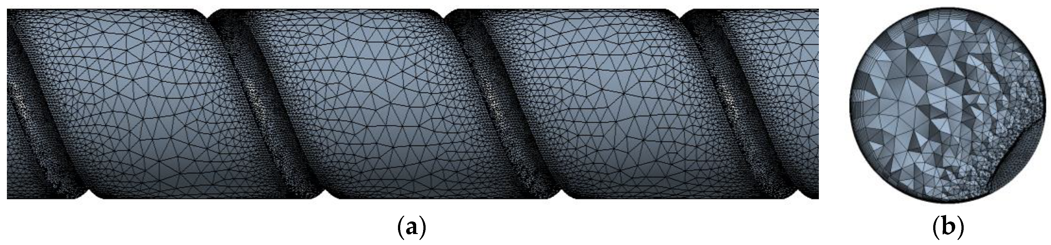
3.2. Grid Independence Verification

To discretize the calculation domain, polyhedral grid distribution was considered for the fluid region. Taking account of the effect of continuously corrugated grooves on thermohydraulic performance inside the pipe, it was necessary to set up relatively dense grids near the spirally corrugated groove wall to calculate the distribution of velocity and temperature accurately. Nevertheless, excessively dense grids would result in a decrease in calculation efficiency. Therefore, it was essential to conduct grid independence verification with the aim of calculating the flow distribution and temperature field in the vicinity of corrugated grooves accurately and improving the calculation efficiency simultaneously.
For pipe 4#, when the Reynolds number (Re) was 8500, rough, fine and refined grids were used for numerical calculation, respectively. The calculation results are listed in Table 3. When the grid distribution turns from a rough to a fine type, the Nusselt number (Nu) and factor of flow drag (f) increase by 10.61 and 17.10%, respectively, with increasing the number of grids. However, the Nu and f remain almost unchanged as the grid setting turns from fine type to refined type. It can be concluded that the growth in the number of grids has no influence on the numerical results when the number of fine grids increases to the number of refined grids, which shows that the grid configuration of fine type can confirm the precision of numerical calculation. All the numerical calculations in this paper adopt the fine grid configuration method; that is, the first layer height (Δh) of the grids for spirally corrugated groove walls meets the dimensionless quantity y+ ≈ 1 [32]. In addition, the subsequent grid height increases gradually with a growth rate of 1.2 times until the grid size is consistent with that in the mainstream zone. The grid distribution for pipe 4#, when the Re is 8500, is shown in Figure 3.

3.3. Numerical Procedure

Since the flow was assumed as fully developed, the term of time was ignored. The equations including mass, momentum, and the energy of water in SCPs shown below are discretized using finite volume method. They were resolved with simple algorithm and implicit scheme. QUICK discrete scheme was used for the convection term. The momentum equation adopted second-order upstream discrete scheme. Convergence residuals for velocity and energy were set to 10−5. The above operations and settings are realized through Fluent 18.0.
U = 0
ρ U U = p + μ 2 U
ρ c p ( U T ) = λ 2 T
Symbol description: U, velocity, m s−1; ρ, density, kg m−3; p, flow resistance Pa; μ, viscosity kg m−1 s−1; cp, specific heat of working fluid at constant pressure, J kg−1 K−1; T, temperature, K; and λ, thermal conductivity, W m−1 K−1.
The equations for the SST kω turbulent model are as follows:
X i ( ρ k u i ) = X j ( Γ k k X j ) + G k ˜ Y k + S k
X i ( ρ ω k u i ) = X j ( Γ ω ω X j ) + G ω Y ω + D ω + S ω
where Gk is the turbulent kinetic energy due to the average velocity gradients and Gω is the indicator of ω.
G k ˜ = min ( G k ,   10 β k ω )
G k = ρ u i u j ¯ ( u j X i )
G ω = α υ t G k
α = α α 0 + R e t / R ω 1 + R e t / R ω
where vt is the turbulent kinematic viscosity, β* is a constant of the model, Rω is equal to 2.95, and α is calculated as follows:
α = F 1 α ,   1 + ( 1 F 1 ) α ,   2
α ,   1 = β i ,   1 β k 2 σ ω ,   1 β
α ,   1 = β i ,   2 β k 2 σ ω ,   2 β
where k = 0.41, βi = 0.072, and α = α = 1.0.
Γk and Γω are the effective diffusions of k and ω, which are defined as:
Γ k = μ + μ t σ k
Γ ω = μ + μ t σ ω
where σω and σk represent turbulent Prandtl numbers for k and ω:
σ k = 1 F 1 / σ k ,   1 + ( 1 F 1 ) / σ k ,   2
σ ω = 1 F 1 / σ ω ,   1 + ( 1 F 1 ) / σ ω ,   2
where μt is the turbulent viscosity, which is calculated by:
μ t = α ρ k ω
α* is the damper of turbulent viscosity and is defined by:
α = α α 0 + R e t / R k 1 + R e t / R k
R e t = k ρ ω μ
where Rk = 6, α* = βi/3 = 0.024. F1 is calculated by:
F 1 = tan ( ϕ 1 4 )
ϕ 1 = min [ max ( k 0.09 ω y ,   500 μ ρ ω y 2 ) ,   4 ρ k σ ω ,   2 D ω + y 2 ]
D ω + = max [ 2 ρ 1 σ ω ,   2 1 ω k X j ω X j ,   10 10 ]
D ω + is the positive portion of the cross-diffusion term. Yk and Yω are the indicators of dissipation for k and ω, which are defined as:
Y k = ρ β k ω
Y ω = ρ β ω 2
β i = F 1 β i ,   1 + ( 1 F 1 ) β i ,   2
D ω = 2 ( 1 F 1 ) ρ σ ω ,   2 1 ω k X j ω X j
Dω is the penetrating term (relative to D ω + ) in cross section. Sk and Sω are the possible conditions of the source.

3.4. Data Interpretation

The characteristic length was determined as follows:
D e = 4 A / C
Symbol description: De, equivalent internal diameter, m; A, sectional area of the pipe, m2; and C, wetted circumference, m. The length of A and C can be collected using 3D drawing software for each physical model.
The Re of water in the test section was defined by:
R e = ρ U m D e / μ
Symbol description: Re, Reynolds number; Um, average velocity of the fluid, m s−1.
The average temperature of water in the test section could be obtained using integration operation from the following formula:
T m = U x T ( x , y , z ) d z d y / U x d z d y
Symbol description: Tm, average temperature of the fluid, K; Ux, velocity in x direction, m s−1; and T(x, y, z), fluid temperature at a coordinate point, K.
The convection heat transmission coefficient of the test section was determined using:
h = F t q / ( T w T m ) d F t / F t d F t
Symbol description: h, coefficient of convection heat transmission, W m−2 K−1; q, heat flux, W m−2; Tw, pipe wall temperature, K; and Ft, total heat transfer area of the pipe, m−2.
The mean value of Nu at test section was obtained:
N u = h D e / λ
Symbol description: Nu, Nusselt number.
Prandtl number was defined as:
P r = c p μ / λ
Symbol description: Pr, Prandtl number.
The flow resistance of the test section was obtained using:
Δ p = p in p out
Symbol description: Δp, pressure difference, Pa; pin, pressure at the entrance of test section, Pa; and pout, pressure at the exit of test section, Pa.
The flow drag coefficient of the test section was obtained from the following equation:
Δ p = f L t D e ρ U m 2 2
Symbol description: f, friction coefficient; Lt, test section length, m.
The convection heat transmission elevation performance of the SCPs was evaluated by comparison with the numerical calculation results against the reference case of a PP with equal inner diameter.
The heat exchange tube can be regarded as an open thermal system that does not perform work. The reason why the convective heat exchange process can continue is due to two reasons: one is the temperature difference between the fluid inside and outside the tube, and the other is the upstream fluid is transported into and out of the tube under the drive of power. Expanding the heat transfer surface (such as adding fins or ribs) or modifying the wall surface of the heat exchange tube (such as forming a spiral groove on the tube wall) can increase the heat transfer capacity under the same temperature difference, while expanding the heat transfer surface or modifying the wall surface will inevitably increase the power for fluid delivery. It is a reasonable point of view to evaluate heat transfer enhancement under the same transmission as power consumption. The overall convection heat transfer performance factor, in this respect, was defined as [33]:
η = N u / N u ref ( f / f ref ) 1 / 3
Symbol description: η, overall heat transmission performance factor; Nuref, Nusselt number of the reference pipe; and fref, friction coefficient of the reference pipe.
For the heat transfer enhancement tube developed based on the plain tube, the plain tube is usually taken as a reference object, and the improvement effect of heat transfer capacity is analyzed under the condition that the heat transfer enhancement tube consumes the same transport work as the plain tube. If the value of η is greater than 1, it means that the heat transfer enhancement effect is obviously greater than the increase in flow resistance after adopting strengthening measures, and it is considered that such strengthening measures are worth recommending. If the value of η is equal to 1, it means that the effect of heat transfer enhancement is offset by the increase in flow resistance, but the realization of heat transfer enhancement measures often requires a cost. Generally, the strengthening measures are not recommended. If the value of η is less than 1, it means that the heat transfer enhancement effect is not significant, which is unacceptable.

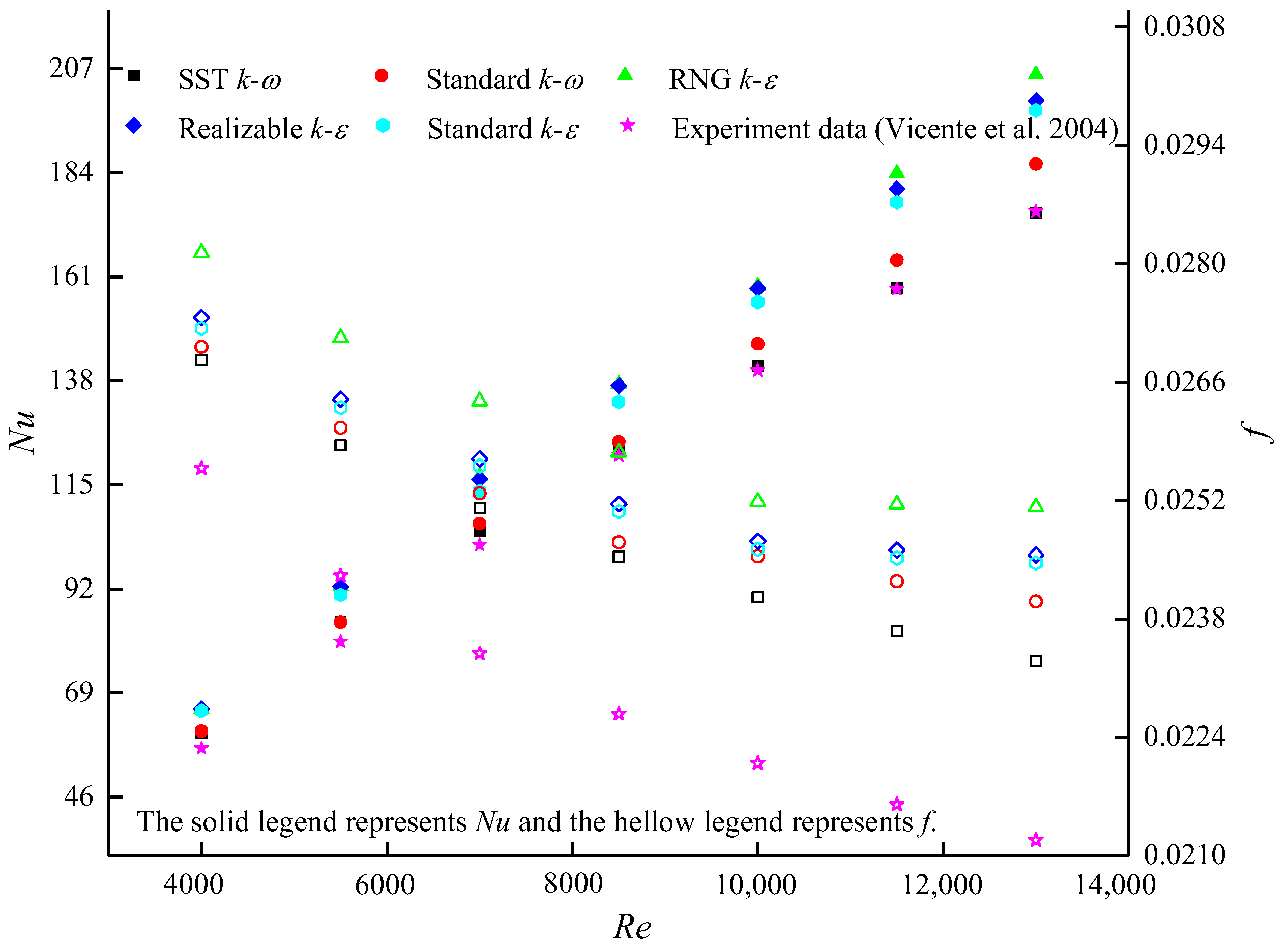
3.5. Model Validation

According to the different turbulence processing scales in the Navier–Stokes equation, numerical simulations are mainly divided into three methods: the direct numerical simulation (DNS), the Reynolds averaged Navier–Stokes (RANS), and the large eddy simulation (LES). The DNS can obtain accurate information of turbulence field, which is an effective means to study turbulence mechanism, but the common computing resources are usually difficult to meet the requirement of high Reynolds number flow simulation, so this paper does not adopt the DNS. The LES filters small-scale vortexes to calculate the motion of large-scale vortexes directly. The distribution of grids filtered is significantly related to the calculation quality, which leads to the extremely dense grid nodes of the small-scale vortexes model, requiring huge computing power. However, the RANS method can calculate the complex flow with high Reynolds number, which requires less computing power, and the calculation results obtained can meet the engineering application. The k-ω and k-ε turbulence models and their revised models are commonly used in RANS.
Apart from the grid distribution discussed above, the turbulence models are also crucial to the numerical calculation results. Although several turbulence models are frequently found in the numerical research on hydraulic–thermal characteristics inside pipes, the appropriate model should be screened using model validation for the SCP by means of comparison between computing data and existing experiment results documented in Ref. [16]. The SST k-ω, standard k-ω, realizable k-ε, standard k-ε, and RNG k-ε models were utilized to perform the model validation. In contrast to the experimental data (displayed in Figure 4), the computing data obtained with SST k-ω model appeared to have the highest accuracy (below 6.1 and 10.0% for Nu and f) for the SCP. The mean deviation between the simulation and the test results were 2.4 and 7.9% for Nu and f. The SST k-w turbulent model was also used by Li et al. [4,5] to investigate the heat transport and frictional hydraulic resistance properties inside special-shaped tubes. Therefore, the congruent simulation results indicated that the calculation method in this paper could predict hydraulic–thermal characteristics inside the SCP reliably.

4. Numerical Calculation Results and Discussion

From the numerical predictions for all geometry models, one could judge that the performance of the convection heat transmission of the SCPs preceded that of the PPs, and the flow drag of the SCPs was significantly larger than that of the PPs. Actually, the only difference between the two pipe types was whether there was a spirally semicircular groove on the pipe wall. To figure out this point, in the following text, we analyze and clarify the association of thread height and pitch to the behavior of flow drag and the promotion of heat transmission.

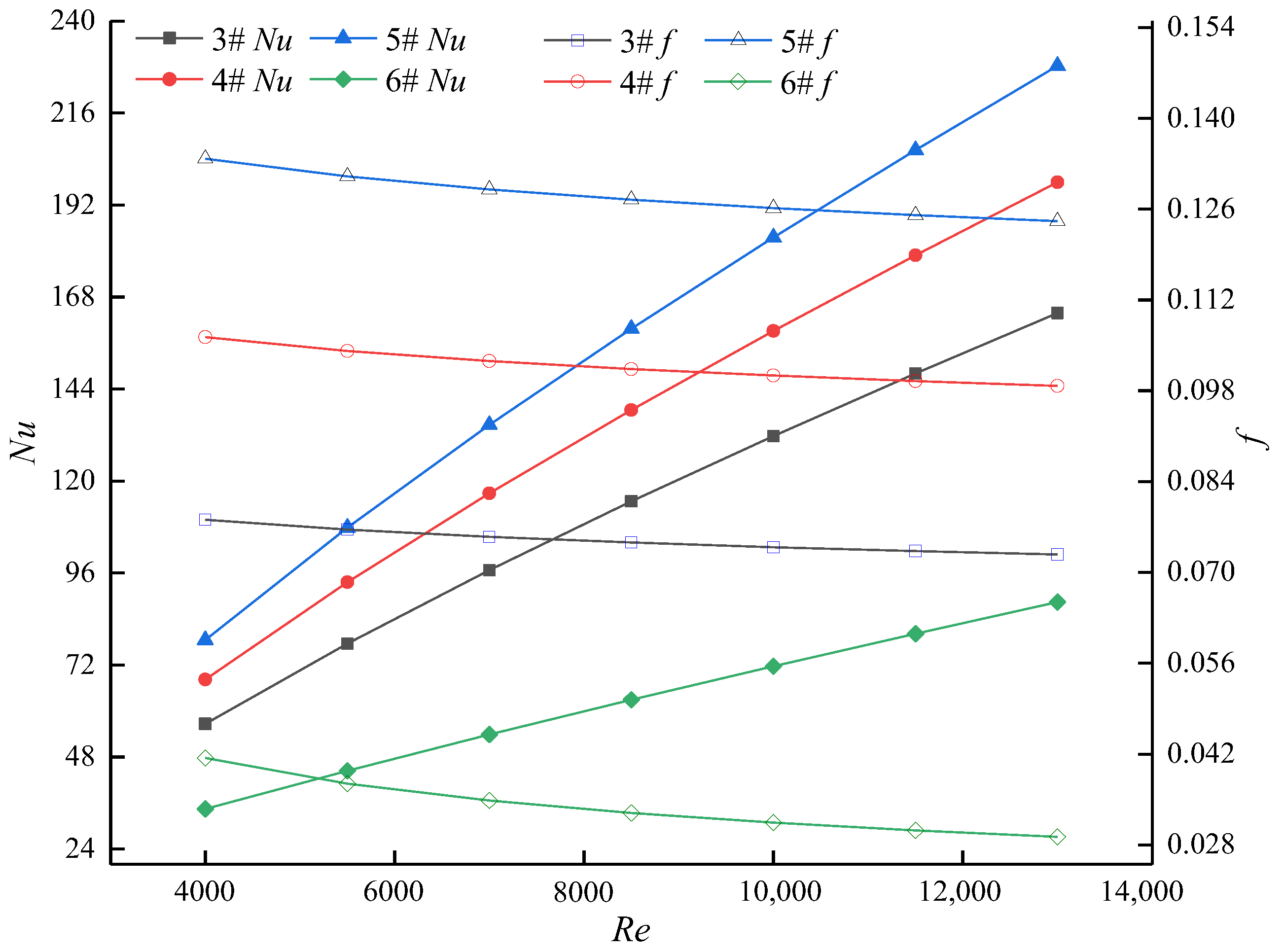
4.1. Effect of Thread Height

When the pitch of thread is specified, the variations in flow drag and the convection heat transmission performance of SCPs with different thread heights are plotted as f versus Re and Nu against Re in Figure 5. The conclusion can be drawn that both f and Nu of the SCPs outnumber those of the PPs. Figure 5 also shows that both the flow drag coefficient and Nu rise with the rise in thread height. The reason is that increasing the thread height leads to the intense disturbance of thread to the flow boundary layer and thermal boundary layer. However, the increase in thread height forces fluid in the pipe to occur periodically with sudden-expansion and sudden-contraction flow, which causes the boundary layer flow to take off the vortex and even to appear reflux, resulting in the loss of the power consumption of the flow. Eventually, the flow resistance enlarges to a large extent. In contrast to the PPs, the flow resistance coefficients of SCPs are 89~324% higher than those of the PPs, and the Nus of SCPs are 1.64~2.58 times those of the PPs when the thread height ratio increases from 0.111 to 0.218 in the Re range of 4000~13,000.
In the respect of a complementary interpretation of the variation of flow drag behavior and heat transmission enhancement, it is noticed that the effect of thread height on the secondary velocity ( U z 2 + U y 2 ) could reveal the reason for heat transmission enhancement and flow drag enlargement. As shown in Figure 6, secondary velocity distributions are evidently present at the cross sections for all the SCPs, which could be explained by the change in velocity owing to the centrifugal force induced by the continuously spiral groove. A deep groove produces heavy centrifugal force, and the secondary velocity becomes intense accordingly. The secondary velocity intensity of pipe 5# is evidently larger than that of pipe 4# and pipe 3#, and pipe 5# shows the largest Nu. Figure 6 also depicts that the secondary velocity adjoining the pipe wall outnumbers that of other regions, and the secondary flow adjacent to the wall damages the border layer and promotes the convection heat transport process. Therefore, the enhancement of convection heat transmission should be attributed to the action of the secondary flow naturally.
The secondary flow is strengthened as the thread height rises, and the fluid mixing in a radial direction will also be promoted under the positive action of the secondary flow, which inevitably causes the fluid to become more and more turbulent. However, the energy originally used to maintain the fluid flow will be dissipated in the disordered turbulence, especially in the disturbance of increasing thread height, which will eventually manifest an obvious rise in flow resistance. Consequently, the flow resistance coefficient enlarges as the thread height rises, which is depicted in Figure 5.

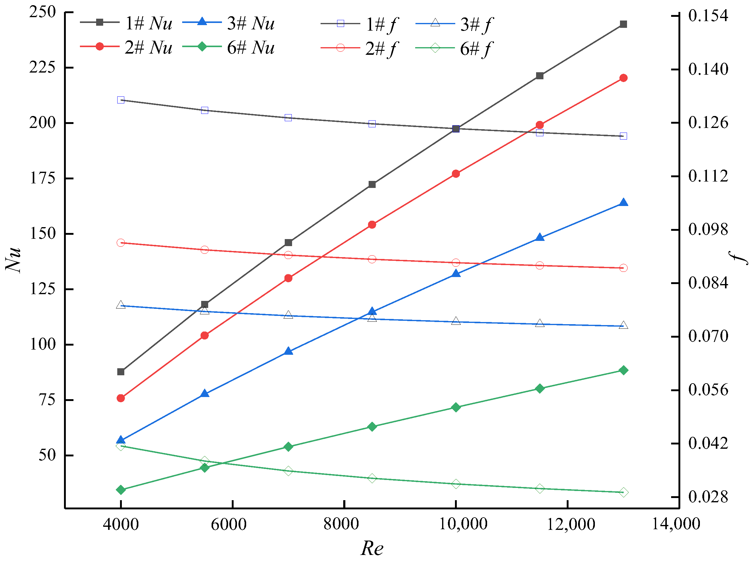
4.2. Effect of Thread Pitch

The variations in the flow resistance and convection heat transmission performance of SCPs with different thread pitches are plotted as f corresponding to Re and Nu versus Re in Figure 7. In general, the heat transmission performance becomes excellent when the thread pitch gets small. However, the flow drag increases with the reduction in the thread pitch. The main reason is the reduction in thread pitch will increase the disturbance frequency of the flow caused by the thread groove. According to the theory of boundary layers, the promotion of convection heat transfer must occur as the boundary layer is destructed frequently. However, the improvement in the convective heat transmission usually comes at the cost of power consumption. Therefore, the flow resistance coefficients of SCPs elevate with the decrease in thread pitch. Compared with PPs, the flow resistance coefficients of SCPs are 1.89~4.19 times those of the PPs, and Nus of SCPs are 1.64~2.77 times those of the PPs, respectively, when the thread pitch ratio is reduced from 0.556 to 1.633 within the Re range of 4000~13,000.
The analysis on the effect of thread height on the heat transport augmentation in Section 3.1 indicates that it is beneficial to analyze the influence of thread pitch on flow resistance characteristics and heat delivery performance with a small thread height. Then, flow patterns for pipe 1#, pipe 2#, and pipe 3# are simulated, in detail, to expound the association between thread pitch and hydraulic–thermal performance inside the SCP. The Streamtraces (white-colored lines) and velocity contours of SCPs are presented in Figure 8, from which it is observed that vortexes exist in the region between two neighboring corrugation grooves, except for pipe 3# with the largest thread pitch. The vortexes dissipate energy but destroy the border layer and intensify the turbulent mixing of the water adjoining the pipe wall, which results in the promotion of convection heat transmission.
The vortexes almost dominate all the region between two adjacent corrugated grooves for pipe 1# with the shortest thread pitch, while the vortex is close to the upstream corrugated groove and far from the downstream corrugated groove for 2#. The disturbance of the corrugated groove will promote the separation of the boundary layer and the formation of downstream vortexes. As a large pitch is specified, there will be such a section of area between two adjacent corrugated grooves. In this section, the disturbance of the former corrugated groove to the boundary layer is weakened, but the disturbance of the latter corrugated groove to the boundary layer has not formed, and the section of area extends with the increasing thread pitch. Most notably, a proper thread height and an appropriate thread pitch are vital for efficient convection heat transmission improvement; otherwise, the situation, such as in pipe 3# (with the maximum thread pitch and the minimum thread height), where no vortexes are examined, will occur. In other words, the SCP with a small thread pitch and large thread height should be used as much as possible when flow resistance allows.

4.3. Effect of Flow Parameter

From Figure 5 and Figure 7, the flow resistance coefficients of all the SCPs decline with the rise in Re, while the Nus of all the SCPs rise with the escalation of Re. With the rise in Re, the convection heat transport and momentum exchange of water become strengthened. Simultaneously, the disturbance intensity and frequency caused by the thread on the water flow are relatively enhanced. Therefore, the convection heat delivery in the pipe is strengthened. The reason why flow resistance coefficients drop gradually and tend to be gentle with the rise in Re is that flow resistance depends on the disturbance of the thread on the viscous sublayer and the turbulence in the mainstream when the Re is low, while the fluid enters a self-modeling state, where the flow develops fully, and the flow resistance is mainly determined by the pulse movement of water as the Re increases.

4.4. Comprehensive Performance Evaluation

Through the above analysis, it could be observed that the elevation in thread height and the reduction in thread pitch were conducive to the convection heat transport improvement in the SCP. However, they also caused the increase in flow resistance. Therefore, an evaluation of the comprehensive influence of the geometrical parameters on heat transmission enhancement was required.
When the overall convection heat transmission performance factor (η) is larger than 1.00, it implies the overall heat transmission performance of the SCPs outperforms that of PPs. Otherwise, the overall heat transmission performance of SCPs is worse than that of PPs. The comparison of the overall heat transmission performance between the SCP and the PP is illustrated in Figure 9.
It is evident that all the factors of the overall convection heat transmission performance are above 1.00, which reveals that the overall heat transmission performance of SCPs surpasses that of PPs. Substituting PPs with SCPs to strengthen the convection heat transport in the pipe is worthy of promotion. Figure 9 also illustrates that the overall heat transfer performance factors of SCPs increase at first and then decrease when the Re is in the range of 4000~13,000. The Re corresponding to the inflection point is about 7000. The SCP (pipe 1#) with the minimum thread pitch shows the best overall heat transfer performance, which is about 1.92~1.97 times that of PP. It can be summarized that the geometry parameters are competitive for the heat transmission intensification in the low Re region (4000~7000) for the SCPs investigated in this paper.

5. Conclusions

The convection heat transmission characteristics and flow drag behavior of SCPs with various geometry parameters were examined using numerical simulations through a finite volume method. Based on grid independence testing and model validation, the influences of thread height, thread pitch, and flow state parameters on the hydraulic-thermal performance were examined, and the augmentation mechanism of the convection heat transmission inside the SCP was explored for the fully developed flow, with Re ranging from 4000 to 13,000. Several conclusions were drawn as follows:
(1)
It was ascertained that the Nu increased with the boost of thread height and rose with the accretion of Re but decreased with the extension of the thread pitch. The Nu of the SCP could be up to 2.77 times that of the PP.
(2)
The coefficient of flow drag enlarged with the rise in thread height, but it declined with the extension of the thread pitch and the elevation in Re. The flow resistance coefficients of SCPs were 89~324% higher than that of PPs.
(3)
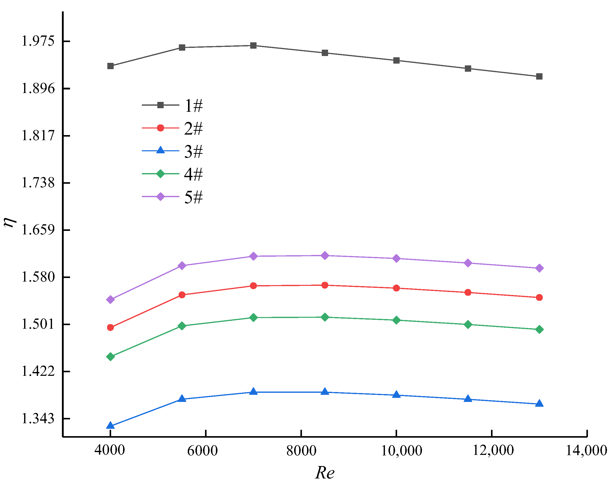
The peak factor region of overall heat transmission performance was 1.92~1.97, which was acquired for SCP 1#. The overall heat transmission performance factors for all the SCPs rose with the Re in the region of 4000~7000 and then decreased when the Re was in the range of 7000~13,000.
(4)
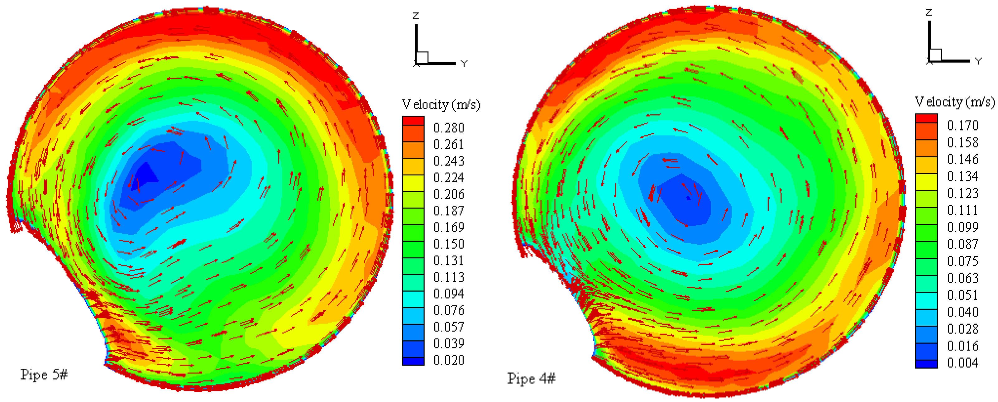
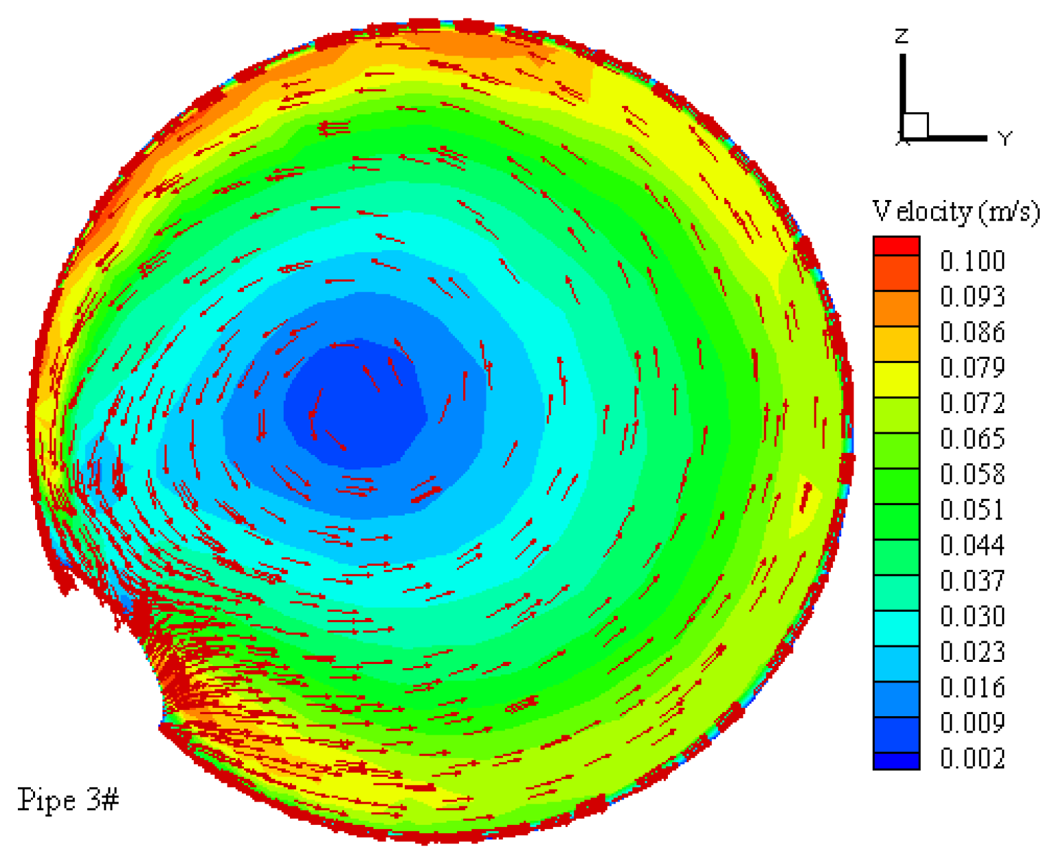
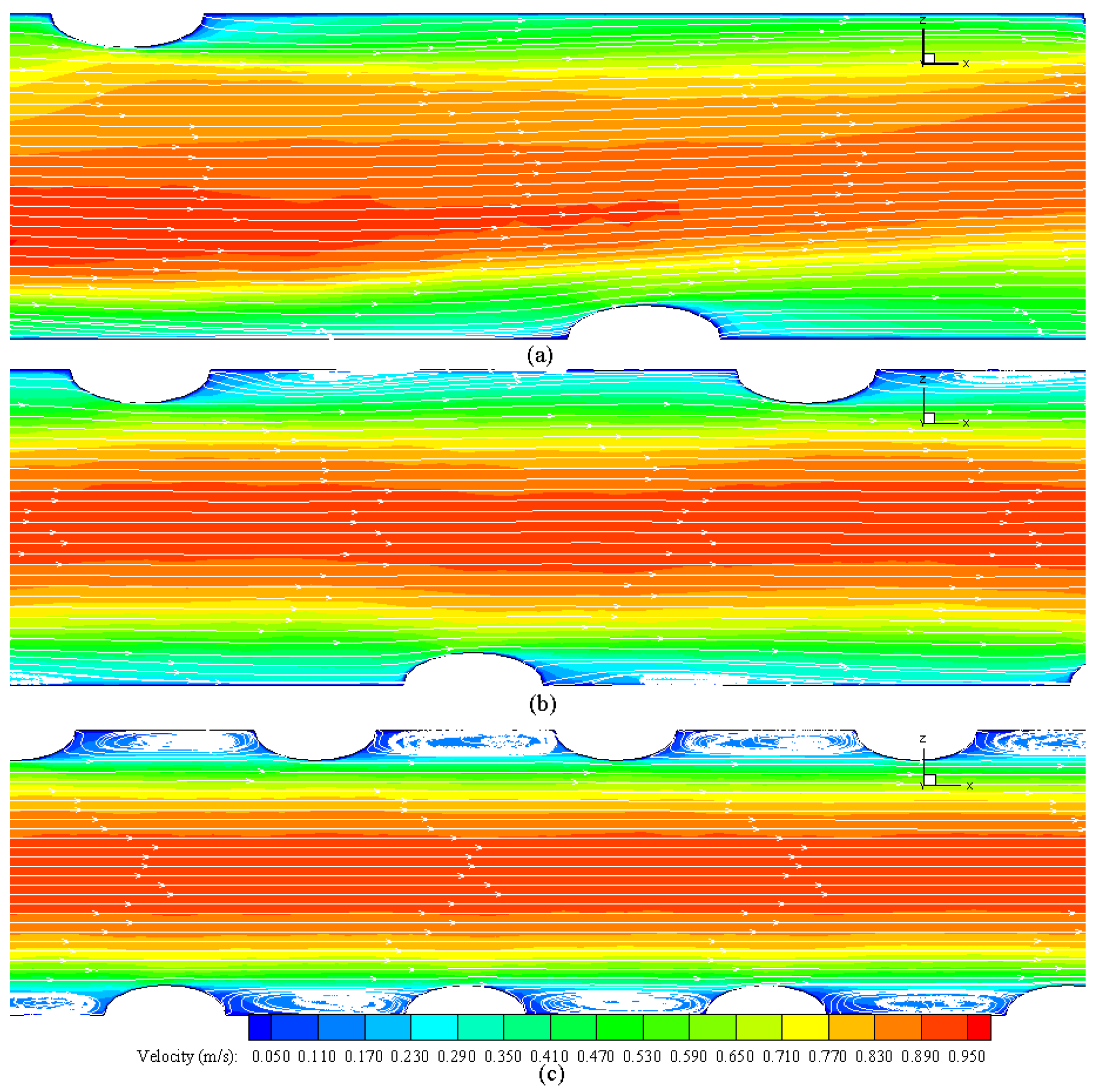
Secondary flow at the cross sections and the vortex between two adjacent corrugated grooves were the basic reasons for the promotion of convection heat transmission inside the SCPs. The contribution of secondary flow to heat transport intensification could be described as the secondary flow near the pipe wall both disrupting the border layer and making a boost in fluid mixing in a radial direction. In addition, the existence of vortexes made the secondary flow act on the convective heat transport continuously and positively in the region adjoining the pipe wall.
Considering the real situation that the temperature of the fluid in the heat exchange tube does not change much, it is generally acceptable to assume that the physical properties of the fluid in the tube are stable. However, the physical properties of the fluid will change with the change in temperature during the actual heat exchange process. Therefore, the deterministic properties’ assumption usually leads to the inaccuracy of the simulated data. In the next step, we will establish the function of fluid physical properties and temperature and build the function into the simulation process to further improve the accuracy of the simulation.
In this paper, we focus on the influence of thread pitch and thread height on heat transfer and flow performance under the condition that the inner diameters of the pipes are constant. Next, we will analyze the effects of pipe diameter, thread pitch, thread height, and flow parameters on heat transfer and flow performance in detail. Attempts to analyze the interaction of these factors on heat transfer and flow performance are also part of the work to be undertaken.

Author Contributions

Conceptualization, writing—original draft preparation, X.L.; formal analysis, writing—review and editing, S.L.; investigation, X.M.; investigation, data curation, Z.S.; data curation, visualization, G.T.; data curation, Y.X.; methodology, D.Z. All authors have read and agreed to the published version of the manuscript.

Funding

This research was funded by the Key R&D and Promotion Project of Henan Province (222102320258, 212102310327, 222102320357); Innovative Research Team (in Science and Technology) in University of Henan Province (22IRTSTHN006); Key Laboratory of Renewable Energy, Chinese Academy of Sciences (E029kf0401); Key Research Project of Higher Institutions in Henan Province (21A470002); Grant. YLU-DNL Fund 2021004; Science & Technology Innovation Talents in Universities of Henan Province (22HASTIT025); and Doctoral Research Startup Fund of Henan University of Science and Technology.

Data Availability Statement

The relevant simulation data are provided by the Institute of Building Energy and Thermal Science, Henan University of Science and Technology, and the data presented in this study are available on request from the corresponding author.

Acknowledgments

We sincerely acknowledge the Institute of Building Energy and Thermal Science, Henan University of Science and Technology and Key Laboratory of Renewable Energy, Chinese Academy of Sciences.

Conflicts of Interest

The authors declare no conflict of interest.

Nomenclature

Asectional area (m2)
Cwetted circumference (m)
Dinternal diameter (m)
dthread height (m)
Fheat transfer area (m2); section direction
ffriction coefficient
hcoefficient of convection heat transmission (W/(m2⋅K)); grid height (m)
Llength (m)
NuNusselt number
Pthread pitch (m)
PrPrandtl number
pflow resistance (Pa)
qheat flux (W/m2)
ReReynolds number
Ttemperature (K)
Uvelocity (m/s)
Greek letters
ρdensity (kg/m3)
λconductivity (W/(m⋅K))
μviscosity kg/(m⋅s)
ηoverall heat transmission performance factor
Δdifference
Subscripts
eequivalent
inflow-in; inlet or entrance
maverage
outflow-out; outlet or exit
refreference
ttotal; test section
wwall
x, y, zcoordinate direction
Special symbol
infinity
Abbreviation
SCPspirally corrugated pipe
PPplain pipe

References

  1. Kareem, Z.S.; Mohd Jaafar, M.N.; Lazim, T.M.; Abdullah, S.; Abdulwahid, A.F. Passive heat transfer enhancement review in corrugation. Exp. Therm. Fluid Sci. 2015, 68, 22–38. [Google Scholar] [CrossRef]
  2. Sadeghianjahromi, A.; Wang, C.-C. Heat transfer enhancement in fin-and-tube heat exchangers—A review on different mechanisms. Renew. Sustain. Energy Rev. 2021, 137, 110470. [Google Scholar] [CrossRef]
  3. Li, X.Z.; Wang, L.; Feng, R.; Wang, Z.W.; Zhu, D.S. Thermal-Hydraulic Characteristics of Twisted Elliptical Tube Bundle in Staggered Arrangement. J. Therm. Sci. 2021, 30, 1925–1937. [Google Scholar] [CrossRef]
  4. Li, X.; Liu, S.; Tang, S.; Mo, X.; Wang, L.; Zhu, D. Analysis of heat transfer characteristics and entransy evaluation of high viscosity fluid in a novel twisted tube. Appl. Therm. Eng. 2022, 210, 118388. [Google Scholar] [CrossRef]
  5. Li, X.; Wang, L.; Feng, R.; Wang, Z.; Liu, S.; Zhu, D. Study on shell side heat transport enhancement of double tube heat exchangers by twisted oval tubes. Int. Commun. Heat Mass Transf. 2021, 124, 105273. [Google Scholar] [CrossRef]
  6. Rashidi, S.; Hormozi, F.; Sundén, B.; Mahian, O. Energy saving in thermal energy systems using dimpled surface technology—A review on mechanisms and applications. Appl. Energy 2019, 250, 1491–1547. [Google Scholar] [CrossRef]
  7. Hong, K.B.; Kim, D.W.; Kwark, J.; Nam, J.S.; Ryou, H.S. Numerical Study on the Effect of the Pipe Groove Height and Pitch on the Flow Characteristics of Corrugated Pipe. Energies 2021, 14, 2614. [Google Scholar] [CrossRef]
  8. Hærvig, J.; Sørensen, K.; Condra, T.J. On the fully-developed heat transfer enhancing flow field in sinusoidally, spirally corrugated tubes using computational fluid dynamics. Int. J. Heat Mass Transf. 2017, 106, 1051–1062. [Google Scholar] [CrossRef] [Green Version]
  9. Hido, E.M.; Bando, Y.; Nishimura, M. Study on heat transfer enhancement by using spirally corrugated tubes. J. Chem. Eng. Jpn. 2005, 27, 632–637. [Google Scholar] [CrossRef] [Green Version]
  10. Córcoles-Tendero, J.I.; Belmonte, J.F.; Molina, A.E.; Almendros-Ibáñez, J.A. Numerical simulation of the heat transfer process in a corrugated tube. Int. J. Therm. Sci. 2018, 126, 125–136. [Google Scholar] [CrossRef]
  11. Qin, S.-Y.; Xiao, H.; Xiao, Y.; Liu, P.; Zhou, F.-Y.; Liu, W.; Liu, Z.-C.; Shan, F. Experimental investigation of the coherent structures in a spirally corrugated pipe. Int. J. Heat Fluid Flow 2020, 84, 108601. [Google Scholar] [CrossRef]
  12. Zhang, D.; Tao, H.; Xu, Y.; Sun, Z. Numerical investigation on flow and heat transfer characteristics of corrugated tubes with non-uniform corrugation in turbulent flow. Chin. J. Chem. Eng. 2018, 26, 437–444. [Google Scholar] [CrossRef]
  13. Al-Obaidi, A.R.; Alhamid, J. Investigation of flow pattern, thermohydraulic performance and heat transfer improvement in 3D corrugated circular pipe under varying structure configuration parameters with development different correlations. Int. Commun. Heat Mass Transf. 2021, 126, 105394. [Google Scholar] [CrossRef]
  14. Al-Obaidi, A.R. Investigation on effects of varying geometrical configurations on thermal hydraulics flow in a 3D corrugated pipe. Int. J. Therm. Sci. 2022, 171, 107237. [Google Scholar] [CrossRef]
  15. Al-Obaidi, A.R.; Alhamid, J. Investigation of the effect of various corrugated pipe configurations on thermo-hydraulic flow and enhancement of heat transfer performance with the development of different correlations. Int. J. Therm. Sci. 2022, 176, 107528. [Google Scholar] [CrossRef]
  16. Vicente, P.G.; García, A.; Viedma, A. Experimental investigation on heat transfer and frictional characteristics of spirally corrugated tubes in turbulent flow at different Prandtl numbers. Int. J. Heat Mass Transf. 2004, 47, 671–681. [Google Scholar] [CrossRef]
  17. Dong, Y.; Huixiong, L.; Tingkuan, C. Pressure drop, heat transfer and performance of single-phase turbulent flow in spirally corrugated tubes. Exp. Therm. Fluid Sci. 2001, 24, 131–138. [Google Scholar] [CrossRef]
  18. Rozzi, S.; Massini, R.; Paciello, G.; Pagliarini, G.; Rainieri, S.; Trifirò, A. Heat treatment of fluid foods in a shell and tube heat exchanger: Comparison between smooth and helically corrugated wall tubes. J. Food Eng. 2007, 79, 249–254. [Google Scholar] [CrossRef]
  19. Laohalertdecha, S.; Wongwises, S. The effects of corrugation pitch on the condensation heat transfer coefficient and pressure drop of R-134a inside horizontal corrugated tube. Int. J. Heat Mass Transf. 2010, 53, 2924–2931. [Google Scholar] [CrossRef]
  20. Aroonrat, K.; Wongwises, S. Evaporation heat transfer and friction characteristics of R-134a flowing downward in a vertical corrugated tube. Exp. Therm. Fluid Sci. 2011, 35, 20–28. [Google Scholar] [CrossRef]
  21. Li, H.; Tang, K. A comprehensive study of drop-in alternative mixtures for R134a in a mobile air-conditioning system. Appl. Therm. Eng. 2022, 203, 117914. [Google Scholar] [CrossRef]
  22. Li, J.; Hrnjak, P. Numerical study of R134a liquid-vapor flow in a vertical header for phase separation with low inlet quality. Int. J. Refrig. 2021, 129, 11–21. [Google Scholar] [CrossRef]
  23. Bashtani, I.; Esfahani, J.A. ε-NTU analysis of turbulent flow in a corrugated double pipe heat exchanger: A numerical investigation. Appl. Therm. Eng. 2019, 159, 113886. [Google Scholar] [CrossRef]
  24. Qian, J.-Y.; Yang, C.; Chen, M.-R.; Jin, Z.-J. Thermohydraulic performance evaluation of multi-start spirally corrugated tubes. Int. J. Heat Mass Transf. 2020, 156, 119876. [Google Scholar] [CrossRef]
  25. Yang, P.; Zhang, H.; Zheng, Y.; Fang, Z.; Shi, X.; Liu, Y. Investigation and optimization of heat transfer performance of a spirally corrugated tube using the Taguchi method. Int. Commun. Heat Mass Transf. 2021, 127, 105577. [Google Scholar] [CrossRef]
  26. Liu, J.J.; Liu, Z.C.; Liu, W. 3D numerical study on shell side heat transfer and flow characteristics of rod-baffle heat exchangers with spirally corrugated tubes. Int. J. Therm. Sci. 2015, 89, 34–42. [Google Scholar] [CrossRef]
  27. Wang, W.; Shuai, Y.; Li, B.; Li, B.; Lee, K.-S. Enhanced heat transfer performance for multi-tube heat exchangers with various tube arrangements. Int. J. Heat Mass Transf. 2021, 168, 120905. [Google Scholar] [CrossRef]
  28. Wu, Z.; Qiu, L.; Wu, C.; Zhou, D. Study on flow and heat performance of thermal-hydrolyzed sludge in a double-pipe heat exchanger with a series of inner corrugated tubes. Int. J. Therm. Sci. 2021, 170, 107160. [Google Scholar] [CrossRef]
  29. Moya-Rico, J.D.; Molina, A.E.; Córcoles, J.I.; Almendros-Ibáñez, J.A. Experimental characterization of a double tube heat exchanger with different corrugated tubes and shells. Int. J. Therm. Sci. 2022, 179, 107640. [Google Scholar] [CrossRef]
  30. Hu, Q.; Qu, X.; Peng, W.; Wang, J. Experimental and numerical investigation of turbulent heat transfer enhancement of an intermediate heat exchanger using corrugated tubes. Int. J. Heat Mass Transf. 2022, 185, 122385. [Google Scholar] [CrossRef]
  31. Pethkool, S.; Eiamsa-Ard, S.; Kwankaomeng, S.; Promvonge, P. Turbulent heat transfer enhancement in a heat exchanger using helically corrugated tube. Int. Commun. Heat Mass Transf. 2011, 38, 340–347. [Google Scholar] [CrossRef]
  32. Li, X.; Zhu, D.; Yin, Y.; Tu, A.; Liu, S. Parametric study on heat transfer and pressure drop of twisted oval tube bundle with in line layout. Int. J. Heat Mass Transf. 2019, 135, 860–872. [Google Scholar] [CrossRef]
  33. Zimparov, V.D.; Vulchanov, N.L. Performance evaluation criteria for enhanced heat transfer surfaces. Int. J. Heat Mass Transf. 1994, 37, 1807–1816. [Google Scholar] [CrossRef]
Figure 1. Schematic diagram of a SCP: (a) global view, (b) F-F cross-section plane.
Energies 16 01063 g001
Figure 2. Simulation domain of SCP.
Energies 16 01063 g002
Figure 3. Schematic diagram of grid distribution for pipe 4#: (a) global view, (b) section plane.
Energies 16 01063 g003
Figure 4. Numerical model validation [16].
Energies 16 01063 g004
Figure 5. Effect of thread height on f and Nu.
Energies 16 01063 g005
Figure 6. Secondary flow and vector distribution on the cross section of SCPs.
Energies 16 01063 g006aEnergies 16 01063 g006b
Figure 7. Effect of thread pitch on f and Nu.
Energies 16 01063 g007
Figure 8. Streamtraces and velocity profile contours inside SCPs: (a) for pipe 3#, (b) for pipe 2#, (c) for pipe 1#.
Energies 16 01063 g008
Figure 9. Evaluation of overall convection heat transmission performance for SCPs.
Energies 16 01063 g009
Table 1. Parameters of spiral corrugated pipe models.
Pipe TypeInner Diameter D (m)Thread Pitch Ratio (P/De)Thread Height Ratio (d/De)
10.0190.5560.111
20.0191.1380.111
30.0191.6330.111
40.0191.6330.161
50.0191.6330.218
60.0190.000
Table 2. Physical property of the fluid.
TypeDensity (kg/m3)Thermal Conductivity (W/(m·K))Specific Heat (J/(kg·K))Dynamic Viscosity (kg/(m·s))
Water998.20.60041820.001003
Table 3. Grid distribution type (for pipe 4#).
TypeNumber of GridsNuRelative Error of NufRelative Error of fComputation Time/Hour
Rough1,568,509125.23-0.0866-2.7
Fine2,023,182138.5210.62%0.101417.09%3.5
Refined5,362,937139.260.53%0.10624.73%4.3
Disclaimer/Publisher’s Note: The statements, opinions and data contained in all publications are solely those of the individual author(s) and contributor(s) and not of MDPI and/or the editor(s). MDPI and/or the editor(s) disclaim responsibility for any injury to people or property resulting from any ideas, methods, instructions or products referred to in the content.

