Article

Effect of the Slinger Ring on the Forced Convection Heat Transfer in a Window Air Conditioner

1
LG Electronics, 84, Wanam-Ro, Seongsan-Gu, Changwon-Si 51533, Republic of Korea
2
School of Mechanical Engineering, Pusan National University, 2, Busandaehak-Ro 63beon-Gil, Geumjeong-Gu, Busan 46241, Republic of Korea
3
Department of Naval Architecture and Ocean Engineering, Pusan National University, 2, Busandaehak-Ro 63beon-Gil, Gumjeong-Gu, Busan 46241, Republic of Korea
*
Author to whom correspondence should be addressed.
Energies 2023, 16(24), 7947; https://doi.org/10.3390/en16247947
Submission received: 7 November 2023 / Revised: 29 November 2023 / Accepted: 6 December 2023 / Published: 7 December 2023
(This article belongs to the Section J1: Heat and Mass Transfer)

Abstract

:
The present study evaluates the effect of the slinger ring on the forced convection heat transfer in window air conditioners. Slinger rings are fitted around condenser fans to spread the condensate onto the condenser to achieve additional cooling. The single-phase forced convection is simulated to compare the thermal performance of the multiphase flow by the slinger ring. Experiments are performed to validate the numerical results. The numerical results well reconstruct the experimental ones, showing the regional dependent distribution and the discharge of the sprayed condensates by the slinger ring. The slinger ring causes a considerable heat transfer on the condenser coils by spraying the condensates, compared with the single-phase flow. However, the inner region of the slinger ring and the fan is almost the dead zone for the condensate spray, since the strong axial flow protects the entrainment of the splashed condensate, which is explained by the isotherms and velocity vectors. The regions of the occurrence of the additional heat transfer are almost overlapped to those exposed to the condensates sprayed by the slinger ring. The slinger ring contributes to a substantial increase of approximately 17% in the heat transfer on the condenser coils, compared with the single-phase flow.

1. Introduction

The global-warming impacts on severe weather damage which will increase and intensify. The global temperature increases from human-made greenhouse gases result in rising energy costs. Hence, energy saving is essential to overcome the high energy costs. Also, in the field of air conditioning systems, the global demand for energy-efficient air conditioners has sharply increased to enhance their performance at a low power-consumption rate. Thus, various methods have been developed to diminish energy consumption and to maintain thermal comfort by decreasing pollution, skin dryness, and temperature.
The present study considers window air conditioners (WACs), which are cheaper and need smaller installation spaces than central air conditioners. Thus, the demand for WACs is growing internationally. Therefore, research to improve the efficiency of WACs is essential.
As one of the techniques to improve the performance of WACs, the slinger ring has been introduced. As is well known in the area of aircraft design, the slinger ring is fitted around the propeller hub of an airplane, through which a spray of antifreeze solution is spread by centrifugal force over the propeller blades to prevent the formation of ice. Recently, the slinger ring was generally installed on recently produced WACs. Slinger rings are fitted around condenser fans of WACs, through which a spray of condensate is spread by centrifugal force onto the condenser to achieve an additional cooling of the condenser. Thus, this design feature helps improve the efficiency of the unit by reducing heat on the coils. There are scenarios for the contribution of the slinger ring to improve the performance of WACs. The sprayed condensate by the slinger ring cools down the surrounding air, which leads to decreasing the condenser temperature. In another scenario, the droplets of condensate are sprayed by the slinger ring in the air stream and flow over the condenser coil surface. These cold droplets of condensate directly wet the condenser coil surface and cool the condenser, resulting in enhancing the condenser heat transfer.
For WACs, the slinger effect [1] was investigated by the experimental research of Bansal [2], Shen and Bansal [3], and Shen and Fricke [4]. These experiments [2,3,4] adopted a simple approach to treat the slinger effect as an air side heat-transfer enhancement factor based on the experimental data, instead of modeling the heat and mass transfer process.
Experiments were performed in the psychrometric chamber under controlled indoor conditions at 26.7 °C dry bulb/19.4 °C wet bulb. The slinger effect was modeled using the method of the Lawrence Livermore National Laboratory [5] as a function of the water condensate rate sprayed on the condenser coil. In order to evaluate the effect of the outdoor air temperature on the slinger effect, different ambient temperatures were considered in the outdoor chamber. Then, these experiments compared the model-predicted air side heat-transfer enhancement multipliers due to the sling effect to laboratory data-deduced heat-transfer multipliers, according to the ambient temperature. The laboratory data-reduced heat-transfer multipliers were achieved by turning the air side heat-transfer coefficient of the condenser model to match the measured performance, supposing no sling effect. Because there was a large scattering in the laboratory measurements, differences between the model-predicted and the laboratory-deduced heat-transfer multipliers were up to 30%. Otherwise, the average multipliers of the laboratory data and the model were close—1.33 and 1.24, respectively.
Bansal [2] drilled a hole at the bottom of a WAC in the condenser fan that allowed the condensed water to be collected in a bucket, eliminating any entrained water from blowing over the condenser, in order to assess the slinger effect on the performance of the WAC. The system’s estimated energy requirement was found to decrease by approximately 8%, compared to the baseline data, without the submerged sub-cooler and the slinger.
The previous experiments of Bansal [2], Shen and Bansal [3], and Shen and Fricke [4] also focused on refrigerants and other techniques for WACs with a slinger ring. Thus, there were no results for the multiphase flow and thermal fields in a WAC with a slinger ring in the experiments of Bansal [2], Shen and Bansal [3] and Shen and Fricke [4]. Furthermore, based on authors’ literature review for WACs, except for these studies, it is difficult to find research that considers slinger rings installed on WACs.
The condensate sprayed by a slinger ring will cool down the surrounding air, leading to decreasing of the condenser temperature. The condensate is sprayed by the slinger ring in the air stream and flows over the condenser coil surface. These cold droplets of condensate directly wet the condenser coil surface and cool the condenser. Therefore, predictions of the distribution of the condensate splashed by the slinger ring, the wetted area of the condenser coil surface, and the temperature variation are essential to design an efficient slinger ring.
The main purpose of the present study was to investigate the effect of the slinger ring on multiphase flow and thermal fields to govern the performance of heat transfer in a WAC. However, the physical phenomena derived by a slinger ring installed in a WAC are extremely complex, including the multiphase fluids with liquid and gas, the rotational fan, and especially the change in the liquid topology and migration by the impact of the slinger ring on the condensate in the reservoir. Based on authors’ literature survey, there is no study that numerically simulates and investigates the multiphase fluid flow and heat transfer derived by singer rings in WACs. However, there is no doubt that computational fluid dynamics (CFDs) are essential as a tool to develop highly efficient devices, regardless of the engineering field.
Thus, the present study initially performs numerical simulations to solve the complex multiphase flow and heat transfer with the rotating bodies by using the volume of fluid (VOF) and slide mesh. In addition, the single-phase fluid flow and heat transfer are numerically simulated to compare the heat-transfer performance of the multiphase flow derived by the slinger ring. For the purpose of validating the present numerical results, experimental fluid dynamics (EFDs) are also performed.
The present results are presented as follows. First, the condensate distributions and the condensate mass discharge by the slinger ring are discussed and the comparisons of these results between CFDs and EFDs are performed. Next, the flow and thermal fields corresponding to the condensate distribution are presented by the velocity vectors, three dimensional (3D) vortical structures, and the temperature contours. Finally, the performance of the heat transfer by the slinger ring are compared with that of the single-phase flow with air.

2. Computational and Experimental Methods

2.1. Mathematical Model and Numerical Approach

The present multiphase fluid flow and forced convection heat transfer in the WAC with the slinger ring were considered under the condition of an unsteady 3D incompressible viscous turbulent flow. Thus, the present problem was governed by continuity, Navier–Stokes, and energy equations. Once the Reynolds averaging approach for turbulence modeling was applied, the continuity, Navier–Stokes, and energy equations could be written in Cartesian tensor form, as follows:
ρ t + x i ρ u i = 0
t ρ u i + x j ρ u i u j = - p x i + x j μ u i x j ρ u i u j ¯ + F i
t ρ T + x i ρ u i T = x i k c p T x i ρ u i T ¯
where x i are the Cartesian coordinates, u i   are the corresponding velocity components, p is the pressure, ρ is the density, μ is the viscosity, T is the temperature, C p is the specific heat capacity, k is thermal conductivity, and F i is the external body force (e.g., gravity). The κ ω   S S T turbulence model was adopted to close the Reynolds stress term of ρ u i u j ¯ and the heat flux of ρ u i T ¯ . The present study used a constant turbulent Prandtl number of 0.9.
The present study considered the multiphase flow with the condensate and the air. The corresponding properties of the fluids are presented in Table 1.
In the present research, the volume of fluid (VOF) method was adopted to track and capture the free surface between the condensate and the air. This VOF method is one of the most popular methods for interface tracking [6]. The VOF method designs the volume fraction ( Q h ) of the h th fluid for two immiscible fluids in each cell. The sum of Q h for all phases in each cell is one ( h = 1 n Q h = 1 ). At each time step, the fluid distribution is identified by computing the following transport equation:
Q h t + u i Q h x i = 0
The 0 < Q h < 1 in the cell indicates the presence of the free surface.
The present numerical computation was performed based on pressure–velocity coupling. As the numerical schemes, the semi-implicit method for a pressure-linked equation-consistent (SIMPLEC) segregated algorithm was adopted for the overall solution procedure. The diffusion and convection terms were discretized by using the second-order central differencing scheme and the second-order upwind scheme, respectively. A convergence criterion of 10 6 was applied in the present computation. The present study adopted the commercial code of STAR CCM+ [7]. Further details of the implementation can be found in the STAR CCM+ manuals.
The WAC is basically composed of an evaporator, a compressor, a condenser, and a capillary tube. The evaporator blower and the condenser fan are operated by the same single motor mounted on a single axis shaft. The slinger ring is mounted on the fin tips. The WAC is divided into indoor and outdoor units, as shown in Figure 1a. The present study focused on the effect of the slinger ring on the flow and heat transfer in a WAC. Thus, the present study considered an outdoor unit and the external multiphase flow. The present computational model is presented in Figure 1b. The specifications of the components for the computational model in Figure 1b are presented in Table 2.
The boundaries and the temperature distribution on the coils as the thermal boundary condition are plotted in Figure 2a,b, respectively. The flow and thermal conditions of the corresponding boundaries are presented in Table 3. The nonuniform isothermal conditions are imposed on the surfaces of the coils, as shown in Figure 2b. The highest and lowest isothermal conditions are applied on the right side upper and left side bottom surfaces of the coils, respectively, since the heated and cooled refrigerant comes into the condenser from the compressor and goes out of the condenser coil. A rotational speed of 12 revolutions per second (rps) was considered. Thus, the Reynolds number based on the fan radius R e = π n D r / ν was about 6.3 × 10 5 .
Figure 3 shows the present grid systems that are generated by the Cartesian cut-cell method, which efficiently and robustly produces a high-quality grid for both complex and simple mesh generation problems [8]. The rotational motion of the fan and the slinger ring is realized by the sliding mesh technique, which directly rotates the subdomain, including the rotating bodies. Hence, the total computational domain is divided into a fixed region and a moving zone. Thus, the moving zone is specified by a smaller cylinder enclosing the fan and the slinger ring, as shown in Figure 3. The sliding mesh technique has been utilized for a very strong fluid–blade interaction, such as a propulsion system, and showed accurate time-dependent simulations [9,10]. In addition, the VOF method to track the interface of the multiphase fluids and the sliding mesh technique to simulate the rotating bodies are still very popularly adopted in numerical simulations [11,12]. To conduct a grid dependence test, three grid systems were considered (coarse: 7,700,000; medium: 11,600,000; and fine: 14,500,000). The differences among the results of the total heat-transfer rate for the three grid systems were almost identical. Despite the increment of the number of grids, the variation in the surface-averaged heat-transfer rate was within about 2%. Consequently, we concluded that the medium grid is suitable, with the proper accuracy and efficiently calculation time, to provide the detailed flow fields to analyze the characteristics with regard to splash phenomena.

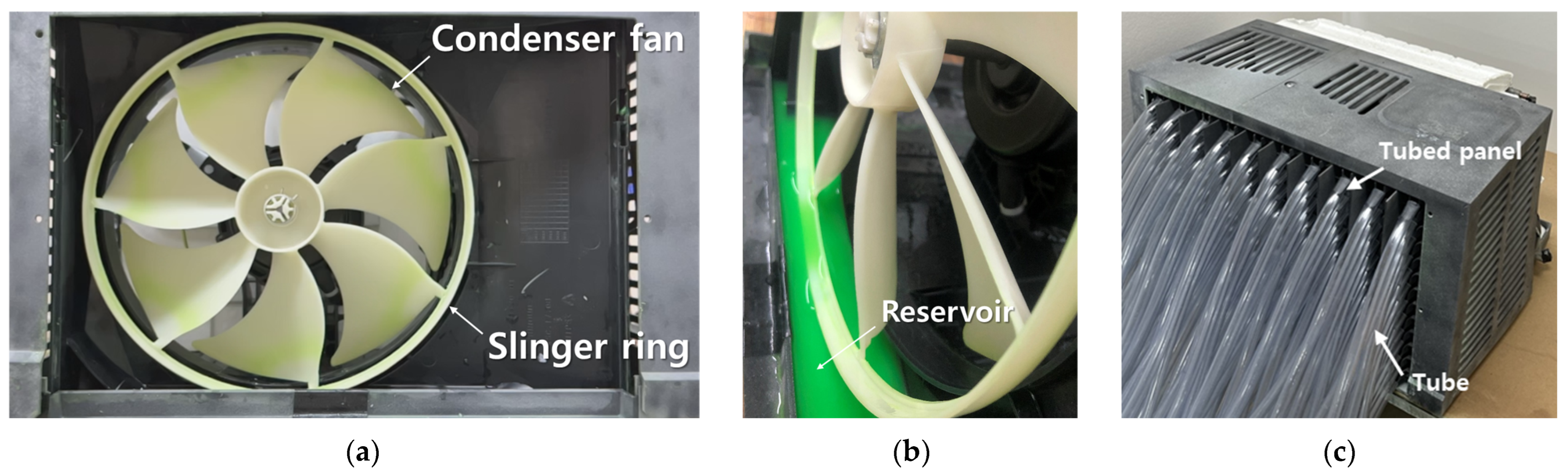
2.2. Experimental Test Facility

The present comparative study between the EFDs and CFDs mainly focused on the condensate distribution and the condensate topologies, which are related to the indicators of the performance of the slinger ring. Therefore, the setup for heat transfer in a WAC is ignored in this study, resulting in the exclusion of the internal flow and the variation in the properties of the refrigerant in the coils. The schematic of the experimental setup is plotted in Figure 4, and the corresponding photographs of the test model are exhibited in Figure 5. The specifications of the components for the experimental model are the same as those of the CFDs, as presented in Table 2. The operation conditions of the EFDs are presented in Table 3.
Two experiments were separately performed. One was to measure the amount of the condensate in each tube, as shown in Figure 5c, to achieve the distribution of the discharged condensate on the inner plane near the condenser coils. The other was to visualize the condensate spray by the slinger ring to understand the condensate distribution on the plane near the condenser coils.
The measurement of the condensate mass discharge can be considered as one of the possible indicators that the efficiency of the slinger ring could be evaluated by a mount of the sprayed or attached condensate on the inner wall and the coils in the condenser. Thus, the condensate distributions on the planes near the condenser coils were achieved by the experiments. The measurement facilities were set up with the tubes, which were connected to the wall near the condenser coils, as shown in Figure 4 and Figure 5c. The condensate accumulated in the tubes by the spray of the slinger ring. The specifications of the tubes are arranged in Table 4.
Another experiment was carried out to visualize the spray of the condensate by the slinger ring, to understand the condensate distribution on the plane near the condenser coils. In order to visualize the splash of the condensate by the slinger ring, a camera was utilized to capture the distribution and the topology change of the condensate liquid by the slinger ring. The evolution of splash was captured by the camera, which was capable of recording 240 frames per second with a resolution of 2532 × 1170 pixels. The holed wall with the tubes, which was used to measure the splashed condensate mass by the slinger ring, was removed to record the dynamic sequences of the variations in the condensate topology by the slinger ring.

3. Results and Discussion

3.1. Condensate Distribution and Discharge of CFDs and EFDs

In order to validate the reliability of the present numerical methods to simulate the multiphase flows in the window air conditioner, a comparison of the CFDs and the experimental results was performed. First, the condensate topologies of the present numerical results were compared with those of the experiment.
Figure 6 presents the front views of the typical distributions of the condensate in the initial period for EFDs and CFDs. Both EFDs and CFDs results revealed the regional dependence of the transportation and transformation of the condensate in the reservoir by the impact of the slinger ring. Both results, of EFDs and CFDs, identified the liquid film and ligaments structures that characterized the condensate topologies in the initial period in the left-corner and side-wall regions. In the region near the top wall, the accumulated condensates moved the right-hand side along the rotational direction of the slinger ring, by centrifugal force. This cohered condensate on the right-side top wall broke into ligaments and, finally, the droplets were freely falling, as shown in Figure 6a,b for EFDs and CFDs, respectively. Therefore, the present CFDs well reconstructed the transformation of the condensate topology of the EFDs in the region near the top wall.
The wide right-side region secured the relatively long distance between the surfaces of the slinger ring and the shroud wall. The present EFDs and CFDs showed similar results for the ligaments and droplets sprayed by the slinger ring, as shown in Figure 6a,b, respectively. These condensates sprayed by the slinger ring flew into wider radial and circumferential distances and reached the region near the right-side wall of the shroud.
The amount of the sprayed condensate can be a possible indicator of the heat-transfer performance of the slinger ring. Thus, the present study measured the total amount of the condensate mass discharge crossing the measurement section near the condenser. The present numerical study followed the same strategy of the experiment to measure the total amount of the condensate mass discharge by the slinger ring. Thus, the present study focused on a comparison of the patterns of the time evolution of the total condensate mass discharge between the EFDs and the CFDs. First, in case of the EFDs, the total condensate mass discharge ( M T ) was evaluated by the summation of the condensate in all the tubes. For the CFDs, the M T was obtained by the surface integration of the local condensate mass discharge. Next, the values of M T for the EFDs and the CFDs were nondimensionalized by the amount of M T at the longest time periods in the present experimental and numerical studies, respectively. In other words, the ratio of M T to the maximum M T was considered and denoted as the mass discharge ratio ( M T , R ). The normalized times for EFDs and CFDs were achieved by each of the end times.
Figure 7 shows the time histories of the mass discharge ratio ( M T , R ) for the CFDs and the EFDs. The EFDs showed the rapid augmentation of M T , R in the initial transient period. The CFDs also provided the initial quick increase in M T , R . However, the gradients of temporal variation of M T , R for the CFDs and the EFDs were quite different. As previously mentioned, this difference can be caused by the initial different rotational speeds of the fan between the CFDs and the EFDs. In contrast to the initial state, the temporal variations of M T , R for the CFDs and the EFDs were in a very similar pattern, with an almost linear increasing behavior to the time; even the slops for the CFDs and the EFDs were slightly different, as shown in Figure 7. The linear increasing behavior to the time can be considered as the steady state. Usually, the fan itself is considered as the steady operating fluid machine. In summary, the temporal variations in M T , R for the CFDs and EFDs revealed two types of temporal evolutions of the rapid increasing and linear increasing behaviors in the initial and steady states, respectively.

3.2. Flow and Thermal Fields

The condensate was mainly sprayed into the outer area of the slinger ring, by the centrifugal force exerted on the condensate by the slinger ring. A large amount of the condensate was distributed in the left-side region between the slinger ring and the wall. Some condensate appeared on the inner surface of the slinger ring and the fan blade surfaces, as shown in Figure 8a. These distributions of the condensate were maintained at the plane near the condenser coil; even the intensity of the mass fraction became weak, as shown in Figure 8b.
The present study considered the results for the steady state. In order to define these 3D vortical structures, the present study adopted the swirl strength provided by Zhou et al. [13]. They defined a vortical region as a region with negative λ 2 , the second largest eigenvalue of S i j 2 + Ω i j 2 , where S i j 2 and Ω i j 2 are the strain-rate tensor and rotation-rate tensor, respectively.
Figure 9a,b shows the three directional vortical structures for the multiphase and single-phase flows, respectively. Generally, the flow fields for the multiphase fluids installed in the slinger ring were almost the same as the single-phase flow of the air without the condensate. Specifically, the large circumferential tube structures appeared near the blade tips and the slinger ring surface and were almost independent of the time, since the fan is commonly considered as the steady operation fluid machine. When the flow reached the statistically steady state, other vortical structures vorticities were split into small vortices. Also, the flow became fully turbulent and its scale became smaller, which contributed to forming the small-scale strong shear flow.
However, in the left-side lower region, where the large amount of condensates was sprayed by the slinger ring, as shown in Figure 8, the multiphase flow revealed more small-scale vortical structures related to stronger shear flow rather than to single-phase flow, which can be clarified by comparing the 3D vortical structures between the multiphase and single-phase flows shown in Figure 9a,b, respectively.
The corresponding flow and the thermal fields to the distributions of the condensate mass fraction are presented in Figure 10 and Figure 11, respectively. The high-speed flows appeared in the inner region of the slinger ring and fan, regardless of the axial planes and the fluid phase, as shown in Figure 10. Therefore, the intake air with relatively high temperature occupied this region. Therefore, the air with relatively high temperature was sucked into this region and blew toward the condenser coils. As a result, the forced convection was very strong in this region. The corresponding flow and the thermal fields to the distributions of the condensate mass fraction are presented in Figure 10 and Figure 11, respectively.
The high-speed flows appeared in the inner region of the slinger ring and fan, regardless of the axial planes and the fluid phase, as shown in Figure 10. Therefore, the intake air with relatively high temperature occupied this region. Therefore, the air with relatively high temperature was sucked into this region and blew toward the condenser coils. As a result, the forced convection was very strong in this region.
However, this strong rotation and axial flow protected the entrainment of the splayed condensate with the relatively lower temperature. Hence, when the singer ring was utilized to enhance the heat transfer, this inner region of the slinger ring and fan had the very weak advantage of the condensate splay, resulting in the relatively low efficiency of the heat transfer. In this inner region, the relatively high-temperature distribution, as shown in Figure 11a,b, clearly supports this weak heat transfer in the inner region of the fan and the slinger ring.
The low-temperature distribution was concentrated near the left-side wall and the gap between the slinger ring and the left-side wall, as shown in Figure 11a,b. The low-temperature distribution was naturally governed by the distribution of the splashed cold condensate.
As the plane was closer to the condenser coils, the region of the low-temperature distribution became smaller because of the reduction in the distributed area and the amount of the sprayed condensate with the low temperature, as shown in Figure 11b. Some condensate sprayed by the slinger ring reached the condenser coils, as shown in Figure 8b, which contributed to the enhancement of the heat transfer by the reduction of the temperature of the coils, as shown in Figure 11b. As the plane became more distant from the fan center, the velocity vectors in the right side between the slinger ring and the shroud wall were more unstable and formed the complex secondary vortical flow, as shown in Figure 10b. Thus, the mixing effect contributed to enhancing the cooling in this region, resulting in the temperature drop in this right-side region, as shown in Figure 11a,b.
The region near the left-side wall revealed that the widest area was exposed to the splashed condensate by the slinger ring, as shown in Figure 12a, which was consistent with the axial plane distributions of the sprayed condensate, as shown in Figure 8. The condensate was splashed to almost all the condenser coils in this left-side region near the shroud wall, as shown in Figure 12a. This wide distribution of the splashed condensate contributed to cooling the inner fluid temperature and the coils, as shown in the isothermal distribution in Figure 13a.
For the planes in the inside region of the slinger ring and the fan, the splashed condensates were mainly distributed near the top wall by the centrifugal forces of the slinger ring, as shown in Figure 12b. Thus, the cooling was limited in the top wall, resulting in the appearance of lower temperatures in this top wall, as shown in the isothermal distribution in Figure 13b.
The right-side plane was partially covered with the splashed condensates by the centrifugal force of the slinger ring, as shown in Figure 12c. As shown in the axial plane in Figure 10, the fan center plane was affected by the strong axial flow shown in Figure 14b,e restricting the entrainment of the spayed condensates and resulting in a negligible cooling effect, with about the same isothermal distribution as that with the single-phase flow, as shown in Figure 13c,f for the multiphase and single-phase flows, respectively.
The reverse flows occurred in the regions near the top and side walls, as shown in Figure 14a,c. These circulating flows carried hot fluids attached to the upper hot coils in the inner region and increased the inner fluid temperature. Therefore, the upper region near the top wall was covered by hot temperatures, as shown in Figure 13.

3.3. Heat-Transfer Rate

Figure 15 shows the distribution of the heat-transfer rate on the surfaces of the shroud, the slinger ring, and the fan for the single-phase flow of the air and the multiphase flow with the air and the condensate. The thermal boundary conditions on the walls of the single-phase flow with the air had the same isothermal condition as the inlet condition, except for the condenser coils. Thus, there was almost no heat transfer on the walls, except for the condenser coils, leading to the zero value of the heat transfer, as shown in Figure 15a.
Figure 15b shows the distribution of the heat-transfer rate on the walls by the condensate splashed by the slinger ring. The condensate sprayed by the slinger ring caused a considerable heat transfer on the walls, as shown in Figure 15b. The regions of the occurrence of the heat transfer exactly overlapped those of the condensate spray, as previously exhibited and discussed in Figure 8 and Figure 10. Therefore, the strong heat transfer appeared on the left-side shroud wall, the left top wall, and the right-side lower wall, as shown in Figure 15b. In addition, the left-half surface of the slinger ring and the left-side surface of fan blades near the tips. In particular, the cold condensate in the reservoir cooled the walls and the surrounding hot air near the reservoir. Therefore, this distribution of the heat-transfer rate on the walls distinctly confirmed that the slinger ring enhanced the performance of heat retransfer by spraying the condensate.
The heat-transfer rate on the condenser coils can be considered as the most important indication of the performance of the slinger ring, which sprayed the condensate in the reservoir. The distributions of the heat-transfer rate on the inner and outer surfaces of the condenser coils for the single- and multi-phase flows are presented in Figure 16.
The isothermal conditions with different temperatures were applied on the condenser coils. The condenser coils with higher temperatures than the inlet temperature of the air are located over the dashed line marked in Figure 16. Thus, the hot condenser coils were cooled by the heat loss to the air, resulting in the appearance of negative heat-transfer rates on the condenser coils over the dashed line, as shown in Figure 16a. This heat transfer was expected by the difference in the boundary conditions.
In contrast to the single-phase flow, the multiphase flow with the condensate in the reservoir gained the additional regions exposed to the heat transfer, since the cold condensates splashed by the slinger ring caused the additional heat transfer on wider condenser coils, as shown in Figure 16b. The additional coils with the heat transfer are identified by the areas exposed to the sprayed condensate, as previously exhibited and discussed in Figure 8, which is consistent with the distribution of the heat-transfer rate on the walls of the shroud, slinger ring, and fan shown in Figure 16b.
Finally, the total heat-transfer rates of the multiphase flow by the slinger ring and the single-phase flow with the air were computed by integrating the local heat-transfer rate on the coil surfaces. The slinger ring contributed to a significant increase of approximately 17% in the heat transfer on the condenser coils, compared with the single-phase flow. The coils submerged in the reservoir were extracted to compute the total heat-transfer rate, to evaluate the net effect of the sprayed condensate by the slinger ring.

4. Conclusions

The present study evaluated the effect of the slinger ring on the forced convection heat transfer in window air conditioners (WACs) for the heat-transfer enhancement. Numerical simulations were initially performed to solve the complex multiphase flow with the rotating bodies by using the volume of fluid (VOF) and slide mesh. In addition, the single-phase fluid flow and the heat transfer were numerically simulated to compare the heat-transfer performance of the multiphase flow derived by the slinger ring. For the purpose of validating the numerical results, experiments were performed.
The EFDs visualized the condensate distribution and measured the condensate mass discharge crossing the section near the condenser. The EFDs showed that the condensate topologies are dependent on the local regions. Also, the EFDs provided the sequence of the topology change, in that the liquid sheet was torn as the ligaments became thinner and were broken into droplets. The CFDs results constructed qualitatively well these transformations of the condensate by the slinger ring observed from the EFDs. The CFDs and EFDs results presented almost the same condensate distribution, which appeared mainly out of the slinger ring by the centrifugal force. The temporal variations in the total condensate mass discharge for the CFDs and EFDs revealed about the same two types of temporal evolutions of the rapid and linear increasing behaviors in the initial and steady states, respectively. As a result, both qualitive and quantitative comparisons between the EFDs and CFDs results yielded good agreement, which guaranteed the reliability of the present numerical methods.
The low-temperature distribution was concentrated near the left-side wall and the gap between the slinger ring and the left-side wall, which was governed by the distribution of the splashed cold condensate by the slinger ring. The condensate was splashed to almost all the condenser coils in this left-side region near the shroud wall, leading to cooling the inner fluid and the coils.
However, the strong axial flow occurred in the inner region of the slinger ring and fan, which protected the entrainment of the splashed condensate with a low temperature in this region. Thus, this inner region of the slinger ring and the fan had the very weak advantage of the slinger ring, resulting in the relatively low efficiency of the heat transfer. The appearance of the unstable vortical flows in the right-side region appeared to contribute to the mixing effect, which enhanced the cooling in this region between the slinger ring and the shroud wall.
The slinger ring caused the considerable heat transfer on the walls and the condenser coils by spraying the condensates, compared to the single-phase flow. The regions of the occurrence of the heat transfer exactly overlapped with those exposed to the condensates sprayed by the slinger ring. The slinger ring contributed to a substantial increase of approximately 17% in the heat transfer on the condenser coils, compared with the single-phase flow.
The present study confirmed that the slinger ring enhances heat-transfer performance by spraying the condensate, in comparison with the heat transfer by the single-phase flow. The present study identified the area exposed to the sprayed condensate by the slinger ring. The enlargement of the wetted area of the sprayed condensate is essential to enhance the performance of the heat transfer. In future research, the fins of the condenser coils and the evaporation of the compensate will be considered, to more exactly evaluate the effect of the slinger ring on the heat-transfer performance in a WAC.

Author Contributions

Conceptualization, C.-H.C.; writing—original draft, C.-H.C.; resources, D.-K.J., D.-H.K., H.-C.P. and J.-H.L.; methodology, D.-K.J., D.-H.K., H.-C.P. and J.-H.L.; investigation, D.-K.J., D.-H.K., H.-C.P. and J.-H.L.; project administration, M.-Y.H.; supervision, H.-S.Y.; writing—review and editing, H.-S.Y.; visualization, M.-I.K. and S.-B.H.; validation, M.-I.K. and S.-B.H. All authors have read and agreed to the published version of the manuscript.

Funding

This work was supported by the Korea Institute of Energy Technology Evaluation and Planning (KETEP) and the Ministry of Trade, Industry & Energy (MOTIE) of the Republic of Korea (No. 20224000000090) and by the National Research Foundation of Korea (NRF) grant funded by the Korean government (MSIT) through NRF-2019R1A2C1009081.

Institutional Review Board Statement

Not applicable.

Informed Consent Statement

Not applicable.

Data Availability Statement

Data are contained within the article.

Conflicts of Interest

Authors Chin-Hyuk Chang, Dae-Kwon Jeong, Dae-Hyeok Kim, Hyun-Cheol Park, Jong-Ho Lee were employed by the company LG Electronics. The remaining authors declare that the research was conducted in the absence of any commercial or financial relationships that could be construed as a potential conflict of interest.

Nomenclature

t Time
x i Cartesian coordinates
u i , u j Velocity components
p Pressure
T Temperature
C p Specific heat capacity
k Thermal conductivity
F External body force
Q h Volume fraction
W Width
H Height
B Breadth
L Length
n Rotational speed
D Fan diameter
r Fan radius
R e Reynolds number (= π n D r / )
M T Total condensate mass discharge
M T , R Mass discharge ratio
λ 2 Second largest eigenvalue
S i j 2 Strain rate tensor
Ω i j 2 Rotation rate tensor
Greek symbols
ρ Density
μ Dynamic viscosity
ν Kinematic viscosity
Superscripts
¯ Time-averaged quantity
Abbreviations
WACWindow air conditioner
VOFVolume of fluid
CFDComputational fluid dynamics
EFDExperimental fluid dynamics
3DThree dimensional
SIMPLECSemi-implicit method for pressure-linked equation-consistent
rpsRevolutions per second

References

  1. Falkovich, G.; Fouxon, A.; Stepanov, M.G. Acceleration of rain initiation by cloud turbulence. Nature 2002, 419, 151–154. [Google Scholar] [CrossRef] [PubMed]
  2. Bansal, P. High efficiency novel window air conditioner. Appl. Energy 2015, 156, 311–320. [Google Scholar] [CrossRef]
  3. Shen, B.; Bansal, P. Assessment of Environmentally Friendly Refrigerants for Window Air Conditioners. In Proceedings of the Name of the International Refrigeration and Air Conditioning Conference, West Lafayette, IN, USA, 14–17 July 2014. [Google Scholar]
  4. Shen, B.; Fricke, B. Development of high efficiency window air conditioner using propane under limited charge. Appl. Therm. Eng. 2020, 166, 114662. [Google Scholar] [CrossRef]
  5. Lawrence Livermore National Laboratory. Technical Support Document for Energy Conservation Standards for Room Air Conditioners: Volume 2—Detailed Analysis Of Efficiency Levels; Docket Numbers EE-RM-90-201 & EE-RM-93-801-RAC; Lawrence Livermore National Laboratory: Livermore, CA, USA, 1997. [Google Scholar]
  6. Hirt, C.W.; Nichols, B.D. Volume of fluid (VOF) method for the dynamics of free boundaries. J. Comput. Phys. 1981, 39, 201–225. [Google Scholar] [CrossRef]
  7. Siemens. STAR-CCM+ User Guide Version 16.04; Siemens: New York, NY, USA, 2016. [Google Scholar]
  8. Meinke, M.; Schneiders, L.; Gunther, C.; Schröder, W. A cut-cell method for sharp moving boundaries in Cartesian grids. Comput. Fluids 2013, 85, 135–142. [Google Scholar] [CrossRef]
  9. Mathur, S. Unsteady flow simulations using unstructured sliding meshes. In Proceedings of the Fluid Dynamics Conference, Colorado Springs, CO, USA, 20–23 June 1994. [Google Scholar]
  10. Blades, E.L.; Marcum, D.L. A sliding interface method for unsteady unstructured flow simulations. Int. J. Numer. Methods Fluids 2007, 53, 507–529. [Google Scholar] [CrossRef]
  11. Hundshagen, M.; Skoda, R. State of the Art on Two-Phase Non-Miscible Liquid/Gas Flow Transport Analysis in Radial Centrifugal Pumps Part C: CFD Approaches with Emphasis on Improved Models. Int. J. Turbomach. Propuls. Power 2023, 8, 15. [Google Scholar] [CrossRef]
  12. Hynninen, A.; Vitanen, V.; Tanttari, J.; Klose, R.; Testa, C.; Martio, J. Multiphase Flow Simulation of ITTC Standard Cavitator for Underwater Radiated Noise Prediction. J. Mar. Sci. Eng. 2023, 11, 820. [Google Scholar] [CrossRef]
  13. Zhou, J.; Adrian, R.J.; Balachadar, S.; Kendall, T.M. Mechanisms for generating coherent packets of hairpin vorticies in channel flow. J. Fluid Mech. 1999, 387, 353–396. [Google Scholar] [CrossRef]
Figure 1. (a) Schematics of WAC and (b) components of an outdoor unit of a WAC as the computational model.
Energies 16 07947 g001
Figure 2. (a) Boundary conditions (Blue: inflow, Red: Outflow) and (b) temperature distribution on the surfaces of coils as the thermal boundary condition.
Energies 16 07947 g002
Figure 3. Grid system: (a) perspective view, (b) top view, and (c) side view.
Energies 16 07947 g003
Figure 4. Schematic of the experimental setup.
Energies 16 07947 g004
Figure 5. (a) Front and (b) perspective views of the experimental model and (c) perspective view of the measuring devices for the condensate mass discharge.
Energies 16 07947 g005
Figure 6. Typical transformation of the condensate by the slinger ring in the initial transitional states for (a) EFDs and (b) CFDs.
Energies 16 07947 g006
Figure 7. Time variation of the mass discharge ratio ( M T , R ) for EFDs and CFDs.
Energies 16 07947 g007
Figure 8. Distributions of the volume fraction of the condensate in different axial planes of centers of (a) the fan and (b) the condenser coils.
Energies 16 07947 g008
Figure 9. Three directional vortical structures for (a) the multiphase flow and (b) the single-phase flow.
Energies 16 07947 g009
Figure 10. Velocity vectors colored with the velocity magnitudes for (a,b) the multiphase flow and (c,d) the single-phase flow in different axial planes of centers of the fan (a,c) and condenser coils (b,d).
Energies 16 07947 g010
Figure 11. Temperature contours for (a,b) the multiphase flow and (c,d) the single-phase flow in different axial planes of centers of the fan (a,c) and condenser coils (b,d).
Energies 16 07947 g011aEnergies 16 07947 g011b
Figure 12. Distributions of condensate volume fraction in different vertical planes (a) near the left-side wall, (b) at the fan center, and (c) between the slinger ring and the right-side wall.
Energies 16 07947 g012
Figure 13. Temperature contours for the multiphase (left column: ac) and single-phase (right column: df) flows in different vertical planes (a,b) near the left-side wall, (c,d) at the fan center, and (e,f) between the slinger ring and the right-side wall.
Energies 16 07947 g013aEnergies 16 07947 g013b
Figure 14. Velocity vectors colored by the velocity magnitudes for the multiphase (left column: ac) and single-phase (right column: df) flows in different vertical planes (a,b) near the left-side wall, (c,d) at the fan center, and (e,f) between the slinger ring and the right-side wall.
Energies 16 07947 g014aEnergies 16 07947 g014b
Figure 15. Distributions of the heat-transfer rate on the surfaces of the shroud, slinger ring, and fan for (a) the single-phase flow of the air and (b) the multiphase flow of the air and the condensate.
Energies 16 07947 g015
Figure 16. Distributions of the heat-transfer rate on the inner surface of the condenser coils for (a) the single-phase flow and (b) the multiphase flow.
Energies 16 07947 g016
Table 1. Properties of condensate and air.
PropertiesValue
CondensateAir
Density (kg/m3)997.561.18
Viscosity (Pa·s) 8.88   × 10−4 1.85   × 10−5
Specific heat (J/kg·K)4181.721003.62
Thermal conductivity (W/m·K)0.62020.0260
Table 2. Component specifications of outdoor unit.
ComponentsSpecifications
Outdoor cover435.4 mm (W) × 281.2 mm (H) × 239.33 mm (B)
Number of holes: 83
Motor 200.0   mm   ( L )   × 106.6 (D)
Compressor 88.2   mm   ( L )   × 96.4 (D)
Condenser fanNumber of blades: 7
Diameter: 123 mm
Slinger ringDepth: 10 mm
Diameter: 133 mm
Condenser369 mm (W) × 279.2 mm (H) × 19.77 mm (B)
Number of coils: 83
Number of rows in depth direction: 2
Number of coils per row: 14
Horizontal coil spacing: 5 mm
Vertical coil spacing: 150 mm
Coil diameter: 5 mm
Table 3. Initial and boundary condition for CFDs.
BoundariesConditions
InletPressure inlet (atmosphere),
Temperature (35 °C)
OutletOutflow
Condensate supplyMass flow rate (0.62 kg/h),
Temperature (24 °C)
WallNo-slip,
Temperature (35 °C)
CoilNo-slip
Temperature (35~70 °C)
Initial filling height of condensate reservoir9 mm
Table 4. Test conditions and specifications.
ComponentsConditions/Specifications
Fan speed1435 rpm
Initial filling height9 mm
Condensate supply0.62 kg/h
TubesNumber of rows: 10
Number of columns: 13
Tube inside diameter: 8 mm
Disclaimer/Publisher’s Note: The statements, opinions and data contained in all publications are solely those of the individual author(s) and contributor(s) and not of MDPI and/or the editor(s). MDPI and/or the editor(s) disclaim responsibility for any injury to people or property resulting from any ideas, methods, instructions or products referred to in the content.

