Review

Solar-Powered Water Electrolysis Using Hybrid Solid Oxide Electrolyzer Cell (SOEC) for Green Hydrogen—A Review

by
Shammya Afroze
1,*,
Amal Najeebah Shalihah Binti Sofri
2,
Md Sumon Reza
3,4,
Zhanar Baktybaevna Iskakova
3,
Asset Kabyshev
1,
Kairat A. Kuterbekov
1,*,
Kenzhebatyr Z. Bekmyrza
1,*,
Lidiya Taimuratova
5,
Mohammad Rakib Uddin
6 and
Abul K. Azad
2
1
Faculty of Physics and Technical Sciences, L.N. Gumilyov Eurasian National University, Astana 010008, Kazakhstan
2
Faculty of Integrated Technologies, Universiti Brunei Darussalam, Jalan Tungku Link, Gadong BE1410, Brunei
3
Research Institute of New Chemical Technologies, Faculty of Natural Sciences, L.N. Gumilyov Eurasian National University, Astana 010008, Kazakhstan
4
Department of Biological & Agricultural Engineering, North Carolina State University, 3110 Faucette Dr., Raleigh, NC 27695, USA
5
Faculty of Science and Technology, Caspian University of Technology and Engineering Named After Sh. Yessenov, Microdistrict 32, Aktau 130000, Kazakhstan
6
College of Nano Science and Engineering, State University of New York Polytechnic Institute, Albany, NY 12203, USA
*
Authors to whom correspondence should be addressed.
Energies 2023, 16(23), 7794; https://doi.org/10.3390/en16237794
Submission received: 11 September 2023 / Revised: 14 November 2023 / Accepted: 23 November 2023 / Published: 27 November 2023
(This article belongs to the Collection Current State and New Trends in Green Hydrogen Energy)

Abstract

:
The depletion of fossil fuels in the current world has been a major concern due to their role as a primary source of energy for many countries. As non-renewable sources continue to deplete, there is a need for more research and initiatives to reduce reliance on these sources and explore better alternatives, such as renewable energy. Hydrogen is one of the most intriguing energy sources for producing power from fuel cells and heat engines without releasing carbon dioxide or other pollutants. The production of hydrogen via the electrolysis of water using renewable energy sources, such as solar energy, is one of the possible uses for solid oxide electrolysis cells (SOECs). SOECs can be classified as either oxygen-ion conducting or proton-conducting, depending on the electrolyte materials used. This article aims to highlight broad and important aspects of the hybrid SOEC-based solar hydrogen-generating technology, which utilizes a mixed-ion conductor capable of transporting both oxygen ions and protons simultaneously. In addition to providing useful information on the technological efficiency of hydrogen production in SOEC, this review aims to make hydrogen production more efficient than any other water electrolysis system.

1. Introduction

The speed of energy transformation is accelerating globally due to the need to curb climate change and achieve sustained growth in a time of rapid change [1]. Currently, the challenges posed by global warming, the fluctuating price of oil, and the depletion of fossil fuels are the primary forces affecting the research and understanding of the conversion and use of renewable energy [2]. Converting energy from fossil fuels to clean energy is essential for the safety of the energy supply of the country [3,4]. In the first decade of the twentieth century, coal dominated the market for fuels, but by 1920, oil was gaining ground as a heating or transport fuel on land and sea. Hydrogen, which has a high energy density and eco-friendly qualities, is one of the most promising energy sources for producing electricity from fuel cells and heat engines without releasing CO2 or other pollutants [5,6]. In this new era, there is a high demand for hydrogen mainly in the refining and industry sector, while almost all of its manufacture is made from coal. This led to massive CO2 emissions. The International Energy Agency (IEA) estimates that in order to reach net zero emissions by the year 2050, the global energy system would need 520 million tonnes of “low carbon” hydrogen annually [7]. This transformation is driven by the sharp drop in renewable energy costs, rising energy efficiency, broad electrification, increasingly intelligent technology, ongoing technical advancements, and educated policy-making, which puts a sustainable energy future within grasp. In 2050, energy commodities are expected to increase from USD 1.5 trillion in 2020 to USD 1.6 trillion [7]. Biofuels and hydrogen are among the major drivers of this increase in renewables. In order to meet the rising demand for electricity, the power grids will almost double from 2020 to 2050, and renewable energy technologies are going to be a major source of new capacity.
Hydrogen may eventually rule the energy market in the years to come [8]. As a result, the production of hydrogen has received considerable interest [9]. Through electrolysis, renewable energy may be transformed into power and green hydrogen [10]. Almost all of the hydrogen produced, about 70 million tons per year, is now powered by fossil fuels, which account for about 6% of global natural gas demand and 2% for coal [11]. However, building electrolyzers to produce hydrogen from solar and wind energy offers a clean and affordable option, even when taking into account the cost of delivering hydrogen to consumers or end users due to the lower cost of renewable energy production [12]. When considering how to employ hydrogen as an energy storage medium, its low volumetric energy density is an issue to take into account, although it is not always a deal-breaker. Gaseous hydrogen has a volumetric energy density of 0.09 kg/m3 at atmospheric pressure. By employing high-pressure tanks to store hydrogen gas, which increases the amount of energy that can be stored in a given container, this low volumetric energy density of hydrogen may be addressed.
Fueled by hydrogen, the shift to complete decarbonization will be crucial [13]. However, for hydrogen to meet carbon emission reduction targets, it must be produced from renewable energy rather than fossil fuels [14]. Using water and renewable energy sources like solar energy to burn hydrogen will undermine its clean combustion rate due to its high energy density of 120 kJ/g as compared to the use of fossil fuels [15,16]. Recent developments in the direct synthesis of hydrogen from seawater, which might serve as an endless supply of environmentally friendly hydrogen, were reported by a number of research groups. Although seawater is almost infinite, separating it has its own set of issues. However, when seawater is used, chloride ions in seawater are converted into highly corrosive chlorine gas, which eats away at the electrodes and catalysts by the same electrical shock that generates O2 in the anode. The study of solar energy to desalinate seawater, which later produces hydrogen, was carried out to optimize targets and improve efficiency [17]. This approach maintains a consistent flow of clean water into the electrodes while preventing the ions and other pollutants in the saltwater outside the membrane from entering the electrodes, which is the preferred low-cost system. As renewable energy is on the rise to reduce fossil fuel pollutants, several projects have been undertaken to generate green hydrogen using extra renewable energy.
The concept of deploying so-called “green hydrogen” is gaining momentum among companies around the world who grasp the opportunity to produce hydrogen directly from solar panels without using electricity from the grid. An electrolyzer may be powered by solar energy to convert water into hydrogen [18]. This is an energy-intensive electrolysis process that has so far prevented widespread deployment [19]. Solar energy is on the rise as a low-cost power source for producing green hydrogen [20]. The tremendous amount of energy that the sun emits each day in the form of heat and radiation is known as solar energy [21]. Solar energy is one of several ecologically beneficial and clean energy sources, and it is abundant [22]. When compared to the various fossil fuels and oil during the past ten years, one of the most significant advantages of solar energy is that it is inexpensive, widely accessible, and capable of meeting energy demands [23].
A floating solar energy device for producing hydrogen was developed by startup solar marine energy for coastal and island regions [24]. A firm, EI-H2, revealed plans in May for a 50 MW green hydrogen plant in Cork, Republic of Ireland, that would start producing 20 tons per day of green hydrogen from surplus wind energy in 2023 [25]. Additionally, it teamed up with fuel manufacturer Zenith Energy in July to create a 3.2 GW green hydrogen and ammonia project that will begin operating from offshore wind in 2028 [26].
Nevertheless, a substantial change is needed in the global energy system from one that largely depends on oil and gas to one that improves efficiency but also relies on renewables [27]. The hybrid SOEC operating system allows for water electrolysis at both air and hydrogen electrodes since the electrolyzed ions O2− and H+ may be counter-diffused through the mixed ionic conducting electrolyte in the opposite direction with record-breaking electrochemical performance in producing hydrogen. Furthermore, the concept behind the investigation on the hybrid SOEC based on the mixed ionic conducting electrolyte is novel because very little research has been conducted in this area. This article aims to study the hybrid SOEC-based solar hydrogen-generating technology by providing important knowledge on the technological capabilities of SOEC-based hydrogen generation. This review intends to summarize the development of solar-powered hybrid SOECs, offer a thorough introduction to hybrid systems, analyze scenarios and novel approaches, and evaluate the cost evolution and commercialization based on the research on hybrid SOECs.

2. Electrolysis

Electrolysis is a possible replacement for the production of carbon-free hydrogen using nuclear and renewable energy sources. Water splits into hydrogen and oxygen via the process of electrolysis [28]. This reaction takes place in a device known as an electrolyzer. An electrolyzer can range in size from tiny appliances that are ideal for producing hydrogen on a small scale and in various locations to enormous central production facilities that could be directly connected to energy sources that do not produce greenhouse gases [29]. The anode and the cathode of electrolyzers are separated by an electrolyte, much like in fuel cells [30]. A membrane, which is capable of applying a high voltage and current, separates the conductive stack electrode. Electrolysis occurs when an electrical current travels through the electrolytes. The oxygen produced concurrently is released into the environment or, in certain situations, can be saved for later use as a medicinal or industrial gas. For use in industry or hydrogen fuel cells that can be connected to transport vehicles, like trains, ships, and even aircraft, hydrogen is stored as a compressible gas or liquid. The significance of this procedure, which enables energy to be used to break down molecules—in this example, water molecules—is crucial for producing green hydrogen. Thus, hydrogen can be produced from electrolysis and the hydrogen is categorized into various colors, including blue, grey, turquoise, yellow, pink, and green, depending on their techniques for producing hydrogen and their characteristics, as explained in Table 1.
Different electrolyzers work differently owing to the various electrolyte materials used and the ionic species they conduct [35]. In diverse electrolysis techniques, three distinct electrolyzers—polymer electrolyte membrane electrolyzers, alkaline electrolyzers, and solid oxide electrolyzers—are employed [36]. Solid oxide electrolyzers are used to produce hydrogen because they can reduce the amount of electrical energy required to produce hydrogen from water due to the heat produced at their high operating temperatures [37].

3. Solid Oxide Electrolysis

3.1. History of Solid Oxide Electrolysis

In the 1980s, Dönitz and Erdle were pioneers in the development of solid oxide electrolysis [38]. This approach generated a lot of interest since it efficiently produces pure hydrogen while converting electrical energy into chemical energy. High pressures and temperatures are required for solid oxide electrolysis to occur, as depicted in Figure 1, which gives a schematic overview of the procedure. It differs from conventional methods by employing steam instead of water as the ionic agent, which is typically produced by using yttria-stabilized zirconia [39]. The operational theory of solid oxide electrolysis and alkaline electrolysis are fairly similar, with the half-reaction equations being the only significant difference [14].
Reaction equations:
Cathode :   H 2 O + 2 e H 2 + O 2
Anode :   O 2 1 2 O 2 + 2 e

3.2. Solid Oxide Electrolysis Cells

As a commercial product, the solid oxide electrolysis cell (SOEC), a green hydrogen-generating technique, is still in its infancy [40]. For electrolysis, a stack of solid oxide fuel cells (SOFCs) typically operates in regenerative mode or backward. SOECs generate hydrogen from electricity as opposed to SOFCs, which store electric energy [41]. SOFCs or micro-tubular solid oxide fuel cells (MT-SOFCs) are energy conversion technologies with high conversion efficiencies that convert chemical energy into electricity that is also environmentally beneficial [42,43,44,45]. This electrolysis procedure splits water into hydrogen (H2) and oxygen (O2) while operating at high temperatures and hence with great efficiency [46]. Utilizing excess power generated by wind turbines as well as other environmentally beneficial sources, SOECs may generate green hydrogen [47]. When production outpaces demand, this hydrogen may be safely stored in fuel cells for eventual conversion into electricity, as needed [48]. Because they have a lower equilibrium potential and faster reaction kinetics, SOECs are more efficient [49]. Therefore, SOEC-based water electrolysis is economical, environmentally benign, and has the potential to be very effective in producing hydrogen [50].

4. Solar Hydrogen Generation System

4.1. State-of-the-Art of Electrolysis

High-temperature SOEC was evaluated as the most suitable method to produce hydrogen from industrial waste heat since it offers a wider range of possibilities than current techniques intended for this purpose [51]. It was produced utilizing the most up-to-date techniques and technology. Compared to low-temperature PEM electrolyzers and alkaline electrolyzers, high-temperature SOECs are more efficient because they can generate hydrogen at a higher chemical reaction rate while using less electrical energy [52]. The US Department of Energy (DOE) has launched many programs in recent years to advance SOEC hydrogen generation technology [53].
The following is an expression of the energy required overall for SOEC hydrogen generation [54]:
H = G + T S
where ∆G is the demand for electrical energy, which is a free Gibson energy shift, and T∆S is the demand for thermal energy (J/mol H2). The total amount of energy required for SOEC hydrogen production by showing the predicted energy needs with temperature changes is illustrated in Figure 2. As the operating temperature rises, there is a noticeable increase in the demand for thermal energy but a large decrease in the requirement for electrical energy. On the total amount of energy used, the operating temperature has no bearing. High-temperature SOEC is advantageous since it provides more possibilities for using industrial waste heat for hydrogen generation [55].
For effective and affordable hydrogen generation, the SOEC components must operate at high temperatures and follow the following rules [56].
To obtain high energy conversion efficiency, the dense electrolyte needs to be strongly ionic conductive, chemically stable, and have low electronic conductivity because electronic conduction reduces the ionic conductivity of the electrolyte and current efficiencies of the cell.
For the purpose of lowering the ohmic overpotential, the dense electrolyte should be as thin as feasible, but it must be gastight to completely rule out the possibility of H2 and O2 recombination.
Both electrodes must exhibit high electrical conductivity and chemical resistance under substantially reducing or oxidizing circumstances.
To permit gas movement between the electrode surface and the electrode–electrolyte interface and to establish a trustworthy electrolyte–electrode–gas triple-phase barrier (reaction sites), each electrode should have an appropriate amount of porosity and pore size.
To avoid the electrolyte failing owing to extremely high mechanical stress brought on by an imbalance between the two electrodes, the thermal expansion coefficient (TEC) of the two electrodes should be near to those of the electrolyte.
Materials are needed for interconnects in massive hydrogen production facilities. Since the connecting materials are simultaneously exposed to hydrogen/steam and oxygen, they must be chemically stable under reducing/oxidizing conditions.
The production procedure should be as inexpensive as feasible.

4.2. Solid Oxide Electrolysis Process

Using power supplied from renewable sources, water is electrolyzed to make green hydrogen [57]. An electrochemical energy conversion cell, the solid oxide electrolyzer or solid oxide steam electrolyzer, converts electrical energy from moving electrons to the chemical energy of a fuel [58]. Electrochemical processes at SOEC can generate hydrogen, carbon monoxide, or a combination of the two [59]. As long as steam, carbon dioxide, and electrical energy are provided, it keeps delivering the fuel. In actuality, the lifespan of a cell is constrained by the deterioration of its constituent parts [60]. The foundation of a conventional SOEC is a solid electrolyte that serves as a pure ionic conductor [61]. The most popular type is yttria-stabilized zirconia (YSZ), which, when polarized by using an electrical field, enables oxygen ion movement [62].
Co-ionic cells and proton-conducting cells, in which oxygen and hydrogen ions, or simply hydrogen ions, are transmitted via the membrane, are other less prevalent forms of SOECs [63]. A closed electrical circuit is made by sandwiching the solid electrolyte between two porous electrodes that are electrically linked [64,65]. Each finished cell also includes interconnects and gas passages in addition to the PEN assembly, which stands for positive electrode-electrolyte-negative electrode [66].
Noting that SOEC is composed entirely of solid parts, it is theoretically possible to form it to any requirements. These cells can be linked in series to create a stack similar to SOFC [67]. With SOFC, SOECs have exceptional operational efficiency and design flexibility [68]. The same cell can be operated in SOEC or SOFC mode within a specific polarization range due to the stage of cell development at which it is at the moment [69]. This presents intriguing opportunities for the solid oxide cell (SOC) to be used to alter the energy landscape [70].
Despite its complexity, SOEC operation is rather simple to describe. The fuel electrode on the cathode side of the cell receives steam and carbon dioxide; gases travel through the porous electrode to the triple-phase boundary, where reactions and charge transfer cause the gases to split into hydrogen and carbon monoxide, and oxygen ions are delivered to the anode side of the cell through the electrolyte [71]. Through a process known as the Faradic reaction, anions are split into oxygen molecules and electrons [72]. While electrons travel via the external circuit and are injected into the cathode, completing the circuit, oxygen gas diffuses to the anode gas chamber [73]. A cell can generate both heat and chemical fuel if it is run at a high enough voltage. A typical SOEC operates in a temperature range of 500 °C to 1000 °C at atmospheric or elevated pressures [74].

4.3. Solar-Powered Hybrid SOEC

The fusion of SOEC and concentrated solar power (CSP) yields state-of-the-art solar hydrogen technology [75]. The CSP plant can satisfy both the electric and thermal energy needs of the SOEC from a single location by providing electricity and high-temperature heat. The production of hydrogen using concentrated solar energy and high-temperature electrolysis is interesting due to the potential for mutual benefits and synergies [76].
CSP plants and steam electrolysis through SOECs represent a promising solution for a large-scale carbon-free hydrogen production process [77]. Sanz-Bermejo et al. [78] conducted research on integrating SOEC units into solar power plants that use direct steam generation for energetic analysis. A direct steam generation–central receiver system (DSG-CRS) plant was selected for the study due to its maturity and capabilities among all CSP technologies.
The development of SOECs for steam electrolysis has received a lot of attention in recent decades [79]. Using high-temperature electrolysis can decrease overpotentials, improve electrode activity, and reduce the amount of electrical energy needed [80]. Steam electrolysis can be highly effective when used alongside a high-temperature heat source such as geothermal, biomass, or solar energy [81]. Additionally, a CSP installation is capable of supplying both power and heat [82].

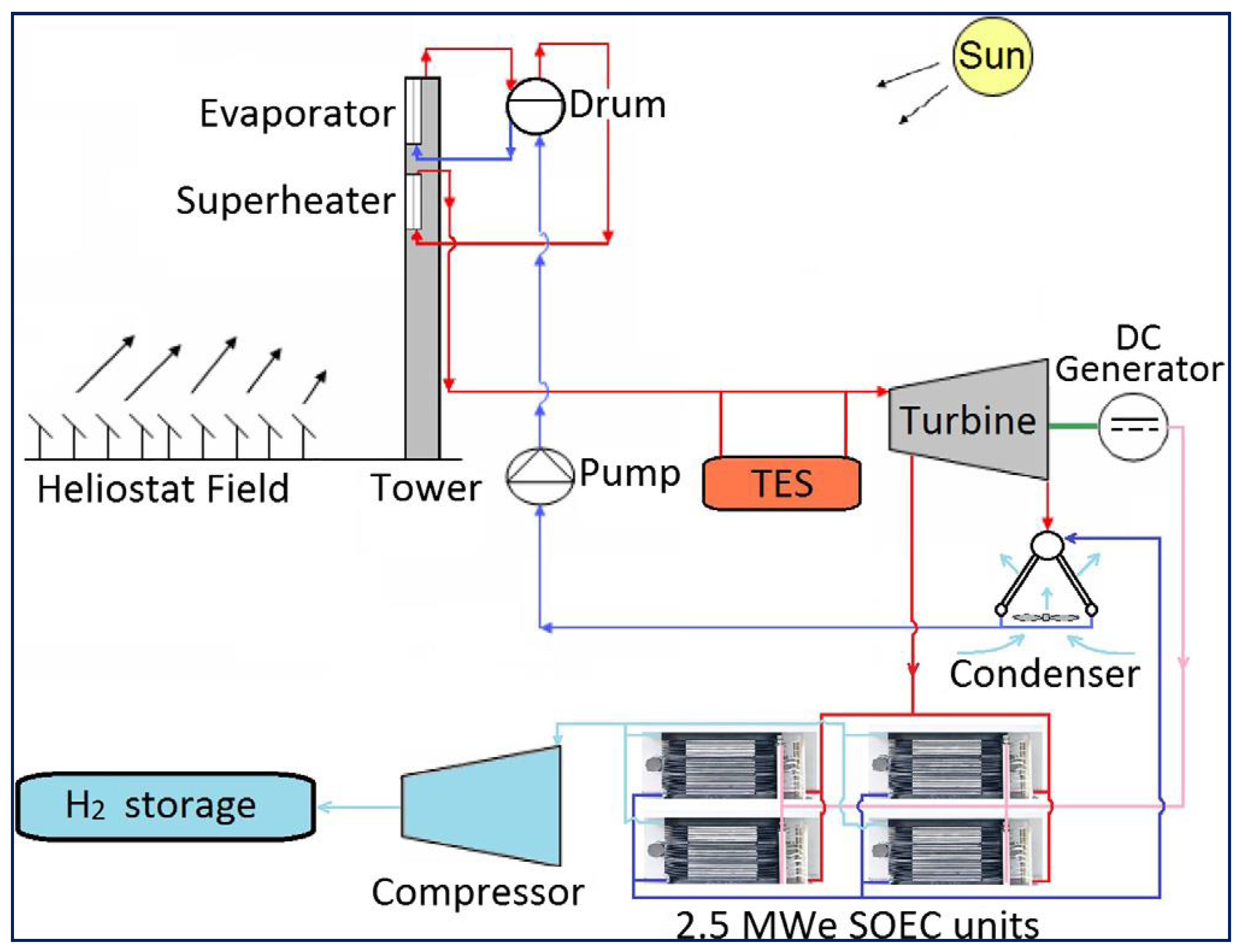
4.4. Solar Plant Design

A hybrid plant that combines a solar tower and hydrogen production, using a 646-heliostat field facing north. The heliostat is responsible for directing and concentrating solar energy towards the solar receiver located on the tower. The superheater and evaporator are two absorbers that are vertically aligned in the receiver, and a drum-style boiler is positioned above the superheater. Steam is at 70 bar and 550 °C at the entry of the turbine [78].
A solar multiple of 1.3 was used in the design of the CSP plant. Since there is a wealth of data available, the commercial CSP plants often use the Siemens steam turbine, specifically the model SST-700, as part of their power block. Because of the limited capacity of the plant, it is necessary to use a single-case non-reheated turbine. Three steam extractions provide three feed water heaters with steam (FWH). A dry cooling condenser was used since high-insolation regions lacked access to water. The electrolyzer for solar steam affects the amount of steam that can be used by the power block, which lowers the capacity and efficiency of the CSP plant [78].

4.5. Hybrid SOEC

Research was carried out to gain insights into SOECs based on mixed ionic conductors capable of simultaneously transporting both oxygen ions and protons, called hybrid SOECs [50]. Electrolytes that have both hydrogen as well as oxygen ions on one side of the cell can generate two electrolysis products, hydrogen and oxygen, in hybrid SOECs. Water electrolysis occurred at the two electrodes of hybrid SOECs, where this electrolyte was first introduced. Consequently, by enabling the simultaneous operation of the oxygen-SOEC and proton-SOEC in the hybrid SOEC system, additional hydrogen may be produced. The system achieved maximum efficiency using an electrolyte with protonic and oxide ion defects. At 750 °C, 10% humidified hydrogen, it showed a current density of 3.16 A/cm² at 1.3 V. Furthermore, the hybrid SOEC system proved reliable for hydrogen generation with no performance decline after 60 h of continuous operation [50]. The oxygen, proton, and hybrid SOEC are described in Figure 3.
According to tests, a hybrid SOEC may operate with great stability for 60 h without showing any signs of degradation [50]. Additionally, the hybrid SOEC system also exhibited the most outstanding electrochemical performance of hydrogen generation among the published SOECs and other typical water electrolysis systems [37]. In light of this, hybrid SOECs are a novel and energy-efficient alternative for hydrogen production [83].
Clean and reliable energy can be produced through the use of hybrid SOECs) powered by solar-driven water electrolysis to produce green hydrogen [84]. Due to energy source constraints and environmental concerns, it is crucial to use high-efficiency energy conversion techniques and non-polluting fuels [85]. A solution to energy and environmental issues lies in solid oxide electrolyzers or fuel cells, which directly convert chemical energy to electrical energy. Future stationary and mobile applications can benefit greatly from the advantages of fuel cells, including high efficiency, low pollution, the ability to use multiple fuels, and noise-free operation [86,87].

4.6. System Explanation

In a study, a standalone solar-hydrogen power plant was investigated. As described in Figure 4, it was made up of a 10 MWe solar power plant for direct steam generation and four 2.5 MWe SOEC units [88]. The DSG-CRS is solely responsible for providing the heat and electricity needed for electrolysis. The power supply takes care of the electric needs of the SOEC stack as well as the parasitic needs of the other plant equipment, including the electric super-heaters, pumps, blowers, and compressors. Due to potential variances in water quality, the feed water for the electrolyzer is kept separate from the solar plant water/steam line for heating purposes [78].
Several solar power plants supply feed water or steam to the electrolyzer, which is then returned as liquid water to the Rankine cycle for evaporation [89]. The hydrogen produced by the SOEC units is compressed and stored using a single system shared by all four electrolysis units [90].
The investigation was conducted using EBSILON®Professional, a feature of commercial software created to model thermodynamic processes, notably for the optimization of power plants [91]. Under steady-state settings, calculations were carried out at the design point, which, in terms of solar system analysis, corresponds to March 24 at 12 h solar time (spring equinox) [92]. The ambient temperature was supposed to be 25, and the relative humidity was assumed to be 60%. Near Seville, Spain, is where the hybrid plant is intended to be planted [93].

4.7. Hybrid Plant Scenarios

Several integration methods were developed to enhance the collaboration between the two subsystems. Lessening penalties for the DSG-CRS plant operating the SOEC at low pressure was the main objective of the initial designs. These concentrate on three things:
  • Identify the most efficient location for steam extraction in the solar plant.
  • Develop a method for utilizing the rejected hot streams from electrolysis to preheat the feed water for the CSP plant.
  • Determine the optimal point for re-injecting the condensed steam into the Rankine cycle.
  • Following that, a few concepts for the electrolysis process optimization were examined. These were concentrated on pressurizing the SOEC units to reduce parasitic losses brought on by the compression process [78].

4.7.1. Low-Pressure Circumstances

The layout of the model hybrid plant was built on the integration tactics recommended for nuclear power plants. The solar receiver immediately collects process steam (PS), which contains the highest energy level. This PS return was then reinjected into the power cycle condenser. To optimize the hybrid plant, new designs were developed and tested, resulting in the creation of the following scenarios.
  • Scenario 1: Low-pressure regulated steam was generated from the PS extraction received from the solar receiver. This steam can then be used to produce work through the high-pressure turbine stage. The aim is to reduce fines associated with CSP plants.
  • Scenario 2: The low-pressure feedwater heater (LP-FWH) re-injected the PS return, which reduces the heat requirement and increases the volume of steam expanded in the final stage of the turbine. Identifying different situations is a new area of study.
  • Scenario 3: As part of the strategy to decrease the need for LP-FWHs for heat and increase the capacity of our solar plant, we have installed a new FWH. This new FWH, called the heat recovery FWH (HR-FWH), was located between Pump 1 and the LP-FWH. It used rejected heat from the compressor inter-cooler system and exhaust sweep gas from the electrolysis process to preheat the feed water for the DSG-CRS plant.
  • Scenario 4: To enhance the efficiency of the SOEC unit, it is suggested to circulate hydrogen at a high temperature after the HRS-1. This method helps to lower the power demand of the cathode electric heater while maintaining a high temperature after hydrogen recirculation to maximize the productivity of HRS-1.
  • Scenario 5: In order to simplify the heat recovery system for the electrolyzer, the exhaust sweep gas stream was utilized to feed the economizer of the cathode loop instead of the exhaust cathode stream. This allows for a more centralized and compact heat recovery system for the preheating system of the solar plant by situating the condenser of the cathode loop near the compressor input.

4.7.2. High-Pressure Scenarios

The hydrogen compressor is the Balance of the Plant (BoP) component with the highest power requirements. Therefore, in order to increase the effectiveness of the electrolysis unit, the possible advantages of running the stack at high pressure were investigated. The maximum working pressure for the stack is 25 bar. This is because a certain temperature difference is required for evaporation, and the pressure decreases as it moves through the pipes and heat exchangers. Additionally, the SST-700 solar turbine was used, which has a maximum controllable PS extraction pressure of 40 bar. The SOEC unit experiences added pressure losses that reduce the hydrogen storage pressure to 22 bar, which is the designated gas supply pressure for all situations. This rise in pressure within the SOEC unit affects both the DSG-CRS plant and the electrolyzer [78].
In high-pressure situations, the exhaust gas from HRS-1 is too hot for conventional blowers to handle. As a solution, scenario 3 was used as the default. Additionally, since hydrogen can be stored directly, the need for a hydrogen compressor was eliminated. This change should reduce parasitic utilization even if the sweep gas stream needs pressurization. Despite recommendations from multiple authors to eliminate the sweep gas, it was kept due to safety concerns. To meet API standard 618 [94], the sweep gas was compressed using an intercooler compressor with multiple stages until it reached a pressure of 26. To maintain a discharge temperature of 194 °C after the HRS-2 heats the compressed sweep gas, only two intermediate intercoolers were incorporated in the design of the compressor instead of the recommended three-stage compressor [78].

4.7.3. Overall Hybrid Plant Performance

The efficiency of the hybrid plant can be improved by 3.8% to 4.7%, depending on the location of the PS extraction and PS return re-injection in the solar plant. One way to enhance the situation is by cycling hydrogen in the electrolysis system at a high temperature and utilizing the rejected hot streams from the electrolyzer to warm the water for the solar tower.
One way to decrease penalties for the CSP plant is to use low-pressure steam from the solar plant and recycle the hot stream from the electrolyzer to warm the feed water for the Rankine cycle. This could potentially reduce penalties by 60%. On the other hand, water or steam can be used as a sweep gas for electrolysis, cutting compression effort by half or eliminating it. Based on the findings, it appears that incorporating a PSA system into a high-pressure solid oxide electrolysis unit would be the best design for a hydrogen production facility. This integration could increase the efficiency of the hybrid plant by 5.8% and also result in the generation of oxygen as a byproduct.

5. New Method for SOEC-Based Hydrogen Production

Storing solar energy can be achieved by generating hydrogen using high-temperature electrolysis cells with solar photovoltaic cells [76,95]. Researchers have investigated a new system for generating hydrogen that includes a solid oxide electrolysis cell, a photovoltaic cell, and a photon-enhanced thermionic emission cell (PETE) [76]. The SOEC can generate steam at high temperatures between 800° and 1000 °C by utilizing waste heat recovery from the PV cell and PETE module [6].
By utilizing high-temperature electrolysis, it is possible to decrease the amount of energy required to separate water. While this process may lead to an increase in heat production, it can also decrease the amount of Gibbs free energy required to split water [96]. High-temperature electrolysis decreases the energy requirement to separate water. Recovering waste heat can enhance the efficiency of PV cells at low temps and increase hydrogen production [97].
The potentiality of the system for first law thermodynamic efficiency (FLTE), solar energy efficiency (SEA), and solar-to-hydrogen (STH) efficiency are all significant, with predicted values of 77.05%, 55.99%, and 29.61%, respectively. These findings establish a theoretical foundation for investigating and implementing effective and feasible solar hydrogen production methods [6].

5.1. Solar Hydrogen Generation System Integrating PV/PETE and SOEC

High-temperature water electrolysis using solid oxide electrolysis cells (SOEC) is preferable to low-temperature proton exchange membrane (PEM) and alkaline electrolysis. This is because it uses more chemical reaction energy, has a faster rate of chemical reaction, and does not require precious metals as electrode catalysts [98].
To assess and enhance the thermodynamic efficiency of this system, a theoretical model was developed. The system recovers excess heat from the PV cell module by using a combination of PV cells and PETE to raise the temperature of water from room temperature to the electrolysis temperature (600–1000 °C). The PV cell is utilized when the water or steam flow is below 250 °C, while the PETE generates energy and heats the steam in the other part [6].
The SOEC module generates hydrogen through the use of high-temperature steam and power [99]. Rather than using a low-temperature electrolysis module that may reduce power consumption but requires more thermal energy (at a relatively low energy level), a high-temperature electrolysis module is used [100]. Initially, thermodynamic models were created for high-temperature electrolysis modules, as well as PV cells or PETE modules [101,102].

5.2. Model and Performances

The experiment for the heating system model determined the efficiency of the total power generating module, concentration ratio, and temperature. These factors were based on the absorbed energy, which would later be converted into output electrical energy in the solar system [103]. The energy analysis schematic diagram for the heating system is illustrated in Figure 5.
Several factors, such as the thickness of the electrolyte, the symmetry factor or charge transfer, the coefficient, the number of electrons produced per reaction, the thickness of the anode and cathode, their activation energies, and the exchange current density, were calculated [104]. The computed data for these factors, along with the heating settings and the electrolysis section model, are described in Table 2. The table is represented on the basis of acquiring the calculations of the data, the results of the heating parameters and the electrolysis section model [6].
The flow channel beneath the PETE and PV modules measures 0.1 m and 0.001 m in height, respectively. Since the PV and PETE modules are covered by the flow channel, they have the same surface area for capturing solar energy. Altering the width at a fixed length or the length at a fixed width would yield the same results in terms of generating electrical and heat energy for both modules. Additionally, the impact of tube length on water temperature and solar energy efficiency was investigated.
As the tube length increases from 0 to 5 m, the temperatures of the PV cell, PETE module, and water also increase. If the intensity of I is 1000 W/m2, the highest steam temperature would be 970.5 °C. However, the efficiency of the PV cell decreases with rising temperature before stabilizing, causing the solar-to-electricity efficiency to drop initially at a fixed flow rate. Additionally, solar conversion efficiency decreases rapidly due to the low specific heat capacity of steam, causing the temperature to increase quickly after evaporation. While transitioning from the PV cell to PETE, the solar-to-electricity efficiency decreases sharply but then begins to rise again with the trend of PETE efficiency (ηTi,pv) at around ~33.49%. There may be an upper-efficiency limit achieved at around this point [1].

5.3. Efficiency of The System

By analyzing various system features, the estimated efficiency of the system was determined. This analysis included examining the first law of thermodynamic efficiency, exergy efficiency, STH efficiency, solar-to-electricity efficiency, and electrolysis efficiency. The exergy STH efficiency had the highest value at 77.05%, followed by the first law thermodynamic efficiency at 55.99% and 29.61% [6]. Based on the results of the study, it was discovered that the overpotential of the SOEC electrolyzer is quite high during electrolysis at low temperatures, which leads to a decrease in STH efficiency. However, increasing the flow rate of water can result in a boost in first law thermodynamic efficiency. This system exhibits great potential as a solar energy conversion and storage tool that can be utilized in the civil sector. In addition to generating electricity, it can also produce thermal energy and hydrogen [100].

6. Comparing and Contrasting Analysis Methods

The CSP hybrid hydrogen plant is a solar power plant that produces hydrogen on its own. By integrating a PSA system with a high-pressure solid oxide electrolysis unit, it was shown that this design is the most efficient, increasing the efficiency of the hybrid plant by 5.8%. Additionally, oxygen is produced as a byproduct [4].
Although the DSG-CRS plant is currently linked to the power network and the hybrid plant is designed for grid balancing, the priority should be increasing the capacity of the solar power plant. The best solution is to choose scenario 5, which involves using the electrolyzer at low pressure and redirecting its exhaust heat to heat the feed water for the solar plant [4].
It appears that the PV cell module has a high solar-to-hydrogen efficiency, potentially reaching 77.05%. This makes it a practical and effective option for generating solar hydrogen [6]. The thermodynamic efficiencies of the PV plant remain high during sunlight and are more cost-effective than a hybrid CSP plant. However, energy efficiency decreases as solar thermal energy loss increases and temperature rises with high irradiation intensity. There is ongoing work to integrate the cell module and achieve even higher optimal efficiencies.

7. Cost Evaluation for SOEC

Experts predict that solid oxide electrolyzers will soon become the third-largest technology in water electrolysis, surpassing alkaline and acid polymer hydrogen-generating technologies [105]. Despite still being in the research and development phase, this technology is not new and has been attracting attention since the late 1960s. By utilizing high working temperatures of up to 800–1000 °C, this technology has the potential to significantly increase the efficiency of water electrolysis [106]. Solid oxide installations operate similarly to steam electrolyzers because they use high temperatures to split water into hydrogen and oxygen [107].
It is expected that the greatest reduction in costs will come from the balance of plant, power electronics, and gas conditioning with the overall increase in the size of hydrogen plants, not just the stack size [108]. This is because there are limitations in physical and technical capabilities for larger stack sizes. For instance, larger stacks may experience more leaks and mechanical instability problems, while increasing the surface area of the cell may not be feasible with current technological advancements [41]. Therefore, the remaining cost components are likely to have a greater impact from economies of scale due to their simpler technological complexity.
An example of a cost increase in compressors is that their price only goes up by four times for every tenfold increase in size. This means that when there is an increase in capacity, the increase in stack size would contribute more to the overall cost than the increase in compressor size [109]. As a result, when scaling up the module size, the stack component is likely to have a bigger impact on the overall cost compared to other components. SOECs are not yet fully commercialized and are currently more expensive compared to alkaline or PEM technologies, making it difficult for them to compete in the market [110].
By 2030, it is expected that the cost of solid oxide systems will significantly decrease, with values as low as EUR 750/kWel with industrial scale-up [38]. However, due to their pre-commercial condition, capital costs for SOEL still vary greatly and are unclear. Nevertheless, it is undeniable that these costs are above EUR 3000/kWel [38].
Table 3 provides a summary comparison of all processes of water electrolysis thus far, including operational and financial features of each technology spanning from system specifics to some purely decorative features.
According to Table 3, solid oxide electrolysis costs more due to its capital cost, together with the maintenance cost, which is estimated to be around EUR 2000 per kilowatt hour, equivalent to USD 1933.02 per kilowatt hour. In contrast, it is more expensive than other types of electrolysis but considering the efficiency, it is higher and uses low energy consumption to operate.

8. Commercialization and Market Review

It seems that there are only a few participants in the SOEC area, but they are making big bets on its potential. This is not surprising, as the technology is getting closer to being commercialized, and green hydrogen is likely to become one of the main fuels. The limited commercialization of SOEC in portable and emergency power applications can be attributed to its significant heat generation, increased weight, and increased need for appropriate thermal shielding. Nowadays, industries are devoting resources to research and development in order to tackle such technological issues associated with SOEC. The global commercialization processes for SOEC are explained in Figure 6.
Many governments and organizations in countries like Germany and Denmark have made significant declarations indicating the adoption of net-zero objectives for energy-related carbon dioxide emissions, which has raised awareness of the need for hydrogen. [123,124]. Germany has announced that it will prioritize green hydrogen in its national hydrogen strategy. This decision reflects the goal of the country to achieve self-sufficiency in green energy production, as well as its desire to play a leading role in the global energy revolution [125]. As part of this strategy, Germany has already unveiled its PtL plan for aviation fuels. Other regions and economies have also demonstrated similar initiatives [126].
Although SOECs are expected to become fully commercially viable, their development will continue for some time. Further research into the electrolysis processes will yield better performance and longer-lasting benefits, while still meeting cost requirements [127]. For instance, Topsoe plans to build a manufacturing facility that produces highly efficient solid oxide electrolyzers (SOECs) with an initial capacity of 500 megawatts per year and the potential to expand to 5 gigawatts per year. Additionally, waste heat generated from current processes, such as methanol and ammonia synthesis, can be utilized to reduce the cost of SOEC electrolysis [128]. Topsoe patented SOEC electrolyzers that have efficiencies exceeding 90% when electrolyzing water into hydrogen, outperforming current conventional alkaline or PEM electrolyzers. The facility is expected to be operational by 2023.
Electricity costs are the largest factor influencing the cost of hydrogen production via electrolysis, and efficiency plays an important role in reducing costs. US-based Bloom Energy claims to have erected the biggest solid oxide electrolyzer (SOE) in the world at a NASA research center in California. The 4 MW machine will create 20-25% more hydrogen per megawatt than any commercially proved alkaline or PEM counterpart, according to Bloom Energy [129].

9. Conclusions and Recommendations

Hydrogen is considered one of the most promising energy carriers that can be used to generate electricity from renewable energy, concentrating the use of solar energy. By varying the technologies currently practiced, green hydrogen can be produced using the electrolysis of water with electricity generated using renewable energy. Taking into account the rise of global warming, volatile oil prices, and fossil fuel depletion issues, the production of hydrogen has received considerable interest through electrolysis as a new stable energy generation in the future. Subsequently, building electrolyzers to produce hydrogen from solar and wind energy offers a clean and affordable option, even when taking into account the cost of delivering hydrogen to consumers or end users. The study aims to explore various solar energy storage and conversion systems that can be effectively used for civil purposes. The review leads to the primary findings that may be drawn:
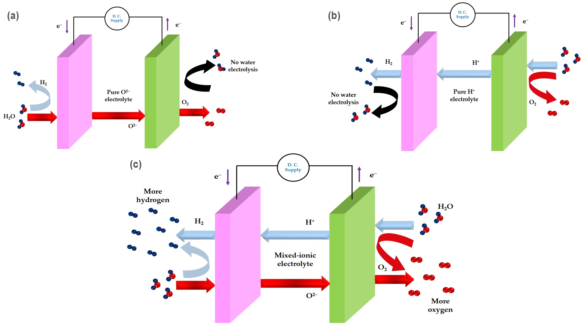
  • Though hydrogen is an excellent fuel source that is clean and abundant, there are still a number of issues standing in the way of its mainstreaming despite the promising characteristics of SOECs; there is still a need to undertake further research into reducing degradation, and the successful designs for SOECs must be scaled up if they are to become an industry electrolyzer. Solid-state electrolyzers may pull energy from the heat they generate as they run at higher temperatures, but there is still an opportunity for advancement in SOECs. Oxygen SEOCs permit oxygen ions to pass through, and hydrogen SOECs only permit hydrogen ions to pass through. Nevertheless, the amount of hydrogen that can be produced was reduced in a single way. However, hybrid SOECs employ a mixed-ion conductor to simultaneously carry positively charged hydrogen ions (protons) and negatively charged oxygen ions.
  • A viable method of storing solar energy and extracting hydrogen is the combination of solar photovoltaic (PV) cells with high-temperature electrolysis cells. The solar energy efficiency and solar-to-hydrogen efficiency (STH efficiency) might be as high as 77.05%, 55.99%, and 29.61%, respectively. These figures are anticipated to offer a theoretical foundation for the study and practical implementation of solar hydrogen generation. On the other hand, the atmospheric conditions that impact PV cell performance and STH production and storage are the challenges that stand in the way of solar hydrogen generation since solar energy fluctuates according to the season. However, there are fewer studies on the development of PV cells and PETE modules associated with the SOEC, and this deserves further research.
  • The cost of producing hydrogen using SOECs now comes to about EUR 2000 per kilowatt-hour or USD 1933.02 per hour in USD. Further study is required to determine if the components in the SOEC will withstand long-term, high-temperature operation, even though it has better efficiency and low energy usage. The cost is still higher than other electrolysis, and further research is needed to reduce the overall system cost. Furthermore, to support the commercial use of hybrid SOECs, future research should concentrate on large-scale manufacturing technology and process simplification.

Author Contributions

Conceptualization, S.A., M.S.R. and A.K.A.; writing—original draft preparation, S.A., A.N.S.B.S., M.S.R., A.K. and M.R.U.; writing—review and editing, K.Z.B., M.R.U., A.K., L.T., Z.B.I., K.A.K. and A.K.A.; supervision, K.A.K., K.Z.B., Z.B.I., L.T. and A.K.A.; funding acquisition, K.A.K. and K.Z.B. All authors have read and agreed to the published version of the manuscript.

Funding

The work was completed as part of Project No. AP09261208 under the Ministry of Science and Higher Education, Kazakhstan.

Data Availability Statement

Not applicable.

Acknowledgments

The authors highly acknowledge the Universiti Brunei Darussalam and L.N. Gumilyov Eurasian National University for facilitating this work.

Conflicts of Interest

The authors declare no conflict of interest.

References

  1. Stern, N.; Valero, A. Innovation, Growth and the Transition to Net-Zero Emissions. Res. Policy 2021, 50, 104293. [Google Scholar] [CrossRef] [PubMed]
  2. Holechek, J.L.; Geli, H.M.E.; Sawalhah, M.N.; Valdez, R. A Global Assessment: Can Renewable Energy Replace Fossil Fuels by 2050? Sustainability 2022, 14, 4792. [Google Scholar] [CrossRef]
  3. Baquero, J.E.G.; Monsalve, D.B. A Proposal for the Transformation of Fossil Fuel Energy Economies to Hydrogen Economies through Social Entrepreneurship. In Entrepreneurial Innovation for Securing Long-Term Growth in a Short-Term Economy; IGI Global: Hershey, PA, USA, 2021; pp. 48–70. [Google Scholar] [CrossRef]
  4. Reza, M.S.; Afroze, S.; Kuterbekov, K.; Kabyshev, A.; Bekmyrza, K.Z.; Haque, M.N.; Islam, S.N.; Hossain, M.A.; Hassan, M.; Roy, H.; et al. Advanced Applications of Carbonaceous Materials in Sustainable Water Treatment, Energy Storage, and CO2 Capture: A Comprehensive Review. Sustainability 2023, 15, 8815. [Google Scholar] [CrossRef]
  5. Reza, M.S.; Ahmad, N.B.H.; Afroze, S.; Taweekun, J.; Sharifpur, M.; Azad, A.K. Hydrogen Production from Water Splitting through Photocatalytic Activity of Carbon-Based Materials. Chem. Eng. Technol. 2023, 46, 420–434. [Google Scholar] [CrossRef]
  6. Wang, H.; Kong, H.; Pu, Z.; Li, Y.; Hu, X. Feasibility of High Efficient Solar Hydrogen Generation System Integrating Photovoltaic Cell/photon-Enhanced Thermionic Emission and High-Temperature Electrolysis Cell. Energy Convers. Manag. 2020, 210, 112699. [Google Scholar] [CrossRef]
  7. International Energy Agency. Net Zero by 2050: A Roadmap for the Global Energy Sector; IEA: Paris, France, 2021. [Google Scholar]
  8. Zaiter, I.; Ramadan, M.; Bouabid, A.; El-Fadel, M.; Mezher, T. Potential Utilization of Hydrogen in the UAE’s Industrial Sector. Energy 2023, 280, 128108. [Google Scholar] [CrossRef]
  9. Jayaprabakar, J.; Sri Hari, N.S.; Badreenath, M.; Anish, M.; Joy, N.; Prabhu, A.; Rajasimman, M.; Kumar, J.A. Nano Materials for Green Hydrogen Production: Technical Insights on Nano Material Selection, Properties, Production Routes and Commercial Applications. Int. J. Hydrogen Energy 2023, in press. [Google Scholar] [CrossRef]
  10. Hassan, Q.; Abdulateef, A.M.; Hafedh, S.A.; Al-samari, A.; Abdulateef, J.; Sameen, A.Z.; Salman, H.M.; Al-Jiboory, A.K.; Wieteska, S.; Jaszczur, M. Renewable Energy-to-Green Hydrogen: A Review of Main Resources Routes, Processes and Evaluation. Int. J. Hydrogen Energy 2023, 48, 17383–17408. [Google Scholar] [CrossRef]
  11. AbouSeada, N.; Hatem, T.M. Climate Action: Prospects of Green Hydrogen in Africa. Energy Rep. 2022, 8, 3873–3890. [Google Scholar] [CrossRef]
  12. Yilanci, A.; Dincer, I.; Ozturk, H.K. A Review on Solar-Hydrogen/fuel Cell Hybrid Energy Systems for Stationary Applications. Prog. Energy Combust. Sci. 2009, 35, 231–244. [Google Scholar] [CrossRef]
  13. Espegren, K.; Damman, S.; Pisciella, P.; Graabak, I.; Tomasgard, A. The Role of Hydrogen in the Transition from a Petroleum Economy to a Low-Carbon Society. Int. J. Hydrogen Energy 2021, 46, 23125–23138. [Google Scholar] [CrossRef]
  14. Anika, O.C.; Nnabuife, S.G.; Bello, A.; Okoroafor, E.R.; Kuang, B.; Villa, R. Prospects of Low and Zero-Carbon Renewable Fuels in 1.5-Degree Net Zero Emission Actualisation by 2050: A Critical Review. Carbon Capture Sci. Technol. 2022, 5, 100072. [Google Scholar] [CrossRef]
  15. Hwang, H.T.; Varma, A. Hydrogen Storage for Fuel Cell Vehicles. Curr. Opin. Chem. Eng. 2014, 5, 42–48. [Google Scholar] [CrossRef]
  16. Møller, K.T.; Jensen, T.R.; Akiba, E.; Li, H.-W. Hydrogen-A Sustainable Energy Carrier. Prog. Nat. Sci. Mater. Int. 2017, 27, 34–40. [Google Scholar] [CrossRef]
  17. Karimi, M.; Mehrpooya, M.; Pourfayaz, F. Proposal and Investigation of a Novel Hybrid Hydrogen Production and Liquefaction Process Using Solid Oxide Electrolyzer, Solar Energy, and Thermoelectric Generator. J. Clean. Prod. 2022, 331, 130001. [Google Scholar] [CrossRef]
  18. Hassan, Q.; Sameen, A.Z.; Salman, H.M.; Jaszczur, M. Large-Scale Green Hydrogen Production via Alkaline Water Electrolysis Using Solar and Wind Energy. Int. J. Hydrogen Energy 2023, 48, 34299–34315. [Google Scholar] [CrossRef]
  19. Tashie-Lewis, B.C.; Nnabuife, S.G. Hydrogen Production, Distribution, Storage and Power Conversion in a Hydrogen Economy-A Technology Review. Chem. Eng. J. Adv. 2021, 8, 100172. [Google Scholar] [CrossRef]
  20. Martínez de León, C.; Ríos, C.; Brey, J.J. Cost of Green Hydrogen: Limitations of Production from a Stand-Alone Photovoltaic System. Int. J. Hydrogen Energy 2023, 48, 11885–11898. [Google Scholar] [CrossRef]
  21. Pathak, S.K.; Tyagi, V.V.; Chopra, K.; Kalidasan, B.; Pandey, A.K.; Goel, V.; Saxena, A.; Ma, Z. Energy, Exergy, Economic and Environmental Analyses of Solar Air Heating Systems with and without Thermal Energy Storage for Sustainable Development: A Systematic Review. J. Energy Storage 2023, 59, 106521. [Google Scholar] [CrossRef]
  22. Li, X.; Pan, L.; Zhang, J. Development Status Evaluation and Path Analysis of Regional Clean Energy Power Generation in China. Energy Strateg. Rev. 2023, 49, 101139. [Google Scholar] [CrossRef]
  23. Sharma, S.; Jain, K.K.; Sharma, A. Solar Cells: In Research and Applications—A Review. Mater. Sci. Appl. 2015, 6, 1145–1155. [Google Scholar] [CrossRef]
  24. Keiner, D.; Salcedo-Puerto, O.; Immonen, E.; van Sark, W.G.J.H.M.; Nizam, Y.; Shadiya, F.; Duval, J.; Delahaye, T.; Gulagi, A.; Breyer, C. Powering an Island Energy System by Offshore Floating Technologies towards 100% Renewables: A Case for the Maldives. Appl. Energy 2022, 308, 118360. [Google Scholar] [CrossRef]
  25. Irish Energy Company EI-H2 Is Planning to Build a Green Hydrogen Facility in Cork. Available online: https://fuelcellsworks.com/news/irish-energy-company-ei-h2-is-planning-to-build-a-green-hydrogen-facility-in-cork/ (accessed on 21 August 2023).
  26. Zenith Energy and Ei-H2 Announce Joint Venture for Green Energy Facility at Bantry Bay. Available online: https://fuelcellsworks.com/news/zenith-energy-and-ei-h2-announce-joint-venture-for-green-energy-facility-at-bantry-bay/ (accessed on 21 August 2023).
  27. Bauer, F.; Tilsted, J.P.; Pfister, S.; Oberschelp, C.; Kulionis, V. Mapping GHG Emissions and Prospects for Renewable Energy in the Chemical Industry. Curr. Opin. Chem. Eng. 2023, 39, 100881. [Google Scholar] [CrossRef]
  28. Arsad, A.Z.; Hannan, M.A.; Al-Shetwi, A.Q.; Hossain, M.J.; Begum, R.A.; Ker, P.J.; Salehi, F.; Muttaqi, K.M. Hydrogen Electrolyser for Sustainable Energy Production: A Bibliometric Analysis and Future Directions. Int. J. Hydrogen Energy 2023, 48, 4960–4983. [Google Scholar] [CrossRef]
  29. El-Emam, R.S.; Zamfirescu, C.; Gabriel, K.S. Hydrogen Production Pathways for Generation-IV Reactors. In Handbook of Generation IV Nuclear Reactors: A Guidebook; Woodhead Publishing: Sawston, UK, 2023; pp. 665–680. ISBN 9780128205884. [Google Scholar]
  30. Naimi, Y.; Antar, A. Hydrogen Generation by Water Electrolysis. In Advances in Hydrogen Generation Technologies; IntechOpen: London, UK, 2018; ISBN 978-1-78923-535-7. [Google Scholar]
  31. Arcos, J.M.M.; Santos, D.M.F. The Hydrogen Color Spectrum: Techno-Economic Analysis of the Available Technologies for Hydrogen Production. Gases 2023, 3, 25–46. [Google Scholar] [CrossRef]
  32. Diab, J.; Fulcheri, L.; Hessel, V.; Rohani, V.; Frenklach, M. Why Turquoise Hydrogen Will Be a Game Changer for the Energy Transition. Int. J. Hydrogen Energy 2022, 47, 25831–25848. [Google Scholar] [CrossRef]
  33. Ajanovic, A.; Sayer, M.; Haas, R. The Economics and the Environmental Benignity of Different Colors of Hydrogen. Int. J. Hydrogen Energy 2022, 47, 24136–24154. [Google Scholar] [CrossRef]
  34. Difference between Grey Blue and Green Hydrogen|Compare the Difference between Similar Terms. Available online: https://www.differencebetween.com/difference-between-grey-blue-and-green-hydrogen/ (accessed on 20 October 2023).
  35. Sajna, M.S.; Zavahir, S.; Popelka, A.; Kasak, P.; Al-Sharshani, A.; Onwusogh, U.; Wang, M.; Park, H.; Han, D.S. Electrochemical System Design for CO2 Conversion: A Comprehensive Review. J. Environ. Chem. Eng. 2023, 11, 110467. [Google Scholar] [CrossRef]
  36. Dincer, I.; AlZahrani, A.A. Electrolyzers. In Comprehensive Energy Systems; Elsevier: Amsterdam, The Netherlands, 2018; Volume 4–5, pp. 985–1025. ISBN 9780128095973. [Google Scholar]
  37. Nasser, M.; Megahed, T.F.; Ookawara, S.; Hassan, H. A Review of Water Electrolysis–based Systems for Hydrogen Production Using Hybrid/solar/wind Energy Systems. Environ. Sci. Pollut. Res. 2022, 29, 86994–87018. [Google Scholar] [CrossRef]
  38. Vidas, L.; Castro, R. Recent Developments on Hydrogen Production Technologies: State-of-the-Art Review with a Focus on Green-Electrolysis. Appl. Sci. 2021, 11, 11363. [Google Scholar] [CrossRef]
  39. Sapountzi, F.M.; Gracia, J.M.; Fredriksson, H.O.; Niemantsverdriet, J.H. Electrocatalysts for the Generation of Hydrogen, Oxygen and Synthesis Gas. Prog. Energy Combust. Sci. 2017, 58, 1–35. [Google Scholar] [CrossRef]
  40. Lo Basso, G.; Mojtahed, A.; Pastore, L.M.; De Santoli, L. High-Temperature Green Hydrogen Production: A Innovative—Application of SOEC Coupled with AEC through sCO2 HP. Int. J. Hydrogen Energy 2023, in press. [Google Scholar] [CrossRef]
  41. Subotić, V.; Hochenauer, C. Analysis of Solid Oxide Fuel and Electrolysis Cells Operated in a Real-System Environment: State-of-the-Health Diagnostic, Failure Modes, Degradation Mitigation and Performance Regeneration. Prog. Energy Combust. Sci. 2022, 93, 101011. [Google Scholar] [CrossRef]
  42. Zhang, X.; Jin, Y.; Li, D.; Xiong, Y. A Review on Recent Advances in Micro-Tubular Solid Oxide Fuel Cells. J. Power Source 2021, 506, 230135. [Google Scholar] [CrossRef]
  43. Afroze, S.; Reza, M.S.; Amin, M.R.; Taweekun, J.; Azad, A.K. Progress in Nanomaterials Fabrication and Their Prospects in Artificial Intelligence towards Solid Oxide Fuel Cells: A Review. Int. J. Hydrogen Energy 2022, in press. [Google Scholar] [CrossRef]
  44. Afroze, S.; Reza, M.S.; Cheok, Q.; Islam, S.N.; Abdalla, A.M.; Taweekun, J.; Azad, A.K.; Khalilpoor, N.; Issakhov, A. Advanced Applications of Fuel Cells during the COVID-19 Pandemic. Int. J. Chem. Eng. 2021, 2021, 5539048. [Google Scholar] [CrossRef]
  45. Afroze, S.; Absah, H.Q.H.H.; Reza, M.S.; Somalu, M.R.; Park, J.Y.; Nekoonam, S.; Issakhov, A.; Azad, A.K. Structural and Electrochemical Properties of Lanthanum Silicate Apatites La10Si6−X−0.2AlxZn0.2O27−δ for Solid Oxide Fuel Cells (SOFCs). Int. J. Chem. Eng. 2021, 2021, 6621373. [Google Scholar] [CrossRef]
  46. Wei, H.; Dai, J.; Maharik, I.; Ghasemi, A.; Mouldi, A.; Brahmia, A. Simultaneous Synthesis of H2, O2, and N2 via an Innovatory Energy System in Coronavirus Pandemic Time: Design, Techno-Economic Assessment, and Optimization Approaches. Int. J. Hydrogen Energy 2022, 47, 26038. [Google Scholar] [CrossRef]
  47. Benghanem, M.; Mellit, A.; Almohamadi, H.; Haddad, S.; Chettibi, N.; Alanazi, A.M.; Dasalla, D.; Alzahrani, A. Hydrogen Production Methods Based on Solar and Wind Energy: A Review. Energies 2023, 16, 757. [Google Scholar] [CrossRef]
  48. Jin, C.; Xiao, J.; Hou, J.; Wu, X.; Zhang, J.; Du, E. Flexibility Improvement Evaluation of Hydrogen Storage Based on Electricity–hydrogen Coupled Energy Model. Glob. Energy Interconnect. 2021, 4, 371–383. [Google Scholar] [CrossRef]
  49. Zhang, Q.; Chang, Z.; Fu, M.; Ren, T.; Li, X. Thermal and Electrochemical Performance Analysis of an Integrated Solar SOEC Reactor for Hydrogen Production. Appl. Therm. Eng. 2023, 229, 120603. [Google Scholar] [CrossRef]
  50. Kim, J.; Jun, A.; Gwon, O.; Yoo, S.; Liu, M.; Shin, J.; Lim, T.H.; Kim, G. Hybrid-Solid Oxide Electrolysis Cell: A New Strategy for Efficient Hydrogen Production. Nano Energy 2018, 44, 121–126. [Google Scholar] [CrossRef]
  51. Nasser, M.; Hassan, H. Assessment of Hydrogen Production from Waste Heat Using Hybrid Systems of Rankine Cycle with Proton Exchange Membrane/solid Oxide Electrolyzer. Int. J. Hydrogen Energy 2023, 48, 7135–7153. [Google Scholar] [CrossRef]
  52. El-Emam, R.S.; Ozcan, H.; Dincer, I. Comparative Cost Evaluation of Nuclear Hydrogen Production Methods with the Hydrogen Economy Evaluation Program (HEEP). Int. J. Hydrogen Energy 2014, 40, 11168–11177. [Google Scholar] [CrossRef]
  53. Jolaoso, L.A.; Bello, I.T.; Ojelade, O.A.; Yousuf, A.; Duan, C.; Kazempoor, P. Operational and Scaling-up Barriers of SOEC and Mitigation Strategies to Boost H2 Production- a Comprehensive Review. Int. J. Hydrogen Energy 2023, 48, 33017–33041. [Google Scholar] [CrossRef]
  54. Wang, F.; Wang, L.; Ou, Y.; Lei, X.; Yuan, J.; Liu, X.; Zhu, Y. Thermodynamic Analysis of Solid Oxide Electrolyzer Integration with Engine Waste Heat Recovery for Hydrogen Production. Case Stud. Therm. Eng. 2021, 27, 101240. [Google Scholar] [CrossRef]
  55. Ni, M.; Leung, M.K.H.; Leung, D.Y.C. Technological Development of Hydrogen Production by Solid Oxide Electrolyzer Cell (SOEC). Int. J. Hydrogen Energy 2008, 33, 2337–2354. [Google Scholar] [CrossRef]
  56. Shen, M.; Ai, F.; Ma, H.; Xu, H.; Zhang, Y. Progress and Prospects of Reversible Solid Oxide Fuel Cell Materials. iScience 2021, 24, 103464. [Google Scholar] [CrossRef]
  57. Kojima, H.; Nagasawa, K.; Todoroki, N.; Ito, Y.; Matsui, T.; Nakajima, R. Influence of Renewable Energy Power Fluctuations on Water Electrolysis for Green Hydrogen Production. Int. J. Hydrogen Energy 2023, 48, 4572–4593. [Google Scholar] [CrossRef]
  58. Tucker, M.C. Progress in Metal-Supported Solid Oxide Electrolysis Cells: A Review. Int. J. Hydrogen Energy 2020, 45, 24203–24218. [Google Scholar] [CrossRef]
  59. Liang, J.; Han, M. Different Performance and Mechanisms of CO2 Electrolysis with CO and H2 as Protective Gases in Solid Oxide Electrolysis Cell. Int. J. Hydrogen Energy 2022, 47, 18606–18618. [Google Scholar] [CrossRef]
  60. Yan, Y.; Fang, Q.; Blum, L.; Lehnert, W. Performance and Degradation of an SOEC Stack with Different Cell Components. Electrochim. Acta 2017, 258, 1254–1261. [Google Scholar] [CrossRef]
  61. Xu, D.; Yan, A.; Yang, Y.; Xu, S.; Zhou, Y.; Yang, S.; Lin, W.F. Fast Ion-Conductive Electrolyte Based on a Doped LaAlO3 with an Amorphous Surface Layer for Low-Temperature Solid Oxide Fuel Cells. J. Power Source 2023, 561, 232723. [Google Scholar] [CrossRef]
  62. Kirchheim, R. On the Mixed Ionic and Electronic Conductivity in Polarized Yttria Stabilized Zirconia. Solid State Ion. 2018, 320, 239–258. [Google Scholar] [CrossRef]
  63. Gaikwad, P.S.; Mondal, K.; Shin, Y.K.; van Duin, A.C.T.; Pawar, G. Enhancing the Faradaic Efficiency of Solid Oxide Electrolysis Cells: Progress and Perspective. NPJ Comput. Mater. 2023, 9, 149. [Google Scholar] [CrossRef]
  64. Chen, Z.; Danilov, D.L.; Eichel, R.A.; Notten, P.H.L. Porous Electrode Modeling and Its Applications to Li-Ion Batteries. Adv. Energy Mater. 2022, 12, 2201506. [Google Scholar] [CrossRef]
  65. Li, X.; Shao, J.; Kim, S.K.; Yao, C.; Wang, J.; Miao, Y.R.; Zheng, Q.; Sun, P.; Zhang, R.; Braun, P.V. High Energy Flexible Supercapacitors Formed via Bottom-up Infilling of Gel Electrolytes into Thick Porous Electrodes. Nat. Commun. 2018, 9, 2578. [Google Scholar] [CrossRef]
  66. Rashidi, S.; Karimi, N.; Sunden, B.; Kim, K.C.; Olabi, A.G.; Mahian, O. Progress and Challenges on the Thermal Management of Electrochemical Energy Conversion and Storage Technologies: Fuel Cells, Electrolysers, and Supercapacitors. Prog. Energy Combust. Sci. 2022, 88, 100966. [Google Scholar] [CrossRef]
  67. Choi, Y.; Byun, S.; Seo, D.W.; Hwang, H.J.; Kim, T.W.; Kim, S.D. New Design and Performance Evaluation of 1 kW-Class Reversible Solid Oxide Electrolysis-Fuel Cell Stack Using Flat-Tubular Cells. J. Power Source 2022, 542, 231744. [Google Scholar] [CrossRef]
  68. Nechache, A.; Hody, S. Alternative and Innovative Solid Oxide Electrolysis Cell Materials: A Short Review. Renew. Sustain. Energy Rev. 2021, 149, 111322. [Google Scholar] [CrossRef]
  69. Wang, Y.; Li, W.W.; Ma, L.; Li, W.W.; Liu, X. Degradation of Solid Oxide Electrolysis Cells: Phenomena, Mechanisms, and Emerging Mitigation strategies—A Review. J. Mater. Sci. Technol. 2020, 55, 35–55. [Google Scholar] [CrossRef]
  70. Trini, M.; Hauch, A.; De Angelis, S.; Tong, X.; Hendriksen, P.V.; Chen, M. Comparison of Microstructural Evolution of Fuel Electrodes in Solid Oxide Fuel Cells and Electrolysis Cells. J. Power Source 2020, 450, 227599. [Google Scholar] [CrossRef]
  71. Deseure, J.; Aicart, J.; Deseure, J.; Aicart, J. Solid Oxide Steam Electrolyzer: Gas Diffusion Steers the Design of Electrodes. In Electrodialysis; IntechOpen: London, UK, 2019; ISBN 978-1-83968-383-1. [Google Scholar]
  72. Serhan, M.; Sprowls, M.; Jackemeyer, D.; Long, M.; Perez, I.D.; Maret, W.; Tao, N.; Forzani, E. Total Iron Measurement in Human Serum with a Smartphone. In Proceedings of the AIChE Annual Meeting, Orlando, FL, USA, 10–15 November 2019. [Google Scholar]
  73. Zarabi Golkhatmi, S.; Asghar, M.I.; Lund, P.D. A Review on Solid Oxide Fuel Cell Durability: Latest Progress, Mechanisms, and Study Tools. Renew. Sustain. Energy Rev. 2022, 161, 112339. [Google Scholar] [CrossRef]
  74. Elder, R.; Cumming, D.; Mogensen, M.B. High Temperature Electrolysis. In Carbon Dioxide Utilisation: Closing the Carbon Cycle, 1st ed.; Elsevier B.V.: Amsterdam, The Netherlands, 2015; pp. 183–209. ISBN 9780444627483. [Google Scholar]
  75. Joubi, A.; Akimoto, Y.; Okajima, K. A Production and Delivery Model of Hydrogen from Solar Thermal Energy in the United Arab Emirates. Energies 2022, 15, 4000. [Google Scholar] [CrossRef]
  76. Shafiei Kaleibari, S.; Yanping, Z.; Abanades, S. Solar-Driven High Temperature Hydrogen Production via Integrated Spectrally Split Concentrated Photovoltaics (SSCPV) and Solar Power Tower. Int. J. Hydrogen Energy 2019, 44, 2519–2532. [Google Scholar] [CrossRef]
  77. Haussener, S. Solar Fuel Processing: Comparative Mini-Review on Research, Technology Development, and Scaling. Sol. Energy 2022, 246, 294–300. [Google Scholar] [CrossRef]
  78. Sanz-Bermejo, J.; Muñoz-Antón, J.; Gonzalez-Aguilar, J.; Romero, M. Optimal Integration of a Solid-Oxide Electrolyser Cell into a Direct Steam Generation Solar Tower Plant for Zero-Emission Hydrogen Production. Appl. Energy 2014, 131, 238–247. [Google Scholar] [CrossRef]
  79. Biswas, S.; Kaur, G.; Paul, G.; Giddey, S. A Critical Review on Cathode Materials for Steam Electrolysis in Solid Oxide Electrolysis. Int. J. Hydrogen Energy 2023, 48, 12541–12570. [Google Scholar] [CrossRef]
  80. Singh Aulakh, D.J.; Boulama, K.G.; Pharoah, J.G. On the Reduction of Electric Energy Consumption in Electrolysis: A Thermodynamic Study. Int. J. Hydrogen Energy 2021, 46, 17084–17096. [Google Scholar] [CrossRef]
  81. Kupecki, J.; Mastropasqua, L.; Motylinski, K.; Ferrero, D. Multilevel Modeling of Solid Oxide Electrolysis. In Solid Oxide-Based Electrochemical Devices: Advances, Smart Materials and Future Energy Applications; INC: New York, NY, USA, 2020; pp. 123–166. ISBN 9780128182857. [Google Scholar]
  82. Pitz-Paal, R. Concentrating Solar Power. In Future Energy: Improved, Sustainable and Clean Options for Our Planet; Elsevier Ltd.: Amsterdam, The Netherlands, 2020; pp. 413–430. ISBN 9780081028865. [Google Scholar]
  83. Sarker, A.K.; Azad, A.K.; Rasul, M.G.; Doppalapudi, A.T. Prospect of Green Hydrogen Generation from Hybrid Renewable Energy Sources: A Review. Energies 2023, 16, 1556. [Google Scholar] [CrossRef]
  84. Zhang, S.; Zhang, N. Review on Integrated Green Hydrogen Polygeneration system——Electrolysers, Modelling, 4 E Analysis and Optimization. J. Clean. Prod. 2023, 414, 137631. [Google Scholar] [CrossRef]
  85. Maddaloni, M.; Marchionni, M.; Abbá, A.; Mascia, M.; Tola, V.; Carpanese, M.P.; Bertanza, G.; Artioli, N. Exploring the Viability of Utilizing Treated Wastewater as a Sustainable Water Resource for Green Hydrogen Generation Using Solid Oxide Electrolysis Cells (SOECs). Water 2023, 15, 2569. [Google Scholar] [CrossRef]
  86. Biswas, S.; Rathore, S.S.; Kulkarni, A.P.; Giddey, S.; Bhattacharya, S. A Theoretical Study on Reversible Solid Oxide Cells as Key Enablers of Cyclic Conversion between Electrical Energy and Fuel. Energies 2021, 14, 4517. [Google Scholar] [CrossRef]
  87. Omeiza, L.A.; Abdalla, A.M.; Wei, B.; Dhanasekaran, A.; Subramanian, Y.; Afroze, S.; Reza, M.S.; Bakar, S.A.; Azad, A.K. Nanostructured Electrocatalysts for Advanced Applications in Fuel Cells. Energies 2023, 16, 1876. [Google Scholar] [CrossRef]
  88. Saghafifar, M.; Mohammadi, K.; Powell, K. Design and Analysis of a Dual-Receiver Direct Steam Generator Solar Power Tower Plant with a Flexible Heliostat Field. Sustain. Energy Technol. Assess. 2020, 39, 100698. [Google Scholar] [CrossRef]
  89. Delgado-Torres, A.M.; García-Rodríguez, L. Solar Desalination Driven by Organic Rankine Cycles (Orc) and Supercritical CO2 Power Cycles: An Update. Processes 2022, 10, 153. [Google Scholar] [CrossRef]
  90. Jolaoso, L.A.; Duan, C.; Kazempoor, P. Life Cycle Analysis of a Hydrogen Production System Based on Solid Oxide Electrolysis Cells Integrated with Different Energy and Wastewater Sources. Int. J. Hydrogen Energy 2023, in press. [Google Scholar] [CrossRef]
  91. Lin, X.; Song, H.; Liu, Y. Process Design and Comprehensive Comparison of Coal- and Biomass-Fired Oxy-Combustion Power Plant. Chem. Eng. Res. Des. 2022, 186, 568–586. [Google Scholar] [CrossRef]
  92. Biencinto, M.; González, L.; Valenzuela, L. Using Time-Windowed Solar Radiation Profiles to Assess the Daily Uncertainty of Solar Thermal Electricity Production Forecasts. J. Clean. Prod. 2022, 379, 134821. [Google Scholar] [CrossRef]
  93. Sánchez Ramos, J.; Toulou, A.; Guerrero Delgado, M.; Palomo Amores, T.R.; Castro Medina, D.; Álvarez Domínguez, S. Thermal Resilience of Citizens: Comparison between Thermal Sensation and Objective Estimation in Outdoor Spaces: A Case Study in Seville, Spain. Appl. Sci. 2022, 12, 11676. [Google Scholar] [CrossRef]
  94. Kopscick, G.M.; Vernon, M. Application and operating history of moderate-speed API 618 reciprocating compressors. In Proceedings of the Thirty-Third Turbomachinery Symposium, Houston, TX, USA, 19–24 April 2004; pp. 103–112. [Google Scholar]
  95. Yadav, D.; Banerjee, R. Net Energy and Carbon Footprint Analysis of Solar Hydrogen Production from the High-Temperature Electrolysis Process. Appl. Energy 2020, 262, 114503. [Google Scholar] [CrossRef]
  96. Lin, M.; Suter, C.; Diethelm, S.; Van Herle, J.; Haussener, S. Integrated Solar-Driven High-Temperature Electrolysis Operating with Concentrated Irradiation. Joule 2022, 6, 2102–2121. [Google Scholar] [CrossRef]
  97. Tang, S.; Xing, X.; Yu, W.; Sun, J.; Xuan, Y.; Wang, L.; Xu, Y.; Hong, H.; Jin, H. Synergizing Photo-Thermal H2 and Photovoltaics into a Concentrated Sunlight Use. iScience 2020, 23, 101012. [Google Scholar] [CrossRef] [PubMed]
  98. Li, H.; Guo, J.; Li, Z.; Wang, J. Research Progress of Hydrogen Production Technology and Related Catalysts by Electrolysis of Water. Molecules 2023, 28, 5010. [Google Scholar] [CrossRef] [PubMed]
  99. Milewski, J.; Kupecki, J.; Szczęśniak, A.; Uzunow, N. Hydrogen Production in Solid Oxide Electrolyzers Coupled with Nuclear Reactors. Int. J. Hydrogen Energy 2021, 46, 35765–35776. [Google Scholar] [CrossRef]
  100. Brisse, A.; Schefold, J.; Léon, A. High-Temperature Steam Electrolysis. In Electrochemical Power Sources: Fundamentals, Systems, and Applications Hydrogen Production by Water Electrolysis; Elsevier B.V.: Amsterdam, The Netherlands, 2021; pp. 229–280. ISBN 9780128194249. [Google Scholar]
  101. El-Hadary, M.I.; Senthilraja, S.; Zayed, M.E. A Hybrid System Coupling Spiral Type Solar Photovoltaic Thermal Collector and Electrocatalytic Hydrogen Production Cell: Experimental Investigation and Numerical Modeling. Process Saf. Environ. Prot. 2023, 170, 1101–1120. [Google Scholar] [CrossRef]
  102. Wang, H.; Li, W.; Liu, T.; Liu, X.; Hu, X. Thermodynamic Analysis and Optimization of Photovoltaic/thermal Hybrid Hydrogen Generation System Based on Complementary Combination of Photovoltaic Cells and Proton Exchange Membrane Electrolyzer. Energy Convers. Manag. 2019, 183, 97–108. [Google Scholar] [CrossRef]
  103. Lv, S.; Ji, Y.; Qian, Z.; Pan, Y.; Zhang, Y.; He, W. Preliminary Experiment and Performance Evaluation of a Terrestrial Solar Thermoelectric Generators under Fluctuant Solar Radiation. Appl. Therm. Eng. 2021, 190, 116753. [Google Scholar] [CrossRef]
  104. Tijani, A.S.; Binti Kamarudin, N.A.; Binti Mazlan, F.A. Investigation of the Effect of Charge Transfer Coefficient (CTC) on the Operating Voltage of Polymer Electrolyte Membrane (PEM) Electrolyzer. Int. J. Hydrogen Energy 2018, 43, 9119–9132. [Google Scholar] [CrossRef]
  105. Next Level Solid Oxide Electrolysis. Available online: https://ispt.eu/projects/next-level-solid-oxide-electrolysis/ (accessed on 9 September 2023).
  106. Ursúa, A.; Gandía, L.M.; Sanchis, P. Hydrogen Production from Water Electrolysis: Current Status and Future Trends. Proc. IEEE 2012, 100, 410–426. [Google Scholar] [CrossRef]
  107. Herradon, C.; Le, L.; Meisel, C.; Huang, J.; Chmura, C.; Kim, Y.D.; Cadigan, C.; O’Hayre, R.; Sullivan, N.P. Proton-Conducting Ceramics for Water Electrolysis and Hydrogen Production at Elevated Pressure. Front. Energy Res. 2022, 10, 1020960. [Google Scholar] [CrossRef]
  108. Anghilante, R.; Colomar, D.; Brisse, A.; Marrony, M. Bottom-up Cost Evaluation of SOEC Systems in the Range of 10–100 MW. Int. J. Hydrogen Energy 2018, 43, 20309–20322. [Google Scholar] [CrossRef]
  109. Patonia, A.; Poudineh, R. Cost-Competitive Green Hydrogen: How to Lower the Cost of Electrolysers? OIES: Oxford, UK, 2022. [Google Scholar]
  110. Ghaebi Panah, P.; Cui, X.; Bornapour, M.; Hooshmand, R.A.; Guerrero, J.M. Marketability Analysis of Green Hydrogen Production in Denmark: Scale-up Effects on Grid-Connected Electrolysis. Int. J. Hydrogen Energy 2022, 47, 12443–12455. [Google Scholar] [CrossRef]
  111. Li, W.; Tian, H.; Ma, L.; Wang, Y.; Liu, X.; Gao, X. Low-Temperature Water Electrolysis: Fundamentals, Progress, and New Strategies. Mater. Adv. 2022, 3, 5598–5644. [Google Scholar] [CrossRef]
  112. Aricò, A.S.; Siracusano, S.; Briguglio, N.; Baglio, V.; Di Blasi, A.; Antonucci, V. Polymer Electrolyte Membrane Water Electrolysis: Status of Technologies and Potential Applications in Combination with Renewable Power Sources. J. Appl. Electrochem. 2013, 43, 107–118. [Google Scholar] [CrossRef]
  113. Wolf, S.E.; Winterhalder, F.E.; Vibhu, V.; de Haart, L.G.J.; Guillon, O.; Eichel, R.A.; Menzler, N.H. Solid Oxide Electrolysis Cells-Current Material Development and Industrial Application. J. Mater. Chem. A 2023, 11, 17977–18028. [Google Scholar] [CrossRef]
  114. Shiva Kumar, S.; Himabindu, V. Hydrogen Production by PEM Water Electrolysis–A Review. Mater. Sci. Energy Technol. 2019, 2, 442–454. [Google Scholar] [CrossRef]
  115. Gallandat, N.; Romanowicz, K.; Züttel, A. An Analytical Model for the Electrolyser Performance Derived from Materials Parameters. J. Power Energy Eng. 2017, 5, 34–49. [Google Scholar] [CrossRef]
  116. Stypka, S.; Oberschachtsiek, B.; Radev, I.; Heinzel, A. Testing Field for PEM, Alkaline and Solid Oxide Electrolysis Technology. Chem. Ing. Tech. 2018, 90, 1443–1445. [Google Scholar] [CrossRef]
  117. Zeng, K.; Zhang, D. Recent Progress in Alkaline Water Electrolysis for Hydrogen Production and Applications. Prog. Energy Combust. Sci. 2010, 36, 307–326. [Google Scholar] [CrossRef]
  118. Ayodele, T.R.; Munda, J.L. Potential and Economic Viability of Green Hydrogen Production by Water Electrolysis Using Wind Energy Resources in South Africa. Int. J. Hydrogen Energy 2019, 44, 17669–17687. [Google Scholar] [CrossRef]
  119. Buttler, A.; Spliethoff, H. Current Status of Water Electrolysis for Energy Storage, Grid Balancing and Sector Coupling via Power-to-Gas and Power-to-Liquids: A Review. Renew. Sustain. Energy Rev. 2018, 82, 2440–2454. [Google Scholar] [CrossRef]
  120. David, M.; Ocampo-Martínez, C.; Sánchez-Peña, R. Advances in Alkaline Water Electrolyzers: A Review. J. Energy Storage 2019, 23, 392–403. [Google Scholar] [CrossRef]
  121. Lamagna, M.; Groppi, D.; Nastasi, B. Reversible Solid Oxide Cells Applications to the Building Sector. Int. J. Hydrogen Energy 2023, 48, 27033–27058. [Google Scholar] [CrossRef]
  122. Solid Oxide Electrolysis Cell (SOEC) Market Detailed Analysis Study. Available online: https://www.insightaceanalytic.com/report/solid-oxide-electrolysis-cell-soec-market/2076 (accessed on 26 October 2023).
  123. Green Fuels for Denmark Receives Danish IPCEI Funding. Available online: https://orsted.com/en/media/newsroom/news/2022/12/13666863 (accessed on 9 September 2023).
  124. Amelang, S. EU Report Says Making Green Hydrogen in Germany Uneconomical, Questioning Government Plans|Clean Energy Wire. Available online: https://www.cleanenergywire.org/news/eu-report-says-making-green-hydrogen-germany-uneconomical-questioning-government-plans (accessed on 9 September 2023).
  125. The National Hydrogen Strategy. One-Stop-Shop-Wasserstoff. Available online: https://www.bmwk.de/Redaktion/EN/Hydrogen/Dossiers/national-hydrogen-strategy.html (accessed on 9 September 2023).
  126. Rojas-Michaga, M.F.; Michailos, S.; Cardozo, E.; Akram, M.; Hughes, K.J.; Ingham, D.; Pourkashanian, M. Sustainable Aviation Fuel (SAF) Production through Power-to-Liquid (PtL): A Combined Techno-Economic and Life Cycle Assessment. Energy Convers. Manag. 2023, 292, 117427. [Google Scholar] [CrossRef]
  127. Qi, M.; Kim, M.; Dat Vo, N.; Yin, L.; Liu, Y.; Park, J.; Moon, I. Proposal and Surrogate-Based Cost-Optimal Design of an Innovative Green Ammonia and Electricity Co-Production System via Liquid Air Energy Storage. Appl. Energy 2022, 314, 118965. [Google Scholar] [CrossRef]
  128. POWER|A Decarbonizing World, Powered in Fresh New Ways|TOPSOE. Available online: https://www.topsoe.com/helping-you-decarbonize/power (accessed on 9 September 2023).
  129. Bloom Energy. Hydrogen Electrolyzers, Solid Oxide Electrolysis. Available online: https://www.bloomenergy.com/bloomelectrolyzer/ (accessed on 11 September 2023).
Figure 1. A conceptual drawing of a solid oxide water electrolyzer (yellow coloured arrows indicated the flow of electron and blue coloured arrows indicated the flow of oxygen ions) (reproduced from Leonardo Vidas and Rui Castro, 2021) [38].
Energies 16 07794 g001
Figure 2. Temperature-dependent energy demands for electrolytic H2 (modified from Ni et al., 2008) [55].
Energies 16 07794 g002
Figure 3. Schematic representations of the operating mechanism of (a) oxygen SOEC, (b) proton SOEC, and (c) hybrid SOEC (reproduced from Kim et al., 2017) [50].
Energies 16 07794 g003
Figure 4. General layout of the hybrid SOEC plant with solar towers and hydrogen [78].
Energies 16 07794 g004
Figure 5. Schematic diagram of energy analysis for the heating section (modified from Wang et al., 2020) [6].
Energies 16 07794 g005
Figure 6. Worldwide commercialization of solid oxide electrolysis cells (SOECs) (reproduced from https://www.insightaceanalytic.com/report/solid-oxide-electrolysis-cell-soec-market/2076, accessed on 28 September 2023) [122].
Energies 16 07794 g006
Table 1. Types of hydrogen with their different characteristics [31,32,33,34].
ColorGrayBlueTurquoiseYellowPinkGreen
ProcessSMR or gasificationSMR or gasification with carbon capturePyrolysisElectrolysis specifically using solar powerNuclear reactors powering electrolyzersElectrolysis
SourceMethane or coalMethane or coalMethaneSolar energyNuclear energyRenewable electricity
GHG emissionsVery highModerate to lowComparatively lowModerateZeroZero
Cost (USD per kg)0.67 to 1.310.99 to 1.8326.06 to 8.812.75 to 5.292.28 to 7.39
AcceptanceExtremely unacceptable due to environmental damageAcceptableAcceptableAcceptableAcceptableHighly acceptable
Table 2. The most significant variables for PV or PETE modules are the heating section, and the electrolysis section.
VariablesSymbolValues
Irradiation intensityI (W/m2)300–1000
The optical efficiency of a concentratorηopt0.73
Emissivity of a PV moduleε0.2
PV panel effectivenessηmod0.9
Temperature differential between a PV panel and water flowΔT (K)10
Prevailing wind speedvwind (m/s)4
Prevailing temperatureT0 (K)293
Coefficient of convective heat transferh (W/(m2 K))8
Temperature in the skyTsky (K)285
Size of the heating portionL (m)1–5
The width of heating section W (m)0.1
The height of the heating section H (m)0.001
Thickness of the electrolytelelectrolyte (µm)1000
Charge transfer coefficient or the symmetry factorα0.5
Amount of electrons generated by each reactionz2
Thickness of the anodelanode (µm)100
Cathode thicknesslcathode (µm)100
Activation energy of anodeEact,a (J/mol)1.2 × 105
Activation energy of cathodeEact,c (J/mol)1.0 × 105
Density of anode exchange currentJ0, a (A/m2)2000
Density of cathode exchange currentJ0, c (A/m2)5000
Table 3. Characteristics of different water electrolysis technologies and their cost evaluation.
FeaturesAEPEMSOECRef.
ElectrolyteKOH/NaOHSolid polymer electrolyteYttria-stabilized Zirconia (YSZ)[111,112,113]
Electrode (H2 side)Nickel-coated perforated stainless steelIridium oxideNi/YSZ[111,112,113]
Electrode (O2 side)Nickel-coated perforated stainless steelPlatinum carbonPerovskites[111,112,113]
Temperature (°C)40–9020–100600–900[111,113,114]
Voltage (V)1.8–2.41.8–2.20.7–1.5[111,113,114]
Pressure (bar)<30<30<10[115]
Production (Nm3/h)1055[116]
Output H2 pressure (bar)103510 (after PSA)[116]
Gas purity (%)>99.5%>99.995-[117,118]
Stack energy consumption (kWh/Nm3)4.2–5.94.2–5.5>3[119]
System efficiency (% LHV)55—6055–7074–81[120,121]
Lifetime of stack/h55–12060–1008–20[120]
Degradation (%/a)0.25–1.50.5–2.53–50[119]
Maintenance cost (% of investment/year)2–33–5-[119]
Capital cost (EUR/kW)880–16501540–2550>2000[120]
Technical sophisticationOmnipresent commercializationCommercializationExploration and development phase[120]
Disclaimer/Publisher’s Note: The statements, opinions and data contained in all publications are solely those of the individual author(s) and contributor(s) and not of MDPI and/or the editor(s). MDPI and/or the editor(s) disclaim responsibility for any injury to people or property resulting from any ideas, methods, instructions or products referred to in the content.

