1. Introduction
The first commercial application of the HVDC transmission system began in 1954 with the Gotland link in Sweden [
1,
2]. This plant was a monopolar link, with a sea return. In other words, the basic underlying idea was to close the circuit by using the sea as a return conductor, which shows better electric behavior than a metallic conductor and, of course, is free. However, monopolar HVDC systems using a permanent ground (or sea) current return need specific analyses in order to check for any interferences that the return current can give rise to. Interferences are mainly focused on the corrosion of metallic nearby structures, saturation to nearby transformers’ cores, and generation of chemical byproducts on the electrodes [
3,
4] which can limit their operation. Today, new HVDC systems and Multi-terminal DC networks [
5] (Medium Voltage Direct current) are mainly bipolar, using electrodes for current return in emergency conditions only (during one pole station or one pole line outage). Consequently, in HVDC bipolar systems with electrodes for emergency conditions, the electrode current is some amps in the worst condition due to pole one and pole two’s minimal natural asymmetries. On the contrary, during emergency conditions, the electrodes discharge the rated current in order to cover the half-rated power of the system. When HVDC ground electrodes are created, some more restrictions, other than sea or pond electrodes, may arise due to a higher thermal resistivity of the soil in respect to the water (typical soil thermal resistivity is 1.3 K·m/W against the typical value of water 0.8 K·m/W) [
2,
4].
Perhaps the most critical issue related with the DC flow inside the ground is the risk of corrosion being induced in coated metallic nearby structures [
6,
7,
8,
9,
10]: the current finds a higher conductivity path by flowing into the structure, and forms two areas, cathodic and anodic. Cathodic and anodic chemical reactions (reduction of the metal on the former and oxidation of the metal on the latter) can be different and each one is strictly related to the local soil composition and condition. Cathodic reactions occur where current enters the metal and might give development of hydrogen, which leads to a so called “cathodic disbondment”, i.e., the loss of the adhesion of protective metal coatings or metal embrittlement for the diffusion of hydrogen into the metal. Metal hydroxides (usually calcium or magnesium hydroxides) can also cause furring on the metal surface. Anodic reactions, on the other hand, occur where the current leaves the metal, giving rise to metal corrosion, which is sometimes concentrated under the coating cracks if a coating is present, in this case leading to “pitting corrosion”. The most affected structures are the “longer” ones, which means those much longer than the minimum distance of structure-electrode: in other terms, pipelines and cable sheaths or armor on submarine cables. Although many mitigation techniques do exist (cathodic protection, sacrificial anodes, et cetera) [
11,
12], the first measure to adopt is to keep an adequate safety distance between the main ground electrode and any structure that is potentially subject to corrosion. Several documents in the literature [
13] suggest a minimum distance of 10 km and recommend performing a detailed analysis in the case of lower distances [
14,
15,
16]. The interference analysis has been fully faced by researchers in order to provide suitable instruments for checking the safety distance of buried pipelines [
17,
18,
19,
20,
21]: the proposed techniques describe well the possible corrosion effects on oil and gas pipelines, including details on the positive effects of cathodic protection systems [
17] and a comparison with monitoring data [
20]. Among them, three different approaches are proposed based on three different numerical methods. In [
17], a finite-element method (FEM), based on the commercial software COMSOL Multiphysics, is presented and developed, focusing on the advantages of the cathodic protection system and indicating that, when the distance between the grounding electrode and the pipeline exceeds 30 km, the interference of current from the grounding electrode on the pipeline is minimal. Important remarks from [
17] consists of the advice to implement segmentation when larger electrode currents are taken into account, since the cathodic protection system may fail.
The authors of [
19] analyze a 800 kV–5 kA HVDC bipolar system in terms of the interaction between the grounding electrode and surrounding pipelines, based on the Boundary Element Method (BEM). The proposed method includes the polarization resistances based on the Tafel curve and discuss cathodic protection and insulation as protective measures when considering an earth–fault current of 5000 A and a distance of 30 km.
Another approach is proposed in [
20], based on the Transmission-Line Theory, enhancing how the stray current along the pipeline is approximated by a parabolic distribution and how the hydrogen evolution corrosion usually occurs at the coating defects near the cathodic protection system and consequently corrosion is more severe in the defects group which have lower density and far away from the potentiostat of the cathodic protection system.
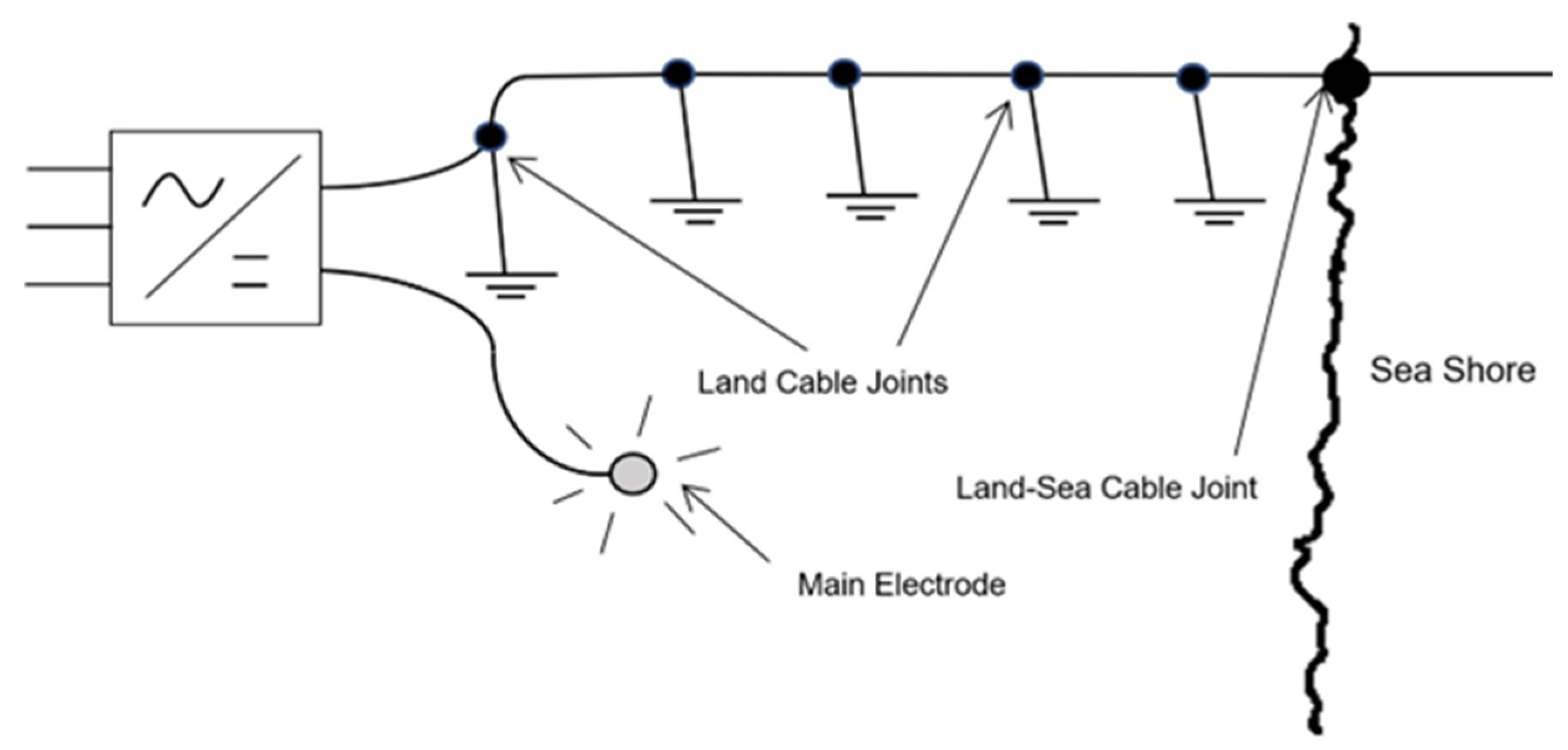
Even if the accuracy of the proposed methods is high, it should be noted that they mainly provide analyses which require a huge computational effort, based on numerical simulations, which is not always affordable by manufacturers which needs answers in a reduced time. For this reason, the proposed analysis will be completely based on an analytical method which relies on the well-known assumption of hemispherical electrodes buried in a uniformly conducting ground. Moreover, the presented work focuses on the analysis of an underground HVDC power line situated considerably closer to the primary ground electrode than the recommended distance of 10 km, as shown in
Figure 1, and explores potential strategies for mitigating interference issues associated with this configuration.
2. Cable Types
For the voltage level of HVDCs (normally within the range 100–500 kV), two main technologies are currently used: mass impregnated cables and extruded cables. The first one uses as an insulating medium a paper tape impregnated with a high-viscosity petroleum oil. In such cases, a lead sheath is always used, and, besides its electrical function, it contains radial oil leakages. In order to prevent lead cracks induced by thermal radial expansions of the sheath, metallic tapes (referred to as reinforcing tapes by the cable industry) are applied directly over the lead sheath. Extruded insulation cables usually use aluminum metallic sheaths which are uses for electrical function only [
22].
High-voltage land cables are manufactured in lengths usually up to 1 km (lengths of more than 1 km are sometimes manufactured) and transported in drums. The cable length in each drum is limited for transportation concerns (weight and drum dimension) or for installation requirements (convenient locations of joint pits). Usually, every 4 to 5 km, the cable sheath will be earthed in order to avoid harmful overvoltages that can arise during transient conditions (cable energization, overvoltages traveling along the cables, etc.) or fault conditions (part of the fault current flowing on the metallic sheath). For such reasons, earthing joints are used where necessary, in which their aim is twofold: to enforce the continuity between two consecutive cable lengths and to guarantee the earthing connection for the metallic sheath [
23,
24,
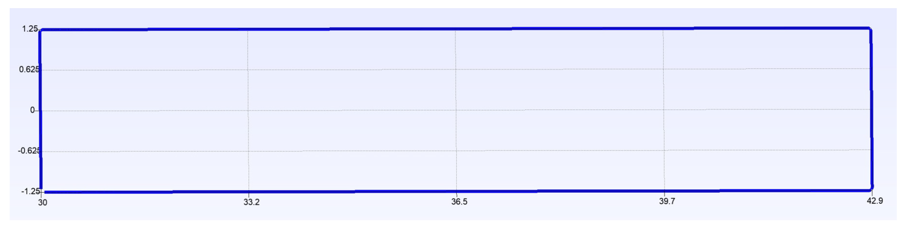
25]. Around the earthing joint pits, a grounding system is created, usually made by simply burying a bare copper-stranded conductor in a rectangular trench, as shown in
Figure 2, positioned around the earthing joint pit to form a closed loop.
3. Proposed Mitigation Techniques
One technique for mitigating stray current circulation, widely used in the electrotechnical industry, is based on the segmentation of any conductive body where the current may freely flow through. For example, in transformers, the basic idea is the lamination, i.e., to subdivide the magnetic core into thin sheets electrically insulated among them, in such a way as to limit the circulation of stray currents to a path completely internal to each sheet, reducing its value. Of course, the thinner the sheet, the greater the reduction of the stray current, even though cost increases and technological difficulties do arise.
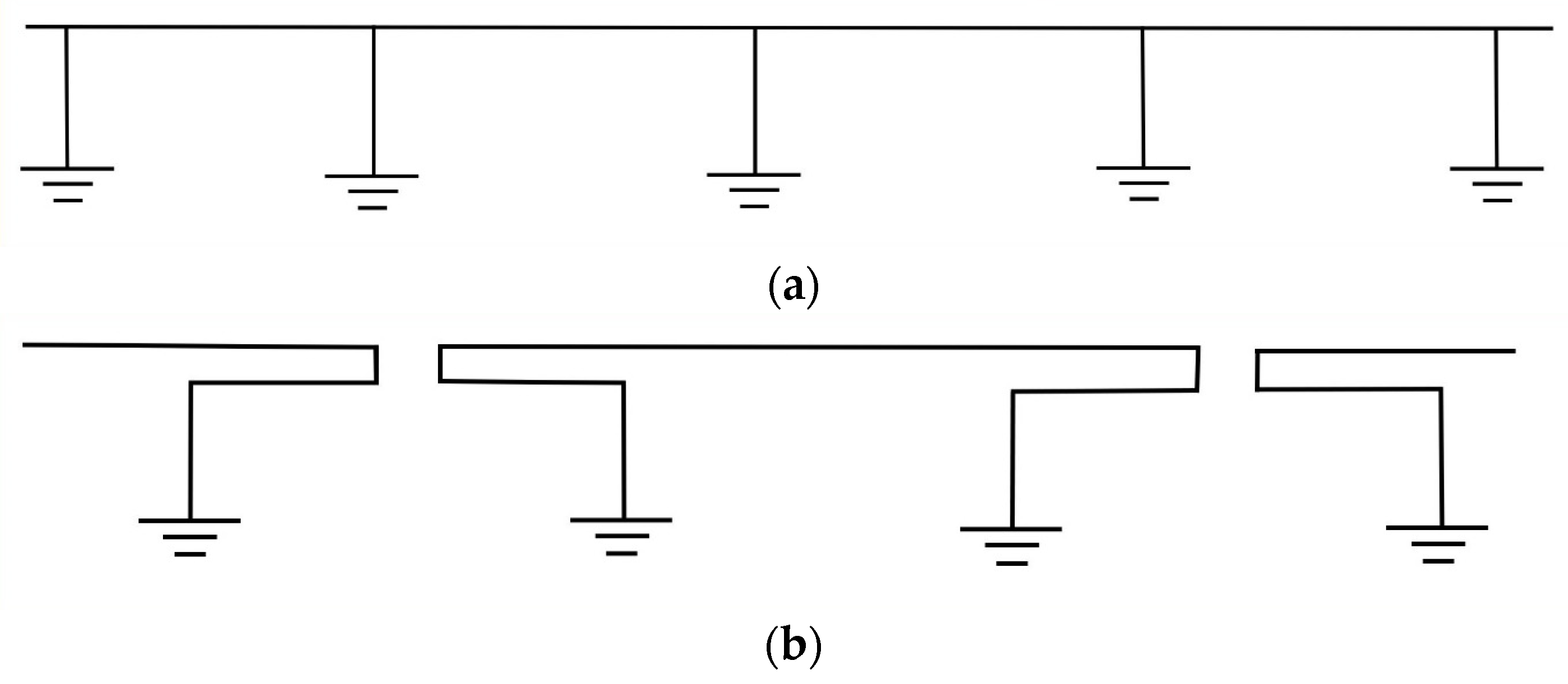
In the specific case of our interest, however, there is more involvement, as the circulation of the current inside the sheath is not due to some failure of the external protective coating, but it is simply a part of the current dispersed by the main ground electrode, picked by the many grounding points distributed along the cable. This can result in the corrosion of the sheath’s grounding electrodes, and possibly in the overheating of the metallic sheath itself. Therefore, even though the idea of segmentation seems promising (
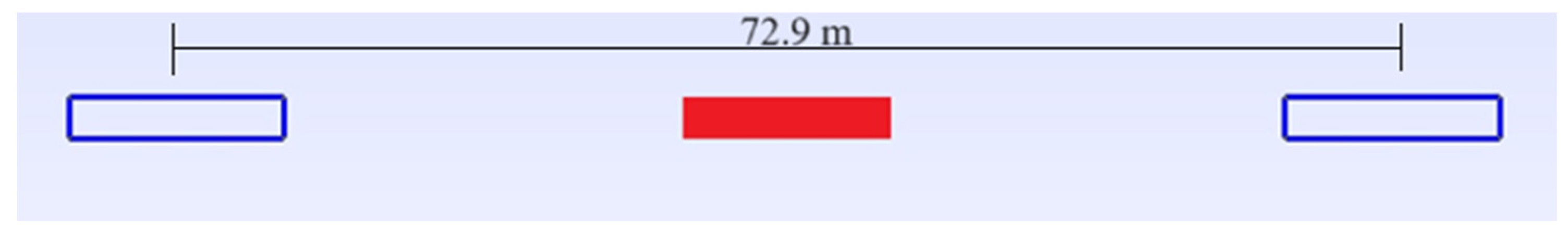
Figure 3), to assess its effectiveness it is necessary to perform some estimations of the order of magnitudes of the current through the sheath with and without segmentation. It is to be remarked that in the original solution, each earthing joint pit was equipped with one ground electrode, while in the proposed segmented solution, each earthing joint bay must be equipped with two ground electrodes, as shown in
Figure 4, where each one is connected to each end of the interrupted sheath. To ensure that the electrical segmentation is effective(i.e., that the two grounding loops do not significantly interfere with each other), they must be buried at a certain distance, which we determined through field simulations. It is important to underline that such a solution can be easily implemented in extruded cables, since the metallic sheath can be sectionalized with the interposition of a small thermoplastic sheath log. On the contrary, on mass impregnated cables, the sectionalization of the lead sheath has never been performed on HVDC cables and, consequently, a solution must be still found. The sectionalization of the reinforcing tapes is possible instead. Such a solution has been applied on the Italy–Montenegro HVDC land cable [
2,
26], in which a small thermoplastic insulation layer has been interposed between the lead sheath and the reinforcing tapes. In such a case, the corrosion process is minimized on the reinforcing tapes which, in any case, plays a vital role for the cable’s lifetime.
4. The Grounding Loop Minimum Distance
Close ground electrodes tend to interact; as we wanted the two adjacent grounding loops to be non-interacting, and the joint pit was 12.7 m long, we chose to locate the two loops with their nearest short edges at 60 m from each other (i.e., 30 m on either side of each earthing joint pit). The centers of the loops were located at 72.9 m from each other. To verify our assumption, we simulated, by using a 1D mesh generator [
27] and a software based on the complex images method [
28], the behavior of just one loop, as in
Figure 2, and of two parallelly connected equal loops, located as in
Figure 4. We obtained the following results: 19.93 Ω for one loop and 10.7 Ω for two loops in parallel; the conclusion is that the difference from one being exactly twice the value of the other is around 7.3%, indicating that the two adjacent ground loops can be considered with good approximation to be electrically independent from each other. In other terms, the proposed separation of 72.9 m from the centers of the loop was adequate for this purpose, as, in the proposed configuration, the adjacent ends of the sheet present in each earthing joint pit are not connected together, but through two series-connected resistances of the earthing loops, having combined values of around 40 Ω.
5. Interference Assessment
To draw general conclusions, it is not advisable to focalize the analysis to a very specific situation, where things may be strongly dependent on the characteristics of the main ground electrode, or the specific positions of the sheath grounding systems.
Therefore, the following approach was developed:
The surface potential rise generated by the main ground electrode was determined by using the simplest possible model (hemispherical electrode, buried in a uniformly conducting ground);
Three lines, characterized by different minimum distances from the main ground electrode and by different layouts, were designed;
The locations of the sheath’s ground electrodes were selected;
Eventually, the magnitude of the current flowing into the sheath was estimated.
Let us examine in detail the aforementioned points: the difference in surface potential rise between two arbitrary points caused by the main electrode can be simply determined by integrating the electric field over a generic hemispheric gaussian surface, by obtaining the following:
where
[Ωm] is the electrical resistivity of the ground,
I [A] is the current injected into the ground by the main electrode, and
and
are the distances between the generic points and the center of the main electrode.
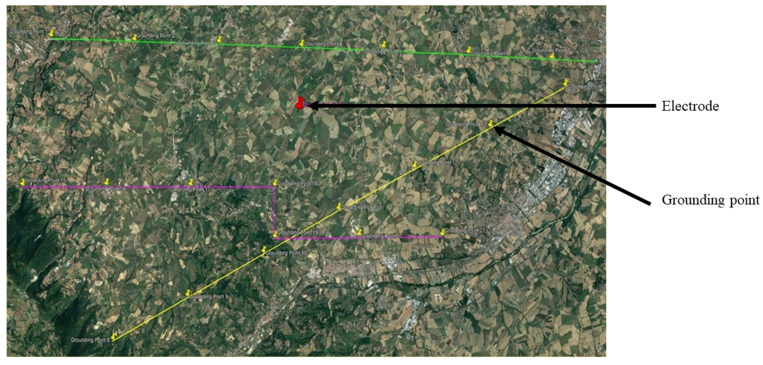
The three hypothetical lines were defined as represented in
Figure 5 below:
The green line is straight, with minimum distance from the main ground electrode of 3 km; the yellow line is straight as well, with a minimum distance of 5 km; the pink line follows a more complex path, with two parts aligned to E/W direction, and one in N/S direction, which is approximately radial with respect to the main electrode. The locations selected for the earthing joint bays are clearly indicated in the picture as “Grounding Point X”. It is to be remarked that, for each grounding point, only one position is indicated: in other words, the coordinates of the two grounding loops are assumed to be coincident with the position of the earthing joint pit, slightly overestimating the voltage between the two loops at the end of one sheath segment.
5.1. Current Estimation
In order to estimate the corrosion rate of the grounding loops, it is necessary to estimate the current flowing through them; in particular, we distinguished the approaches of the two cases, namely unsegmented and segmented.
Main problem data:
Ground electrical resistivity ρ (assumed homogeneous): 325 Ωm;
Electrical resistance of each grounding loop
Rgnd: 20 Ω (
Figure 5: made as an open loop 12.9 m × 2.5 m out of bare copper cord with a diameter of 11 mm, depth 2.3 m, length 30.8 m);
Longitudinal sheath electrical resistance Rsheath: 0.25 Ω/km;
Rated current discharged by the main HVDC grounding electrode I: 350 A;
Max. current discharged by the main HVDC grounding electrode I: 1000 A;
HVDC rated voltage: 200 kV;
Resistance of the main HVDC grounding electrode: 0.16 Ω;
Distance between two subsequent earthing joint pits: 4.5 km.
5.1.1. Case 1: Unsegmented Sheath (Figure 3a)
We can assume that an upper limit for the current flowing through the sheath is given by the GPR (of the main ground electrode) divided by the sum of resistance of the two grounding loops; the resistance of the sheath is negligible with regard to to the former.
Let us consider two grounding loops at 50 km from each other. For a main discharged current equal to 350 A, we calculate that
GPR = 0.16 Ω ∗ 350 A = 56 V:
and the dissipated power per unit length of the sheath is:
If we neglect sheath resistance, the value slightly increases:
Then, the dissipated power per unit length of the sheath becomes:
If the main discharged current is 1000 A, we get
:
Meanwhile, the dissipated power per unit length of the sheath is:
If we neglect sheath resistance, this value also slightly increases:
Then, the dissipated power per unit length of the sheath becomes:
In conclusion, without sheath segmentation, it is reasonable to expect the values of the current flowing through the sheath (and therefore through the grounding loops) to be of a few Amps at the most. The power dissipation on the sheath, limited to a few W/km, does not seem critical at all, considering that the dissipation due to the main cable core is usually in the order of magnitude of 10–20 W/m.
It should be considered that different values of soil conductivities leads to different values of the sheath currents.
It should be noted that GPR and the ground resistance are directly proportional to the soil resistivity, while the sheath resistance is independent of it. As a consequence, considering higher soil resistivities, the current will lead to an asymptotic value obtainable by setting Rsheath = 0 (i.e., 1.4 A according to Equation (4)).
On the other hand, if lower resistivities are considered, the importance of the sheath resistance becomes predominant, leading to lower current values.
5.1.2. Case 2: Segmented Sheath (Figure 3b)
In this case, it is possible to estimate in a simpler way the current flowing through the different sheath segments; in particular, three fictitious line paths were defined. Two of them were straight and characterized by different minimum distances from the main ground electrode (line “1”, green, at 3 km, and line “2”, yellow, at 5 km), and one (line “3”, pink) followed a more complex path with a minimum distance of 3.67 km from the main electrode.
We computed the voltage between the two earthing loops at the end of each sheath segment and the currents were easily obtained by dividing them by the resistance of the two grounding loops and the sheath (i.e., 40 + 1.125 Ω = 41.125 Ω). All computations were made assuming that the main discharged current was equal to 1000 A, and the results are reported in
Table 1,
Table 2 and
Table 3.
The result is that, in the segmented sheath case, we observed voltages lower than 10 V in all cases, leading to currents of, at the most, 150–180 mA, which is one order of magnitude lower than in the unsegmented sheath case.
The dissipated power per unit length of the sheath becomes very small:
5.2. Corrosion Estimation
Grounding loops are made by using bare copper cord, easily corroded when the direction of the dispersed current causes them to work as anodes. In order to schedule the ordinary maintenance needed, it is necessary to estimate their corrosion rate.
The volume of material affected by corrosion (per unit length of the cord, and per unit of time) can be computed as:
where
M is the atomic weight of copper (i.e., 0.06354 kg),
is the current per unit length,
z is the chemical valency of copper (i.e., 2),
F is the Faraday’s constant (i.e., 96,485.3 C/mole), and
is the copper density.
Such a volume is approximately equivalent (for small thicknesses only) to:
where
is the copper cord radius (i.e., 0.0055 m) and
is the thickness of the cord layer lost to corrosion (per unit time).
Combining the two relationships, we can calculate:
To consider the uneven current distribution over the length of the ground loops, we can assume that the maximum value is double that of the average one, which can be simply computed as the dispersed current divided by the loop length; therefore, we can compare the two cases (unsegmented and segmented sheath), both with main discharge currents equal to 1000 A:
5.2.1. Case 1: Unsegmented Sheath
The dispersed current was 4 A and the current per unit length was 0.26 A/m, which led to a corrosion rate of 9.24 mm/year, which is clearly unacceptable as the radius of the conductor forming the grounding loop was 5.5 mm.
5.2.2. Case 2: Segmented Sheath
The dispersed current was 0.15 A and the current per unit length was 9.74 × 10⁻³ A/m which led to a corrosion rate of 0.337 mm/year.
It is apparent that the second solution, considering the radius of the grounding loop conductor and that corrosion rate further increased as such a radius decreases, guarantees the technical reliability of such an approach (even though maintenance should be carried out at least every five years), while the first results were unacceptable.
6. Conclusions
The suggested approach appears to be suitable for effectively decreasing the current flowing through the sheath of a high-voltage direct current (HVDC) cable, which results from the currents being intercepted by the distributed grounding electrode. As a result, the corrosion of the (anodic) copper grounding electrode connected to the cable sheath was expected to occur at a sufficiently slow rate, ensuring the smooth operation of the facility.
The minimal current flowing through the sheath was not expected to cause significant cable overheating, as the power dissipation in the segmented case was less than one hundredth of that in the typical continuous case.
It could be additionally useful to consider, for the manufacturing of sheath grounding electrodes, to use, instead of copper stranded conductors, materials more resistant to corrosion (such as graphite bars or titanium meshes). However, this choice would significantly increase the complexity of the structure, leading to an increase in cost.
A completely different situation is corrosion risk induced on the sheath itself by local damages on the external protective coating of the cable. In this case, the electrical contact is more uncertain, but the crack on the coating is normally very small, and therefore able to lead to local damage in very short times. However, also in this case, if the sheath is segmented, we can expect that the current flowing through the cracks will be greatly reduced with respect to the unsegmented case, ensuring increased safety and operational life. The proposed results are consistent with the existing literature, where outputs have been provided from numerical computations, even if usually further distances from the electrode are considered.
Future developments will regard the possibility of including the cathodic protection system and the corrosion pitting in the proposed methodology by means of a semi-analytical assessment.
Author Contributions
Conceptualization, M.N. and P.M.; methodology, M.N.; software, M.B.; validation, M.N., M.M. and S.P.; formal analysis, M.N.; investigation, D.M.; resources, M.N., M.M. and S.P.; data curation, D.M.; writing—M.N., M.B. and D.M.; writing—review and editing, M.N., M.B. and D.M.; supervision, M.M. and S.P. All authors have read and agreed to the published version of the manuscript.
Funding
This research received no external funding.
Data Availability Statement
Data are not available due to privacy and ethical restrictions.
Conflicts of Interest
The authors declare no conflict of interest.
References
- HITACHI Energy Gotland. Available online: https://www.hitachienergy.com/it/it/about-us/customer-success-stories/the-gotland-hvdc-link (accessed on 22 November 2023).
- Nielsen, M.R. 14.2 Summary of Existing Ground Electrode Designs; CIGRÉ Working Group: Paris, France, 1998. [Google Scholar]
- DL/T 437-2012; Technical Guide of HVDC Earth Electrode System. China Water & Power Press: Beijing, China, 2012.
- IEC TS 62344:2022; Design of Earth Electrode Stations HVDC Links–General Guidelines. International Electrotechnical Commission: Geneva, Switzerland, 2022.
- Tefferi, M.; Li, Z.; Cao, Y.; Uehara, H.; Chen, Q. Novel EPR-Insulated DC Cables for Future Multi-Terminal MVDC Integration. IEEE Electr. Insul. Mag. 2019, 35, 20–27. [Google Scholar] [CrossRef]
- Rosenberg, H. Electric Power HVDC from Land to Off-Shore Structures Utilizing Sea-Electrodes for Return Current Concerns and Precautions with Regard to Environment and Corrosion. In Proceedings of the International Gas Union Research Conference, Copenhagen, Denmark, 17–19 September 2014; pp. 1–7. [Google Scholar]
- CEI EN 50162; Protection against Corrosion by Stray Current from Direct Current Systems. Slovenian Institute for Standardization (SIST): Ljubljana, Slovenia, 2004.
- DONG Naturgas A/S. BalticPipe, Offshore Pipeline Environmental Impact Assessment; Appendix J; Dansk Olie og Naturgas A/S (DONG): Fredericia, Denmark, 2001. [Google Scholar]
- Gong, Y.; Xue, C.; Yuan, Z.; Li, Y.; Dawalibi, F.P. Advanced Analysis of HVDC Electrodes Interference on Neighboring Pipelines. J. Power Energy Eng. 2015, 3, 332–341. [Google Scholar] [CrossRef]
- Charalambous, C.A.; Nikolaidis, A.I. Complete Method to Assess the DC Corrosion Impact on Pipeline Systems During the Planning and Approval Stages of HVDC Systems with Earth Current Return. IEEE Access 2022, 10, 127550–127562. [Google Scholar] [CrossRef]
- EN 12954-2019; General Principles of Cathodic Protection of Buried or Immersed Onshore Metallic Structures. Slovenian Institute for Standardization (SIST): Ljubljana, Slovenia, 2019.
- ISO 21857-2021; Petroleum, Petrochemical and Natural Gas Industries—Prevention of Corrosion on Pipeline Systems Influenced by Stray Currents. International Standards Organization: Geneva, Switzerland, 2021.
- CIGRE W.G. B4.61 General Guidelines for HVDC Electrode Design 2017.
- Wu, Y.; Cai, H. Discussion on the Safe Distance Between HVDC Electrode and Pipeline. IEEE Access 2023, 11, 28090–28102. [Google Scholar] [CrossRef]
- Li, Z.; Niasar, M.G.; Kavian, M.; de Wild, F. Analysis of Stray Current Corrosion on Buried Pipeline Due to HVDC Grounding Current. In Proceedings of the 2020 IEEE 29th International Symposium on Industrial Electronics (ISIE), Delft, The Netherlands, 17–19 June 2020; IEEE: Piscataway, NJ, USA, 2020; pp. 1233–1238. [Google Scholar]
- Cao, G.; Gu, Q.; Jiang, Y.; Li, Y.; Mao, J.; Xiu, L.; Wang, X.; Jiang, Z. Current Interference of HVDC Ground Electrode to Buried Pipelines and Its Personal Safety Distance. Nat. Gas Ind. B 2019, 6, 427–434. [Google Scholar] [CrossRef]
- Chen, X.; Li, L. Study on the Interference of the HVDC Transmission Grounding Electrode to the Pipeline Cathodic Protection System. ACS Omega 2023, 8, 22088–22098. [Google Scholar] [CrossRef] [PubMed]
- Wuxi, B.; Hongyuan, C.; Zhenjun, L.; Youwen, J.; Lingli, L.; Yabo, H. HVDC Interference to Buried Pipeline: Numerical Modeling and Continuous P/S Potential Monitoring; OnePetro: Richardson, TX, USA, 2016. [Google Scholar]
- Chao, Y.; Jianliang, L.; Zili, L.; Shouxin, Z.; Long, D.; Chengbin, Z. Study on Interference and Protection of Pipeline Due to High-Voltage Direct Current Electrode. Corros. Rev. 2019, 37, 273–281. [Google Scholar] [CrossRef]
- Yu, Z.; Liu, L.; Wang, Z.; Li, M.; Wang, X. Evaluation of the Interference Effects of HVDC Grounding Current on a Buried Pipeline. IEEE Trans. Appl. Supercond. 2019, 29, 1–5. [Google Scholar] [CrossRef]
- Mishra, M. HVDC & HVAC Powerline Interference on Cross Country Pipeline: A Case Study; OnePetro: Richardson, TX, USA, 2021. [Google Scholar]
- Mazzanti, G.; Marzinotto, M. Extruded Cables for High-Voltage Direct-Current Transmission: Advances in Research and Development; IEEE: Piscataway, NJ, USA, 2013. [Google Scholar]
- Working Group 07 of Study Committee 21. The Design of Specially Bonded Cable Systems. 1973. Available online: https://www.e-cigre.org/publications/detail/elt-028-2-the-design-of-specially-bonded-cable-systems.html (accessed on 22 November 2023).
- Working Group 07 of Study Committee 21. The Design of Specially Bonded Cable Systems (Second Part). 1976. Available online: https://www.e-cigre.org/publications/detail/elt-047-3-the-design-of-specially-bonded-cable-systems-second-part.html (accessed on 22 November 2023).
- Working Group 07 of Study Committee 21. Guide to the Protection of Specially Bonded Cable Systems against Sheath Overvoltages. 1990. Available online: https://www.e-cigre.org/publications/detail/elt-128-2-guide-to-the-protection-of-specially-bonded-cable-systems-against-sheath-overvoltages.html (accessed on 22 November 2023).
- Fukushima, S.; Okuda, M.; Kaneda, K.; Garzi, G.; Maddaloni, V.; Gareth, B.; Cortese, M. Experience of MONITA HVDC Link Project. In Proceedings of the 15th International Conference on Developments in Power System Protection (DPSP 2020), Liverpool, UK, 9–12 March 2020; IET: London, UK, 2020; pp. 1–6. [Google Scholar]
- Geuzaine, C.; Remacle, J.-F. Gmsh: A 3-D Finite Element Mesh Generator with Built-in Pre- and Post-Processing Facilities. Int. J. Numer. Methods Eng. 2009, 79, 1309–1331. [Google Scholar] [CrossRef]
- Brignone, M.; Qombovani, A.K.; Molfino, P.; Nervi, M. An Algorithm for the Semi-Analytical Computation of Fields Emitted in Layered Ground by HVDC Electrodes. In Proceedings of the 2016 Power Systems Computation Conference (PSCC), Genoa, Italy, 20–24 June 2016; pp. 1–6. [Google Scholar]
| Disclaimer/Publisher’s Note: The statements, opinions and data contained in all publications are solely those of the individual author(s) and contributor(s) and not of MDPI and/or the editor(s). MDPI and/or the editor(s) disclaim responsibility for any injury to people or property resulting from any ideas, methods, instructions or products referred to in the content. |
© 2023 by the authors. Licensee MDPI, Basel, Switzerland. This article is an open access article distributed under the terms and conditions of the Creative Commons Attribution (CC BY) license (https://creativecommons.org/licenses/by/4.0/).


 ,
, 


