Article

An Active Power Dynamic Oscillation Damping Method for the Grid-Forming Virtual Synchronous Generator Based on Energy Reshaping Mechanism

1
Key Laboratory of Advanced Manufacturing and Automation Technology, Education Department of Guangxi Zhuang Autonomous Region, Guilin University of Technology, Guilin 541006, China
2
School of Electrical Engineering, Shandong University, Jinan 250002, China
*
Author to whom correspondence should be addressed.
Energies 2023, 16(23), 7723; https://doi.org/10.3390/en16237723
Submission received: 14 September 2023 / Revised: 14 November 2023 / Accepted: 16 November 2023 / Published: 23 November 2023

Abstract

:
The grid-forming virtual synchronous generator (GFVSG) with large virtual inertia can provide a friendly grid-connected operational mode for power electronic converters, but it may also introduce the active power dynamic oscillation problems similar to traditional synchronous generators. In view of this, the dynamic equivalent circuit model of the GFVSG grid-tied active power-angle is established firstly, and, then, the understanding of the GFVSG active power oscillations under variable disturbances is revealed from the perspective of circuit energy flow in this paper. On this basis, an active power dynamic oscillation damping method based on an energy reshaping mechanism for the GFVSG is proposed, and a parameter design method using the second-order equivalent reduced-order control model is given. The MATLAB 2016a simulation as well as experimental test platforms of a 100 kV·A GFVSG grid-connected system are established, then, both the feasibility and effectiveness of the proposed active power dynamic oscillation damping method are verified by using the simulation and experimental comparison results.

1. Introduction

The grid-forming virtual synchronous generator (GFVSG) can provide a certain degree of voltage regulation and inertial support for the grid-connected operation of power electronic converters (PECs) by simulating the primary voltage equation and rotor motion equation of traditional synchronous generators (TSGs), which improves the operation reliability of large-scale renewable energy integration to the power grid, and has attracted wide attention in recent years [1,2]. However, GFVSG with large virtual inertia will inevitably exhibit the grid-connected active power dynamic oscillation problems similar to TSGs when dealing with different disturbances such as the active power command step and the power grid frequency change [3,4]. As the overcurrent tolerance of PECs is usually weak, the large instantaneous current in the GFVSG active power dynamic oscillation process is easy to cause overcurrent protection action or even equipment damage to PECs, thus reducing the GFVSG operation reliability [5].
Damping control methods play a very important role in suppressing the dynamic oscillations of the GFVSG grid-connected active power and its output frequency, which mainly includes three types: the adaptive parameter adjustment method, feedback channel-based compensation method, and feedforward path compensation method [6]. Among them, the adaptive parameter adjustment method improves the ability of GFVSG to suppress its active power dynamic oscillation through the adaptive adjustment of virtual inertia, virtual damping, virtual impedance, or primary frequency modulation parameters. In [7,8], the adaptive adjustment method of the virtual inertia parameter is achieved by detecting the change rule of the GFVSG output frequency. In [9,10], the damping of the GFVSG grid-connected system is further optimized by taking advantage of the fact that both the virtual inertia and the virtual damping parameters of GFVSG can be adjusted adaptively. The damping optimization method of a GFVSG grid-connected system based on an adaptive virtual impedance scheme is proposed in [11]. A GFVSG transient damping control algorithm based on the adaptive adjustment of the GFVSG primary frequency modulation parameter according to different frequency segments is achieved in [12]. It is worth pointing out that the adaptive parameter adjustment method in [7,8,9,10,11,12] has the disadvantages of the parameter adjustment range being difficult to determine and the design process being complicated, and the nonlinear change in adaptive parameters will also affect the operation stability of the GFVSG grid-connected system.
The feedback channel-based compensation method mainly introduces the angular frequency variation or the active power variation into the GFVSG control loop through a feedback channel to suppress the GFVSG active power dynamic oscillation. In [13,14], a first-order low-pass filter (LPF) is used to detect the angular frequency dynamic deviation, which is then fed back to the GFVSG active power command through a proportional link. In [15,16], the dynamic deviation between the GFVSG angular frequency and the grid angular frequency detected using phase locked loop (PLL) is fed back to the GFVSG control loop via a proportional link to simulate the function of the damping windings of TSGs, but the introduction of the PLL will create an undesired negative damping effect on the GFVSG stable operation. In [17,18], both the dynamic variations in the angular frequency and the active power are introduced into the GFVSG control loop through feedback channels to enhance the dynamic damping of the system. It is worth pointing out that, although the above-mentioned damping methods based on feedback channel compensation can effectively suppress the GFVSG active power dynamic oscillation, their damping effects only take effect after the deviation of the controlled variable, which has a certain passivity. Therefore, for a GFVSG grid-tied system with large virtual inertia, if the system disturbance is frequent and large enough, continuous active power dynamic oscillations may be observed in the dynamic response process, which requires a long regulation time to ensure that the GFVSG grid-connected system reaches a new steady state [19].
The damping method based on feedback channel compensation is biased towards passive feedback tracking, while the damping method based on feedforward path compensation is biased towards active feedforward compensation. In [20,21], the GFVSG angular frequency variation is fed forward to its reactive power control loop by referring to the principle of a power system stabilizer, but the dynamic coupling between the active power and reactive power control loops is induced, so that the complex nonlinear characteristics may be introduced into the dynamic response process of the system. In [22], a GFVSG damping optimization method based on the active power command feedforward is proposed, but the control parameter design has the problems of a high dependence on the accuracy of the line impedance parameters and poor applicability to the scenario of the power grid frequency disturbance. In [23,24], a GFVSG damping improved control strategy based on phase feedforward compensation is proposed from the perspective of a reconstructed damping controller, which effectively solves the problem of the high dependence on the system parameters that existed in [22]. However, the open-loop gain of the GFVSG control system has a reduced decline slope in the high frequency band, which weakens the ability of the GFVSG system to resist high-frequency noise. In [25], two GFVSG damping improved control methods based on the active-power differential feedback compensation (ADFC) and the active-power differential feedforward compensation (ADFF) are proposed to enhance the ability to suppress high-frequency noise, but the active power regulation time or the frequency overshoot of the GFVSG system still need to be further improved.
To address the above issues, this paper further proposes an active power dynamic oscillation damping method based on energy reshaping mechanism (ERM) for GFVSG (hereafter referred to as ERM-GFVSG). ERM-GFVSG enhances its ability to suppress the active power dynamic oscillation by introducing the feedback channel-based compensation damping method using the dynamic variations in the angular frequency and the active power into the GFVSG control structure. Compared with the existing damping control methods, the proposed ERM-GFVSG significantly obtains a better disturbance rejection ability and dynamic response performance. The main contributions made in this paper as well as their significance are summarized as follows:
(1)
Both the closed-loop small signal model and the dynamic equivalent circuit model of GFVSG are established successively. Therefore, it reflects that the active power command step and the power grid frequency disturbance are regarded as excitation sources to inject dynamic oscillation energy into the GFVSG from the perspective of circuit energy flow.
(2)
Compared with GFVSG, ERM-GFVSG increases the total amount of the consumed energy and the consumption speed of the dynamic oscillation energy on the premise of keeping the total dynamic oscillation energy and the total stored energy unchanged. Accordingly, it is equivalent to increasing the system damping, so as to enhance the ability of suppressing the active power dynamic oscillation.
(3)
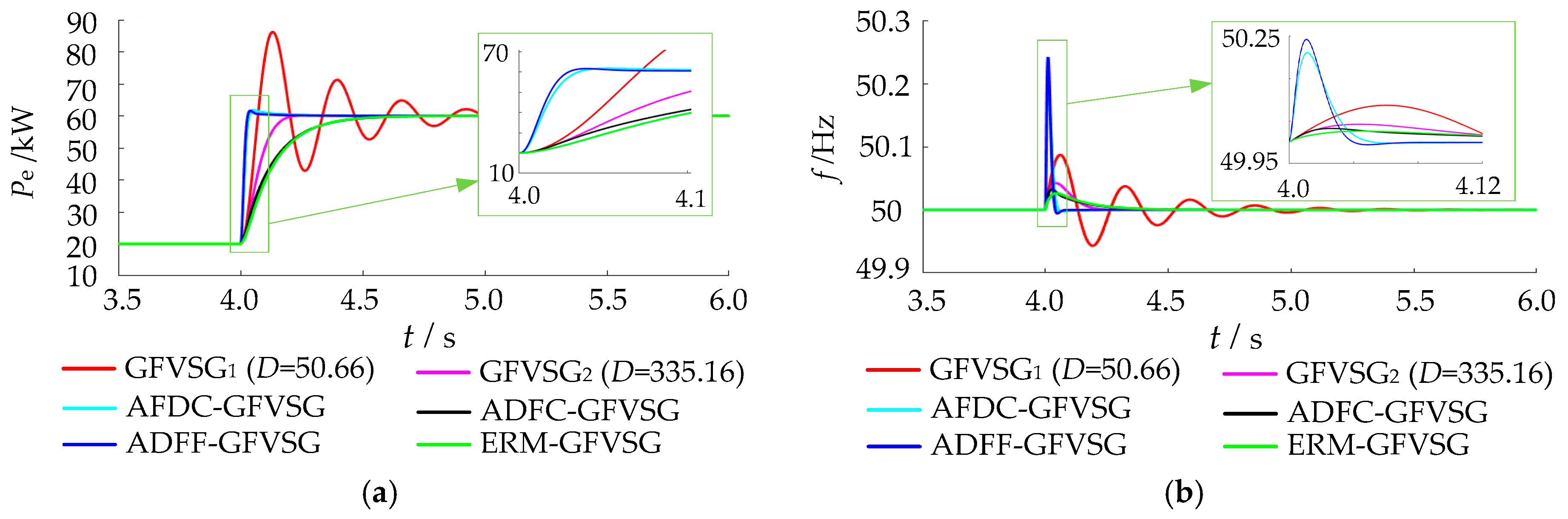
The proposed active power dynamic oscillation damping method only works in the dynamic response process, so it does not affect the active power steady-state deviation. Practically, compared with the existing methods, ERM-GFVSG has the smallest frequency overshoot under the active power command step and the shortest active power regulation time under the power grid frequency disturbance.
The rest of the paper is organized as follows. In Section 2, the closed-loop small signal model as well as the dynamic equivalent circuit model of GFVSG are established and the active power dynamic oscillation mechanism is analyzed. In Section 3, the ERM-GFVSG control method is proposed and its parameter design method is presented. In Section 4, the simulation and experimental comparison results are provided. Finally, the conclusions are drawn in Section 5.

2. Control Model and Active Power Dynamic Oscillation Mechanism of GFVSG

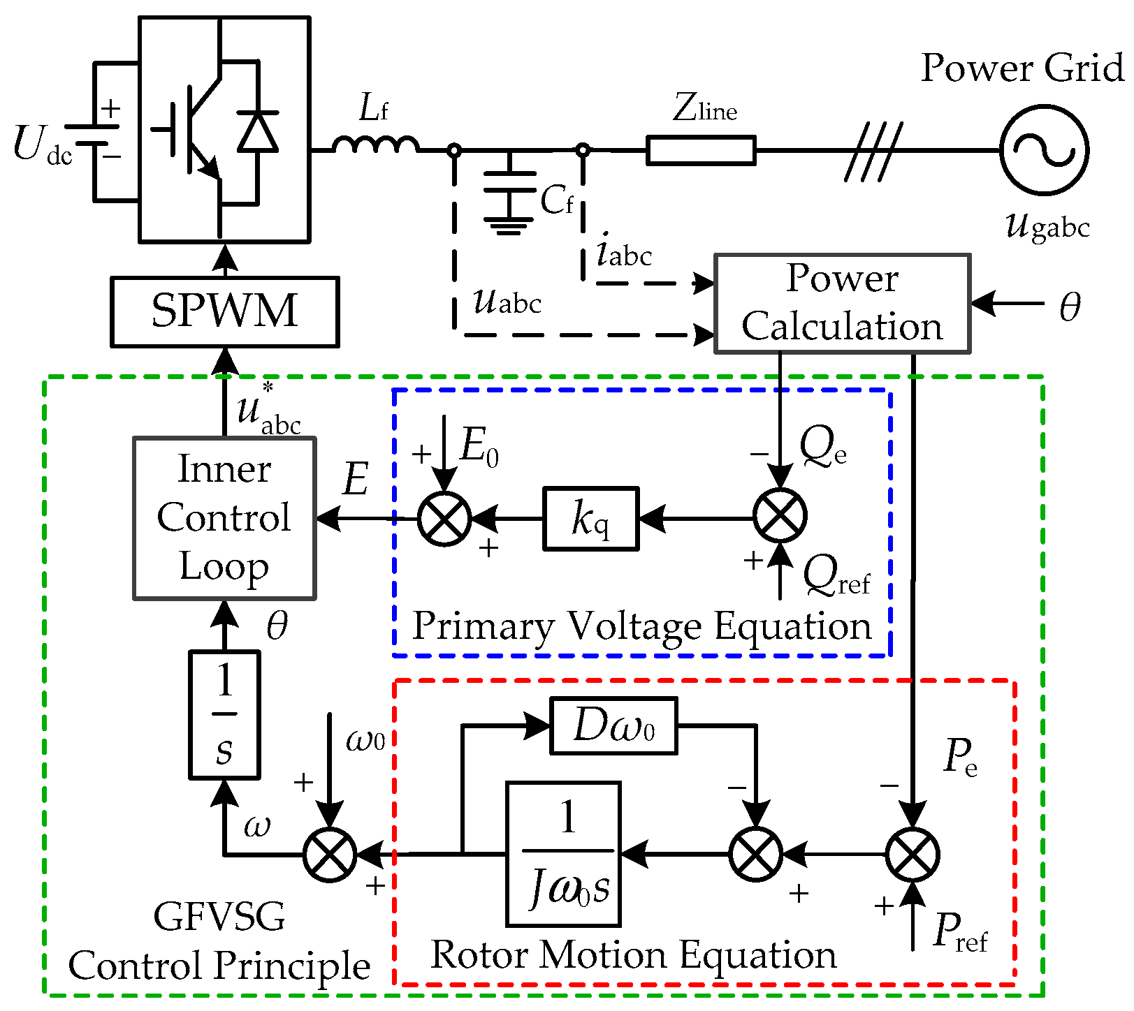
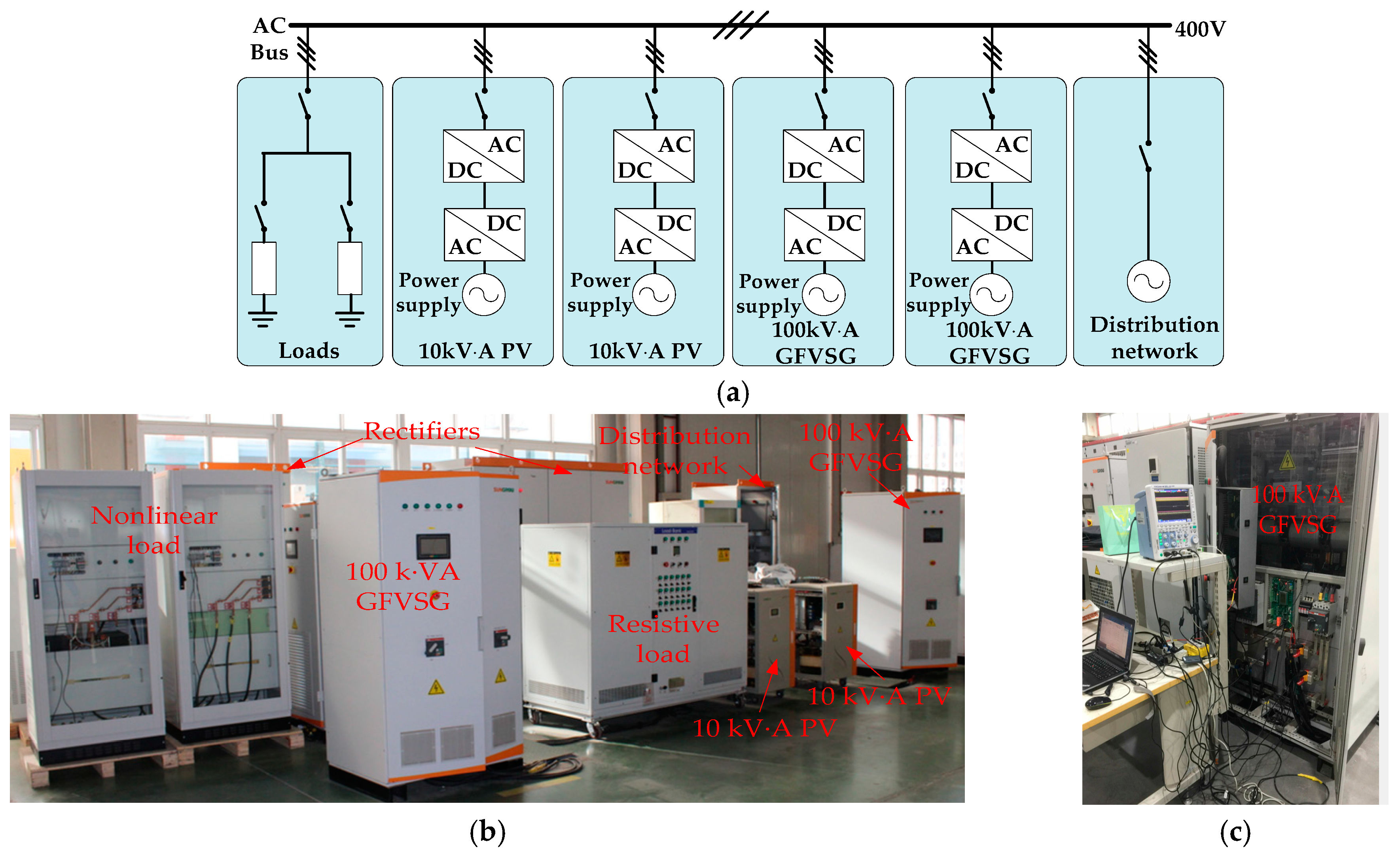
2.1. Overview of GFVSG Grid-Connected System

Figure 1 illustrates the circuit topology and the control block diagram of GFVSG grid-connected system [4].
The power stage consists of a DC source, denoted by Udc, a line equivalent impedance Zline, a three-phase PEC and an LC filter, where Lf and Cf are the filter inductor and filter capacitor, respectively. uabc, iabc, ugabc, and u abc * are the output voltage, output current, power grid voltage, and output voltage command, respectively. The GFVSG control principle mainly consists of the power calculation, the stator electrical equation, the rotor motion equation, and the inner control loop. A traditional cascaded voltage and current controller can be used in the inner control loop to achieve a better dynamic response performance [5]. According to Figure 1, the rotor motion equation and the primary voltage equation of GFVSG can be expressed as follows:
P ref P e = J ω 0 d ( ω ω 0 ) d t + D ω 0 ( ω ω 0 ) ,
E = E 0 + k q ( Q ref Q e ) ,
where Pref, Pe, Qref, and Qe are the active power command, active power, reactive power command, and reactive power, respectively; J, D, ω0, and ω are the virtual inertia, virtual damping, rated angular frequency, and output angular frequency, respectively; kq, E0, and E are the primary voltage regulation coefficient, rated voltage amplitude, and output voltage amplitude, respectively.
Note that this paper focuses on the GFVSG active power dynamic oscillation derived from the active power control loop rather than the reactive power control loop. Taking into account the AC filter inductor or a transformer on the power grid side, it is assumed that the line equivalent impedance Zline is inductive, leading to the control loops of the active power and reactive power being decoupled. Meanwhile, the control bandwidth of the inner control loop is commonly designed to be much higher than that of the outer power control loop to maintain the command tracking and stability [6]. To simplify the theoretical analysis, the reactive power control loop and the inner control loop are omitted in the subsequent analysis.

2.2. Small Signal Model of GFVSG and Its Active Power Dynamic Oscillation Analysis

The equivalent power transmission model of GFVSG grid-connected system is illustrated in Figure 2, where XL, RL, Ug, and δ are the line reactance, line resistance, power grid voltage amplitude, and power factor angle, respectively.
In this paper, the line equivalent impedance Zline is assumed to be purely inductive, neglecting the line resistance RL, to simplify the system model. From Figure 2, the active power Pe of GFVSG can be expressed as
P e = 3 U g E 2 X L δ = K δ = 3 U g E ( ω ω g ) 2 X L s ,
where K = (3UgE)/(2XL) and ωg are the synchronization voltage coefficient and power grid angular frequency, respectively. By combining Equations (1) and (3), the GFVSG closed-loop small signal control model can be obtained as shown in Figure 3, where “∆” denotes the small signal disturbance amount.
According to Figure 3, it is not difficult to find that the change in active power command ∆Pref can be regarded as an internal disturbance, while the change in power grid angular frequency ∆ωg can be regarded as an external disturbance. Both the ∆Pe and the ∆ω of GFVSG are affected by the two disturbances ∆Pref and ∆ωg, and the corresponding closed-loop transfer functions can be obtained as follows:
{ G 1 _ G ( s ) = Δ P e ( s ) Δ P ref ( s ) | Δ ω g = 0 = K J ω 0 s 2 + D ω 0 s + K G 2 _ G ( s ) = Δ P e ( s ) Δ ω g ( s ) | Δ P ref = 0 = ( J ω 0 s + D ω 0 ) K J ω 0 s 2 + D ω 0 s + K ,
{ G 3 _ G ( s ) = Δ ω ( s ) Δ P ref ( s ) | Δ ω g = 0 = s J ω 0 s 2 + D ω 0 s + K G 4 _ G ( s ) = Δ ω ( s ) Δ ω g ( s ) | Δ P ref = 0 = K J ω 0 s 2 + D ω 0 s + K ,
where the subscript “G” or the later “E” are applied to declare that the function or variable is definitely used for the GFVSG or ERM-GFVSG. According to Equation (4), the active power steady-state deviation ∆Pe0 (∆Pe0 = ∆Pe − ∆Pref) of GFVSG can be obtained as follows:
Δ P e 0 = Lim s 0 G 2 ( s ) Δ ω g = D ω 0 Δ ω g ,
According to Equations (4) and (5), it is found that the GFVSG closed-loop control system is a typical second-order oscillation system, and its characteristic function is as follows:
J ω 0 s 2 + D ω 0 s + K = 0 ,
where the natural oscillation angular frequency ωn_G and its damping ratio ξG of the GFVSG closed-loop control system are expressed as
ω n _ G = K / ( J ω 0 ) , ξ G = 0.5 D ω 0 1 / ( K J ω 0 ) ,
It can be seen from Equations (6) and (8) that both ωn_G and ξG decrease with the increase in J, which represents the slower dynamic response speed and the more intense dynamic oscillation of Pe or ω under the two disturbances of ∆Pref and ∆ωg. In addition, both ξG and ∆Pe0 increase with the increase in D, that is, the stronger the ability to inhibit the power active dynamic oscillation, but the larger the steady-state deviation of the active power.

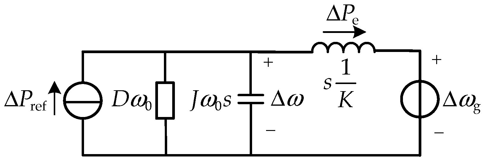
2.3. Equivalent Circuit Model of GFVSG and Its Active Power Dynamic Oscillation Analysis

According to Figure 3, the differential equations can be obtained as follows:
Δ ω Δ ω g = 1 K d Δ P e d t ,
Δ P ref Δ P e D ω 0 Δ ω = J ω 0 d Δ ω d t ,
Table 1 shows the analogy relationships between the electromechanical and electromagnetic variables [26]. In Table 1, L, C, u, i, and Ψ are the inductance, capacitance, voltage, current, and flux linkage, respectively.
According to Table 1, Equations (9) and (10) can be likened to the circuit equations expressed by Equations (11) and (12), respectively.
L d i L d t = u L ,
C d u C d t = i ref i L u C R ,
where uL, iL, uC, and R = 1/(0) are the inductance voltage, inductance current, capacitance voltage, and resistance, respectively. According to Equations (11) and (12), the GFVSG closed-loop small-signal control model in Figure 2 can be likened to the dynamic equivalent circuit model shown in Figure 4, where ∆Pref, 0, s0, s/K, ∆Pe, ∆ω, and ∆ωg are equal to the current source, conductance, capacitive susceptance, inductive reactance, equivalent current flowing through the inductor 1/K, electromotive force, and voltage source, respectively, and ∆Pref and ∆ωg can also be used as two excitation sources in the GFVSG dynamic equivalent circuit.
According to Figure 4, the dynamic oscillation energies W1 and W2 injected into the circuit by the current source ∆Pref and the voltage source ∆ωg can be expressed as
W 1 = 0 t Δ P ref Δ ω d t , W 2 = 0 t Δ P e Δ ω g d t ,
It is worth pointing out that, in the GFVSG dynamic response process, ∆Pref and ∆ω always maintain the same sign, while ∆Pe and ∆ωg always maintain a different sign. Therefore, the integral calculation results W1 and W2 are always positive, which means that the total dynamic oscillation energy (W1 + W2) is always injected into the equivalent circuit under the two disturbances of ∆Pref and ∆ωg. In Figure 4, W3, W4, and W5 are the energy consumed by the equivalent resistance 1/(0), the kinetic energy stored by the equivalent capacitance (0), and the potential energy stored by the equivalent inductor (1/K), respectively. Similarly, W3, W4, and W5 can be expressed as
W 3 = 0 t D ω 0 Δ ω 2 d t , W 4 = J ω 0 Δ ω 2 2 , W 5 = Δ P e 2 2 K ,
By multiplying Equation (9) by ∆Pe and Equation (10) by ∆ω, and then integrating both sides of the equation over time, the correspondences between Equations (13) and (14) can be acquired, as shown in Equation (15).
0 t Δ P ref Δ ω d t 0 t Δ P e Δ ω g d t I n j e c t e d   e n e r g y ( W 1 + W 2 ) = J ω 0 Δ ω 2 2 + Δ P e 2 2 K S t o r e d   e n e r g y ( W 4 + W 5 ) + 0 t D ω 0 Δ ω 2 d t C o n s u m e d   e n e r g y ( W 3 ) ,
According to Equation (15), it is not difficult to find that the dynamic equivalent circuit of GFVSG can meet the law of the energy conservation, that is, the total dynamic oscillation energy (W1 + W2) injected into the circuit by the two disturbances of ∆Pref and ∆ωg is equal to the sum of the consumed energy W3 and the total stored energy (W4 + W5), where W4 and W5 can be converted into each other. Meanwhile, the value of W3 represents the capacity to consume the total dynamic oscillation energy, that is, due to the existence of the equivalent resistance 1/(0), the total dynamic oscillation energy is decreasing continuously and the system eventually reaches a new steady state.
It can also be found from Equation (15) that under a certain disturbance of ∆Pref or ∆ωg, the larger the J value of GFVSG, the larger the stored energy W4, and the longer the system takes to consume W4, so the regulation time of the system will be longer. The larger the D value of GFVSG, the larger the consumed energy W3, and the shorter the system takes to consume (W1 + W2), the stronger the ability to suppress the system dynamic oscillation. The above results are in one-to-one correspondence with the conclusions from Equation (8).
In summary, for GFVSG grid-connected systems, the active power dynamic oscillation can be suppressed by the following four main methods. First, the method of reducing the stored energy, that is, the adaptive parameter adjustment method using adaptive virtual inertia, adaptive virtual impedance, or other adaptive parameters. Second, the method of reducing the injected energy, that is, the feedforward path compensation method using active power command, grid angular frequency, or other variables. Third, the method of increasing consumed energy, that is, the feedback channel-based compensation method using angular frequency change, active power change, or other changes. Fourth, any combination of the above three methods.

3. The Proposed ERM-GFVSG Control Method

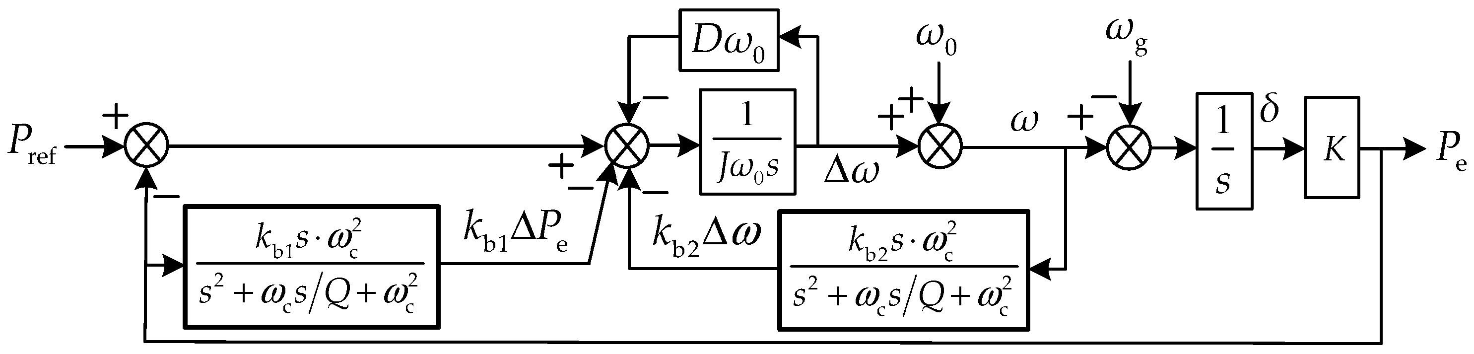
3.1. Control Principle of ERM-GFVSG

To solve the problem of the active power dynamic oscillation existing in the GFVSG grid-connected system, the third method of increasing the consumed energy is used by ERM-GFVSG. In other words, ERM-GFVSG introduces a feedback channel-based compensation method, using the dynamic variations in the angular frequency and the active power in the GFVSG control structure to improve its ability to suppress the active power dynamic oscillation. For ERM-GFVSG, the differential Equations (9) and (10) can be rewritten as follows:
Δ ω Δ ω g k b 1 Δ P e = 1 K d Δ P e d t ,
Δ P ref Δ P e D ω 0 Δ ω k b 2 Δ ω = J ω 0 d Δ ω d t ,
where kb1 and kb2 are the active power feedback parameter and angular frequency feedback parameter, respectively. According to Table 1, Equations (16) and (17) can also be likened to the circuit equations expressed by Equations (18) and (19), respectively.
L d i L d t = u L k b 1 i L U I ,
C d u C d t = i ref i L u C R u C k b 2 I U ,
where UI and IU are the current controlled voltage source (CCVS) and voltage controlled current source (VCCS), respectively. According to Equations (18) and (19), the dynamic equivalent circuit model of the ERM-GFVSG grid-connected system can also be maintained, as shown in Figure 5, where kb1 is equal to the resistance, and kb2 is equal to the conductance. W6 is the energy consumed by the equivalent resistance kb1, and W7 is the energy consumed by the equivalent resistance (1/kb2). Similarly, W6 and W7 can be expressed as
W 6 = 0 t k b 1 Δ P e 2 d t , W 7 = 0 t k b 2 Δ ω 2 d t ,
Next, by multiplying Equation (16) by ∆Pe and Equation (17) by ∆ω, and then integrating both sides of the equation over time, the following can be obtained:
0 t Δ P ref Δ ω d t 0 t Δ P e Δ ω g d t I n j e c t e d   e n e r g y ( W 1 + W 2 ) = J ω 0 Δ ω 2 2 + Δ P e 2 2 K S t o r e d   e n e r g y ( W 4 + W 5 ) + 0 t D ω 0 Δ ω 2 d t + 0 t k b 1 Δ P e 2 d t + 0 t k b 2 Δ ω 2 d t C o n s u m e d   e n e r g y ( W 3 + W 6 + W 7 ) > W 3 ,
Compared with Equations (15) and (21), it can be seen that ERM-GFVSG can effectively increase the consumption speed of (W1 + W2) by increasing the total consumed energy from W3 to (W3 + W6 + W7) on the premise of keeping (W1 + W2) and (W4 + W5) unchanged. That is, it is equivalent to increasing the value of D to enhance the damping of the GFVSG grid-connected system and its ability to suppress the active power dynamic oscillation.
In this paper, the two fluctuation variables ∆Pe and ∆ω contained in Equation (21) are extracted by second-order LPFs, which are then fed back to the ERM-GFVSG active power command through kb1 and kb2, respectively. Therefore, by combining Equations (16) and (17), the ERM-GFVSG closed-loop small signal control model can be obtained as shown in Figure 6. In Figure 6, ωc and Q are the cutoff angular frequency and quality factor of the second-order LPF, respectively. The second-order LPF is introduced to effectively filter out the high-frequency harmonics generated by differential operation. It is worth pointing out that the purpose of moving the feedback variable (kb1Pe) forward to the virtual inertia control link is to filter (kb1Pe) again by using the first-order LPF 1/(sJω0 + 0), which is composed of the virtual inertia link and the virtual damping link on the forward channel in Figure 6.

3.2. Parameter Design Method of ERM-GFVSG

Likewise, according to the closed-loop small signal control model of ERM-GFVSG grid-connected system shown in Figure 6, the closed-loop transfer functions of ERM-GFVSG can be obtained as follows:
{ G 1 _ E ( s ) = Δ P e ( s ) Δ P ref ( s ) | Δ ω g = 0 = K s 2 + K ω c / Q s + K ω c 2 J ω 0 s 4 + M 3 s 3 + M 2 s 2 + M 1 s + K ω c 2 G 2 _ E ( s ) = Δ P e ( s ) Δ ω g ( s ) | Δ P ref = 0 = K J ω 0 s 3 + N 2 s 2 + N 1 s + D ω 0 K ω c 2 J ω 0 s 4 + M 3 s 3 + M 2 s 2 + M 1 s + K ω c 2 ,
{ G 3 _ E ( s ) = Δ ω ( s ) Δ P ref ( s ) | Δ ω g = 0 = s 3 + ω c / Q s 2 + ω c 2 s J ω 0 s 4 + M 3 s 3 + M 2 s 2 + M 1 s + K ω c 2 G 4 _ E ( s ) = Δ ω ( s ) Δ ω g ( s ) | Δ P ref = 0 = K s 2 + K ( ω c / Q + k b 1 ω c 2 ) s + K ω c 2 J ω 0 s 4 + M 3 s 3 + M 2 s 2 + M 1 s + K ω c 2 ,
where M1 = ωc(0ωc + Kkb1ωc + K/Q); M2 = 0ωc2 + 0ωc/Q + K+kb2ωc2; M3 = ω0(c/Q + D); N1 = c(0ωc + 0/Q + kb2ωc); and N2 = 0(c/Q + D). Referring to the parameter selection principle of the second-order LPF in [25], on the one hand, when the filtering time constant τ of the first-order LPF 1/(τs + 1) is set to τ = 1/ωc, a second-order LPF can be equivalently reduced to a first-order LPF. On the other hand, to weigh the filtering effect, dynamic response speed, and the influence on the system operating stability of the second-order LPF, τ = 0.007 s (ωc = 1/τ = 142.86 rad /s) and Q = 0.5 are set here to simplify the theoretical analysis process and the system parameter design method. In view of this, Equations (22) and (23) after the order reduction are approximately as follows:
{ G 1 _ E ( s ) = Δ P e ( s ) Δ P ref ( s ) | Δ ω g = 0 K τ s + K J ω 0 τ s 3 + M 21 s 2 + M 11 s + K G 2 _ E ( s ) = Δ P e ( s ) Δ ω g ( s ) | Δ P ref = 0 K J ω 0 τ s 2 + N 11 s + D ω 0 K J ω 0 τ s 3 + M 21 s 2 + M 11 s + K ,
{ G 3 _ E ( s ) = Δ ω ( s ) Δ P ref ( s ) | Δ ω g = 0 τ s 2 + s J ω 0 τ s 3 + M 21 s 2 + M 11 s + K G 4 _ E ( s ) = Δ ω ( s ) Δ ω g ( s ) | Δ P ref = 0 K ( τ + k b 1 ) s + K J ω 0 τ s 3 + M 21 s 2 + M 11 s + K ,
where M21 = 0 + 0τ + kb2; M11 = 0 + Kkb1 + ; and N11 = K(0 + 0τ + kb2). By comparing Equations (4) and (24), or Equations (5) and (25), it is not difficult to find that compared with GFVSG, the closed-loop control system of ERM-GFVSG upgrades the system order of the former to the third order, and adds a zero as well as a pole, so the former can effectively improve the ability to suppress the active power dynamic oscillation by optimizing the configurations of an additional zero and an additional pole.
Meanwhile, combined with the parameter design method based on the second-order equivalent reduced-order control model proposed in [25], that is, the influence of the control items containing variable τ in Equations (24) and (25), the order of which is larger than that of one order is ignored. Based on the above order reduction principle, Equations (24) and (25) are further reduced to an equivalent second-order control system as shown in Equations (26) and (27).
{ G 1 _ E ( s ) = Δ P e ( s ) Δ P ref ( s ) | Δ ω g = 0 K τ s + K ( J ω 0 + k b 2 ) s 2 + M 11 s + K G 2 _ E ( s ) = Δ P e ( s ) Δ ω g ( s ) | Δ P ref = 0 N 11 s + D ω 0 K ( J ω 0 + k b 2 ) s 2 + M 11 s + K ,
{ G 3 _ E ( s ) = Δ ω ( s ) Δ P ref ( s ) | Δ ω g = 0 s ( J ω 0 + k b 2 ) s 2 + M 11 s + K G 4 _ E ( s ) = Δ ω ( s ) Δ ω g ( s ) | Δ P ref = 0 K ( τ + k b 1 ) s + K ( J ω 0 + k b 2 ) s 2 + M 11 s + K ,
Therefore, the parameters kb1 and kb2 of ERM-GFVSG can be designed directly using the second-order control system described by Equation (26) or (27). The characteristic function of the ERM-GFVSG grid-connected system can be written as
( J ω 0 + k b 2 ) s 2 + ( D ω 0 + K k b 1 + K τ ) s + K = 0 ,
where the natural oscillation angular frequency ωn_E, the damping ratio ξE, the phase angle margin γE, and the cut-off angular frequency ωc_E of the ERM-GFVSG closed-loop control system can be expressed as
ω n _ E = K J ω 0 + k b 2 ,   ξ E = D ω 0 + K k b 1 + K τ 2 ( J ω 0 + k b 2 ) K ,
γ E = arctan 2 ξ E 1 + 4 ξ E 4 2 ξ E 2 ,   ω c _ E = ω n _ E 1 + 4 ξ E 4 2 ξ E 2
In order to ensure that ERM-GFVSG has good operating stability and to eliminate its active power dynamic oscillation, it is necessary to set ξE ≥ 1 and γE ≥ 45°. Therefore, by substituting the set characteristic values ξE and γE into Equations (29) and (30), the optimal designs of kb1 and kb2 for ERM-GFVSG can be achieved. To sum up, according to the main parameters of 100 kV·A GFVSG included in Table 2, the ωn_G = 19.62 rad /s, ξG = 0.16, τ = 0.007 s, ωc = 1/τ = 142.86 rad/s, Q = 0.5, kb1 = 0.12, kb2 = 2000, ωn_E= 14.64 rad /s, and ξE = 1.05 > 1 and γE = 77.6° > 45° can be calculated.
By bringing the above parameters into the G1_E(s) in Equations (22), (24), and (26) successively, the comparison results of the step response of ERM-GFVSG under different order control models can be obtained as shown in Figure 7. As can be seen from Figure 7, the step response curves of the three are almost identical, that is, the three have a very similar dynamic response performance, which indicates that it is reasonable and feasible to simplify the design of the system parameters by using the ERM-GFVSG second-order equivalent reduced-order control model as described in Equation (26).
Moreover, based on the proposed ERM-GFVSG control method, the closed-loop Bode diagrams of ΔPe(s)/ΔPref(s), ΔPe(s)/Δωg(s), Δω(s)/ΔPref(s), and Δω(s)/Δωg(s) in the GFVSG grid-connected system shown in Figure 1 are compared in Figure 8a, Figure 8b, Figure 8c and Figure 8d, respectively.
As explained before, the GFVSG closed-loop control system is a typical second-order oscillation system. Hence, when the value of ξG (ξG = 0.16 < 1) is too small, all the Bode diagrams of GFVSG have a resonance peak before the cutting frequency, as shown in Figure 8, which means that a dynamic oscillation exists at the resonance frequency. Thus, both the Pe and the ω of GFVSG with ξG = 0.16 inevitably have the dynamic oscillations under both the disturbances of the Pref and the ωg. And, unlike GFVSG, it can be seen from Figure 8 that the resonance peak in all the Bode diagrams of ERM-GFVSG is eliminated effectively by increasing the value of ξE (ξE = 1.05 > 1), which illustrates that a dynamic oscillation does not occur at the resonance frequency. Therefore, both the Pe and the ω of ERM-GFVSG with ξE = 1.05 do not have any dynamic oscillations under both the disturbances of the Pref and the ωg. According to the above theoretical analysis, the proposed ERM-GFVSG can solve the dynamic oscillation problems existing in the Pe and the ω of GFVSG under different disturbances.

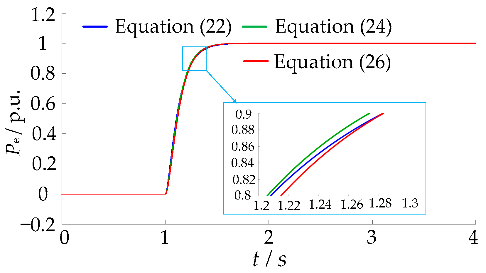
4. Simulation Comparison Results

The simulation test platform of a 100 kV·A GFVSG grid-connected system shown in Figure 1 is established by using the Matlab2016a/Simulink simulation software to verify the effectiveness of the proposed ERM-GFVSG in damping the active power dynamic oscillation. Meanwhile, comparison studies between the other damping control methods and the proposed ERM-GFVSG have also been implemented on the simulation test platform, including the GFVSG1 (D = 50.66 J/rad), the GFVSG2 (D = 335.16 J/rad), the active-power fractional differential correction (AFDC) [3], the ADFC [25], and the ADFF [25]. In order to achieve a fair comparison, a general rule is used to make each damping control method obtain the optimal dynamic performance in consideration of both the disturbances of the Pref and the ωg.
In this simulation, τ = 0.007 s, ωc = 142.86 rad/s, and Q = 0.5 are selected. The main parameters used in each damping control method are summarized in Table 3 and the other parameters are shown in Table 1.
Figure 9 shows the response waveforms of the Pe and the output frequency f for various damping control methods when the Pref steps from 20 kW to 60 kW at 4 s. Figure 9a illustrates the Pe response waveforms, whereas Figure 9b illustrates the f response waveforms. In Figure 9a, as the damping is only provided by the D (D = 50.66 J/rad) in the GFVSG1 (ξG = 0.16), the damping effect is limited and not enough to suppress the active power dynamic oscillation. On the other hand, there is no oscillation in the GFVSG2 (D = 335.16 J/rad), the AFDC-GFVSG, the ADFC-GFVSG, the ADFF-GFVSG, and the ERM-GFVSG. In terms of the dynamic response speed, the regulation time of the ERM-GFVSG and the ADFC-GFVSG is very similar, which is much longer than the other three damping control methods, and the regulation time of the GFVSG2 is slightly longer than that of the AFDC-GFVSG and the ADFF-GFVSG.
In Figure 9b, the response waveform of f in the GFVSG1 (ξG = 0.16) is obviously oscillatory when the Pref steps from 20 kW to 60 kW. Although the frequency overshoot exists in all damping control methods, the frequency overshoot of the ERM-GFVSG is smallest with a soft change slope at 4 s. Meanwhile, the frequency overshoot of the AFDC-GFVSG and the ADFF-GFVSG is similar with a severe change slope at 4 s, which is much larger than the other four damping control methods.
Figure 10 shows the response waveforms of the Pe and the f for various methods when the power grid frequency fg changes from 50 Hz to 49.95 Hz at 7 s.
Figure 10a illustrates the Pe response waveforms, whereas Figure 10b illustrates the f response waveforms. In Figure 10a, the damping ratio of the GFVSG1 (D = 50.66 J/rad) is small and not large enough to suppress the active power dynamic oscillation. Although the damping effect of the GFVSG2 (ξG = 1.07) is large enough to suppress the active power dynamic oscillation by increasing the D (D = 335.16 J/rad), a large active power steady state deviation ∆Pe0 (∆Pe0 = 28.1 kW) can be observed under the condition that the fg deviates from 50 Hz. On the other hand, there is no oscillation in the AFDC-GFVSG, the ADFC-GFVSG, the ADFF-GFVSG, and the ERM-GFVSG when the fg drops from 50 Hz to 49.95 Hz. It should be noted that in terms of the dynamic response speed, ERM-GFVSG has a relatively small active power overshoot, so its active power regulation time is slightly shorter than in the other damping control methods.
In Figure 10b, the response waveform of f in the GFVSG1 (ξG = 0.16) is obviously oscillatory when the fg changes from 50 Hz to 49.95 Hz. For the other five damping control methods, the slopes of the frequency changes at 7 s of the AFDC-GFVSG, the ADFC-GFVSG, the ADFF-GFVSG, and the ERM-GFVSG are all steeper than that of the GFVSG2. However, their frequency response time is much shorter than that of the GFVSG2. Moreover, the damping performance of the ERM-GFVSG is satisfactory under the disturbance of the fg change, as it has a slightly dynamic smaller frequency drop than that of the AFDC-GFVSG, the ADFC-GFVSG, or the ADFF-GFVSG, and the steady-state frequency drop of each damping method described above, including the GFVSG with D = 335.16, is 49.95 Hz.

5. Experimental Comparison Results

In order to further validate the feasibility of the proposed ERM-GFVSG control method, experimental tests were carried out on a microgrid experiment platform, as shown in Figure 11 [25]. A structure diagram and a photograph of the microgrid platform are shown in Figure 11a and 11b, respectively. Figure 11c presents the test process of a 100 kV·A GFVSG, the main parameters of which are given in Table 1 and Table 3. The 100 kV·A GFVSG was controlled by an independent DSP TMS320F28335, which implemented the various damping control methods, as discussed in the above sections.
Figure 12 shows the response waveforms of the Pe and the f for various damping control methods when the Pref steps from 20 kW to 60 kW. Figure 12a illustrates the Pe response waveforms, whereas Figure 12b illustrates the f response waveforms. In Figure 12a, the damping effect of the GFVSG1 (D = 50.66 J/rad) is limited and not enough to suppress the active power dynamic oscillation. However, there is no oscillation in the GFVSG2 (D = 335.16 J/rad), the AFDC-GFVSG, the ADFC-GFVSG, the ADFF-GFVSG, and the ERM-GFVSG, and the regulation time of the ERM-GFVSG and the ADFC-GFVSG is very similar, which is much longer than the other three damping control methods. The regulation time of the GFVSG2 is slightly longer than that of the AFDC-GFVSG and the ADFF-GFVSG, which is consistent with Figure 9a.
In Figure 12b, the response waveform of f in the GFVSG1 (ξG = 0.16) is obviously oscillatory when the Pref steps from 20 kW to 60 kW. Although the frequency overshoot exists in all damping control methods, the frequency overshoot of the ERM-GFVSG is smallest with a soft change slope, which can correspond to Figure 9b. However, the frequency overshoot of the AFDC-GFVSG and the ADFF-GFVSG is similar with a severe change slope, which is much larger than the other four damping control methods.
Figure 13 shows the response waveforms of the Pe and the f for various damping control methods when the fg drops from 50 Hz to 49.95 Hz. Figure 13a illustrates the Pe response waveforms, whereas Figure 13b illustrates the f response waveforms. In Figure 13a, the damping ratio of the GFVSG1 (D = 50.66 J/rad) is not large enough to suppress the active power dynamic oscillation. Although the GFVSG2 (ξG = 1.07) is able to suppress the active power dynamic oscillation by increasing the D (D = 335.16 J/rad), the ∆Pe0 = 28.3 kW can be observed when the fg deviates from 50 Hz in the steady state. And there is no oscillation in the AFDC-GFVSG, the ADFC-GFVSG, the ADFF-GFVSG, and the ERM-GFVSG when the fg changes from 50 Hz to 49.95 Hz. In terms of the dynamic response speed, the regulation time of the ERM-GFVSG is slightly smaller than the other five damping control methods, which is shown in Figure 10a.
In Figure 13b, the response waveform of f in the GFVSG1 (ξG = 0.16) is obviously oscillatory when the fg drops from 50 Hz to 49.95 Hz. The slopes of the frequency changes in the AFDC-GFVSG, the ADFC-GFVSG, the ADFF-GFVSG, and the ERM-GFVSG are all steeper than the GFVSG1 or the GFVSG2. However, their frequency response speed is much faster than the GFVSG1 or the GFVSG2. And the damping performance of the ERM-GFVSG is satisfactory considering the disturbance of the fg change, as it has a smaller frequency drop than that of the AFDC-GFVSG, the ADFC-GFVSG, or the ADFF-GFVSG, which is consistent with Figure 10b.

6. Conclusions

To solve the dynamic oscillation problems existing in the Pe and the ω of GFVSG under the two disturbances of the Pref step and the fg change, an active power dynamic oscillation damping method based on ERM for the GFVSG is proposed in this paper. Through the theoretical analysis, mathematical modeling, energy reshaping, parameter design, simulation, and experimental validations, the following conclusions are drawn:
(1) From the perspective of energy flow, the larger the J value of GFVSG, the larger the stored energy and the longer the system takes to consume the stored energy, so the regulation time of the system will be longer. Meanwhile, the larger the D value, the larger the consumed energy and the shorter the system takes to consume the dynamic oscillation energy, the stronger the ability to suppress the active power dynamic oscillation.
(2) Although the Pe and the ω of the AFDC-GFVSG, the ADFC-GFVSG, the ADFF-GFVSG, and the proposed ERM-GFVSG all have neither dynamic oscillation nor active power steady-state deviation under the two disturbances, the frequency overshoot of the ERM-GFVSG under the Pref step disturbance is the smallest at the expense of the Pe regulation time, and the Pe regulation time of the ERM-GFVSG under the fg step disturbance is the shortest. Therefore, in the practical application of the ERM-GFVSG, the parameters kb1 and kb2 of ERM-GFVSG need to be selected in a compromise to balance the relationship between the regulation time and the frequency overshoot.
It is worth pointing out that the ERM-GFVSG control method is proposed based on the closed-loop small signal control model of a GFVSG grid-connected system, so the applicability and effectiveness of the active power oscillation damping method based on the ERM in islanded microgrids with multiple GFVSGs still need to be further studied.

Author Contributions

Conceptualization, R.S. and C.L.; methodology, R.S.; validation, R.S. and C.L.; formal analysis, R.S.; investigation, R.S. and C.L.; writing—original draft preparation, R.S. and C.L.; writing—review and editing, Z.D. and G.Y.; supervision, G.Y.; project administration, R.S. and Z.D. All authors have read and agreed to the published version of the manuscript.

Funding

This research was funded by the Guangxi Natural Science Foundation of China under grant numbers 2020GXNSFBA297124 and 2021GXNSFAA220038, the Guangxi Key Research and Development Project of China under grant number 2021AB03043.

Data Availability Statement

Data are contained within the text and cited references.

Acknowledgments

This work was supported by the Automation Department of the College of Mechanical and Control Engineering at the Guilin University of Technology.

Conflicts of Interest

The authors declare no conflict of interest.

Nomenclature

Pref, Qref, u abc * Command of active power, reactive power, and output voltage
Pe, QeGrid-connected active power and grid-connected reactive power
J, DVirtual inertia and virtual damping
UdcDC source
Lf, CfAC filter inductor and AC filter capacitor
uabc, iabc, ugabcOutput voltage, output current, and power grid voltage
ω0, ωRated angular frequency and output angular frequency
XL, RLLine reactance and line resistance
δPower factor angle
kqPrimary voltage modulation coefficient
E0, ERated voltage amplitude and output voltage amplitude
Ug, ωgGrid voltage amplitude and gird angular frequency
ωn_G, ωn_ENatural oscillation angular frequency
ξG, ξEDamping ratio
kb1Active power feedback parameter
kb2Angular frequency feedback parameter
QQuality factor of the second-order LPF
ωc, ωc_ECut-off angular frequency
τFiltering time constant of the first-order LPF
γEPhase angle margin
f, fgOutput frequency and power grid frequency

Abbreviations

The following abbreviations are used in this manuscript:
GFVSGGrid-forming virtual synchronous generator
PECsPower electronic converters
TSGsTraditional synchronous generators
LPFLow-pass filter
PLLPhase locked loop
ERMEnergy reshaping mechanism
ERM-GFVSGGFVSG with the active power dynamic oscillation damping method based on ERM
CCVSCurrent controlled voltage source
VCCSVoltage controlled current source
AFDCActive-power fractional differential correction
ADFCActive-power differential feedback compensation
ADFFActive-power differential feedforward compensation
AFDC-GFVSGGFVSG with AFDC control algorithm
ADFC-GFVSGGFVSG with ADFC control algorithm
ADFF-GFVSGGFVSG with ADFF control algorithm

References

  1. Xu, H.Z.; Yu, C.Z.; Liu, C.; Wang, Q.L.; Zhang, X. An Improved Virtual Inertia Algorithm of Virtual Synchronous Generator. J. Mod. Power Syst. Clean Energy 2020, 8, 377–386. [Google Scholar] [CrossRef]
  2. Li, C.; Yang, Y.; Mijatovic, N.; Dragicevic, T. Frequency Stability Assessment of Grid-Forming VSG in Framework of MPME With Feedforward Decoupling Control Strategy. IEEE Trans. Ind. Electron. 2022, 69, 6903–6913. [Google Scholar] [CrossRef]
  3. Shi, R.L.; Yang, G.H.; Wang, G.B.; Lan, C.H.; Huang, J.; Wang, B. Grid-Connected Active Power Response Strategy of Energy Storage VSG Based on Active-power Fractional Differential Correction. Electr. Power Automation Equip. 2023, 1–9. [Google Scholar] [CrossRef]
  4. Chen, S.M.; Sun, Y.; Han, H.; Fu, S.Q.; Luo, S.H.; Shi, G.Z. A modified VSG control scheme with virtual resistance to enhance both small-signal stability and transient synchronization stability. IEEE Trans. Power Electron. 2023, 38, 6005–6014. [Google Scholar] [CrossRef]
  5. Chen, M.; Zhou, D.; Blaabjerg, F. Enhanced Transient Angle Stability Control of Grid-Forming Converter Based on Virtual Synchronous Generator. IEEE Trans. Ind. Electron. 2022, 69, 9133–9144. [Google Scholar] [CrossRef]
  6. Yang, M.; Wang, Y.; Xiao, X.; Li, Y. A Robust Damping Control for Virtual Synchronous Generators Based on Energy Reshaping. IEEE Trans. Energy Convers. 2023, 38, 2146–2159. [Google Scholar] [CrossRef]
  7. Alipoor, J.; Miura, Y.; Ise, T. Power System Stabilization Using Virtual Synchronous Generator with Alternating Moment of Inertia. IEEE J. Emerg. Sel. Top. Power Electron. 2015, 3, 451–458. [Google Scholar] [CrossRef]
  8. Thomas, V.; Kumaravel, S.; Ashok, S. Fuzzy Controller-Based Self-Adaptive Virtual Synchronous Machine for Microgrid Application. IEEE Trans. Energy Convers. 2021, 36, 2427–2437. [Google Scholar] [CrossRef]
  9. Ren, M.W.; Li, T.; Shi, K.; Xu, P.F.; Sun, Y.X. Coordinated Control Strategy of Virtual Synchronous Generator Based on Adaptive Moment of Inertia and Virtual Impedance. IEEE J. Emerg. Sel. Top. Cir. Syst. 2021, 11, 99–110. [Google Scholar] [CrossRef]
  10. Wang, Z.H.; Zhang, Y.; Cheng, L.; Li, G.Q. Improved Virtual Synchronization Control Strategy with Multi-Parameter Adaptive Collaboration. Power Syst. Technol. 2023, 47, 2403–2414. [Google Scholar]
  11. Huang, L.B.; Xin, H.H.; Yuan, H.; Wang, G.Z.; Ju, P. Damping Effect of Virtual Synchronous Machines Provided by a Dynamical Virtual Impedance. IEEE Trans. Energy Conver. 2021, 36, 570–573. [Google Scholar] [CrossRef]
  12. Zhang, Y.N.; Xie, Y.H.; Zhang, L.; Li, M.L. Transient Control Strategy of Virtual Synchronous Generator with Adaptive Regulation of Active Power Deviation. Electr. Mach. Control 2023. Available online: http://kns.cnki.net/kcms/detail/23.1408.TM.20230823.1802.002.html (accessed on 24 August 2023).
  13. Mo, O.; Arco, S.D.; Suul, J.A. Evaluation of Virtual Synchronous Machines with Dynamic or Quasi-Stationary Machine Models. IEEE Trans. Ind. Electron. 2017, 64, 5952–5962. [Google Scholar] [CrossRef]
  14. Fang, J.; Lin, P.; Li, H.; Yang, Y.; Tang, Y. An Improved Virtual Inertia Control for Three-Phase Voltage Source Converters Connected to a Weak Grid. IEEE Trans. Power Electron. 2019, 34, 8660–8670. [Google Scholar] [CrossRef]
  15. Dong, D.; Wen, B.; Boroyevich, D.; Mattavelli, P.; Xue, Y. Analysis of Phase-Locked Loop Low-Frequency Stability in Three-Phase Grid-Connected Power Converters Considering Impedance Interactions. IEEE Trans. Ind. Electron. 2015, 62, 310–321. [Google Scholar] [CrossRef]
  16. Huang, L.; Xin, H.; Wang, Z. Damping Low-Frequency Oscillations Through VSC-HVdc Stations Operated as Virtual Synchronous Machines. IEEE Trans. Power Electron. 2019, 34, 5803–5818. [Google Scholar] [CrossRef]
  17. Liu, J.; Miura, Y.; Bevrani, H.; Ise, T. A Unified Modeling Method of Virtual Synchronous Generator for Multi-Operation-Mode Analyses. IEEE J. Emerg. Sel. Top. Power Electron 2021, 9, 2394–2409. [Google Scholar] [CrossRef]
  18. Chen, M.; Zhou, D.; Blaabjerg, F. Active Power Oscillation Damping Based on Acceleration Control in Paralleled Virtual Synchronous Generators System. IEEE Trans. Power Electron. 2021, 36, 9501–9510. [Google Scholar] [CrossRef]
  19. Xiong, X.; Wu, C.; Cheng, P.; Blaabjerg, F. An Optimal Damping Design of Virtual Synchronous Generators for Transient Stability Enhancement. IEEE Trans. Power Electron. 2021, 36, 11026–11030. [Google Scholar] [CrossRef]
  20. Sun, P.; Yao, J.; Zhao, Y.; Fang, X.; Cao, J. Stability Assessment and Damping Optimization Control of Multiple Grid-connected Virtual Synchronous Generators. IEEE Trans. Energy Convers. 2021, 36, 3555–3567. [Google Scholar] [CrossRef]
  21. Baruwa, M.; Fazeli, M. Impact of Virtual Synchronous Machines on Low-Frequency Oscillations in Power Systems. IEEE Trans. Power Syst. 2021, 36, 1934–1946. [Google Scholar] [CrossRef]
  22. Yu, Y.; Chaudhary, S.K.; Tinajero, G.D.A.; Xu, L.; Abu Bakar, N.N.B.; Vasquez, J.C.; Guerrero, J.M. A Reference- Feedforward-Based Damping Method for Virtual Synchronous Generator Control. IEEE Trans. Power Electron. 2022, 37, 7566–7571. [Google Scholar] [CrossRef]
  23. Lan, Z.; Long, Y.; Zeng, J.H.; Tu, C.M.; Xiao, F. Transient Power Oscillation Suppression Strategy of Virtual Synchronous Generator Considering Overshoot. Autom. Electr. Power Syst. 2022, 46, 131–141. [Google Scholar]
  24. Li, M.X.; Yu, P.; Hu, W.H.; Wang, Y.; Shu, S.R.; Zhang, Z.Y.; Blaabjerg, F. Phase Feedforward Damping Control Method for Virtual Synchronous Generators. IEEE Trans. Power Electron. 2022, 37, 9790–9806. [Google Scholar] [CrossRef]
  25. Shi, R.L.; Zhang, Q.Y.; Wang, G.B.; Lan, C.H.; Huang, J.; Wang, B. Transient Damping Strategies to Improve Grid-Connected Active Response Performance of Energy Storage VSG. Electr. Power Autom. Equip. 2023, 1–11. [Google Scholar] [CrossRef]
  26. Semlyen, A. Analysis of Disturbance Propagation in Power Systems Based on a Homogeneoue Dynamic Model. IEEE Trans. Power Appar. Syst. 1974, PAS-93, 676–684. [Google Scholar] [CrossRef]
Figure 1. Circuit topology and control block diagram of GFVSG grid-connected system.
Energies 16 07723 g001
Figure 2. Equivalent power transmission model of GFVSG grid-connected system.
Energies 16 07723 g002
Figure 3. Closed-loop small signal control model of GFVSG grid-connected system.
Energies 16 07723 g003
Figure 4. Dynamic equivalent circuit model of GFVSG grid-connected system.
Energies 16 07723 g004
Figure 5. Dynamic equivalent circuit model of ERM-GFVSG grid-connected system.
Energies 16 07723 g005
Figure 6. Closed-loop small signal control model of ERM-GFVSG grid-connected system.
Energies 16 07723 g006
Figure 7. Comparison of the step responses of the G1_E(s) with different orders.
Energies 16 07723 g007
Figure 8. Comparison of the frequency response characteristics of GFVSG and ERM-GFVSG: (a) ΔPe(s)/ΔPref(s); (b) ΔPe(s)/Δωg(s); (c) Δω(s)/ΔPref(s); (d) Δω(s)/Δωg(s).
Energies 16 07723 g008
Figure 9. Comparative simulation results of various damping control methods when the Pref steps from 20 kW to 60 kW at 4 s: (a) the Pe response waveforms, (b) the f response waveforms.
Energies 16 07723 g009
Figure 10. Comparative simulation results of various damping control methods when the fg drops from 50 Hz to 49.95 Hz at 7 s: (a) the Pe response waveforms, (b) the f response waveforms.
Energies 16 07723 g010
Figure 11. Microgrid experiment platform: (a) structure diagram, (b) photograph, (c) a 100 kV·A GFVSG prototype.
Energies 16 07723 g011
Figure 12. Comparative experimental results of various damping control methods when the Pref steps from 20 kW to 60 kW: (a) the Pe response waveforms, (b) the f response waveforms.
Energies 16 07723 g012
Figure 13. Comparative experimental results of various damping control methods when the fg drops from 50 Hz to 49.95 Hz: (a) the Pe response waveforms, (b) the f response waveforms.
Energies 16 07723 g013
Table 1. The analogy relationships between the electromechanical and electromagnetic variables.
TypesVariables
Electromechanical1/K0ωPeδ
ElectromagneticLCuiΨ
Table 2. The main parameters of a 100 kV·A GFVSG.
SymbolParameterValue
E0Rated voltage amplitude311 V
UdcDC bus voltage700 V
ω0Rated angular frequency314.15 rad/s
JVirtual inertia8 kg·m2
kqPrimary voltage regulation coefficient1.4 × 10−4 V/var
DVirtual damping50.66 J/rad
LfFilter inductance50.6 mH
CfFilter capacitor270 uF
fsSampling frequency5 kHz
XLLine reactance0.15 Ω
Table 3. The main parameters of each damping control method.
MethodSymbolParameterValue
AFDC-GFVSGμFractional differential order0.8
ADFC-GFVSGKBDifferential feedback parameter0.08
ξBDamping ratio1.02
ADFF-GFVSGKFDifferential feedforward parameter0.08
ξFDamping ratio1.02
GFVSG1DVirtual damping50.66 J/rad
ξGDamping ratio0.16
GFVSG2DVirtual damping335.16 J/rad
ξGDamping ratio1.07
ERM-GFVSGkb1Active power feedback parameter0.12
Kb2Angular frequency feedback parameter200
ξEDamping ratio1.05
Disclaimer/Publisher’s Note: The statements, opinions and data contained in all publications are solely those of the individual author(s) and contributor(s) and not of MDPI and/or the editor(s). MDPI and/or the editor(s) disclaim responsibility for any injury to people or property resulting from any ideas, methods, instructions or products referred to in the content.

