
Easy and Scalable Syntheses of Li1.2Ni0.2Mn0.6O2

Abstract
:1. Introduction
2. Materials and Methods
3. Results and Discussion
4. Conclusions
Author Contributions
Funding
Data Availability Statement
Conflicts of Interest
References
- Nayak, P.K.; Erickson, E.M.; Schipper, F.; Penki, T.R.; Munichandraiah, N.; Adelhelm, P.; Sclar, H.; Amalraj, F.; Markovsky, B.; Aurbach, D. Review on challenges and recent advances in the electrochemical performance of high capacity Li- and Mn-rich cathode materials for Li-ion batteries. Adv. Energy Mater. 2018, 8, 1702397. [Google Scholar] [CrossRef]
- Lu, Z.H.; MacNeil, D.D.; Dahn, J.R. Layered cathode materials Li[NixLi(1/3-2x/3)Mn(2/3-x/3)]O2 for lithium-ion batteries. Electrochem. Solid. State Lett. 2001, 4, A191–A194. [Google Scholar] [CrossRef]
- Konishi, H.; Terada, S.; Okumura, T. Suppression of irreversible capacity for Li1.16Ni0.37Mn0.47O2 due to the chemical treatment with (NH4)2SO4 in lithium-ion batteries. J. Electroanal. Chem. 2019, 855, 113492. [Google Scholar] [CrossRef]
- Konishi, H.; Gunji, A.; Feng, X.; Furutsuki, S. Effect of transition metal composition on electrochemical performance of nickel-manganese-based lithium-rich layer-structured cathode materials in lithium-ion batteries. J. Solid. State Chem. 2017, 249, 80–86. [Google Scholar] [CrossRef]
- Wang, G.; Xie, J.; Cao, G.; Zhu, T.; Zhao, X.; Zhang, S. Electrochemical performance of 0.5Li2MnO3-0.5LiNi0.5Mn0.5O2 nanotubes prepared by a self-templating route. ECS Electrochem. Lett. 2013, 2, A98–A101. [Google Scholar] [CrossRef]
- Zhao, S.Q.; Guo, Z.Q.; Yan, K.; Wan, S.W.; He, F.R.; Sun, B.; Wang, G.X. Towards high-energy-density lithium-ion batteries: Strategies for developing high-capacity lithium-rich cathode materials. Energy Storage Mater. 2021, 34, 716–734. [Google Scholar] [CrossRef]
- Zheng, J.M.; Gu, M.; Xiao, J.; Zuo, P.J.; Wang, C.M.; Zhang, J.G. Corrosion/fragmentation of layered composite cathode and related capacity/voltage fading during cycling process. Nano Lett. 2013, 13, 3824–3830. [Google Scholar] [CrossRef] [PubMed]
- Chong, S.K.; Chen, Y.Z.; Yan, W.W.; Guo, S.W.; Tan, Q.; Wu, Y.F.; Jiang, T.; Liu, Y.N. Suppressing capacity fading and voltage decay of Li-rich layered cathode material by a surface nano-protective layer of CoF2 for lithium-ion batteries. J. Power Sources 2016, 332, 230–239. [Google Scholar] [CrossRef]
- Zhu, W.; Chong, S.K.; Sun, J.J.; Guo, S.W.; Tai, Z.G.; Wang, Y.J.; Liu, Y.N. The enhanced electrochemical performance of Li1.2Ni0.2Mn0.6O2 through coating MnF2 nano protective layer. Energy Technol. 2019, 7, 1702397. [Google Scholar] [CrossRef]
- Liu, Y.J.; Gao, Y.Y.; Wang, Q.L.; Dou, A.C. Influence of coated MnO2 content on the electrochemical performance of Li1.2Ni0.2Mn0.6O2 cathodes. Ionics 2014, 20, 825–831. [Google Scholar] [CrossRef]
- Mu, K.C.; Cao, Y.B.; Hu, G.R.; Du, K.; Yang, H.; Gan, Z.G.; Peng, Z.D. Enhanced electrochemical performance of Li-rich cathode Li1.2Ni0.2Mn0.6O2 by surface modification with WO3 for lithium-ion batteries. Electrochim. Acta 2018, 273, 88–97. [Google Scholar] [CrossRef]
- Zhao, Y.J.; Lv, Z.; Xu, T.; Li, J.X. SiO2 coated Li1.2Ni0.2Mn0.6O2 as cathode materials with rate performance, HF scavenging and thermal properties for Li-ion batteries. J. Alloys Compd. 2017, 715, 105–111. [Google Scholar] [CrossRef]
- Yan, P.F.; Zheng, J.M.; Zhang, X.F.; Xu, R.; Amine, K.; Xiao, J.; Zhang, J.G.; Wang, C.M. Atomic to nanoscale investigation of functionalities of an Al2O3 coating layer on a cathode for enhanced battery performance. Chem. Mater. 2016, 28, 857–863. [Google Scholar] [CrossRef]
- Liu, Y.J.; Wang, Q.L.; Wang, X.Q.; Wang, T.C.; Gao, Y.Y.; Su, M.R.; Dou, A.C. Improved electrochemical performance of Li1.2Ni0.2Mn0.6O2 cathode material with fast ionic conductor Li3VO4 coating. Ionics 2015, 21, 2725–2733. [Google Scholar] [CrossRef]
- Liu, Y.J.; Wang, Q.L.; Zhang, Z.Q.; Dou, A.C.; Pan, J.; Su, M.R. Investigation the electrochemical performance of layered cathode material Li1.2Ni0.2Mn0.6O2 coated with Li4Ti5O12. Adv. Powder Technol. 2016, 27, 1481–1487. [Google Scholar] [CrossRef]
- Zhang, L.L.; Chen, J.J.; Cheng, S.; Xiang, H.F. Enhanced electrochemical performances of Li1.2Ni0.2Mn0.6O2 cathode materials by coating LiAlO2 for lithium-ion batteries. Ceram. Int. 2016, 42, 1870–1878. [Google Scholar] [CrossRef]
- Sun, Y.; Zhang, X.; Cheng, J.; Guo, M.; Li, X.; Wang, C.; Sun, L.; Yan, J. Surface modification with lithium-ion conductor Li3PO4 to enhance the electrochemical performance of lithium-rich layered Li1.2Ni0.2Mn0.6O2. Ionics 2023, 29, 2141–2152. [Google Scholar] [CrossRef]
- Liu, Y.; Liu, D.; Zhang, Z.; Zheng, S.; Wan, H.; Dou, A.C.; Su, M. Investigation of the structural and electrochemical performance of Li1.2Ni0.2Mn0.6O2 with Cr doping. Ionics 2017, 24, 2251–2259. [Google Scholar] [CrossRef]
- Huang, Z.M.; Li, X.H.; Liang, Y.H.; He, Z.J. Structural and electrochemical characterization of Mg-doped Li1.2[Mn0.54Ni0.13Co0.13]O2 cathode material for lithium ion batteries. Solid. State Ion. 2015, 282, 88–94. [Google Scholar] [CrossRef]
- He, Z.J.; Wang, Z.X.; Chen, H.; Huang, Z.M. Electrochemical performance of zirconium doped lithium rich layered Li1.2Mn0.54Ni0.13Co0.13O2 oxide with porous hollow structure. J. Power Sources 2015, 299, 334–341. [Google Scholar] [CrossRef]
- Liu, H.; Tao, L.; Wang, W.; Zhang, B.; Su, M. Effects of raw materials on the electrochemical performance of Na-doped Li-rich cathode materials Li[Li0.2Ni0.2Mn0.6]O2. Ionics 2018, 25, 959–968. [Google Scholar] [CrossRef]
- Yang, M.C.; Hu, B.; Geng, F.S.; Li, C.; Lou, X.B.; Hu, B.W. Mitigating voltage decay in high-capacity Li1.2Ni0.2Mn0.6O2 cathode material by surface K+ doping. Electrochim. Acta 2018, 291, 278–286. [Google Scholar] [CrossRef]
- Li, X.N.; Cao, Z.X.; Yue, H.Y.; Wang, Q.X.; Zhang, H.S.; Yang, S.T. Tuning primary particle growth of Li1.2Ni0.2Mn0.6O2 by Nd-modification for improving the electrochemical performance of lithium-ion batteries. ACS Sustain. Chem. Eng. 2019, 7, 5946–5952. [Google Scholar] [CrossRef]
- He, T.; Chen, L.; Su, Y.; Lu, Y.; Bao, L.; Chen, G.; Zhang, Q.; Chen, S.; Wu, F. The effects of alkali metal ions with different ionic radii substituting in Li sites on the electrochemical properties of Ni-Rich cathode materials. J. Power Sources 2019, 441, 227195. [Google Scholar] [CrossRef]
- Weber, D.; Tripković, D.; Kretschmer, K.; Bianchini, M.; Brezesinski, T. Surface Modification Strategies for Improving the Cycling. Performance of Ni-Rich. Cathode Materials. Eur. J. Inorg. Chem. 2020, 33, 3117–3130. [Google Scholar] [CrossRef]
- Cai, Z.; Wang, S.; Zhu, H.; Tang, X.; Ma, Y.; Yu, D.Y.W.; Zhang, S.; Song, G.; Yang, W.; Xu, Y.; et al. Improvement of stability and capacity of Co-free, Li-rich layered oxide Li1.2Ni0.2Mn0.6O2 cathode material through defect control. J. Colloid. Interface Sci. Part B 2023, 630, 281–289. [Google Scholar] [CrossRef] [PubMed]
- Xiang, Y.; Yin, Z.; Zhang, Y.; Li, X. Effects of synthesis conditions on the structural and electrochemical properties of the Li-rich material Li[Li0.2Ni0.17Co0.16Mn0.47]O2 via the solid-state method. Electrochim. Acta 2013, 91, 214–218. [Google Scholar] [CrossRef]
- Liu, J.; Chen, L.; Hou, M.; Wang, F.; Che, R.; Xia, Y. General synthesis of xLi2MnO3·(1−x)LiMn1/3Ni1/3Co1/3O2 nanomaterials by a molten-salt method: Towards a high capacity and high power cathode for rechargeable lithium batteries. J. Mater. Chem. 2012, 22, 25380–25387. [Google Scholar] [CrossRef]
- Fu, F.; Deng, Y.P.; Shen, C.H.; Xu, G.L.; Peng, X.X.; Wang, Q.; Xu, Y.F.; Fang, J.C.; Huang, L.; Sun, S.G. A hierarchical micro/nanostructured 0.5Li2MnO3·0.5LiMn0.4Ni0.3Co0.3O2 material synthesized by solvothermal route as high-rate cathode of lithium-ion battery. Electrochem. Commun. 2014, 44, 54–58. [Google Scholar] [CrossRef]
- Zheng, F.; Ou, X.; Pan, Q.; Xiong, X.; Yang, C.; Liu, M. The effect of composite organic acid (citric acid & tartaric acid) on microstructure and electrochemical properties of Li1.2Mn0.54Ni0.13Co0.13O2 Li-rich layered oxides. J. Power Sources 2017, 346, 31–39. [Google Scholar]
- Zhong, Z.; Ye, N.; Wang, H.; Ma, Z. Low temperature combustion synthesis and performance of spherical 0.5Li2Mn-LiNi0.5Mn0.5O2 cathode material for Li-ion batteries. Chem. Eng. J. 2011, 175, 579–584. [Google Scholar] [CrossRef]
- Liu, Y.; Liu, D.; Wu, H.H.; Fan, X.; Dou, A.; Zhang, Q.; Su, M. Improved cycling stability of Na-doped cathode materials Li1.2Ni0.2Mn0.6O2 via a facile synthesis. ACS Sustain. Chem. Eng. 2018, 6, 13045–13055. [Google Scholar] [CrossRef]
- Yang, P.; Li, H.; Wei, X.; Zhang, S.; Xing, Y. Structure tuned Li1.2Mn0.6Ni0.2O2 with low cation mixing and Ni segregation as high-performance cathode materials for Li-ion batteries. Electrochim. Acta 2018, 271, 276–283. [Google Scholar] [CrossRef]
- Zhao, T.; Gao, X.; Wei, Z.; Guo, K.; Wu, F.; Li, L.; Chen, R. Three-dimensional Li1.2Ni0.2Mn0.6O2 cathode materials synthesized by a novel hydrothermal method for lithium-ion batteries. J. Alloy. Compd. 2018, 757, 16–23. [Google Scholar] [CrossRef]
- Hao, R.; Liang, J.; Yang, Z.; Liang, C.; Cuan, X.; Gao, A.; Chen, H. Synthesis and Investigation of the nanocrystalline Li1.2Ni0.2Mn0.6O2 cathodes for Li-ion batteries by using ultrasonic/microwave-assisted co-precipitation method with different ultrasonic time. J. S. China Norm. Univ. 2017, 49, 6–10. [Google Scholar]
- Li, L.; Wang, L.; Zhang, X.; Xue, Q.; Wei, L.; Wu, F.; Chen, R. 3D reticular Li1.2Ni0.2Mn0.6O2 cathode material for lithium-ion batteries. ACS Appl. Mater. Interfaces 2017, 9, 1516–1523. [Google Scholar] [CrossRef] [PubMed]
- Wang, H.; Li, X.; Zhou, Q.; Ming, H.; Adkins, J.; Jin, L.; Jia, Z.; Fu, Y.; Zheng, J. Diversified Li1.2Ni0.2Mn0.6O2 nanoparticles from birnessite towards application specificity and enhancement in lithium-ion batteries. J. Alloy. Compd. 2014, 604, 217–225. [Google Scholar] [CrossRef]
- Lim, J.H.; Bang, H.; Lee, K.S.; Amine, K.; Sun, Y.K. Electrochemical characterization of Li2MnO3– Li[Ni1/3Co1/3Mn1/3]O2–LiNiO2 cathode synthesized via co-precipitation for lithium secondary batteries. J. Power Sources 2009, 189, 571–575. [Google Scholar] [CrossRef]
- Hu, S.; Pillai, A.S.; Liang, G.; Pang, W.K.; Wang, H.; Li, Q.; Guo, Z. Li-rich layered oxides and their practical challenges: Recent progress and perspectives. Electrochem. Energy Rev. 2019, 2, 277–311. [Google Scholar] [CrossRef]
- Jarvis, K.; Wang, C.C.; Manthiram, A.; Ferreira, P.J. The Role of Composition in the Atomic Structure, Oxygen Loss, and Capacity of Layered Li–Mn–Ni Oxide Cathodes. J. Mater. Chem. A 2014, 2, 1353–1362. [Google Scholar] [CrossRef]
- Pechini, M.P. Method of Preparing Lead and Alkaline Earth Titanates and Niobates and Coating Method Using the Same to Form a Capacitor. US Patent No. 3,330,697, 11 July 1967. [Google Scholar]
- Rapulenyane, N.; Ferg, E.; Luo, H. High-performance Li1.2Mn0.6Ni0.2O2 cathode materials prepared through a facile one-pot co-precipitation process for lithium-ion batteries. J. Alloys Compd. 2018, 762, 272–281. [Google Scholar] [CrossRef]
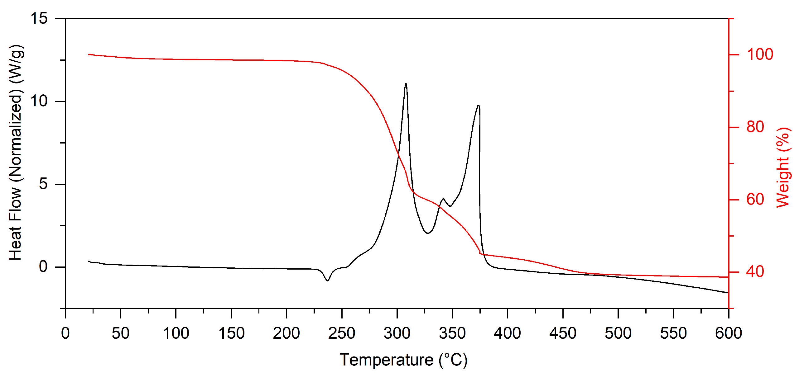
- Afzal, M.; Butt, P.K.; Ahrnad, H. Kinetics of thermal decomposition of metal acetates. J. Therm. Anal. 1991, 37, 1015–1102. [Google Scholar] [CrossRef]
- Tobón-Zapata, G.E.; Ferrer, E.G.; Etcheverry, S.B.; Baran, E.J. Thermal behaviour of pharmacology active lithium compounds. J. Therm. Anal. Cal. 2000, 61, 29–35. [Google Scholar] [CrossRef]
- Hussein, G.A.M.; Nohman, A.K.H.; Attyia, K.M.A. Characterization of the decomposition course of nickel acetate tetrahydrate in air. J. Therm. Anal. 1994, 42, 1155–1165. [Google Scholar] [CrossRef]
- Abdel-Ghany, A.; Hashem, A.M.; Mauger, A.; Julien, C.M. Lithium-Rich Cobalt-Free Manganese-Based Layered Cathode Materials for Li-Ion Batteries: Suppressing the Voltage Fading. Energies 2020, 13, 3487. [Google Scholar] [CrossRef]
- Takeda, Y.; Akagi, J.; Edagawa, A.; Inagaki, M.; Naka, S. A preparation and polymorphic relations of sodium iron oxide (NaFeO2). Mater. Res. Bull. 1980, 15, 1167–1172. [Google Scholar] [CrossRef]
- Song, X.; Huang, H.; Zhong, W. Sucrose-assisted synthesis of layered lithium-rich oxide Li[Li0.2Mn0.56Ni0.16Co0.08]O2 as a cathode of lithium-ion battery. Crystals 2019, 9, 436. [Google Scholar] [CrossRef]
- Hamad, K.I.; Xing, Y. Stabilizing Li-rich NMC materials by using precursor salts with acetate and nitrate anions for Li-ion batteries. Batteries 2019, 5, 69. [Google Scholar] [CrossRef]
- Lu, Z.; Beaulieu, L.Y.; Donaberger, R.A.; Thomas, R.A.; Dahn, J.R. Synthesis, structure, and electrochemical behavior of Li[NixLi1/3–2x/3Mn2/3–x/3]O2. J. Electrochem. Soc. 2002, 149, A778. [Google Scholar] [CrossRef]
- Ohzuku, T.; Ueda, A.; Nagayama, M. Electrochemistry and structural chemistry of LiNiO2 (R3m) for 4 volt secondary lithium cells. J. Electrochem. Soc. 1993, 140, 1862–1870. [Google Scholar] [CrossRef]
- He, X.; Wang, J.; Wang, L.; Li, J. Nano-crystalline Li1.2Mn0.6Ni0.2O2 prepared via amorphous complex precursor and its electrochemical performances as cathode material for lithium-ion batteries. Materials 2016, 9, 661. [Google Scholar] [CrossRef] [PubMed]
- Zhang, H.; Liu, H.; Piper, L.F.J.; Whittingham, M.S.; Zhou, G. Oxygen Loss in Layered Oxide Cathodes for Li-Ion Batteries: Mechanisms, Effects, and Mitigation. Chem. Rev. 2022, 122, 5641–5681. [Google Scholar] [CrossRef] [PubMed]
- Parekh, M.-H.; Palanisamy, M.; Pol, V.G. Reserve lithium-ion batteries: Deciphering in situ lithiation of lithium-ion free vanadium pentoxide cathode with graphitic anode. Carbon 2023, 203, 561–570. [Google Scholar] [CrossRef]
- Xie, H.X.; Cui, J.X.; Yao, Z.; Ding, X.K.; Zhang, Z.H.; Luo, D.; Lin, Z. Revealing the role of spinel phase on Li-rich layered oxides: A review. Chem. Eng. J. 2022, 427, 131978. [Google Scholar] [CrossRef]
- Boulineau, A.; Simonin, L.; Colin, J.F.; Bourbon, C.; Patoux, S. First Evidence of Manganese-Nickel Segregation and Densification upon Cycling in Li-Rich Layered Oxides for Lithium Batteries. Nano Lett. 2013, 13, 3857–3863. [Google Scholar] [CrossRef] [PubMed]
- Kim, D.; Sandi, G.; Croy, J.R.; Gallagher, K.G.; Kang, S.H.; Lee, E.; Slater, M.D.; Johnson, C.S.; Thackeray, M.M. Composite ‘layered-layered-spinel’ cathode structures for lithium-ion batteries. J. Electrochem. Soc. 2013, 160, A31–A38. [Google Scholar] [CrossRef]
- Yang, Z.; Zheng, C.; Wei, Z.; Zhong, J.; Liu, H.; Feng, J.; Li, J.; Kang, F. Multi-dimensional correlation of layered Li-rich Mn-based cathode materials. Energy Mater. 2022, 2, 200006. [Google Scholar] [CrossRef]
- Li, X.; Xu, Y.; Wang, C. Suppression of Jahn-Teller distortion of spinel LiMn2O4 cathode. J. Alloys. Compd. 2009, 479, 310–313. [Google Scholar] [CrossRef]
- Wang, C.C.; Lin, Y.C.; Chou, P.H. Mitigation of layer to spinel conversion of a lithium-rich layered oxide cathode by substitution of Al in a lithium-ion battery. RSC Adv. 2015, 5, 68919–68928. [Google Scholar] [CrossRef]
- Wang, Y.; Yang, Z.; Qian, Y.; Gu, L.; Zhou, H. New Insights into Improving Rate Performance of Lithium-Rich Cathode Material. Adv. Mater. 2015, 27, 3915–3920. [Google Scholar] [CrossRef]


| Starting Compound | LiAc·2H2O | Li2CO3 | Mn(Ac) 2·4H2O | Mn(Ac)2·4H2O | Ni(Ac)2·4H2O | Total |
|---|---|---|---|---|---|---|
| Final compound | Li2CO3 | Li2O | MnO2 | Mn2O3 | Ni2O3 | |
| Weight/g | 3.060 | - | 2.451 | 1.225 | 1.244 | 7.980 |
| Mol | 0.030 | 0.015 | 0.010 | 0.005 | 0.005 | 0.065 |
| Anhydrous weight/g | 1.980 | 1.110 | 1.729 | 0.865 | 0.883 | 5.458 |
| Weight final/g | 1.110 | 0.450 | 0.869 | 0.395 | 0.413 | 2.128 |
| Weight loss/% * | 15.94 | 12.09 | 15.76 | 8.61 | 8.61 | 61.02 |
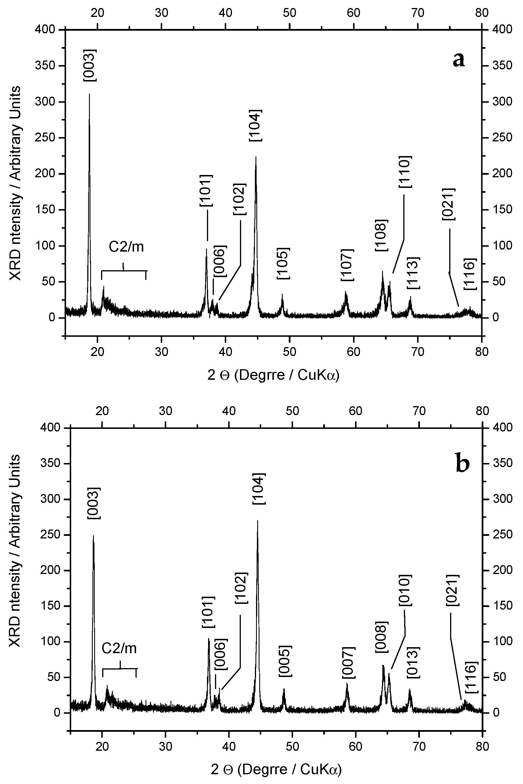
| Sample | I [003] | I [104] | I [006] | I [102] | I [101] | R1 = I [003]/I [104] | R2 = (I [006] + I [102])/I [101] |
|---|---|---|---|---|---|---|---|
| SS | 311 | 224 | 17 | 17 | 87 | 1.39 | 0.39 |
| SG | 243 | 270 | 17 | 34 | 97 | 0.9 | 0.52 |
Disclaimer/Publisher’s Note: The statements, opinions and data contained in all publications are solely those of the individual author(s) and contributor(s) and not of MDPI and/or the editor(s). MDPI and/or the editor(s) disclaim responsibility for any injury to people or property resulting from any ideas, methods, instructions or products referred to in the content. |
© 2023 by the authors. Licensee MDPI, Basel, Switzerland. This article is an open access article distributed under the terms and conditions of the Creative Commons Attribution (CC BY) license (https://creativecommons.org/licenses/by/4.0/).
Share and Cite
Prosini, P.P.; Aurora, A.; Della Seta, L.; Paoletti, C. Easy and Scalable Syntheses of Li1.2Ni0.2Mn0.6O2. Energies 2023, 16, 7674. https://doi.org/10.3390/en16227674
Prosini PP, Aurora A, Della Seta L, Paoletti C. Easy and Scalable Syntheses of Li1.2Ni0.2Mn0.6O2. Energies. 2023; 16(22):7674. https://doi.org/10.3390/en16227674
Chicago/Turabian StyleProsini, Pier Paolo, Annalisa Aurora, Livia Della Seta, and Claudia Paoletti. 2023. "Easy and Scalable Syntheses of Li1.2Ni0.2Mn0.6O2" Energies 16, no. 22: 7674. https://doi.org/10.3390/en16227674