Article

Smoothing Intermittent Output Power in Grid-Connected Doubly Fed Induction Generator Wind Turbines with Li-Ion Batteries

by
Henok Ayele Behabtu
1,2,*,
Majid Vafaeipour
1,
Abraham Alem Kebede
2,
Maitane Berecibar
1,
Joeri Van Mierlo
1,
Kinde Anlay Fante
2,
Maarten Messagie
1 and
Thierry Coosemans
1
1
Electric Vehicle and Energy Research Group (EVERGI), Mobility, Logistics and Automotive Technology Research Centre (MOBI), Department of Electrical Engineering and Energy Technology, Vrije Universiteit Brussel, 1050 Brussels, Belgium
2
Faculty of Electrical and Computer Engineering, Jimma Institute of Technology, Jimma University, Jimma P.O. Box 378, Ethiopia
*
Author to whom correspondence should be addressed.
Energies 2023, 16(22), 7637; https://doi.org/10.3390/en16227637
Submission received: 20 October 2023 / Revised: 9 November 2023 / Accepted: 14 November 2023 / Published: 17 November 2023
(This article belongs to the Topic Smart Energy Systems, 2nd Edition)

Abstract

:
Wind energy is an increasingly important renewable resource in today’s global energy landscape. However, it faces challenges due to the unpredictable nature of wind speeds, resulting in intermittent power generation. This intermittency can disrupt power grid stability when integrating doubly fed induction generators (DFIGs). To address this challenge, we propose integrating a Li-ion battery energy storage system (BESS) with the direct current (DC) link of grid-connected DFIGs to mitigate power fluctuations caused by variable wind speed conditions. Our approach entails meticulous battery modeling, sizing, and control methods, all tailored to match the required output power of DFIG wind turbines. To demonstrate how well our Li-ion battery solution works, we have developed a MATLAB/Simulink R2022a version model. This model enables us to compare situations with and without the Li-ion battery in various operating conditions, including steady-state and dynamic transient scenarios. We also designed a buck–boost bidirectional DC-DC converter controlled by a proportional integral controller for battery charging and discharging. The battery actively monitors the DC-link voltage of the DFIG wind turbine and dynamically adjusts its stored energy in response to the voltage level. Thus, DFIG wind turbines consistently generate 1.5 MW of active power, operating with a highly efficient power factor of 1.0, indicating there is no reactive power produced. Our simulation results confirm that Li-ion batteries effectively mitigate power fluctuations in grid-connected DFIG wind turbines. As a result, Li-ion batteries enhance grid power stability and quality by absorbing or releasing power to compensate for variations in wind energy production.

1. Introduction

Worldwide, the capacity for generating renewable energy is expanding at a rapid pace [1]. This growth can be attributed to the cost-effectiveness and the lack of or limited carbon emission effects of renewable energy sources (RESs). Likewise, wind energy sources (WESs) are rapidly advancing within RESs, and their operational, control, and maintenance aspects have reached a level of maturity that is comparable to conventional power plants [2,3]. However, ensuring a consistent and reliable power supply for utilities becomes challenging when the grid relies on WESs, which are intermittent and somewhat unpredictable [4].
Variable-speed wind turbine generators (WTGs), such as the doubly fed induction generator (DFIG), are commonly employed in large-scale wind power plants (WPPs) [5]. Currently, DFIG wind turbines hold a significant share, accounting for 50% of the wind energy market due to their cost-effectiveness and compact size, making them a preferred choice [6]. DFIG wind turbines offer several advantages, including flexible active and reactive power control, lower converter costs compared to permanent magnet synchronous generators (PMSGs), reduced power losses, a lightweight design, and high efficiency [2,5].
However, integrating DFIG wind turbines with the grid comes with specific challenges. These include output power fluctuations during faults and variations due to changing wind speeds [7,8]. Additionally, it introduces complexities like deviations in system frequency and voltage, impacting grid stability and power quality. This makes matching supply and demand challenging, and planning power production is also complicated because of DFIG’s variable output power [9,10,11].
To address these challenges, energy storage technologies (ESTs) have emerged as a promising solution for mitigating the output power fluctuations of DFIGs [12,13,14]. Energy storage systems (ESSs) store excess energy during periods of high wind speed and release it to the power grid when the wind speed decreases [11,13,15]. Thus, the integration of ESSs with DFIGs makes it possible to smooth the generated power as wind speeds vary [16].
When selecting the right ESTs for specific applications, several factors are considered. These factors include energy and power density, lifetime, cost, efficiency, technology maturity, response time, self-discharge time, power rating, discharge time, and environmental impact [17]. There is a range of ESTs utilized in the renewable energy sector, including flywheel energy storage (FES) [18,19], pumped hydro energy storage (PHES) [20], supercapacitor energy storage (SCES) [21,22], superconductive magnetic energy storage (SMES) [23,24], compressed air energy storage (CAES) [25,26], and battery energy storage systems (BESSs) [27,28,29].
Among the available ESTs, BESSs stand out because of their quick response, high energy efficiency, wide power range, extended discharge capacity, and efficient cycling [17,30]. BESSs have versatile applications, including capacity firming, frequency regulation, load leveling, peak shaving, improving power quality, and providing spinning reserves in power systems [31]. The authors of [32] conducted a comparative analysis of traditional battery systems and flow battery ESSs within the context of RES applications. In a separate study, researchers in [33] developed an asymmetric encoder–decoder model to predict the lifetime of Zn-ion batteries.
Several studies have investigated power smoothing methods for WESs using ESTs, such as the implementation of SMES for stability improvement of WESs [24], the combined use of electrical double layer capacitors and BESSs for mitigation of wind power fluctuation [34], SCES for DFIG wind turbine power smoothing [22], and the application of flywheel and BESSs in solar and WESs [18]. Ultracapacitors and zinc bromide batteries have also been explored for mitigating the fluctuating output power of WESs [9]. BESSs have been applied to mitigate frequency variations and compensate for energy generation losses under fault conditions [29]. The dynamic modeling of batteries, including the Warburg circuit-based model [4], has been performed, and the performance of these models has been evaluated by connecting solar and WESs to the grid system [4]. Furthermore, dynamic models have also been created for DFIG wind turbines and Li-ion batteries [35].
In reference [36], the researchers investigated the sub-synchronous resonance effect in DFIG-based WPPs and proposed mitigation techniques employing BESS-based damping controllers. Meanwhile, a novel dynamic flywheel system designed for DFIG wind turbines, emphasizing coordinated control of kinetic energy and mechanical torque was introduced in [37]. It also explored a control strategy involving an energy capacitor system for fixed-speed wind turbines with squirrel cage induction generators.
Different control mechanisms for DFIGs and ESTs have been considered, such as model predictive control (MPC) for smoothing the intermittency and variability of WPPs using a BESS [11]. A dynamic model for a DFIG wind turbine and a multi-state feedback (MSF) current controller strategy for rotor side converter (RSC) and grid side converter (GSC) controllers were developed in [6]. Sliding mode control (SMC) has been suggested for smoothing the power fluctuations of grid-connected DFIG wind turbines due to its fast calculations and easy installation advantages. Additionally, artificial intelligence methods like fuzzy logic (FL) and artificial neural networks (ANNs) were used to enhance the performance of SMC and reduce undesirable buzzing effects [38]. A widely used technique, known as vector control or field-oriented control (FOC), was employed to achieve precise control of a DFIG system. This approach separates the control of active and reactive power components, allowing independent regulation of torque and flux [39]. Furthermore, simulation models have been developed for grid-connected wind farms and BESSs [13].
In [40], a comprehensive investigation into the fault ride-through capabilities (FRTC) of PMSGs was undertaken. This review not only investigated the theoretical basis but also distinguished the unique features of various FRTC approaches and illustrates their respective strengths and limitations. Furthermore, the study involves simulating five scenarios of DC-link voltage without grid connection, using MATLAB/Simulink R2022a version, to assess the effectiveness of these FRTC methods. Moving forward, researchers in reference [41] introduced an innovative control methodology based on the super-twisting algorithm (STA), which effectively regulates both reactive and active output power in DFIG wind turbines. In reference [42], a new intelligent control approach for hybrid PV–wind–batteries was proposed, employing neuro-fuzzy direct power control (NF-DPC) to enhance system performance and ensure high-quality current generation. Researchers in reference [43] explore the application of a BESS to smooth the power output from wind turbines, utilizing a fuzzy logic power control strategy. Lastly, reference [44] presents a coordinated control scheme for WTGs and BESSs that not only provides fast frequency regulation (FFR) to the AC system but also extends the battery’s cycle life.
Reference [45] introduced the concept of feedforward frequency deviation control (FFDC) for DFIG-based wind turbines, aimed at enhancing their inertial response. The study encompassed the development of an inertia model, an analysis of control loop influences on inertia characteristics, and the proposition of FFDC. By incorporating frequency deviation feedforward into the phase-locked loop (PLL), FFDC effectively boosted inertial response without compromising the PLL’s dynamic performance under standard conditions. In reference [46], the authors presented an energy-efficient scheduling strategy for distribution networks, emphasizing source–load–storage groups. They harnessed advanced forecasting techniques and fine-tuned their approach using the improved sparrow search algorithm (ISSA) and its multi-objective counterpart (MOSSA). Through simulations, they demonstrated the efficacy of their approach in optimizing energy distribution systems featuring distributed generation. Reference [47] addressed wind speed forecasting improvement by introducing a hidden Markov model (HMM) with fuzzy C-means clustering and kernel density estimation (KDE). The HMM enhanced accuracy and corrected wind speed predictions, surpassing benchmark results in case studies.
In reference [48], the authors explored the impact of asymmetrical grid impedance on weak grid stability, particularly in the context of grid-connected inverters (GCIs). Their comprehensive model accounted for asymmetrical networks and helped identify critical parameters, drawing upon eigenvalue analysis. Their research indicated that heightened grid impedance asymmetry reduced the stability region for key parameters. Validation through simulations and experiments confirmed the model’s efficacy and theoretical findings. In reference [49], a low-pass virtual filter (VF) was introduced for wind energy conversion systems to mitigate power output fluctuations. The authors also established a stability-constrained coefficient to ensure WTG stability. Through simulations and experiments, they verified the VF’s proficiency in reducing power fluctuations and the coefficient’s pivotal role in sustaining system stability.
Numerous research studies have investigated the use of ESTs to mitigate power fluctuations in DFIG wind turbines, as evident in the existing literature. However, it is of paramount importance to understand that the selection of ESTs, their size, associated costs, and how they are configured can significantly impact their suitability and effectiveness for specific applications.
In this context, Li-ion batteries have attracted attention due to their unique characteristics, including rapid response time, high power and energy density, high cycle efficiency, compact size, low self-discharge rate, and minimal environmental impact [17]. Thus, this paper focuses on modeling and analyzing the role of Li-ion batteries in mitigating power fluctuations in grid-connected DFIG wind turbines. The study includes a comprehensive model covering wind turbines, DFIG, batteries, and their controller. We also address the sizing of Li-ion batteries and the design and control of a buck–boost bidirectional DC-DC converter for battery charging and discharging. We employ a MATLAB/Simulink model R2022a version to assess how Li-ion batteries influence the performance of grid-connected DFIG wind turbines. We analyze their impact in both steady-state and dynamic transient conditions, considering different wind speeds. This study aims to provide insights relevant to grid system design and operation.
The structure of this paper is as follows: In Section 2, we investigate the system configurations of integrating a BESS with grid-connected DFIG wind turbines. This section focuses on creating mathematical models for essential components, such as the wind turbine, DFIG, and power converters, using equivalent circuit representations. Moving on to Section 3, we provide a comprehensive exploration of the modeling, sizing, and control methods for Li-ion batteries. We offer detailed guidelines for determining the optimal battery size for grid-connected DFIG wind turbines and introduce a control technique for Li-ion battery charging and discharging using a bidirectional buck–boost DC-DC converter. In Section 4, we outline our system modeling and simulation methodology. We use a MATLAB/Simulink R2022a version model to simulate grid-connected DFIG wind turbines. We study their performance with and without Li-ion batteries in both steady-state and dynamic transient conditions, considering variable wind speeds. Lastly, in Section 5, we draw our conclusions based on the insights collected from the simulation results presented in Section 4. This paper offers a comprehensive examination of the integration of Li-ion batteries with DFIG wind turbines, with implications for grid system design and operation.

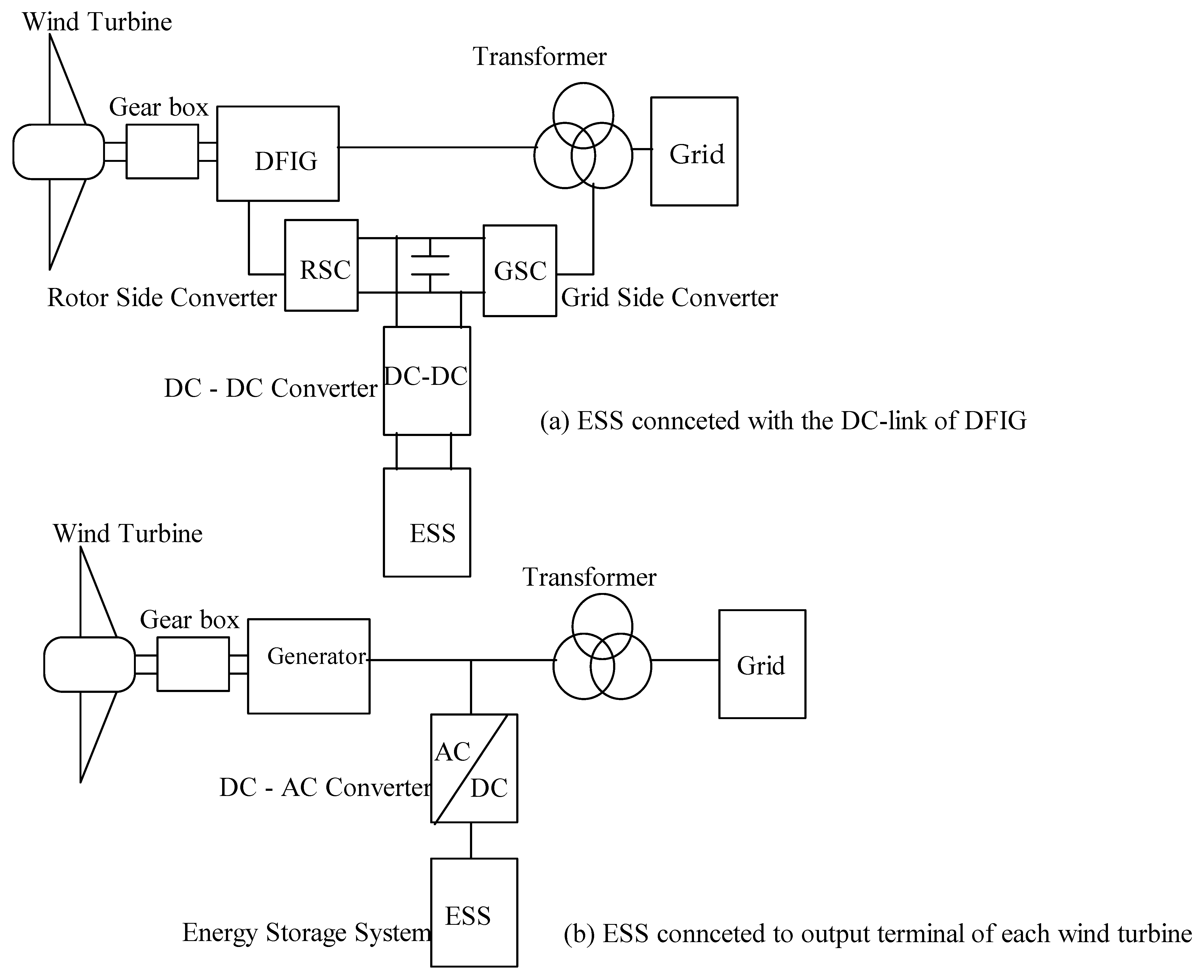
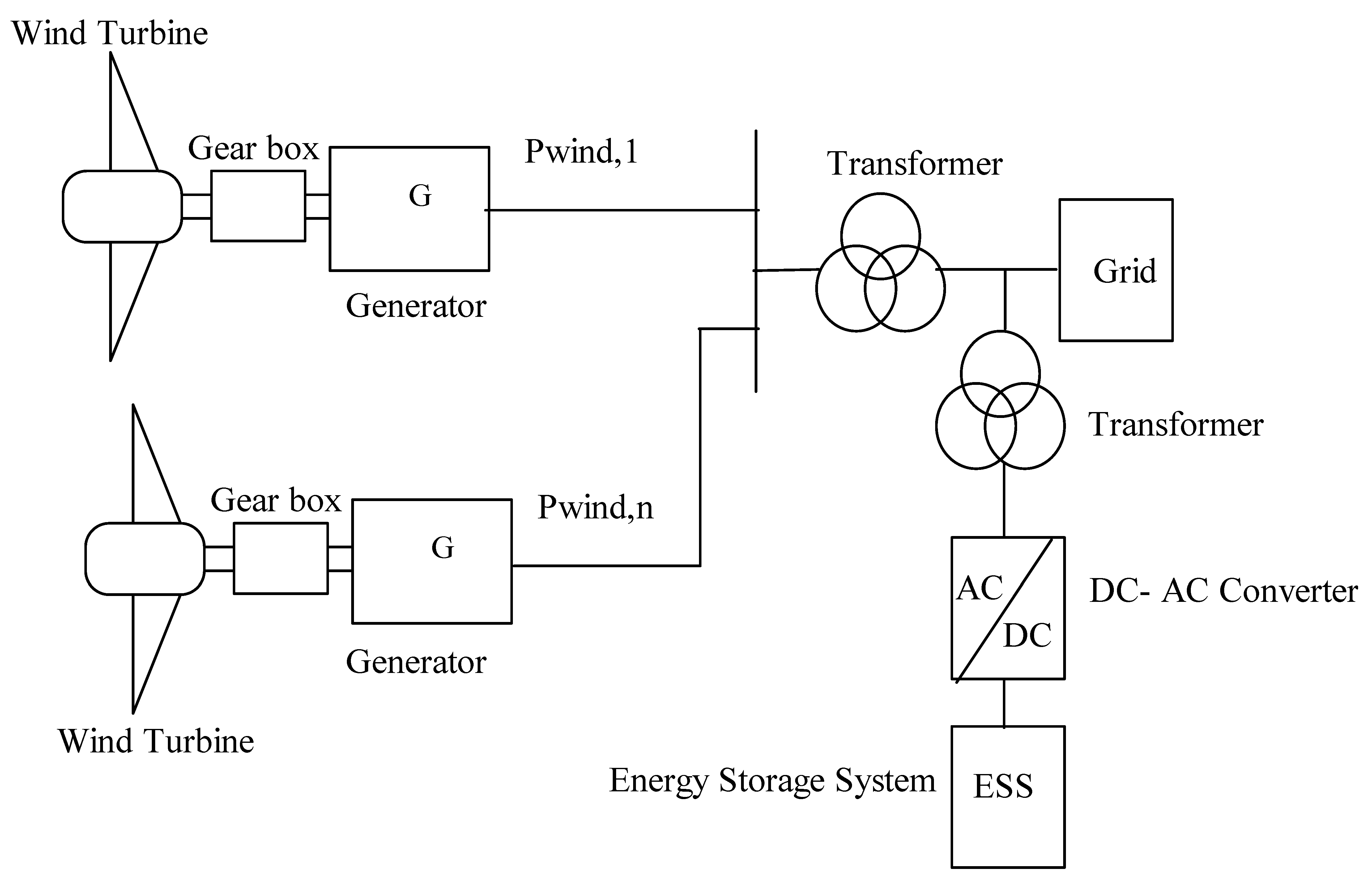
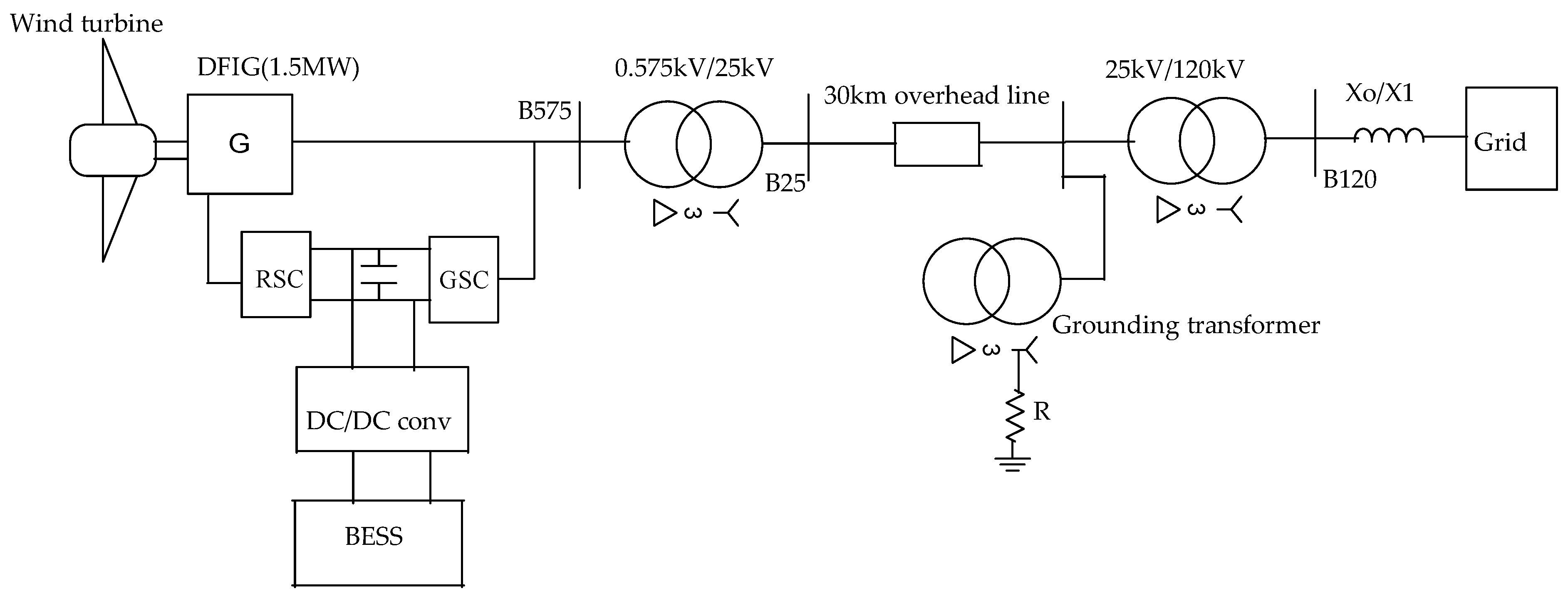
2. System Configuration of a Battery Energy Storage System with DFIG Wind Turbines

When WTGs are connected to the grid, they can utilize an ESS to stabilize their power production, thereby reducing the impact of fluctuations caused by changes in wind speed. An ESS can be connected to a WTG in two main configuration modes: distributed and centralized [50]. Figure 1 and Figure 2 provide schematic diagrams for these two configuration modes. Figure 1 shows that an ESS is connected either to the output terminal of each WTG or directly to the DC-link of a DFIG or PMSG wind turbine.
Integrating an ESS into the DC-link of a WTG offers the advantage of utilizing the existing grid-side converter (GSC), thereby reducing initial investment costs. However, this approach requires the reconfiguration of the GSC’s control mode, leading to increased control complexity for the WTG [50,51]. Furthermore, as shown in Figure 1b, integrating an ESS at the output terminal of a WTG requires the connection of an extra DC-AC power converter. However, this approach maintains the structure and control mode of the generators without alterations [50].
Similarly, a grid-connected WTG employs the centralized configuration shown in Figure 2. In this setup, an independent ESS is connected to the exit bus of the WPP. Centralized configuration modes are used to control the output power of entire grid-connected WPPs [50]. This configuration is particularly attractive from both technical and economic perspectives [52]. However, it is worth noting that because the ESS is not distributed, any malfunction in the power converter or the ESS can impact the entire system. Thus, our study aims to explore the role of Li-ion batteries in a grid-connected DFIG with a distributed configuration setup, which offers advantages over centralized configurations of ESSs integrated with WTGs.
Figure 1a illustrates the proposed topology for investigating the integration of Li-ion batteries with the DC-link of a grid-connected DFIG wind turbine. To perform the study, it is crucial to understand the parameters of turbines, generators, power converters, and batteries. The proposed setup consists of four main sections:
  • A mechanical wind turbine that can operate at varying wind speeds.
  • An induction generator with externally accessible rotor terminals.
  • A bidirectional voltage source converter (VSC) ensures power flow control in varying wind conditions.
  • An ESS connected to the DC-link.
Usually, the DFIG’s rotor terminal is connected to the back-to-back converters, while the stator terminal is directly linked to the grid. To reduce the converter’s voltage rating, it connects to the grid through a transformer. These back-to-back VSC converters often have lower ratings (about 25–30% of the machine’s rating) [3,7,53]. The rotor side converter (RSC), connected to the rotor winding, converts the generator’s low-frequency alternating current (AC) into DC, which is then converted back to AC by the GSC after stabilization with a DC-link capacitor.
As illustrated in Figure 1a, a bidirectional DC-DC converter connects the ESS to the DC-link, allowing the battery to charge and discharge as needed. The active power, which is generated or consumed by both the battery and the DFIG rotor winding, is subsequently directed to or consumed by the GSC via the DC-link. From the GSC, this power is fed into the grid.
In the following subsections, we will present the mathematical models for the main components of the system depicted in Figure 1a. This includes the wind turbine, DFIG, and power converter. These models are developed based on their equivalent circuit representations. Our primary goal is to investigate the overall performance of the entire system and optimize wind power generation for smooth integration with the electrical grid. To achieve this, we will simplify the modeling of individual components to ensure that the system can be effectively simulated within reasonable timeframes using simulation software.

2.1. Modeling of the DFIG Wind Turbine

The development of a model for a DFIG wind turbine involves using mathematical equations to describe its various components and how they work together. We utilize software like MATLAB/Simulink R2022a version for this modeling and simulation process. Our model is built using the SimPowerSystems® R2022a [54] framework, which has been customized to ensure effective control of the DFIG upon its integration with Li-ion batteries. The DFIG system can be divided into two subsystems: the mechanical system and the electrical system. Detailed descriptions of the modeling process for these subsystems will be provided in the subsequent subsections.

2.1.1. Mechanical System Model
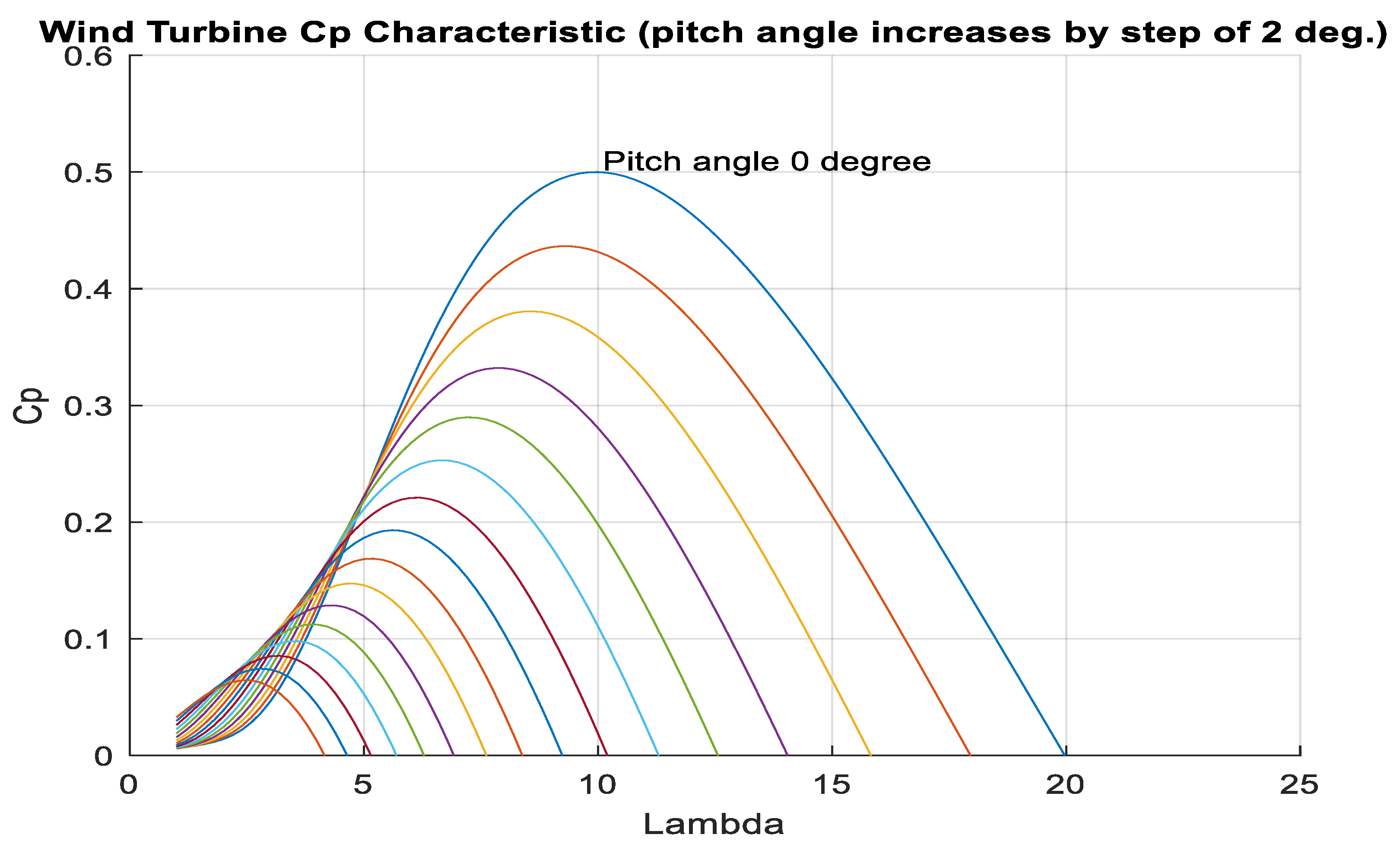
The mechanical system model for a DFIG wind turbine helps us understand how the turbine responds and enables us to enhance its overall performance. The mechanical system of a DFIG wind turbine includes the aerodynamic rotor and the drive train system component [55].

Aerodynamic Rotor

A wind turbine is a complex system, and its output relies on optimizing several parameters. Equation (1) can be used to represent the overall power of a wind turbine ( P w i n d ) [56].
P w i n d = 1 2 ρ A r v 3
where ρ is air density in kg/ m 3 , A r is the area swept by the rotor in m 2 , and v is wind speed in m/s. Equation (2) can be used to describe the mechanical power ( P w t ) generated by a wind turbine [55,56,57,58,59]:
P w t = 1 2   ρ π R 2 C p ( λ ,   β )   v 3
where R is the turbine blade radius in m, and C p is the power coefficient expressed as a function of the tip speed ratio ( λ ) and blade pitch angle ( β ).
From Equation (2), the power generated by a wind turbine is directly proportional to the cube of the wind speed. Consequently, as the wind speed fluctuates, the resulting output power from the WTGs also varies, leading to fluctuations in their output power.
Moreover, C p represents the performance or power coefficient, which is essentially a measure of how efficiently a wind turbine converts the available wind energy into electrical power. The maximum possible efficiency, as determined by the Betz limit, is 59.3% [60]. This coefficient, C p , also plays a crucial role in determining the maximum power output of a wind turbine and is influenced by factors such as λ and β. The parameter λ is defined by Equation (3), as described in references [4,57].
  λ = s p e e d   o f   t h e   r o t o r   b l a d e s p e e d   o f   o n   c o m i n g   a i r = ω o R v
where ω o   is the rotational speed in rad/s.
Equation (4) defines an approximation of C p based on λ and β [57].
C p   λ , β = 0.5176     116 α 0.4 β 5 e 21 / α + 0.0068   λ 1 α = 1 λ   +   0.08 β 0.035 β 3   +   1
where α is the intermediate variable to obtain the C p by using λ and β.
Adjusting the C p values allows for the control of power extraction in the wind turbine. Figure 3 illustrates the relationship between C p   and λ for different pitch angle values. The output power of a DFIG wind turbine is influenced by λ, C p , β, and wind speed. Wind speed variations affect the available wind power while adjusting the pitch angle can optimize aerodynamic performance. To maximize power production and efficiency, finding the right balance among these factors is crucial.
The aerodynamics system converts the wind’s kinetic energy into mechanical energy, which is represented as torque and speed [60]. We can calculate the mechanical torque produced by the wind turbine by dividing the mechanical power by the wind turbine’s rotational speed [55,57].
T w t = P w t ω w t
where T w t is the mechanical torque, P w t is the mechanical power, and ω w t is the wind turbine’s rotational speed.
This torque is transmitted from the drive train to the generator through a gearbox, which increases the rotational speed to match the requirements of the DFIG rotor.

Drive Train

The widely recognized two-mass dynamic model is a common approach when modeling a drive train [55]. This model consists of two masses: the aerodynamic rotor and the generator rotor, which are connected by springs with defined stiffness and damping factors. The Equations (6)–(8) represent this model [55]:
T w t T m e c = J w t · d ω w t d t
T w t = D d t · ω w t ω r + K d t · ω w t ω r d t  
T e T m e c ω r · F = J r · d ω r d t
where K d t and D d t stand for the stiffness and damping of the mechanical coupling, ω r represents the angular velocity of the generator, F is the coefficient representing viscous friction from the generator shaft, J r refers to the inertia of the aerodynamic rotor, T m e c   is the mechanical torque coming from the generator shaft, T e   represents the electrical torque produced by the generator, and T w t represents the mechanical torque generated by the aerodynamic rotor shaft.

2.1.2. Electrical System Model
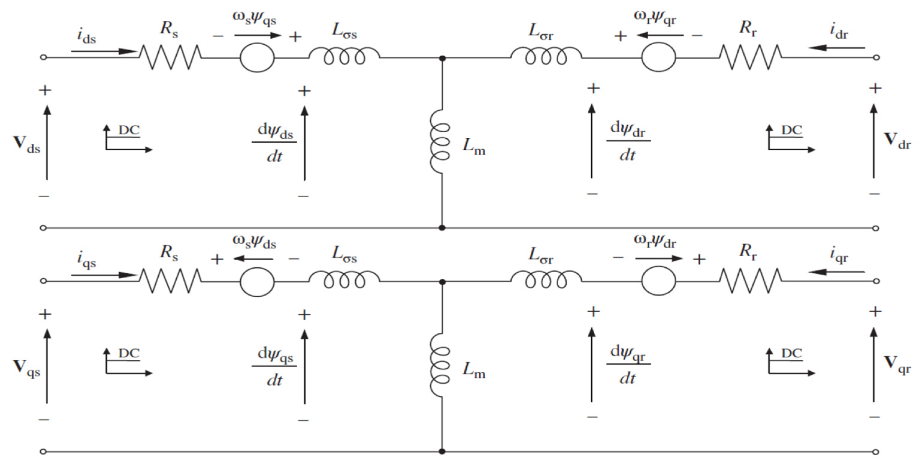
The electrical system model of a DFIG wind turbine incorporates the stator, rotor, and power electronic converters. This model allows for the analysis of the generator’s operation, stability, and control strategies. The following subsections will elaborate on the modeling of the electrical system, including the DFIG and power electronic converters.

DFIG Model

To comprehensively analyze the properties and impacts of grid-connected DFIG systems, it is essential to employ a simplified mathematical model for the machine. The direct and quadrature (dq) model of DFIG proves to be highly advantageous for system analysis and control. Figure 4 illustrates the equivalent circuit diagram of the DFIG [61], which is derived by applying Kirchhoff’s rules to analogous circuits in the ABC reference frame. The model is further transformed into the dq (or synchronous) reference frame using a Park transformation, enabling more efficient analysis and control.
We modeled the DFIG wind turbine by employing mathematical equations that describe crucial electrical parameters. These parameters include stator voltage, rotor voltage, flux linkage at both stator and rotor sides, electromagnetic torque, as well as active and reactive power at both stator and rotor converter sides. The total active and reactive output power extracted from the DFIG wind turbine can be mathematically expressed through a series of equations (specifically, Equations (9)–(17)), as provided in [27,55,59,61,62,63]. These equations serve as valuable tools for comprehensively understanding the behavior of grid-connected DFIG wind turbines.
Stator voltage equation:
V d s = i d s R s ω s Ψ q s + d Ψ d s d t     V q s = i q s R s + ω s Ψ d s + d Ψ q s d t    
Rotor voltage equation:
V d r = i d r R r ω r Ψ q r + d Ψ d r d t V q r = i q r R r + ω r Ψ d r + d Ψ q r d t    
Stator flux linkage equation:
Ψ d s = L m i d r + L s i d s   Ψ q s = L m i q r + L s i q r  
Rotor flux linkage equation:
Ψ d r = L m i d s + L r i d r Ψ q r = L m i q s + L r i q r
where L s , L r , and L m are the stator, rotor, and mutual inductances, respectively.
And,
L s = L σ s + L m
L r = L σ r + L m
where L σ s   and L σ r are the self-inductances of the stator and the rotor, respectively.
Generator electromechanical torque equation:
T e = 1.5 × p × Ψ d s i q s Ψ q s i d s
where p denotes the number of pair poles.
Active and reactive power equation at the rotor side:
P r   = 1.5 V d r i d r + V q r i q r Q r   = 1.5 V q r i d r V d r i q r
Active and reactive power equation at stator side:
P s   = 1.5 V d s i d s + V q s i q s   Q s = 1.5 V q s i d s V d s i q s
Equation (18) provides a representation of the total active and reactive power generated by a DFIG wind turbine. The combination of power from both the stator and rotor constitutes the overall output power of a DFIG wind turbine.
P T o t a l = P s   + P r   Q T o t a l = Q s   + Q r
where V s , i s , and Ψ s stand for stator voltage, current, and flux, respectively; V r , i r , and Ψ r   represent rotor voltage, current, and flux, respectively; ω s and ω r   denote the angular velocity of the stator and rotor, respectively; and ‘d’ and ‘q’ are used to indicate the d and q axes, respectively.

DFIG’s Power Converter

The power converter system in a DFIG wind turbine is a crucial component that includes the GSC, RSC, and DC-link. This system plays a vital role in controlling power flow, ensuring system stability, and enabling variable-speed operation. To achieve this, the converters employ pulse width modulation (PWM) techniques along with advanced control algorithms [55]. By carefully adjusting the switching patterns of power electronic components like insulated gate bipolar transistors (IGBTs) or metal oxide silicon field effect transistors (MOSFETs) within the converters, they can generate the desired voltage and current waveforms necessary for efficient operation and integration with the grid.
The GSC plays a critical role in controlling the power flow between the electrical grid and the wind turbine. Its primary responsibility is to maintain synchronization and stability by regulating the voltage and frequency on the grid side. It achieves this by controlling the exchange of active and reactive power with the DFIG [55].
On the other hand, the RSC takes charge of regulating the rotor currents, enabling variable-speed operation, and enhancing the control capabilities of the DFIG system [55]. Importantly, the RSC provides independent control of the rotor currents, effectively separating the variables on the rotor side from those on the grid side. This decoupling capability is advantageous as it allows precise control of the active and reactive power exchanged between the rotor and the grid.
In addition, a common DC-link connects the GSC and RSC. This DC-link serves as an energy storage element, acting as a buffer between the two converters. Its main role is to maintain the desired voltage level on both sides and balance the power flow between the grid and the rotor. For a detailed model and control of the battery connected to the DC-link, Section 3 offers a comprehensive analysis of the bidirectional DC-DC battery power converter and its associated controller.

3. Modeling, Sizing, and Control of Battery Energy Storage Systems

This section focuses on three key aspects: the modeling, sizing, and control of the Li-ion battery connected to the DFIG’s DC-link through a bidirectional DC-DC power converter. In the subsequent section, we will provide the details of the modeling, sizing, and control of the batteries. This exploration is essential for gaining a clear understanding of how these batteries effectively manage energy within the DFIG wind turbine system, thereby optimizing its performance.

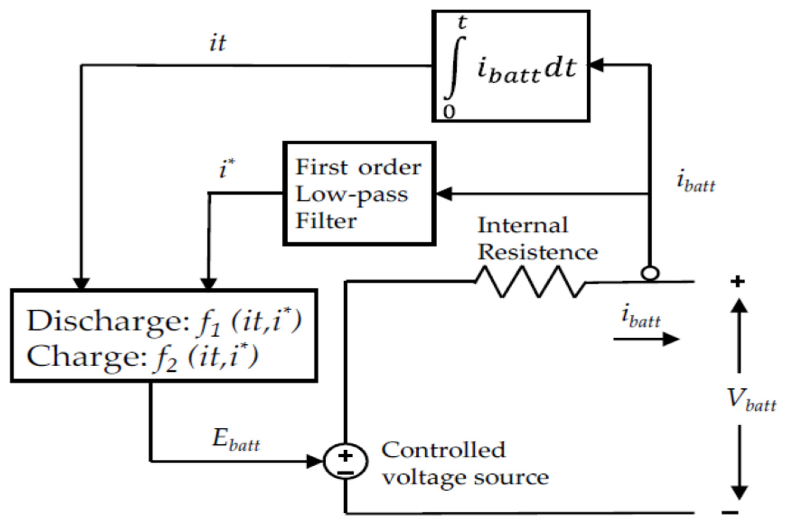
3.1. Battery Modeling

A BESS is a widely adopted solution for integrating RESs into the grid. The concept involves using a battery to store excess energy generated by renewables when demand is low and then releasing this stored energy when demand is high. This helps maintain a steady and stable supply of electricity to meet fluctuating grid requirements effectively.
In large-scale grid applications, batteries are typically represented as battery packs. Therefore, precise modeling and simulation methods are of utmost importance for studying the behavior, longevity, efficiency, performance, and management of these storage units. It becomes critical to make accurate forecasts and assessments of parameters like state of charge (SoC), state of health (SoH), depth of discharge (DoD), temperature, and currents to effectively control the batteries for specific applications [64,65].
Thus, optimizing battery utilization and creating effective energy systems requires a thorough understanding of battery behavior and the ability to forecast its performance. To accomplish this, researchers and engineers frequently use simulations and battery models.
Battery modeling covers a range of methodologies suited to various applications and precision needs. These methods cover electrical, electrochemical, thermal, mechanical, and interdisciplinary systems [65]. Electrical battery modeling falls into three categories: electrical circuit models (ECM), analytical models, and frequency-domain battery models [65]. These modeling techniques differ in complexity. For example, electrochemical battery models are highly complicated and time-consuming, involving a system of interconnected, time-varying, nonlinear differential equations [66]. On the other hand, ECM offers a faster and less computationally intensive approach, making it efficient for simulations, although it may not capture as many complicated details of battery performance as electrochemical models [65].
In battery studies, researchers employ various models to represent Li-ion batteries using equivalent circuits. These models, including Rint, RC, Partnership for a New Generation of Vehicles (PNGV), Thevenin, and second-order battery models, have been discussed in references [65,67]. Among these options, the Thevenin model stands out for its ability to provide a reasonable trade-off between computational efficiency and accuracy, as highlighted in reference [65]. This study employs generic Li-ion battery models created using MATLAB/Simulink R2022a version. The model and its internal block diagram can be accessed within the MATLAB/Simulink R2022a version environment. Figure 5 shows a simplified schematic diagram of the Li-ion battery model.
A generic battery model uses mathematical representations to simplify the complex electrochemical reactions and electrical characteristics within a battery. This model summarizes the complex equations and internal details of the battery, allowing us to study how the battery performs in different charging and discharging situations. Additionally, it helps us understand how external factors such as temperature, aging, and the load placed on the battery influence its operation.
The battery model is flexible, accommodating the most common rechargeable battery types like lead–acid (Pb-A), lithium-ion (Li-ion), nickel–cadmium (NiCd), and nickel–metal hydride (NiMH). To use this model correctly, the user needs to specify the battery type and provide other relevant details such as nominal voltage, rated capacity, SoC, etc. These parameter values can typically be found in the battery’s data sheets.
In this study, we performed in-depth modeling and simulation of Li-ion batteries for application in DFIG wind turbine grid integration. The Li-ion battery model, including both charging and discharging conditions, is described by Equations (19) and (20) [68].
Discharge model for i * > 0 :
f 1 i t , i * , i = E o K × Q Q i t × i * K × Q Q i t × i t + A × e x p B × i t
Charge mode for i * < 0:
f 2 i t , i * , i = E o K × Q i t + 0.1 Q × i * K × Q Q i t × i t + A × e x p B × i t
where i— represents the battery current in amperes (A), i * stands for low-frequency current dynamics in amperes, E o — stands for the constant voltage in Volts (V), and K—refers to the polarization constant, which can also be seen as polarization resistance, measured in Ohms (Ω); Q denotes the maximum battery capacity in ampere-hours (Ah), A represents the exponential voltage in Volts (V), and B corresponds to the exponential capacity measured in ampere-hours (Ah−1).
Moreover, the longevity or lifespan of a battery depends on several fundamental battery parameters, particularly the SoC, SoH, and DoD. The following subsections present an in-depth exploration of these parameters and their significant impacts on battery performance and longevity.

3.1.1. State of Charge

Charging Li-ion batteries beyond their capacity or discharging them excessively can shorten their lifespan and result in higher expenses [69]. To maximize system efficiency, extend battery life, and guarantee safe operation in diverse applications like electric vehicles (EVs), renewable energy grid integration, and building integration, it is essential to precisely calculate the SoC as a percentage for these batteries [70].
SoC is a crucial measure of the available power or capacity within a battery. It represents the current level of charge in the battery relative to its maximum capacity and is often expressed as a percentage, ranging from 0% (total discharge) to 100% (fully charged). SoC plays a vital role in optimizing battery efficiency and provides valuable information about the battery’s energy status.
Mathematically, SoC is defined as the ratio of the remaining capacity ( Q p r e s e n t ) to the nominal capacity of the cell ( Q n o m i n a l ) and it can be expressed as follows [70]:
S o C ( % ) = Q p r e s e n t Q n o m i n a l
In this context, capacity (Q) is usually measured in units of ampere-hours (Ah) or milliampere-hours (mAh). The SoC of a battery can also be represented in relation to the battery current using Equation (22) [71]:
S o C = 100 1 1 Q   0 t i t d t
where I t is the battery current (A), and Q is the maximum battery capacity (Ah).
SoC plays a significant role in determining how well a battery performs in grid applications. Thus, monitoring and managing a battery’s SoC are essential to maximize its performance, efficiency, and lifespan.

3.1.2. State of Health

SoH is a vital measure for determining a battery’s remaining functional lifespan and its overall performance. It provides insights into the battery’s ability to deliver its specified capacity and operate as intended. Additionally, SoH reflects the gradual degradation or reduced functionality that occurs over time due to factors like usage, aging, environmental conditions, cycling, and various stressors [72].
The SoH is calculated by dividing the battery’s current capacity by its initial capacity, as shown in Equation (23) [64]. As the battery ages, its capacity gradually decreases.
S o H = 100 × C m e a s u r e d C i n t i a l
where C m e a s u r e d is measured as available discharge capacity (Ah); and C i n t i a l   is initially available discharge capacity (Ah). SoH aids in predicting the battery’s remaining capacity and expected lifespan, facilitating improved system planning, scheduling of maintenance activities, and the optimal utilization of an ESS.

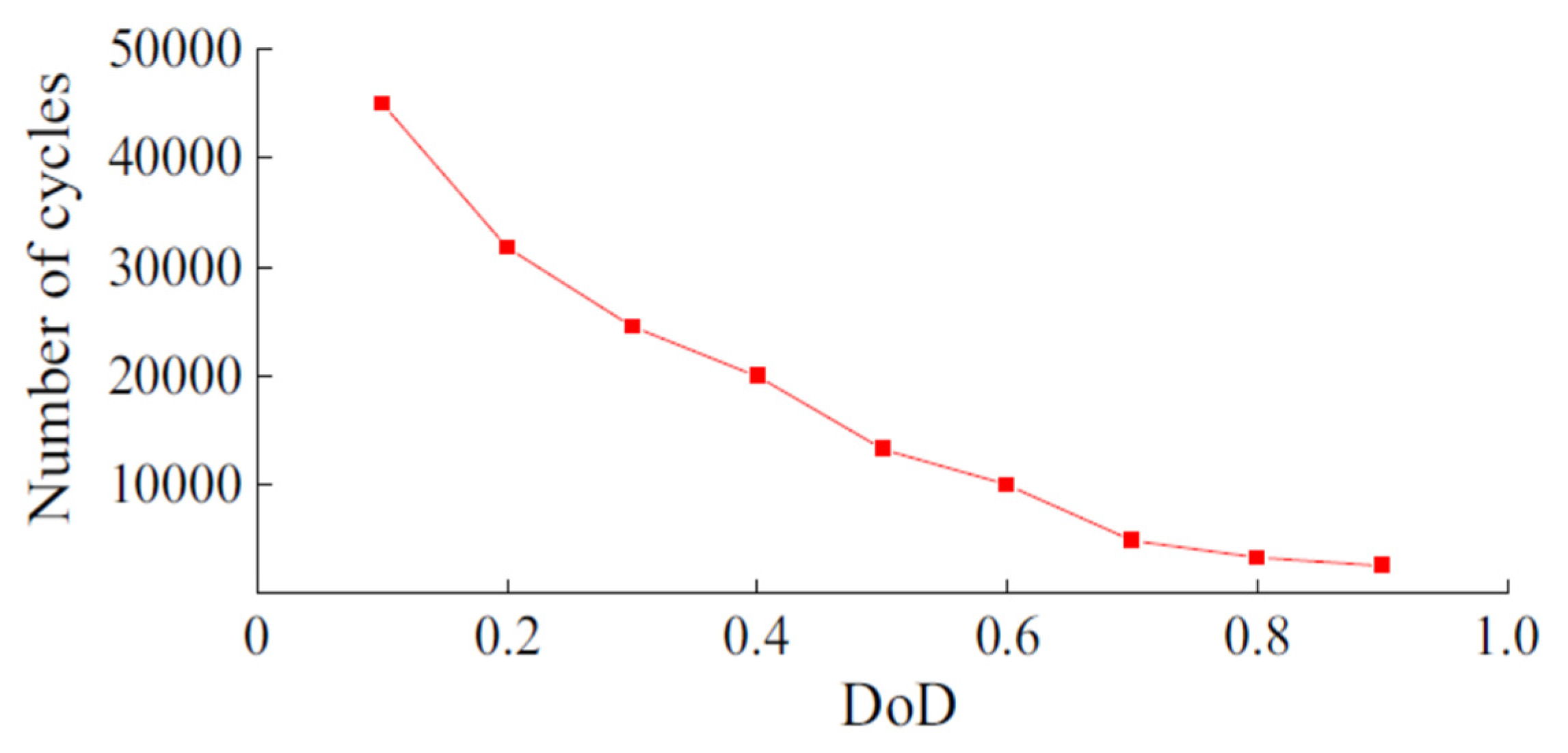
3.1.3. Depth of Discharge

In battery terminology, the DoD is a crucial concept. It indicates the fraction of a battery’s total capacity that has been used during a specific cycle or operation. Essentially, it represents how much of the battery’s energy has been utilized as a percentage of its maximum capacity.
SoC indicates the battery’s charge level as a percentage of its full capacity, as previously discussed in Section 3.1.1. The DoD, which is the numerical complement of SoC, can be expressed as follows [68]:
DoD = 100% − SoC
Thus, DoD is used to evaluate the battery’s SoC and calculate its remaining energy capacity.
To ensure a battery’s proper functioning and maintenance, monitoring and management of the DoD is essential. Allowing a battery to reach a high DoD level before recharging can have both positive and negative consequences. On the positive side, it enables greater energy utilization and increases the battery’s effective capacity. However, deep cycling can lead to a shorter battery lifespan, reduced overall efficiency over time, and increased stress on the battery.
Figure 6 illustrates that as the DoD range becomes larger, the battery’s overall cycle life tends to decrease. Different types of batteries, depending on their chemical makeup, have specific limitations when it comes to DoD. For instance, Li-ion batteries can handle deeper discharges without significant damage. To maximize both performance and the battery’s lifespan, it is generally recommended not to discharge it to its maximum DoD.
Battery operators and battery management systems often provide guidelines customized to the battery type and its intended application. These guidelines help regulate the DoD, ensuring the battery is used optimally. By managing the DoD carefully, one can estimate how much energy remains in the battery and prevent situations where it gets discharged excessively, leading to potential harm, shorter lifespan, or even irreversible damage to the battery.

3.2. Battery Sizing

The cost of a battery used for DFIG power smoothing is directly linked to its size. Accurate sizing of the battery is vital because it directly influences the cost and can have a significant impact on how efficiently and reliably both the DFIG and the grid operate. Therefore, ensuring the correct battery size for grid-connected DFIG power smoothing is a top priority.
Determining the right size for the battery used in DFIG power smoothing depends on various factors. These factors include the DFIG’s power rating, the energy capacity of the storage device, the duration needed for power smoothing, as well as the upper and lower limits of power supply and grid frequency range [51].
The steps required in sizing a battery for DFIG output power smoothing are as follows [8,51]:
(1)
Determine the DFIG’s power rating: Finding out the DFIG’s power rating is the first step in sizing a battery for DFIG output power smoothing. This information can be obtained from the datasheet provided by the manufacturer or by measuring DFIG’s output power.
(2)
Determine the power smoothing time: The power smoothing time is the period for which the battery bank will be used to smooth out the output power of the DFIG. This can be determined based on the level of smoothing required and the expected variability of the output power of the DFIG.
(3)
Calculate the energy required: Once the DFIG’s power rating and the power smoothing time have been determined, the energy required to smooth out the output power can be calculated using Equation (25).
(4)
Determine the maximum and minimum power supply and frequency range of the grid: The battery must be designed to operate within the maximum and minimum power supply and frequency range of the grid. These requirements can vary depending on the location and the grid connection requirements.
(5)
Determine the battery voltage level: The battery voltage level must match the voltage level of the grid to ensure efficient and safe operation.
Energy required (kWh) = Power rating of DFIG (kW) × Smoothing time (h)
Additionally, we can determine the minimum necessary DC voltage for the battery bank based on the gridline voltage using Equation (26), as described in references [8,74].
V d c = N 2 N 1   2 3 V l i n e
where V d c represents the minimum DC voltage needed for the battery bank, (N1/N2) represents the transformer turn ratio, and V l i n e stands for the voltage of the gridline.
Furthermore, we can calculate the optimal size of batteries required for the battery bank using Equations (27) and (28), as outlined in references [8,74]. These equations assist in deciding whether to connect the batteries in series or in parallel to meet the specific requirements.
N S e r i e s = V d c V b
N p a r a l l e l = E b   × 1000 V d c   ×   P b   ×   M D o D
where V b represents the voltage of an individual battery, E b is the total rating of the battery bank, measured in kilowatt-hours (kWh), and P b represents the capacity of a single battery, measured in ampere-hours (Ah). MDoD refers to the maximum DoD allowed for the battery.
Considering that the DoD range affects both a battery’s capacity and its lifespan, it is crucial to carefully select the appropriate DoD range for applications involving grid-connected DFIG output power smoothing. The battery bank sized in this study is used to reduce a fluctuating grid-connected DFIG wind turbine. As a result, the battery will have several daily charges and discharge cycles. Therefore, 50% DoD is selected to significantly extend the battery bank’s life.
In the context of a DFIG-based wind turbine application, the battery is integrated into the DC-link of the rotor converter, responsible for handling approximately 25–30% of the DFIG’s total capacity [8,70,75]. As a result, the chosen storage capacity for the battery bank is 450 kW, which corresponds to 30% of the capacity of the 1.5 MW DFIG-based wind turbine used in this study.
Once we have established the battery’s power capacity in megawatts (MW), the next step involves determining its energy capacity in kilowatt-hours (kWh). We do this by specifying how many hours per day the batteries will be actively discharging.
When managing battery systems, it is vital to consider the connection between battery lifespan and the number of hours per day it is actively discharging. This “discharge hour” is the specific time during the day when the battery is in use to meet power needs or perform specific tasks.
The discharge duration of batteries depends on their specific application. When the battery is actively discharged it can influence how long it lasts. For instance, research in [76] shows that batteries like Pb-A and Na-S are employed in various applications, such as load leveling, frequency control, and spinning reserve functions. For Pb-A batteries, the study recommends a daily discharge period of 4 h to deliver 10 MW of power. Similarly, Na-S batteries are designed to provide 1 MW of power for 6–8 h. Consequently, a battery’s lifespan tends to extend when it operates for longer periods or has a more extended discharge time [8].
For this study, the battery bank was designed to supply power continuously for 8 h. We calculated the battery bank voltage using Equation (26). It was directly connected to the DFIG’s rotor converter, with the battery bank operating at 470 V and the DC-link voltage set at 1150 V.
So, by using the values we have discussed earlier, we can determine key battery sizing parameters. Specifically, we calculate the battery’s total energy capacity and its ampere-hour rating using Equations (29) and (30), respectively, as described in [8].
Total   Energy   ( kWh )   of   battery   bank = a c t i v e   p o w e r k W × d i s c h a r g e   t i m e ( h ) D o D   = 450   k W × 8   h 0.5 = 7200   k W h
Total   ampere-hour = T o t a l   k W h   o f   b a t t e r y   b a n k b a t t e r y   b a n k   v o l t a g e   = 7200   k W h 470   V   =   15,000   A h
Commercially available battery packs come in three voltage options: 12 V, 24 V, and 48 V [77]. To achieve a voltage of 470 V, we need to connect 39 cells, each with a voltage of 12 V, in series (470/12). These 12 V cells are accessible and have nominal capacities ranging from 100 Ah to 800 Ah [77]. For our design, we assumed a nominal capacity of 150 Ah for each cell. Consequently, to reach a total capacity of 15,000 Ah, we needed to connect 100 sets of 39 series-connected cells in parallel. The summary of the battery bank sizing is given in Table 1.
To handle the intermittent smoothing requirements of a grid-connected DFIG wind turbine, we were looking at using a Li-ion battery with a 7200 kWh energy capacity. We chose Li-ion batteries because they are well-suited to meet the specific needs of grid-connected DFIG wind turbines, as outlined in the introductory section.

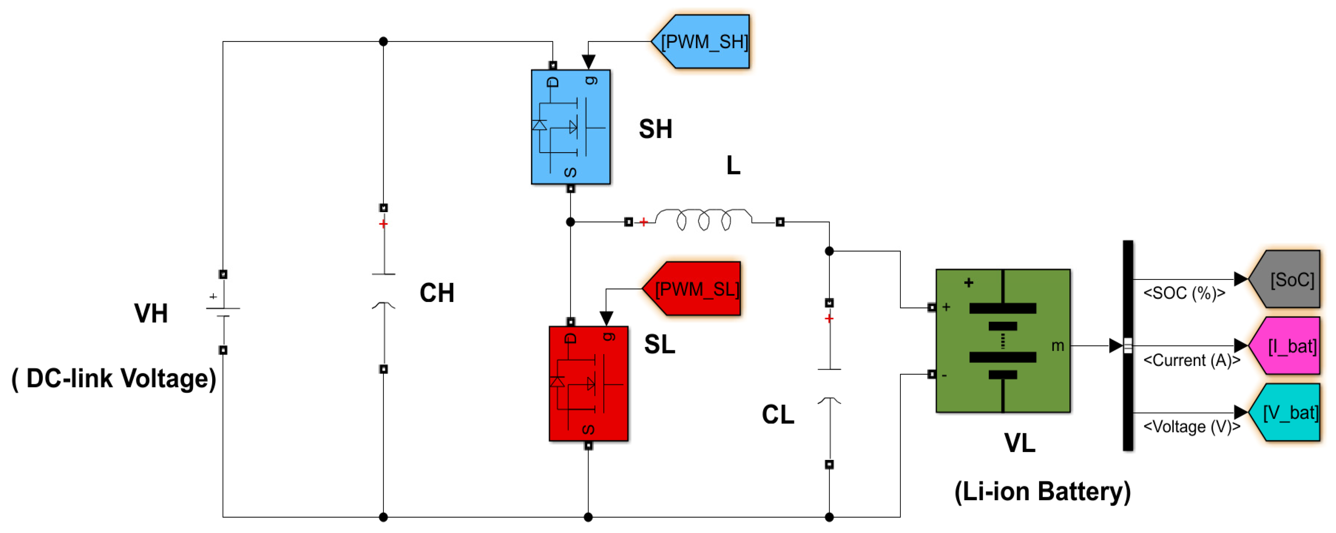
3.3. Modeling a Bidirectional DC-DC Converter for Li-Ion Battery Control

Integrating ESS-like Li-ion batteries into the DC-link of a DFIG wind turbine system has become a promising method for enhancing system performance and grid integration. By adding a battery to the DC-link, it becomes feasible to stabilize power and enhance overall system stability. The connection between the DC-link and the battery is facilitated by a bidirectional DC-DC converter. This converter plays a crucial role in controlling the battery, ensuring efficient power transfer between the battery and the DC-link [78,79,80]. Thus, the bidirectional DC-DC converter primarily aims to (a) manage the flow and direction of power to and from the battery and (b) regulate the voltage and power needs of the DC-link [81].
The bidirectional converter charges the battery when there is excess power from strong winds, and the battery stores it. When there is low wind speed or high power demand, the battery discharges to supply power to the DC-link [69]. This improves system efficiency, grid stability, and power quality by reducing the impact of sudden power changes. The battery can quickly respond by supplying or absorbing power during grid disturbances or power fluctuations, contributing to grid stability [82].
The buck–boost bidirectional DC-DC converter used in this investigation is configured as shown in Figure 7. The bidirectional DC-DC converter connects the proposed battery bank to the DFIG’s DC-link. The Li-ion battery is situated on the low-voltage (LV) side, as shown in Figure 7, and is integrated into the DFIG’s DC-link on the high-voltage (HV) side.
This converter can operate in two modes: as a buck converter or a boost converter. The choice between these modes depends on the switching state of its two MOSFET switches.
When the battery is charging, energy transfers from the DC-link to the battery through the S H   switch and S L diode. This configuration makes the converter operate as a one-way buck converter. In this mode, when the S H switch is ON, it activates the body diode of the S L   switch, keeping the S L   switch OFF. In buck mode, the current within the inductor flows from the HV side to the LV side of the circuit [55,78,83,84].
Conversely, when the battery discharges, energy is supplied from the battery to the DC-link through the S L   switch and S H   diode, causing the converter to work as a one-way boost converter. In boost mode, the current within the inductor flows from the LV side to the HV side of the circuit [55,78,83,84].
It is important to note that the battery’s terminal voltage increases during charging and decreases during discharging [85]. A summary of the operational principles of the bidirectional buck–boost converter is given in Table 2.
In the following sections, we will explore how to design the parameters and control the bidirectional DC-DC converter circuit.

3.3.1. Bidirectional DC-DC Converter Circuit Parameter Design

In DFIG power smoothing applications, a bidirectional DC-DC converter is essential for precise battery control. This converter ensures efficient power transfer between the DFIG and the battery storage system, allowing power flow in both directions. To achieve reliable power smoothing in scenarios with fluctuating DFIG output power, we need to design the key circuit parameters for the bidirectional DC-DC converter. This section provides the mathematical equations necessary for determining these parameters.
A basic bidirectional DC-DC converter, illustrated in Figure 7, consists of five primary components: two capacitors ( C H and C L ) for filtering ripples and smoothing the output waveform, two switches ( S H and S L ), and an inductor (L) to smooth the current ripple.
To calculate the appropriate values for the filter capacitance and inductance, we use the following analytical approach: we begin with the known parameters—the converter has an output power of 450 kW, a switching frequency of 25 kHz, a DC-link voltage ( V H ) of 1150 V, and a battery voltage ( V L ) of 470 V—and we assume the ripple voltage is below 1%. Here is how we design the converter parameters:
Selection of the inductor: The inductor in the bidirectional DC-DC converter is designed based on the circuit’s operating mode, which can be either continuous current mode (CCM) or discontinuous current mode (DCM), as well as the desired level of current ripple. In cases where the DC-DC converter operates in buck CCM, the inductor’s ripple current can be described as follows [84,86]:
I L = D 1   ×   V H × 1 D 1 L   ×   f s w
In Equation (31), D 1 represents the duty cycle of the switch in buck mode. This duty cycle calculation is based on the formula provided in Equation (32), as referenced in [75,83,84,87].
D 1 ( b u c k   m o d e ) = V L V H = 470 1150 = 0.4
where V L is battery voltage and V H is DC-link voltage.
By solving for L in Equation (31), we derive Equation (33):
L = D 1   ×   V   H   × 1 D 1   f s w   × I L
Likewise, when the bidirectional DC-DC converter functions in the boost CCM, we can express the inductor ripple current using Equation (34), as referenced in [86,87]:
I L = D 2   ×   V L L × f s w
By solving for L in Equation (34), we derive Equation (35):
L = D 2   ×   V L I L × f s w
In this context, D 2 stands for the duty cycle in boost mode, and we can determine its value using Equation (36), as indicated in references [84,86,87,88].
D 2 ( b o o s t   m o d e ) = 1 V L V H = 1 470 1150 = 0.6
To find the appropriate inductor value, we must first establish the ripple in the inductor current ( I L ) as shown in Equations (31) and (34). This ripple current is commonly estimated to fall within the range of 20% to 40% of the inductor current [83]. Given that the maximum current in the MOSFET corresponds to the current passing through inductor L, we can calculate the MOSFET’s maximum current using Equation (37).
I s w i t c h = P o u t V L = 450 × 10 3 470 = 957   A
So, if we select a 20% ripple, we can determine the change in inductor current ( I L ) by using Equation (38).
I L = 20 % × I s w i t c h = 0.2 × 957 = 191   A
Finally, by substituting the value of I L into Equations (33) or (35), we can calculate the suitable inductor value as follows:
L = D 2   ×   V L I L × f s w = 0.6 × 470 191 × 25 × 10 3 = 59   µ H
Selection of filter capacitors: In the buck CCM, the formula for capacitor ripple voltage can be found in Equation (40), as indicated in references [83,86]. As per the design specifications, the voltage ripple should be below 1% [83].
V C = D 1 × V H × 1 D 1 8 × L × C L × f s w 2
We can determine the value of the capacitor C L   by solving for it in Equation (40), and this calculation is performed using Equation (41).
C L = D 1 × V H × 1 D 1 8 × L × V C × f s w 2 = 0.4 × 1150 × 1 0.4 8 × 0.000059 × 0.01 × 470 × 25 × 10 3 2 = 199   µ F
Likewise, when we consider the boost CCM, we can determine the capacitor voltage using Equation (42), as referenced in [83,86]:
V C = I o × D 2 f s w × C H
To find the value of the capacitor C H , we can calculate it by solving Equation (42), and this calculation is performed using Equation (43):
C H = I o × D 2 f s w × V C = 957 × 0.6 25 × 10 3 × 1150 × 0.01 = 1997   µ F
We have organized and presented the calculated values of the buck–boost bidirectional DC-DC converter component parameters in Table 3 for easy reference and understanding.

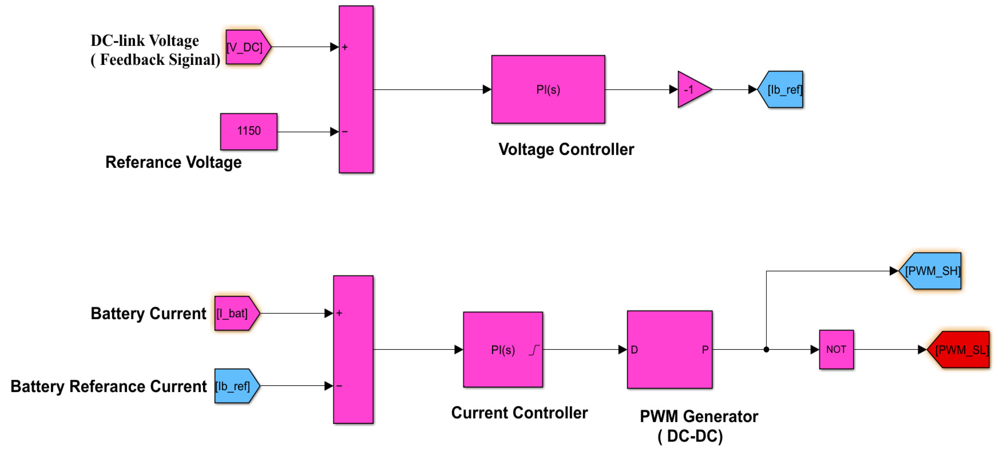
3.3.2. Li-Ion Battery Control with Bidirectional DC-DC Converter Modeling

The DC-link voltage can be effectively regulated, and the battery’s charging and discharging processes can be well controlled by precisely managing the duty cycle of the bidirectional converter. Figure 7 illustrates the use of bidirectional converters to control the Li-ion battery charging and discharging conditions. These converters are controlled through switching signals generated by PWM generators known as P W M S H and P W M S L . While charging or discharging, the proportional–integral (PI) controllers instruct switches S H and S L to turn ON or OFF based on the controller’s duty cycle.
Furthermore, Figure 8 depicts the comparison between the DC-link voltage and the nominal DC-link voltage. The resulting error is then used in a PI controller to generate i b r e f , which is a reference current for the battery. To achieve this, we employ both outer voltage feedback control and inner current control, as depicted in Figure 8. The output of the current controller is linked to the input of the DC-DC PWM generator, which then produces P W M S H and P W M S L pulses. The PWM generator plays a crucial role in these controls by regulating the operation of the MOSFET switches within the DC-DC converter.
It is important to note that the nominal battery voltage is 470 V, while the DC-link voltage is 1150 V. The PI controller uses specific parameters: [Kp Ki] = [1.5 200] for the voltage regulator and [0.5 10] for the current regulator. The pulses generated by the PWM generator, namely P W M S H and P W M S L , are used in controlling the DC-DC converter for the Li-ion battery.
Before we proceed with the system modeling, it is important to have a clear understanding of how the Li-ion battery is controlled using a bidirectional DC-DC converter. In the next subsection, we will clarify the charging and discharging characteristics of the Li-ion battery by examining the Simulink results. This understanding is crucial for the subsequent stages of system modeling.

Li-Ion Battery Charging and Discharging Characteristics

The bidirectional buck–boost converter functions as both a boost converter during battery discharge and a buck converter during battery charging. In this section, we used Simulink results to show the behavior of a Li-ion battery under both charge and discharge conditions. The simulation aims to illustrate the SoC and the switching status in these two scenarios.
In Table 3, we listed the parameters for the bidirectional buck–boost DC-DC converter. Additionally, Table 4 shows the parameter values specific to the Li-ion battery, which is designed for intermittent power smoothing. These values have been determined using the battery sizing procedure and calculations explained in Section 3.2.
Figure 9 displays the simulation result for the Li-ion battery’s SoC in the charging and discharging conditions. When the battery is charged using a DFIG DC-link, its SoC increases. Conversely, when the battery provides power to the DC-link, it discharges, causing its SoC to decrease.
During charging, the buck circuit operates with the S H switch being turned ON through PWM control from zero seconds to eight seconds, as shown in Figure 10. Conversely, during battery discharge, the boost circuit is active, and from eight seconds to fifteen seconds, the S L switch is controlled by PWM, while the S H switch is turned OFF, as depicted in Figure 10.

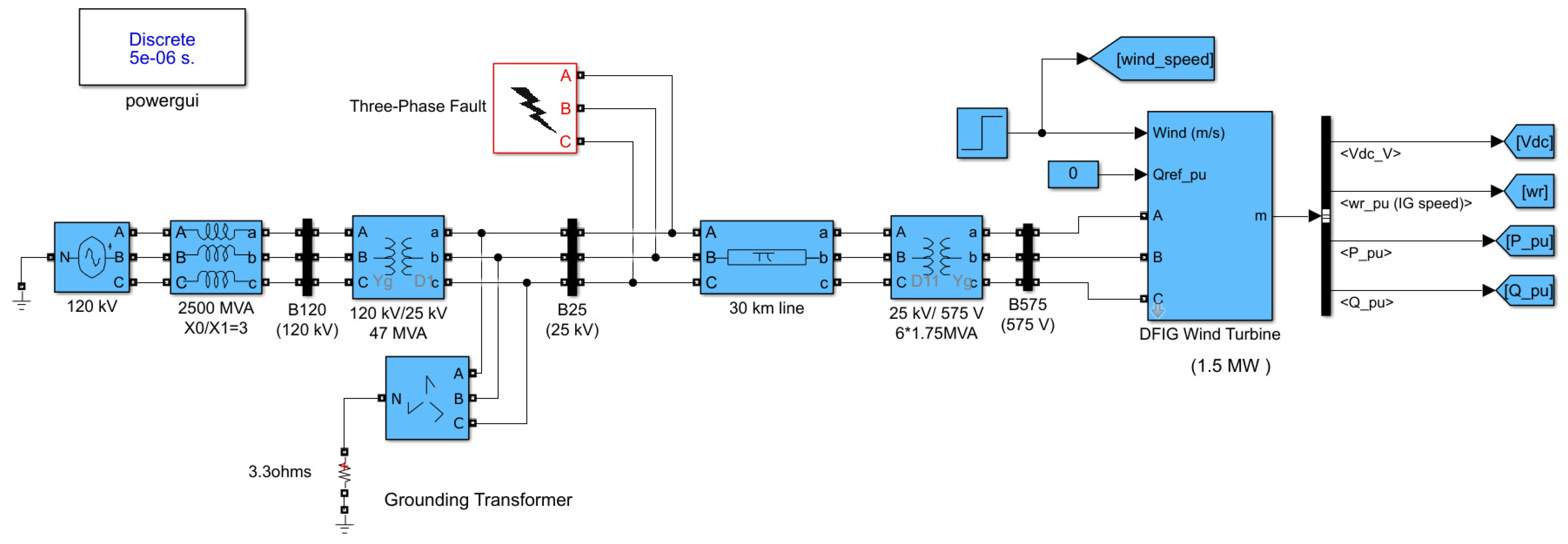
4. System Modeling and Simulation

In this study, we used MATLAB/Simulink R2022a version to model the integration of a Li-ion battery with DFIG wind turbines. Our main objective was to assess the impact of adding Li-ion batteries to the DC-link of DFIG wind turbines under varying wind conditions, with a specific focus on improving power transmission to the grid. Figure 11 illustrates the key components of this setup: a 1.5 MW DFIG wind turbine connected to a 25 kV distribution system through a step-up transformer, enabling power transfer to a 120 kV grid via transmission lines; a Li-ion battery integrated into the DFIG’s DC-link, controlled by a bidirectional DC-DC buck–boost converter; and transformers for voltage transformation and fault protection, including a step-up transformer (25 kV/120 kV) and a ground transformer.
The coordinated operation of power converters, transformers, control systems, and protective devices ensures smooth power synchronization with the grid. We obtained the parameter values for both the network and the grid-connected DFIG wind turbines from [54]. To make these parameters easily accessible for reference, they are listed in Appendix A, specifically in Table A1 (for the network) and Table A2 (for the DFIG wind turbine). These values serve as the basis for our investigation into how the Li-ion battery contributes to improving system stability and overall efficiency.
Our study aims to assess the impact of Li-ion batteries on power smoothing in grid-connected DFIG wind turbines under three different conditions:
(i)
Steady-State Operation: We first model a grid-connected DFIG wind turbine without a Li-ion battery using a Simulink model. This setup involves applying a stepped variable wind speed to the system model. The purpose is to observe and analyze the behavior of grid-connected DFIG wind turbines when Li-ion batteries are not present.
(ii)
Dynamic Transient Operation: This simulation investigates how the active and reactive power of the grid system responds under fault conditions. We introduce a three-phase-to-ground fault at the connection bus between B25 and the transmission line, with the fault cleared after one second. These simulations help us understand the dynamic transient state of the system under varying wind conditions and fault scenarios.
(iii)
With Li-ion Battery: Next, we analyze a grid-connected DFIG wind turbine that includes a Li-ion battery within the system, using a Simulink model. Like the previous scenarios, we subject the system to a stepped variable wind speed. This setup allows us to study how the presence of Li-ion batteries impacts the performance of grid-connected DFIG wind turbines under steady-state and dynamic transient conditions.
By conducting these simulations, we aimed to comprehensively evaluate and compare the performance of grid-connected DFIG wind turbines both with and without Li-ion batteries, particularly in smoothing power fluctuations.

4.1. Simulation of a DFIG Wind Turbine Model in Simulink: With and without Li-Ion Battery

To explore the role of Li-ion batteries in DFIG wind turbine systems, we developed models and conducted simulations for both scenarios: one with a grid-connected DFIG under steady-state and dynamic transient conditions and another with the addition of a Li-ion battery for both conditions. Figure 12 illustrates the Simulink model for the grid-connected DFIG wind turbine, while Figure 13 depicts the Simulink model for the DFIG equipped with a Li-ion battery connected in parallel to the DC-link.
In the next section, we will focus on simulating and evaluating the performance of a grid-connected DFIG wind turbine, both with and without the Li-ion battery. We applied stepped variable wind speeds to our system model to demonstrate how DFIG wind turbines behave in these scenarios. Specifically, we were interested in analyzing the active and reactive power waveforms under these variable wind speed conditions. The simulations were conducted for a duration of 15 s. Our goal was to gain insights into the Li-ion battery’s capabilities and limitations within the context of wind power plant applications.

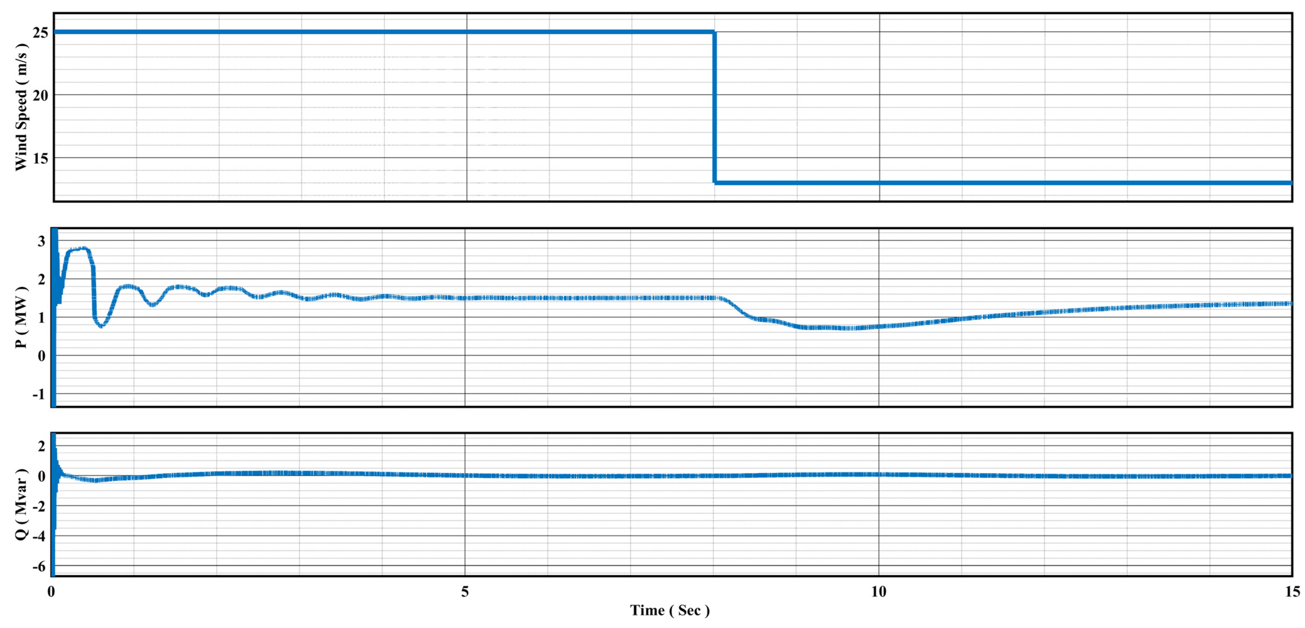
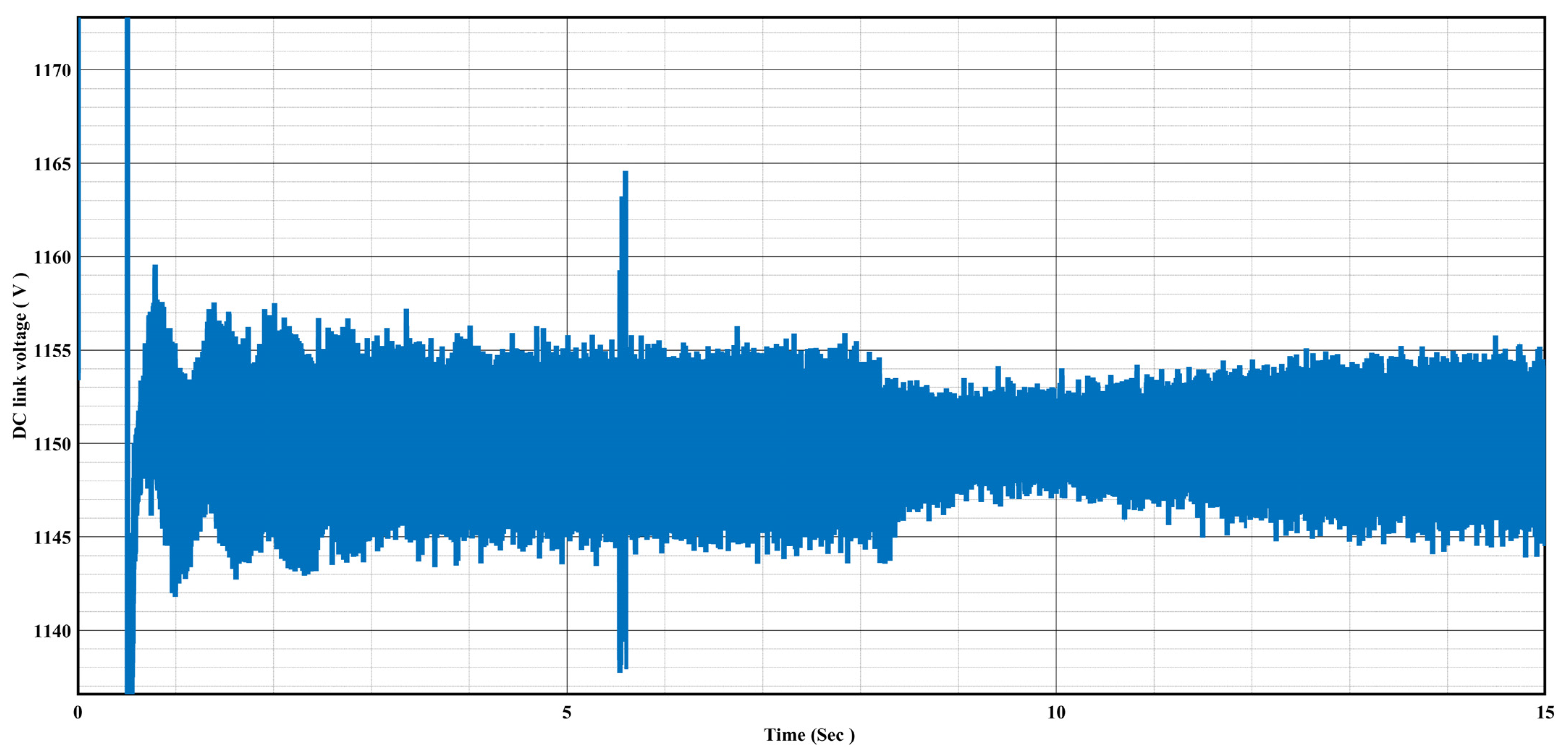
4.1.1. Performance of the DFIG in the Steady-State Condition without a Li-Ion Battery

We modeled and simulated a DFIG wind turbine under steady-state conditions without a Li-ion battery to assess its response to varying wind speeds when connected to the grid. Figure 14 illustrates how the power output, both active and reactive, of a DFIG wind turbine correlates with variations in wind speed. The wind speed is subjected to stepped variable changes, ranging from 25 m/s to 13 m/s.
As the wind speed decreases from its highest point of 25 m/s to the lowest of 13 m/s, the active output power of the DFIG wind turbine varies accordingly. When the wind speed is at its peak, the DFIG can generate its rated output power of 1.5 MW. However, as the wind speed decreases, the active output power also drops, reflecting the turbine’s reduced ability to harness wind energy and generate electricity. This relationship highlights the turbine’s performance under different wind conditions and its ability to adjust its power output accordingly.
As depicted in Figure 14, DFIG’s active power fluctuates more at startup because it takes some time for the generator’s components to coordinate and settle into a steady state. Initially, there can be power variations as the generator aligns with the grid and adapts to the desired operating conditions. Furthermore, the DFIG wind turbine consistently generates zero reactive power across the entire wind speed range. This operation signifies a power factor of 1.0, indicating that the turbine’s electrical output aligns with the grid voltage. Consequently, the DFIG wind turbine effectively manages its reactive power generation and consumption, enhancing the stability and efficiency of the electrical grid.
Furthermore, Figure 15 illustrates the DC-link voltage characteristic of a DFIG wind turbine as it varies from its nominal value of 1150 V to a maximum of 1155 V and a minimum of 1145 V. These variations in DC-link voltage correspond to changes in wind speed, which follow a stepped variable pattern ranging from 25 m/s to 13 m/s.
As the wind speed fluctuates within this range, the DC-link voltage experiences corresponding variations. When the wind speed is at its highest (25 m/s), the DC-link voltage tends to approach or reach its maximum value of 1155 V. Conversely, during periods of lower wind speed (down to 13 m/s), the DC-link voltage decreases, coming closer to or reaching its minimum value of 1145 V. Figure 15 provides insights into how the DC-link voltage of the DFIG wind turbine responds to changing wind conditions, which can be crucial for monitoring and maintaining the stability of the wind turbine system.

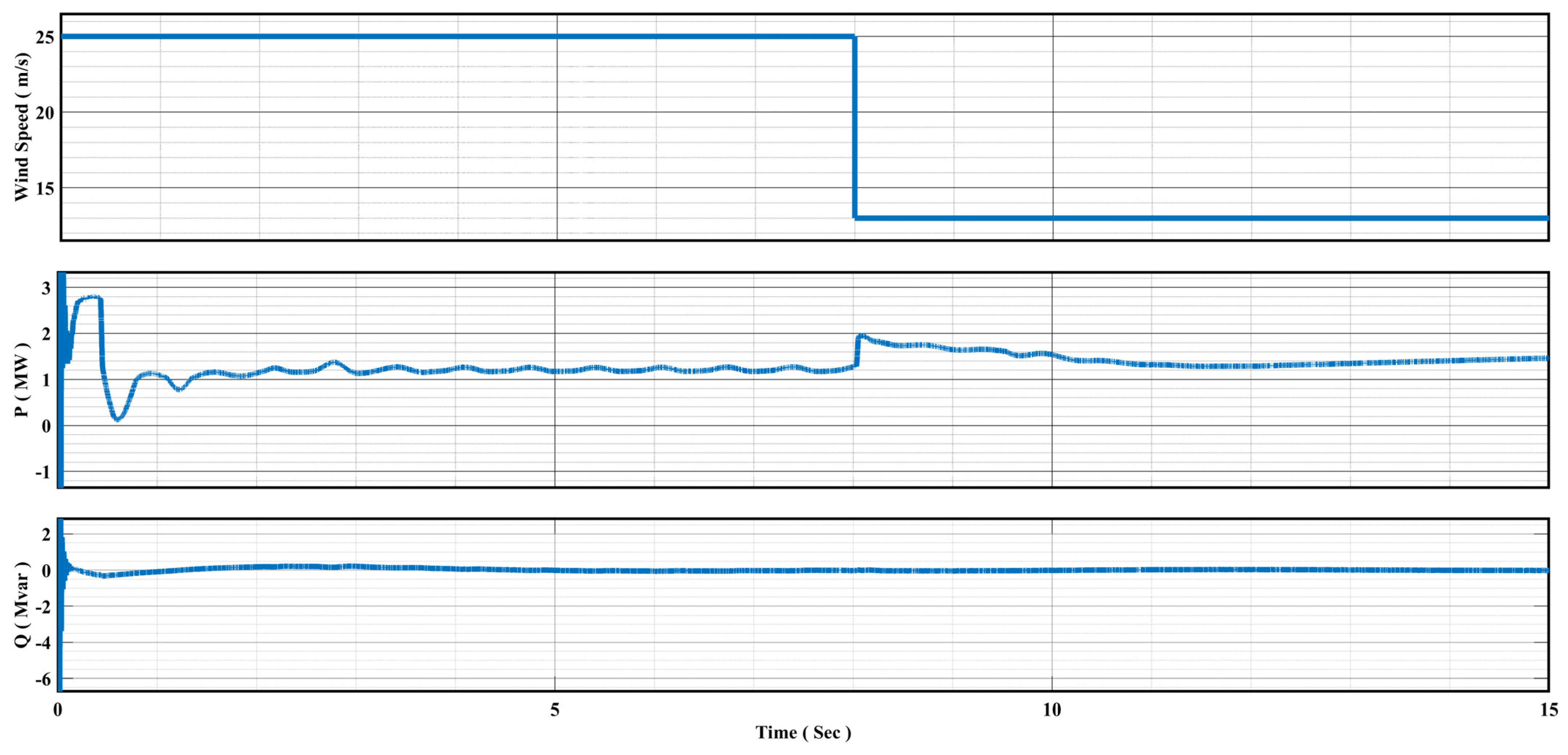
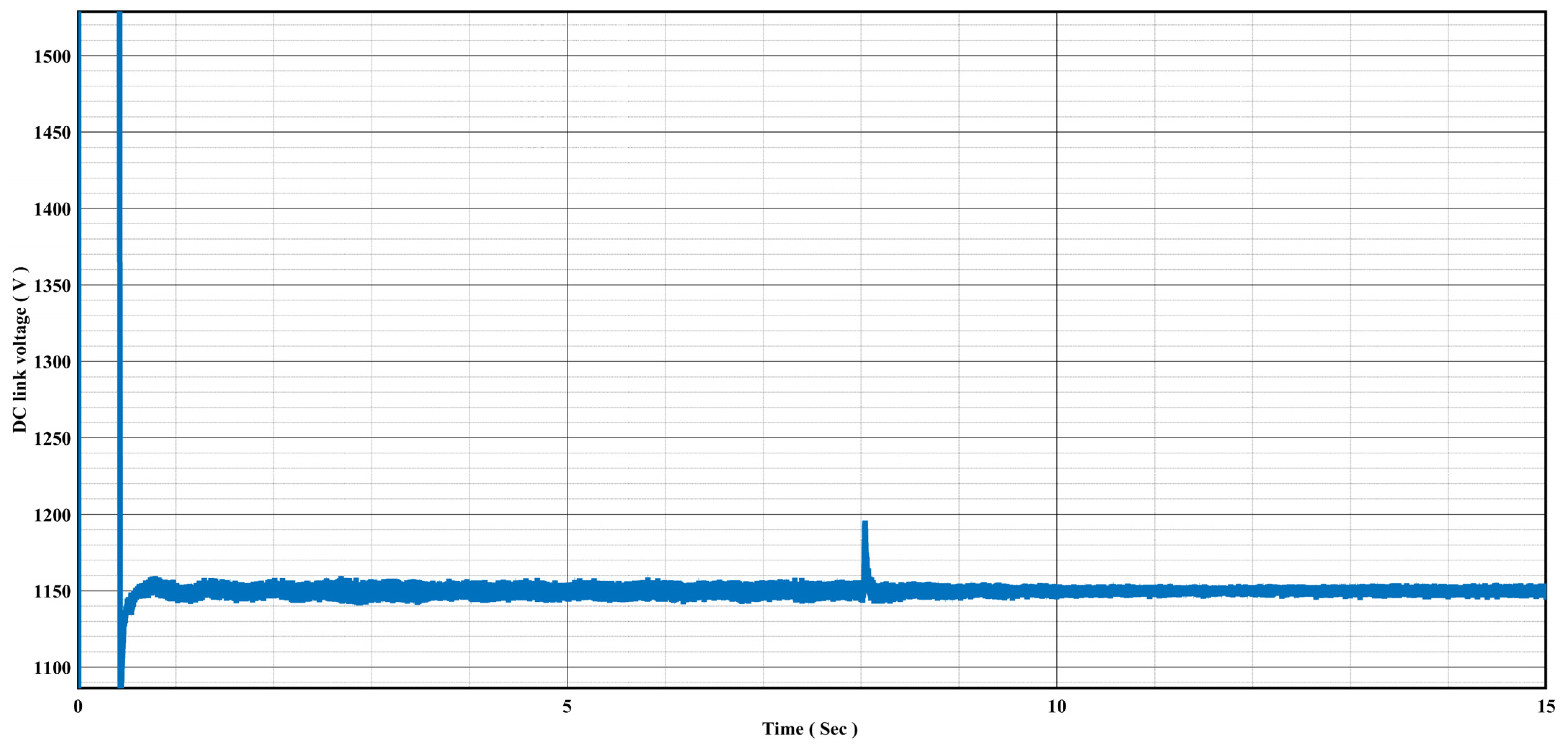
4.1.2. Performance of the DFIG in the Steady-State Condition with a Li-Ion Battery

Figure 16 illustrates how the fluctuating output power of a DFIG wind turbine is smoothed by Li-ion batteries. This graph specifically shows the relationship between active and reactive power output as wind speed fluctuates, ranging from 25 m/s (high speed) to 13 m/s (low speed).
In this scenario, the focus is on illustrating how a Li-ion battery acts as an energy buffer, smoothing out the fluctuations in the wind turbine’s output power under high and low wind speed conditions. As illustrated in Figure 14, under high wind speed conditions, the wind turbine generates a surplus of energy. The Li-ion battery takes advantage of this excess energy by charging itself, storing the additional power for later use. This charging process helps prevent overloading the electrical grid and ensures efficient energy utilization.
On the other hand, when wind speeds decrease, the wind turbine’s output power also decreases accordingly. However, the Li-ion battery steps in by discharging the stored energy, thus supplementing the power generation from the wind turbine. This discharge process helps maintain a steady power supply to the grid, even under low wind conditions.
As depicted in Figure 16, the Li-ion battery effectively stabilizes the fluctuating output power of the DFIG wind turbine. Consequently, the active output power of these generators remains nearly constant at their rated power of 1.5 MW. Simultaneously, the system operates with a power factor of 1.0, as indicated by the zero level of reactive power, highlighting its efficient performance.
The DC-link voltage with Li-ion batteries over time shows an initial period of fluctuation lasting for a few seconds, as shown in Figure 17. Following this initial phase, the voltage stabilizes and approaches the rated voltage of 1150 V, illustrating a consistent and smooth performance. This behavior suggests that the Li-ion batteries effectively regulate the DC-link voltage, ensuring it remains close to the desired rated level after an initial transient period.

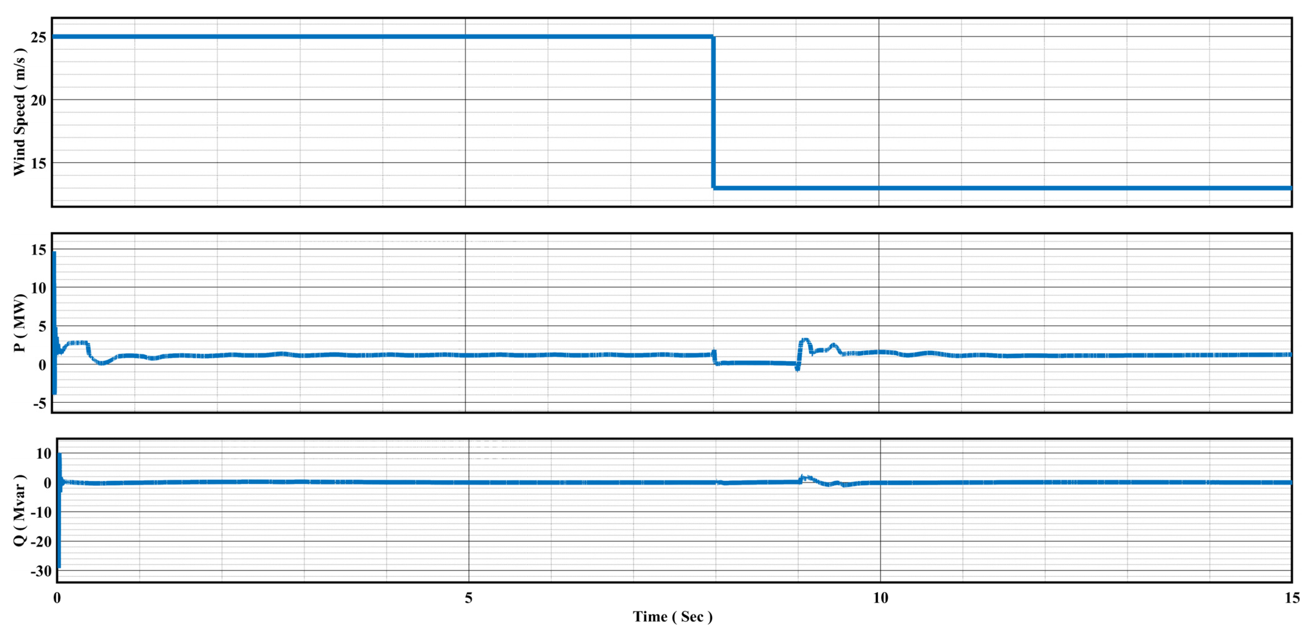
4.1.3. Performance of the DFIG under Dynamic Transient Conditions without a Li-Ion Battery

We conducted a simulation to examine how the grid behaves when a three-phase short circuit fault occurs under dynamic transient conditions, without the involvement of a Li-ion battery. Figure 18 presents the results, taking into account variable wind speeds. The fault was introduced near bus B25 of the DFIG wind turbine and occurred from 8 s to 9 s.
During the one second from 8 to 9 s, a three-phase fault had a significant impact on both active and reactive power. The active power dropped to a negative value because of the grid fault, and the reactive power became positive, indicating control responses to the situation.
Once the fault was resolved at 9 s, the system returned to its normal state. However, due to the minimum wind speed (13 m/s), the active power remained below its rated capacity. This situation could present operational challenges for the grid, and further analysis is needed to address the power deficit under such low wind conditions.

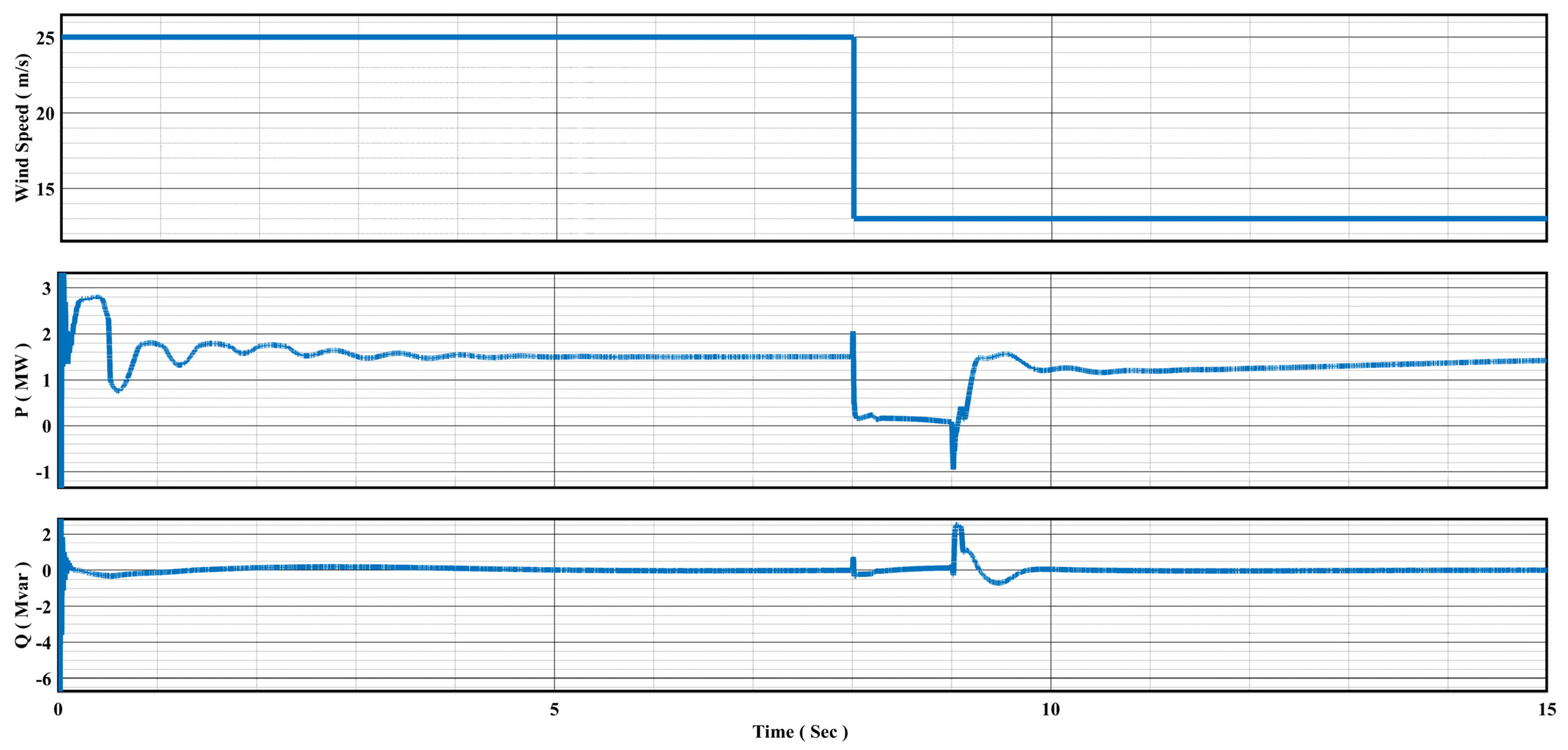
4.1.4. Performance of the DFIG under Dynamic Transient Conditions with a Li-Ion Battery

In Figure 19, when a fault occurs, the wind turbine’s active output power temporarily drops to almost zero, as expected. However, it quickly recovers once the fault is resolved, demonstrating the turbine’s capability to handle faults. During this time, the reactive power remains close to zero, indicating that the wind turbine operates efficiently with a near unity power factor.
Additionally, the Li-ion battery helps maintain a stable active power output by absorbing and releasing energy as needed, both before and after the fault event. This ensures a consistent power output, even when wind speeds vary.
As demonstrated earlier, the Li-ion battery was designed to store excess energy during high wind speeds and discharge it when wind speeds are low. We controlled the battery’s charging and discharging operations using a bidirectional DC-DC buck–boost converter, as illustrated in Figure 13. In the subsequent section, we will comprehensively validate the mathematical model, size considerations, and control techniques of the Li-ion battery, which were previously discussed in Section 3. This validation will be achieved via a thorough examination of simulation results, providing a clear and in-depth verification of these aspects.

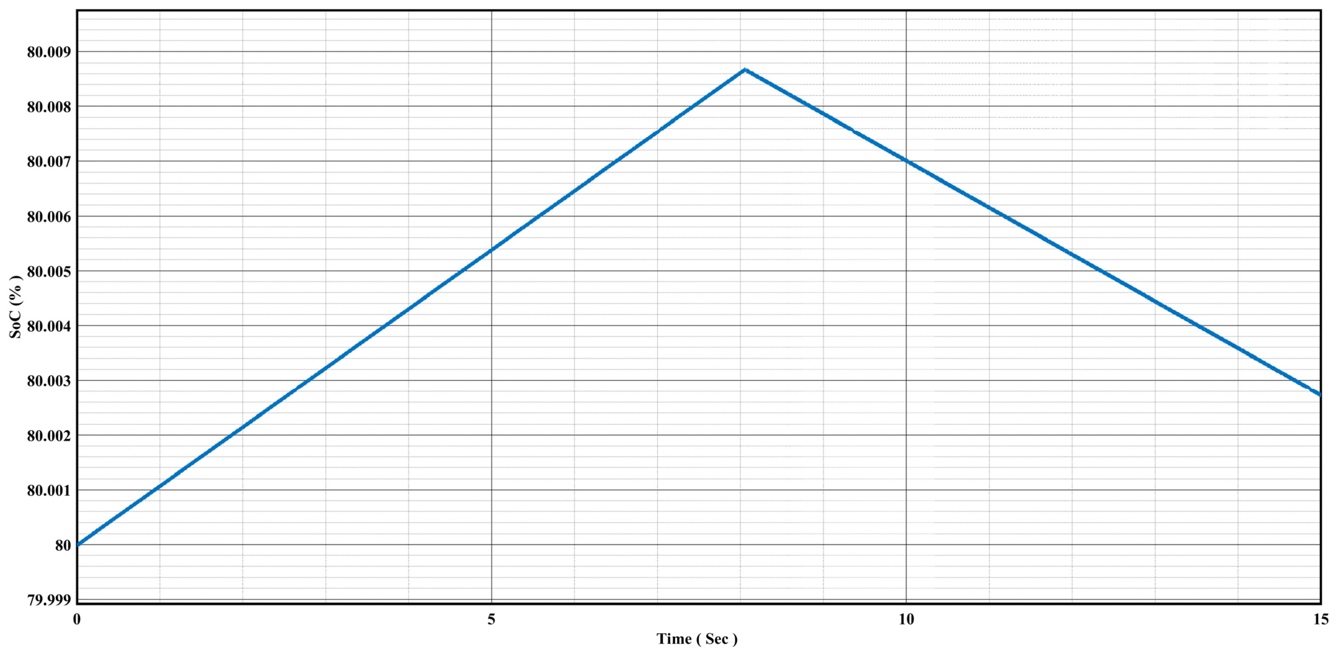
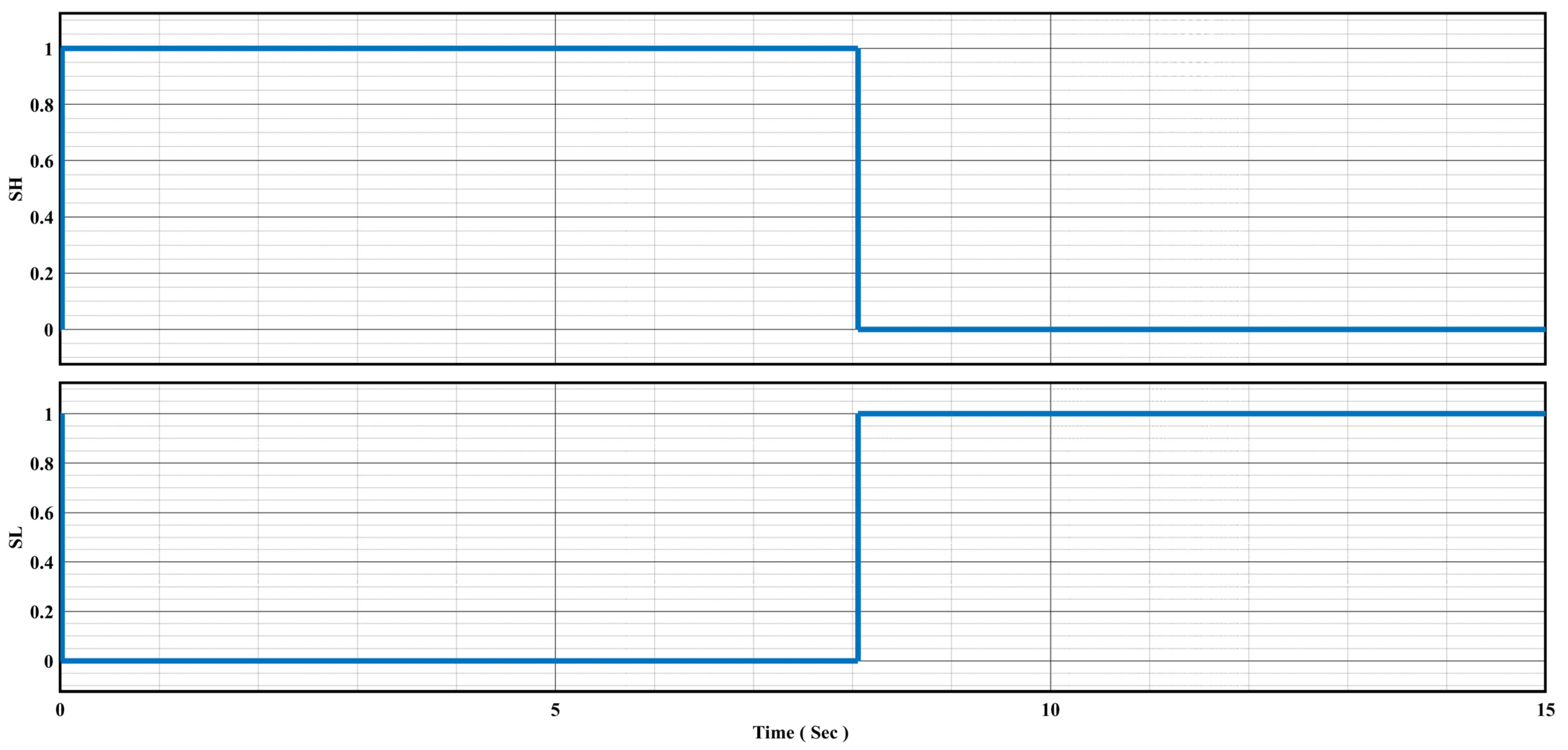
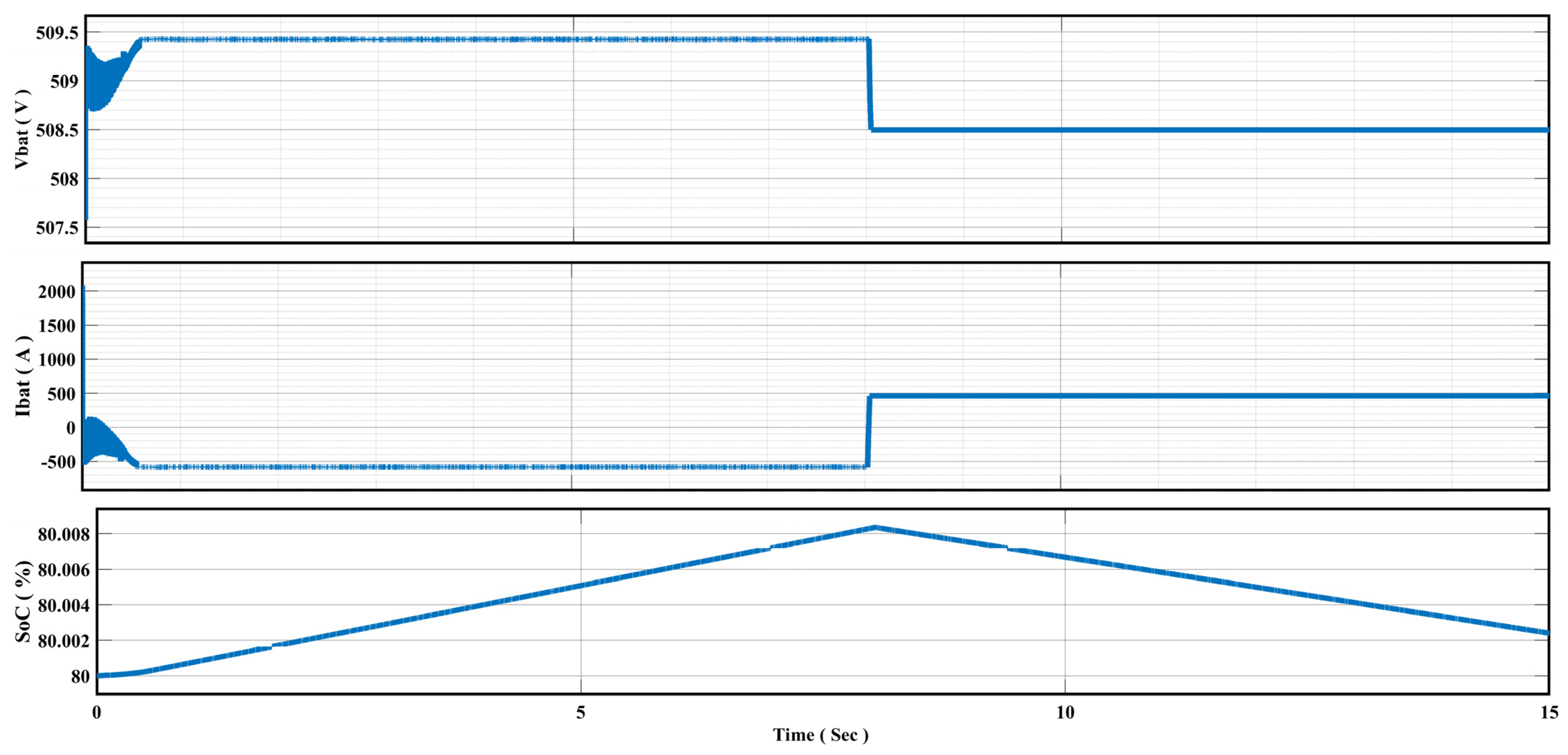
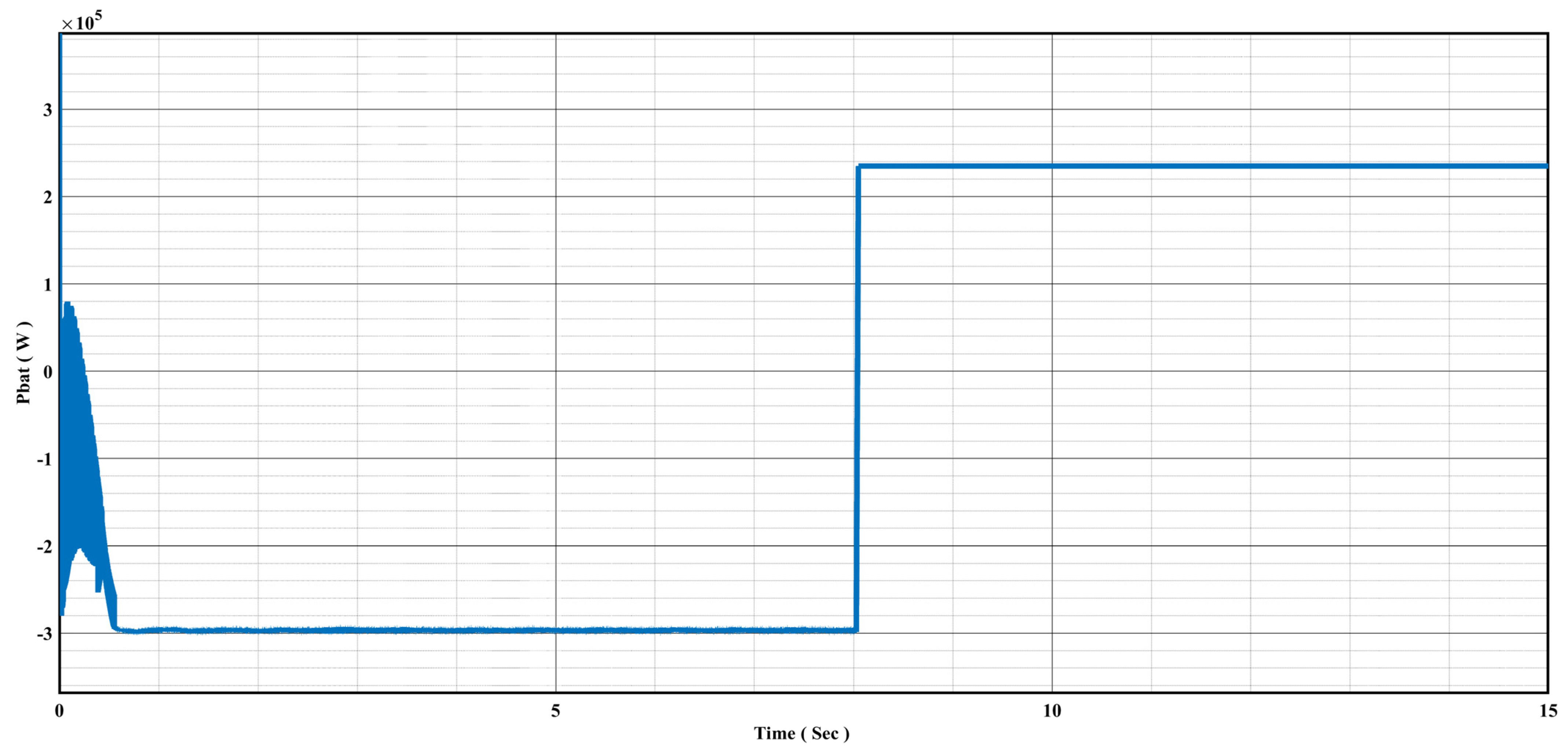
4.1.5. Li-Ion Battery Performance under Charging and Discharging Conditions

Figure 20 illustrates the simulation results that depict the Li-ion battery’s voltage, current, and SoC under charging and discharging conditions. These results help us understand how the battery responds when there are disruptions in the DC-link voltage of grid-connected DFIG wind turbines.
To demonstrate the Li-ion battery’s charging and discharging characteristics and the control capabilities of the bidirectional buck–boost DC-DC converter, we examine situations where the DC-link voltage goes beyond its rated value or falls below it. These scenarios are illustrated in Figure 15.
When the DC-link voltage experiences a sudden increase, the battery current is adjusted to redirect the excess voltage back into the grid. In this situation, the Li-ion battery switches to the charging mode, storing the surplus energy. During the charging process, the battery voltage gradually rises from zero seconds to eight seconds. Throughout this period, the battery current decreases and remains steady until the disturbance is resolved. As a result, the SoC of the battery increases, as shown in Figure 20.
Conversely, if there is a sudden decrease in the DC-link voltage, the battery current is adapted to provide the necessary voltage to the grid. The Li-ion battery transitions into the discharge mode, releasing the stored energy. During the discharge phase, the battery voltage declines, reflecting the discharge process, which occurs from eight seconds to fifteen seconds. Throughout this period, the battery current increases and remains constant until the disturbance is resolved. As a result, the SoC of the battery decreases, as shown in Figure 20.
In general, as shown in Figure 21, when there is a sudden increase in DC-link voltage beyond its rated level, the batteries absorb the excess power. Conversely, when the DC-link voltage experiences a drop below the rated value, the batteries supply additional power to maintain the desired output. It is crucial to emphasize that in this study, the batteries’ contribution is restricted to a maximum SoC of 80%. This limitation prevents the batteries from overcharging or over-discharging, which in turn optimizes their performance and extends their lifespan.

5. Conclusions

In this study, we conducted modeling and simulation experiments to assess the performance of grid-connected DFIG wind turbines, both with and without the integration of Li-ion batteries. Our findings showed that DFIG wind turbines without Li-ion batteries exhibited significant power fluctuations. To address this issue, we proposed integrating a Li-ion battery into the DFIG wind turbine’s DC-link, using a buck–boost bidirectional DC-DC converter to control the charging and discharging processes. The model we developed demonstrated that when the power generated exceeds the grid’s power demand, the battery charges, and the DC-DC converter operates in buck mode. Conversely, during periods of low power generation, the battery discharges, and the DC-DC converter switches to boost mode to ensure a consistent power supply to the grid. As a result, DFIG wind turbines consistently produce 1.5 MW of active power. Additionally, the system maintains a power factor of 1.0, which means it operates with maximum efficiency, and no reactive power is generated. Our simulation results conclusively show that integrating a Li-ion battery into the DC-link of DFIG wind turbines effectively mitigates power fluctuations caused by varying wind speeds. This enhancement contributes to a smoother and more stable grid power supply, making Li-ion batteries a valuable solution for addressing the impact of wind speed fluctuations on grid-connected DFIG wind turbines.

Author Contributions

In this paper, H.A.B. modeled the system, conducted the analysis, and drafted the manuscript. M.V. and K.A.F. provided study supervision and manuscript review. T.C., M.B., M.M., A.A.K. and J.V.M. reviewed and edited the manuscript. All authors have read and agreed to the published version of the manuscript.

Funding

This research received no external funding.

Data Availability Statement

Data are contained within the article.

Acknowledgments

We would like to express our gratitude to the Network for Advancement of Sustainable Capacity in Education and Research in Ethiopia (NASCERE) at Jimma University, Ethiopia, and Vrije Universiteit (VUB), Brussels, Belgium, for their generous support in awarding a joint Ph.D. scholarship to the primary author throughout this study.

Conflicts of Interest

The authors declare no conflict of interest.

Appendix A. System Parameters

Table A1. Network parameter values for the grid-connected DFIG wind turbine.
EquipmentParameterValueUnit
120 kV grid
equivalent
Nominal voltage120kV
Positive sequence phase0deg
Frequency60Hz
Three-phase
Mutual
Inductance Z1-Z0
Positive sequence inductance(L1)0.015H
Zero-sequence inductance (Lo)0.046H
Positive sequence resistances (R1)0.576Ω
Zero sequence resistances (Ro)1.728Ω
Three-phase
transformer
(120 KV/25 KV)
Capacity47MVA
Winding one connection (ABC terminals)Yg-
Winding two connection (ABC) terminalsDelta(D1)-
Primary Voltage120kV
Secondary Voltage25kV
Frequency60Hz
Primary resistance (R1)0.002pu
Primary inductance (L1)0.08pu
Secondary resistance (R2)0.002pu
Secondary inductance (L2)0.08pu
Magnetization resistance (Rm)500Ω
Magnetization inductance (Lm)500H
Three-phase transformer
(25 KV/575 V)
Capacity10.5MVA
Winding one connection (ABC terminals)D11-
Winding two connection (ABC) terminalsYg-
Primary voltage25kV
Secondary voltage575V
Frequency60Hz
Primary resistance (R1)0.0008pu
Primary inductance (L1)0.025pu
Secondary resistance (R2)0.0008pu
Secondary inductance (L2)0.025pu
Magnetization resistance (Rm)500Ω
Magnetization inductance (Lm)500H
Grounding
transformer
Capacity100MVA
Nominal voltage (Vn)25kV
Frequency60Hz
Zero sequence resistance (Ro)0.025pu
Zero sequence reactance (Xo)0.75pu
Magnetization resistance (Rm)500Ω
Magnetization reactance (Xo)500Ω
Feeder (three-phase
PI section line)
Positive sequence resistance (R1)0.1153Ω/km
Zero sequence resistance (Ro)0.413Ω/km
Positive sequence inductance (L1)1.05 × 10⁻³Ω/km
Zero sequence inductance (Lo)3.32 × 10⁻³Ω/km
Positive sequence capacitance (C1)11.33 × 10⁻⁹Ω/km
Zero sequence capacitance (Co)5.01 × 10⁻⁹Ω/km
length30km
The frequency used for RLC60Hz
Bus 575The nominal voltage used for pu575V
Base power (3-phase)10MVA
Bus B25The nominal voltage used for pu25KV
Base power (3-phase)10MVA
Bus B120The nominal voltage used for pu120KV
Base power (3-phase)10MVA
Table A2. Parameter values for DFIG’s generator, turbine, drive train, and controller.
ParametersValueUnit
Generator data
Capacity10MVA
Nominal voltage (L-L)575 VrmsV
Frequency60Hz
Stator resistance (Rs)0.023pu
Stator inductance (Lls)0.18pu
Rotor resistance (Rr’)0.016pu
Rotor inductance (Llr’)0.16pu
Magnetizing inductance (Lm)2.9pu
Generator inertia constant (H)0.685s
Pole pairs3p
Friction factor0.01pu
Turbine data
Nominal mechanical output power1.5MW
Wind speed at nominal speed11m/s
Initial wind speed11m/s
Converters data
Grid-side converter maximum current0.8pu
Grid-side coupling inductor (L)0.3pu
Grid-side coupling resistor (R)0.003pu
Nominal DC bus voltage1150V
DC bus capacitor100,000 × 10−6F
Line filter capacitor120 × 103var
Drive train data
Wind turbine inertia constant (H)4.32s
Shaft spring constant referring to high-speed shaft1.11pu
Shaft mutual damping1.5pu
Turbine initial speed1.2pu
Initial output torque0.83pu
Control parameters
DC voltage regulator gain (kp)8-
DC voltage regulator gain (ki)400-
Grid-side converter current regulator gain(kp)0.83-
Grid-side converter current regulator gain(ki)5-
Speed regulator gain (kp)3-
Speed regulator gain (ki)0.6-
Rotor-side converter regulator gain (kp)0.6-
Rotor-side converter regulator gain (ki)8-
Reactive power regulator gain (ki_var)0.05-
Voltage regulator gain (ki_volt)20-
Pitch controller gain (kp)150-
Pitch compensation gain (kp)3-
Pitch compensation gain (ki)30-
Frequency of the grid-side PWM carrier2700Hz
Frequency of the rotor-side PWM carrier1620Hz
Maximum pitch angle27degree
Maximum rate of change in pitch angle10deg/s

References

  1. IRENA. Renewable Energy Capacity Highlights. 2021. Available online: https://www.irena.org/-/media/Files/IRENA/Agency/Publication/2021/Apr/IRENA_-RE_Capacity_Highlights_2021.pdf?la=en&hash=1E133689564BC40C2392E85026F71A0D7A9C0B91 (accessed on 20 December 2022).
  2. Vijayakumar, K.; Kumaresan, N.; Gounden, N.G.A.; Tennakoon, S.B. Real and reactive power control of hybrid excited wind-driven grid-connected doubly fed induction generators. IET Power Electron. 2013, 6, 1197–1208. [Google Scholar] [CrossRef]
  3. Chhipą, A.A.; Chakrabarti, P.; Bolshev, V.; Chakrabarti, T.; Samarin, G.; Vasilyev, A.N.; Ghosh, S.; Kudryavtsev, A. Modeling and Control Strategy of Wind Energy Conversion System with Grid-Connected Doubly-Fed Induction Generator. Energies 2022, 15, 6694. [Google Scholar] [CrossRef]
  4. Sarita, K.; Devarapalli, R.; Rai, P. Modeling and control of dynamic battery storage system used in hybrid grid. Energy Storage 2020, 2, e146. [Google Scholar] [CrossRef]
  5. Behabtu, H.A.; Coosemans, T.; Berecibar, M.; Fante, K.A.; Kebede, A.A.; Van Mierlo, J.; Messagie, M. Performance Evaluation of Grid-Connected Wind Turbine Generators. Energies 2021, 14, 6807. [Google Scholar] [CrossRef]
  6. Abo-khalil, A.G. Grid Connection Control of DFIG in Variable Speed Wind Turbines under Turbulent Conditions. Int. J. Renew. Energy Res. 2019, 9, 1260–1271. [Google Scholar]
  7. Riouch, T.; El-Bachtiri, R. A coordinated control for smoothing output power of a DFIG based wind turbine. In Proceedings of the 2013 International Renewable and Sustainable Energy Conference (IRSEC), Quarzazate, Morocco, 7–9 March 2013; pp. 304–309. [Google Scholar]
  8. Masaud, T. Modeling, Analysis, Control and Design Application Guidelines of Doubly Fed Induction Generator (DFIG) for Wind Power Applications. 2013. Available online: https://www.proquest.com/docview/1444319883 (accessed on 13 April 2022).
  9. Esmaili, A.; Nasiri, A. Power smoothing and power ramp control for wind energy using energy storage. In Proceedings of the 2011 IEEE Energy Conversion Congress and Exposition, Phoenix, AZ, USA, 17–22 September 2011; pp. 922–927. [Google Scholar]
  10. Chen, T.-H.; Liao, R.-N.; Yang, C.-Y.; Chiang, Y.-H. Application of Grid-Level Battery Energy Storage System to Wind Power Fluctuation Smoothing. J. Clean Energy Technol. 2015, 4, 201–204. [Google Scholar] [CrossRef]
  11. Gwabavu, M.; Raji, A. Dynamic Control of Integrated Wind Farm Battery Energy Storage Systems for Grid Connection. Sustainability 2021, 13, 3112. [Google Scholar] [CrossRef]
  12. Kook, K.S.; McKenzie, K.; Liu, Y.; Atcitty, S. A study on applications of energy storage for the wind power operation in power systems. In Proceedings of the 2006 IEEE Power Engineering Society General Meeting, Montreal, QC, Canada, 18–22 June 2006; pp. 1–5. [Google Scholar]
  13. Wei, Z.; Moon, B.Y.; Joo, Y.H. Smooth Wind Power Fluctuation Based on Battery Energy Storage System for Wind Farm. J. Electr. Eng. Technol. 2014, 9, 2134–2141. [Google Scholar] [CrossRef]
  14. Zeng, J.; Zhang, B.; Mao, C.; Wang, Y. Use of Battery Energy Storage System to Improve the Power Quality and Stability of Wind Farms. In Proceedings of the 2006 International Conference on Power System Technology, Chongqing, China, 22–26 October 2006; pp. 1–6. [Google Scholar]
  15. Hennessy, T.; Kuntz, M. The multiple benefits of integrating electricity storage with wind energy. In Proceedings of the IEEE Power Engineering Society General Meeting, San Francisco, CA, USA, 12–16 June 2005; Volume 2, pp. 1952–1953. [Google Scholar]
  16. Jiang, Z.; Yu, X. Modeling and control of an integrated wind power generation and energy storage system. In Proceedings of the 2009 IEEE Power & Energy Society General Meeting, Calgary, AB, Canada, 26–30 July 2009; pp. 1–8. [Google Scholar]
  17. Behabtu, H.A.; Messagie, M.; Coosemans, T.; Berecibar, M.; Anlay Fante, K.; Kebede, A.A.; Mierlo, J.V. A Review of Energy Storage Technologies’ Application Potentials in Renewable Energy Sources Grid Integration. Sustainability 2020, 12, 10511. [Google Scholar] [CrossRef]
  18. Amrouche, S.O.; Rekioua, D.; Rekioua, T.; Bacha, S. Overview of energy storage in renewable energy systems. Int. J. Hydrog. Energy 2016, 41, 20914–20927. [Google Scholar] [CrossRef]
  19. Belfedhal, S.A.; Berkouk, E.M.; Meslem, Y.; Soufi, Y. Modeling and control of wind power conversion system with a flywheel energy storage system and compensation of reactive power. Int. J. Renew. Energy Res. 2012, 2, 528–534. [Google Scholar]
  20. Šćekić, L.; Mujović, S.; Radulović, V. Pumped Hydroelectric Energy Storage as a Facilitator of Renewable Energy in Liberalized Electricity Market. Energies 2020, 13, 6076. [Google Scholar] [CrossRef]
  21. Yang, Y.; Han, Y.; Jiang, W.; Zhang, Y.; Xu, Y.; Ahmed, A.M. Application of the Supercapacitor for Energy Storage in China: Role and Strategy. Appl. Sci. 2022, 12, 354. [Google Scholar] [CrossRef]
  22. Aghatehrani, R.; Kavasseri, R.; Thapa, R.C. Power smoothing of the DFIG wind turbine using a small energy storage device. In Proceedings of the IEEE PES General Meeting, Minneapolis, MN, USA, 25–29 July 2010; pp. 1–6. [Google Scholar]
  23. Nielsen, K.E.; Molinas, M. Superconducting Magnetic Energy Storage (SMES) in power systems with renewable energy sources. In Proceedings of the 2010 IEEE International Symposium on Industrial Electronics (ISIE 2010), Bari, Italy, 4–7 July 2010; pp. 2487–2492. [Google Scholar]
  24. Shi, J.; Tang, Y.; Ren, L.; Li, J.; Chen, S. Application of SMES in wind farm to improve voltage stability. Phys. C 2008, 468, 2100–2103. [Google Scholar] [CrossRef]
  25. Ibrahim, H.; Belmokhtar, K.; Ghandour, M. Investigation of Usage of Compressed Air Energy Storage for Power Generation System Improving—Application in a Microgrid Integrating Wind Energy. Energy Procedia 2015, 73, 305–316. [Google Scholar] [CrossRef]
  26. Castellani, B.; Morini, E.; Nastasi, B.; Nicolini, A.; Rossi, F. Small-Scale Compressed Air Energy Storage Application for Renewable Energy Integration in a Listed Building. Energies 2018, 11, 1921. [Google Scholar] [CrossRef]
  27. Mesbahi, T.; Ouari, A.; Ghennam, T.; Berkouk, E.M.; Rizoug, N.; Mesbahi, N.; Meradji, M. A stand-alone wind power supply with a Li-ion battery energy storage system. Renew. Sustain. Energy Rev. 2014, 40, 204–213. [Google Scholar] [CrossRef]
  28. Kawakami, N.; Iijima, Y.; Fukuhara, M.; Bando, M.; Sakanaka, Y.; Ogawa, K.; Matsuda, T. Development and field experiences of stabilization system using 34MW NAS batteries for a 51MW wind farm. In Proceedings of the 2010 IEEE International Symposium on Industrial Electronics, Bari, Italy, 4–7 July 2010; pp. 2371–2376. [Google Scholar]
  29. Xu, X.; Bishop, M.; Donna, O.; Chen, H. Application and modeling of battery energy storage in power systems. CSEE J. Power Energy Syst. 2016, 2, 82–90. [Google Scholar] [CrossRef]
  30. Deng, Z.; Xu, Y.; Gu, W.; Fei, Z. Finite-time convergence robust control of battery energy storage system to mitigate wind power fluctuations. Int. J. Electr. Power Energy Syst. 2017, 91, 144–154. [Google Scholar] [CrossRef]
  31. Silva, C.F.; De Jesus, J.M.F. A Model of a Battery Energy Storage System for Power Systems Stability Studies. 2020, pp. 1–8. Available online: https://fenix.tecnico.ulisboa.pt/downloadFile/1689244997255585/Celso_jrnl.pdf (accessed on 21 June 2022).
  32. Ganthia, B.P.; Suriyakrishnaan, K.; Prakash, N.; Harinarayanan, J.; Thangaraj, M.; Mishra, S. Comparative Analysis on Various Types of Energy Storage Devices for Wind Power Generation. J. Phys. Conf. Ser. 2022, 2161, 012066. [Google Scholar] [CrossRef]
  33. Lu, S.; Yin, Z.; Liao, S.; Yang, B.; Liu, S.; Liu, M. An asymmetric encoder—Decoder model for Zn-ion battery lifetime prediction. Energy Rep. 2022, 8, 33–50. [Google Scholar] [CrossRef]
  34. Wu, G.; Yoshida, Y.; Minakawa, T. Mitigation of Wind Power Fluctuation by Combined Use of Energy Storages with Different Response Characteristics. Energy Procedia 2011, 12, 975–985. [Google Scholar] [CrossRef]
  35. Marinelli, M.; Morini, A.; Silvestro, F. Modeling of DFIG Wind Turbine and Lithium Ion Energy Storage System. In Proceedings of the 2010 Complexity in Engineering (COMPENG), Rome, Italy, 22–24 February 2010; pp. 43–45. [Google Scholar]
  36. Verma, N.; Kumar, N.; Kumar, R. Battery energy storage-based system damping controller for alleviating sub-synchronous oscillations in a DFIG-based wind power plant. Prot. Control. Mod. Power Syst. 2023, 8, 32. [Google Scholar] [CrossRef]
  37. Okedu, K.E.; Kalam, A. Comparative Study of Grid Frequency Stability Using Flywheel-Based Variable-Speed Drive and Energy Capacitor System. Energies 2023, 16, 3515. [Google Scholar] [CrossRef]
  38. Singh, P.; Arora, K.; Rathore, U.C.; Yang, E.; Joshi, G.P.; Son, K.C. Performance Evaluation of Grid-Connected DFIG-Based WECS with Battery Energy Storage System under Wind Alterations Using FOPID Controller for RSC. Mathematics 2023, 11, 2100. [Google Scholar] [CrossRef]
  39. Abouobaida, H.; Cherkaoui, M. Modeling and control of doubly fed induction (DFIG) Wind energy conversion system. J. Electr. Eng. 2015, 15, 1–12. [Google Scholar]
  40. Mahmoud, M.M.; Atia, B.S.; Esmail, Y.M.; Bajaj, M.; Wapet, D.E.M.; Ratib, M.K.; Hossain, B.; AboRas, K.M.; Abdel-Rahim, A.-M.M. Evaluation and Comparison of Different Methods for Improving Fault Ride-through Capability in Grid-Tied Permanent Magnet Synchronous Wind Generators. Int. Trans. Electr. Energy Syst. 2023, 2023, 7717070. [Google Scholar] [CrossRef]
  41. Hadoune, A.; Mouradi, A.; Mimet, A.; Chojaa, H.; Dardabi, C.; Gulzar, M.M.; Alqahtani, M.; Khalid, M. Optimizing direct power control of DFIG-based WECS using super-twisting algorithm under real wind profile. Front. Energy Res. 2023, 11, 1261902. [Google Scholar] [CrossRef]
  42. Sahri, Y.; Tamalouzt, S.; Belaid, S.L.; Bajaj, M.; Ghoneim, S.S.; Zawbaa, H.M.; Kamel, S. Performance improvement of Hybrid System based DFIG-Wind/PV/Batteries connected to DC and AC grid by applying Intelligent Control. Energy Rep. 2023, 9, 2027–2043. [Google Scholar] [CrossRef]
  43. da Silva, P.L.T.; Rosas, P.A.C.; Castro, J.F.C.; Marques, D.d.C.; Aquino, R.R.B.; Rissi, G.F.; Neto, R.C.; Barbosa, D.C.P. Power Smoothing Strategy for Wind Generation Based on Fuzzy Control Strategy with Battery Energy Storage System. Energies 2023, 16, 6017. [Google Scholar] [CrossRef]
  44. Tang, Y.; Yang, C.; Yan, Z.; Xue, Y.; He, Y. Coordinated Control of a Wind Turbine and Battery Storage System in Providing Fast-Frequency Regulation and Extending the Cycle Life of Battery. Front. Energy Res. 2022, 10, 927453. [Google Scholar] [CrossRef]
  45. Zhu, D.; Guo, X.; Tang, B.; Hu, J.; Zou, X.; Kang, Y. Feedforward Frequency Deviation Control in PLL for Fast Inertial Response of DFIG-Based Wind Turbines. IEEE Trans. Power Electron. 2023, 1–12. [Google Scholar] [CrossRef]
  46. Liu, K.; Sheng, W.; Li, Z.; Liu, F.; Liu, Q.; Huang, Y.; Li, Y. An energy optimal schedule method for distribution network considering the access of distributed generation and energy storage. IET Gener. Transm. Distrib. 2023, 17, 2996–3015. [Google Scholar] [CrossRef]
  47. Li, M.; Yang, M.; Yu, Y.; Lee, W.-J. A Wind Speed Correction Method Based on Modified Hidden Markov Model for Enhancing Wind Power Forecast. IEEE Trans. Ind. Appl. 2022, 58, 656–666. [Google Scholar] [CrossRef]
  48. Lin, X.; Liu, Y.; Yu, J.; Yu, R.; Zhang, J.; Wen, H. Stability analysis of Three-phase Grid-Connected inverter under the weak grids with asymmetrical grid impedance by LTP theory in time domain. Int. J. Electr. Power Energy Syst. 2022, 142, 108244. [Google Scholar] [CrossRef]
  49. Liao, K.; Lu, D.; Wang, M.; Yang, J. A Low-Pass Virtual Filter for Output Power Smoothing of Wind Energy Conversion Systems. IEEE Trans. Ind. Electron. 2022, 69, 12874–12885. [Google Scholar] [CrossRef]
  50. Rana, M.; Uddin, M.; Sarkar, R.; Meraj, S.T.; Shafiullah, G.M.; Muyeen, S.M.; Islam, A.; Jamal, T. Application of energy storage technology in grid-connected new energy power generation. In Grid-Scale Energy Storage Systems and Applications; Elsevier: Amsterdam, The Netherlands, 2019; pp. 203–241. [Google Scholar] [CrossRef]
  51. Poudel, R.; Krishnan, V.; Reilly, J.; Koralewicz, P.; Baring-Gould, I. Integration of Storage in the DC Link of a Full Converter-Based Distributed Wind Turbine. In Proceedings of the 2021 IEEE Power & Energy Society General Meeting (PESGM), Washington, DC, USA, 25–29 July 2021; pp. 1–5. [Google Scholar]
  52. Vargas, R.Z.; Lopes, J.C.; Colque, J.C.; Azcue, J.L.; Sousa, T. Energy Storage System Integration with Wind Generation for Primary Frequency Support in the Distribution Grid. Simpósio Bras. Sist. Elétricos 2021, 1, SBSE2020. [Google Scholar] [CrossRef]
  53. Simon, L.; Swarup, K.S. Modeling and control of DFIG with battery management system for grid power leveling. In Proceedings of the 2016 IEEE International Conference on Power Electronics, Drives and Energy Systems (PEDES), Trivandrum, India, 14–17 December 2016; pp. 1–6. [Google Scholar]
  54. Gagnon, R. Wind Farm—DFIG Detailed Model—MATLAB & Simulink. MATLAB. Available online: https://www.mathworks.com/help/physmod/sps/ug/wind-farm-dfig-detailed-model.html;jsessionid=a2a435e13fc5108445d84a28ca36 (accessed on 16 July 2021).
  55. Sarrias, R.; Fernández, L.M.; García, C.A.; Jurado, F. Coordinate operation of power sources in a doubly-fed induction generator wind turbine/battery hybrid power system. J. Power Sources 2012, 205, 354–366. [Google Scholar] [CrossRef]
  56. Aktarujjaman, M.; Kashem, M.A.; Negnevitsky, M.; Ledwich, G. Smoothing Output Power of a Doubly Fed Wind Turbine with an Energy Storage System. Aust. Univ. Power Eng. Conf. 2006, 2006, 1–8. [Google Scholar]
  57. Zhu, Y.; Zang, H.; Cheng, L.; Gao, S. Output Power Smoothing Control for a Wind Farm Based on the Allocation of Wind Turbines. Appl. Sci. 2018, 8, 980. [Google Scholar] [CrossRef]
  58. Mohod, S.W.; Hatwar, S.M.; Aware, M.V. Grid Support with Variable Speed Wind Energy System and Battery Storage for Power Quality. Energy Procedia 2011, 12, 1032–1041. [Google Scholar] [CrossRef]
  59. Sugawara, E.; Nikaido, H. Properties of AdeABC and AdeIJK efflux systems of Acinetobacter baumannii compared with those of the AcrAB-TolC system of Escherichia coli. Antimicrob. Agents Chemother 2014, 58, 7250–7257. [Google Scholar] [CrossRef]
  60. Pant, A. Modelling and Design of Grid Connected Doubly Fed Induction Generator. Master’s Thesis, Texas Tech University, Lubbock, TX, USA, 2019. [Google Scholar]
  61. Abu-Rub, H.; Malinowski, M.; Al-Haddad, K. Power Electronics for Renewable Energy Systems, Transportation and Industrial Applications, 1st ed.; WILEY: Chichester, UK, 2014. [Google Scholar] [CrossRef]
  62. Mwaniki, J.; Lin, H.; Dai, Z. A Condensed Introduction to the Doubly Fed Induction Generator Wind Energy Conversion Systems. J. Eng. 2017, 2017, 1–18. [Google Scholar] [CrossRef]
  63. Zhang, Y.; Ula, S. Comparison and evaluation of three main types of wind turbines. In Proceedings of the Transmission and Distribution Exposition Conference: 2008 IEEE PES Powering Toward the Future, PIMS 2008, Chicago, IL, USA, 21–24 April 2008; pp. 1–6. [Google Scholar] [CrossRef]
  64. Nikolian, A.; Firouz, Y.; Gopalakrishnan, R.; Timmermans, J.-M.; Omar, N.; Van den Bossche, P.; Van Mierlo, J. Lithium Ion Batteries—Development of Advanced Electrical Equivalent Circuit Models for Nickel Manganese Cobalt Lithium-Ion. Energies 2016, 9, 360. [Google Scholar] [CrossRef]
  65. Nikolian, A.; De Hoog, J.; Fleurbay, K.; Timmermans, J.; Van De Bossche, P.; Van Mierlo, J. Classification of Electric modelling and Characterization methods of Lithium-ion Batteries for Vehicle Applications. In Proceedings of the European Electric Vehicle Congress, Brussels, Belgium, 3–5 December 2014; pp. 1–15. [Google Scholar]
  66. Chen, M.; Rincon-Mora, G.A. Accurate Electrical Battery Model Capable of Predicting Runtime and I–V Performance. IEEE Trans. Energy Convers. 2006, 21, 504–511. [Google Scholar] [CrossRef]
  67. He, H.; Xiong, R.; Fan, J. Evaluation of Lithium-Ion Battery Equivalent Circuit Models for State of Charge Estimation by an Experimental Approach. Energies 2011, 4, 582–598. [Google Scholar] [CrossRef]
  68. Mathworks. Battery. Available online: https://nl.mathworks.com/help/sps/powersys/ref/battery.html (accessed on 23 July 2023).
  69. Enang, C.M.; Johnson, B.K. Bidirectional dc-dc Converter Control in Battery-Supercapacitor Hybrid Energy Storage System. In Proceedings of the 2020 IEEE Power & Energy Society Innovative Smart Grid Technologies Conference (ISGT), Washington, DC, USA, 17–20 February 2020; pp. 1–5. [Google Scholar]
  70. Kim, Y.; Harrington, R.J.; Kim, Y.; Harrington, R.J. Analysis of Various Energy Storage Systems for Variable Speed Wind Turbines; IntechOpen: London, UK, 2018. [Google Scholar] [CrossRef]
  71. Giannoutsos, S.V.; Manias, S.N. A cascade control scheme for a grid connected Battery Energy Storage System (BESS). In Proceedings of the 2012 IEEE International Energy Conference (ENERGYCON 2012), Florence, Italy, 9–12 September 2012; pp. 469–474. [Google Scholar]
  72. Emeric, B. Key Performance Indicators for the Monitoring of Large-Scale Battery Storage Systems BRUN Emeric Approved Examiner. 2019. Available online: https://kth.diva-portal.org/smash/record.jsf?pid=diva2%3A1371050&dswid=-6871 (accessed on 14 October 2022).
  73. Wang, Y.; Zhou, Z.; Botterud, A.; Zhang, K.; Ding, Q. Stochastic coordinated operation of wind and battery energy storage system considering battery degradation. J. Mod. Power Syst. Clean Energy 2016, 4, 581–592. [Google Scholar] [CrossRef]
  74. Ganti, V.C.; Singh, B.; Aggarwal, S.K.; Kandpal, T.C. DFIG-Based Wind Power Conversion with Grid Power Leveling for Reduced Gusts. IEEE Trans. Sustain. Energy 2011, 3, 12–20. [Google Scholar] [CrossRef]
  75. Qu, L.; Qiao, W. Constant Power Control of DFIG Wind Turbines with Supercapacitor Energy Storage. IEEE Trans. Ind. Appl. 2011, 47, 359–367. [Google Scholar] [CrossRef]
  76. Smith, S.C.; Sen, P.; Kroposki, B. Advancement of energy storage devices and applications in electrical power system. In Proceedings of the 2008 IEEE Power and Energy Society General Meeting—Conversion and Delivery of Electrical Energy in the 21st Century, Pittsburgh, PA, USA, 20–24 July 2008; pp. 1–8. [Google Scholar]
  77. Lee, K.H.; Malmedal, K.; Sen, P.K. Conceptual Design and Cost Estimate for a Stand-Alone Residential Photovoltaic System. In Proceedings of the 2012 IEEE Green Technologies Conference, Trivandrum, India, 18–20 December 2012; pp. 1–6. [Google Scholar]
  78. Naresh, M.; Soni, U.K.; Tripathi, R.K. Power Flow Control and Power Quality Improvement in DFIG Based Wind Energy Conversion System Using Neuro Fuzzy System. Int. J. Appl. Eng. Res. 2018, 13, 5236–5243. Available online: http://www.ripublication.com (accessed on 21 September 2022).
  79. Venkatesu, N.; Scholar, M.T. Analysis, Design and Simulation of Bidirectional DC-DC Converter. Int. J. Eng. Res. Technol. 2015, 4, 197–202. [Google Scholar] [CrossRef]
  80. Hu, H.; Cheng, X.; Wang, J.; Zou, X. Control and Simulation of Bi-directional DC/DC Converter for 5KW Distributed Wind/Solar Hybrid System. In Proceedings of the 2017 29th Chinese Control and Decision Conference (CCDC), Chongqing, China, 28–30 May 2017; pp. 7039–7044. [Google Scholar]
  81. Bharath, K.R.; Choutapalli, H.; Kanakasabapathy, P. Control of Bidirectional DC-DC Converter in Renewable based DC Microgrid with Improved Voltage Stability. Int. J. Renew. Energy Res. 2018, 8, 871–877. [Google Scholar] [CrossRef]
  82. Huang, S.; Wu, Q.; Guo, Y.; Rong, F. Optimal active power control based on MPC for DFIG-based wind farm equipped with distributed energy storage systems. Int. J. Electr. Power Energy Syst. 2019, 113, 154–163. [Google Scholar] [CrossRef]
  83. Sutikno, T.; Aprilianto, R.A.; Purnama, H.S. Application of non-isolated bidirectional DC–DC converters for renewable and sustainable energy systems: A review. Clean Energy 2023, 7, 293–311. [Google Scholar] [CrossRef]
  84. Li, B.Y.; Xu, C.; Li, C.; Guan, Z. Working principle analysis and control algorithm for bidirectional DC-DC converter. J. Power Technol. 2017, 97, 327–335. [Google Scholar]
  85. Gambhir, J.; Thakur, T.; Verma, H. Wind Energy Integration with Grid Using an Energy Storage. In Proceedings of the World Congress on Engineering, London, UK, 29 June–1 July 2016; Volume I. [Google Scholar]
  86. Zhang, G.; Dai, Y.; Cui, J. Design and Realization of a Bi-directional DC/DC Converter in photovoltaic power system. In Proceedings of the 2016 International Forum on Energy, Environment and Sustainable Development, Shenzhen, China, 16–17 April 2016. [Google Scholar]
  87. Chao, K.; Tseng, M.; Huang, C.; Liu, Y.; Huang, L. Design and Implementation of a Bidirectional DC-DC Converter for Stand-Alone Photovoltaic Systems the Proposed Bidirectional Buck-Boost Converter. Int. J. Comput. Consum. Control 2013, 2, 44–55. [Google Scholar]
  88. Suresh, K.; Arulmozhiyal, R. Design and Implementation of Bi-Directional DC-DC Converter for Wind Energy System. Circuits Syst. 2016, 7, 3705–3722. [Google Scholar] [CrossRef]
Figure 1. Distributed configurations of ESS integrated with WTG.
Energies 16 07637 g001
Figure 2. Centralized configuration of an ESS integrated with WTGs.
Energies 16 07637 g002
Figure 3. Power coefficient variation with a tip-to-speed ratio for different pitch angles.
Energies 16 07637 g003
Figure 4. DFIG equivalent circuit in the dq reference frame [61].
Energies 16 07637 g004
Figure 5. Simplified diagram of a lithium-ion battery model [43].
Energies 16 07637 g005
Figure 6. Cycle life versus DoD curve for a lithium-ion NMC battery [73].
Energies 16 07637 g006
Figure 7. Equivalent circuit of the buck–boost bidirectional DC-DC converter.
Energies 16 07637 g007
Figure 8. Bidirectional DC-DC converter control scheme.
Energies 16 07637 g008
Figure 9. Li-ion battery SoC in the charging and discharging conditions.
Energies 16 07637 g009
Figure 10. S H and S L switching state in the charging and discharging conditions.
Energies 16 07637 g010
Figure 11. Single line diagram for a Li-ion battery connected to the DC-link of the DFIG.
Energies 16 07637 g011
Figure 12. Simulink model of a DFIG wind turbine without a Li-ion battery.
Energies 16 07637 g012
Figure 13. Simulink model of a DFIG wind turbine with a Li-ion battery.
Energies 16 07637 g013
Figure 14. DFIG wind turbine performance under steady-state conditions, without a Li-ion battery.
Energies 16 07637 g014
Figure 15. Changes in DC-link voltage with varying wind speeds, without a Li-ion battery.
Energies 16 07637 g015
Figure 16. DFIG wind turbine performance under steady-state conditions, with a Li-ion battery.
Energies 16 07637 g016
Figure 17. DC-link voltage, with a Li-ion battery.
Energies 16 07637 g017
Figure 18. DFIG wind turbine performance under dynamic transient conditions, without a Li-ion battery.
Energies 16 07637 g018
Figure 19. DFIG wind turbine performance under dynamic transient conditions, with a Li-ion battery.
Energies 16 07637 g019
Figure 20. Voltage, current, and SoC of the Li-ion battery under charging and discharging conditions.
Energies 16 07637 g020
Figure 21. Battery power under charging and discharging conditions.
Energies 16 07637 g021
Table 1. Summary of battery bank sizing.
Power Capacity
(kW)
Discharge Time
(h)
DoDEnergy (kWh) of the Battery BankBattery Nominal Voltage (V)Battery Bank
Configuration
450 kW8 h0.57200 kWh470 V39S100P
Table 2. Summary of the operational principles of the bidirectional buck–boost converter.
Mode of OperationSwitch ONSwitch OFFPower FlowBattery State
Buck mode S H followed by S L Diode S L followed by S H DiodeFrom DC-link to BatteryBattery Charging
Boost mode S L followed by S H Diode S H followed by S L DiodeFrom Battery to DC-linkBattery Discharging
Table 3. Component values computed for the bidirectional DC-DC converter circuit.
Serial NumberParametersValues
1Duty cycle, D 1   ( b u c k   m o d e ) 0.4
2Duty cycle, D 2   ( b o o s t   m o d e ) 0.6
3Switching frequency25 kHz
3Converter output power450 kW
4DC-link voltage ( V H )1150 V
5Battery voltage ( V L )470 V
6Inductor59 µH
7Ripple in inductor current20%
8The capacitor on the LV side ( C L )199 µF
9The capacitor on the HV side ( C H )1997 µF
10Ripple in capacitor voltage1%
Table 4. Li-ion battery parameter values.
Battery ParametersValueUnit
Nominal Voltage470V
Rated Capacity15,000Ah
Initial State of Charge80%
Battery Response Time1s
Cut-off Voltage352V
Fully Charged Voltage547V
Nominal Discharge Current652A
Internal Resistance0.000313ohms
Capacity at Nominal Voltage13,565Ah
Disclaimer/Publisher’s Note: The statements, opinions and data contained in all publications are solely those of the individual author(s) and contributor(s) and not of MDPI and/or the editor(s). MDPI and/or the editor(s) disclaim responsibility for any injury to people or property resulting from any ideas, methods, instructions or products referred to in the content.

