Article

Performance Improvement and Emission Reduction Potential of Blends of Hydrotreated Used Cooking Oil, Biodiesel and Diesel in a Compression Ignition Engine

1
Department of Automobile Engineering, Faculty of Engineering and Technology, SRM Institute of Science and Technology, NCR Campus, Ghaziabad 201204, India
2
Department of Mechanical Engineering, Delhi Technological University, Shahbad Daulatpur, Delhi 110042, India
*
Author to whom correspondence should be addressed.
Energies 2023, 16(21), 7431; https://doi.org/10.3390/en16217431
Submission received: 3 September 2023 / Revised: 23 September 2023 / Accepted: 31 October 2023 / Published: 3 November 2023
(This article belongs to the Collection Energy Transition towards Carbon Neutrality)

Abstract

:
The positive effect of decarbonizing the transport sector by using bio-based fuels is high. Currently, biodiesel and ethanol are the two biofuels that are blended with fossil fuels. Another technology, namely, hydroprocessing, is also gaining momentum for producing biofuels. Hydrotreated vegetable oil (HVO) produced using this process is a potential drop-in fuel due to its improved physiochemical properties. This study aimed to reduce the fossil diesel content by blending 20% and 30% HVO and 5%, 10% and 15% waste cooking oil biodiesel on a volume basis. The blends were used to conduct a thorough performance examination of a single-cylinder compression ignition engine. The thermal efficiency of the engine was enhanced by the addition of biodiesel to the blend. The efficiency increased as the proportion of biodiesel in the mix increased, although it was still less efficient than diesel. The maximum improvement in thermal efficiency of 4.35% was observed with 20% blending of HVO and 15% blending of biodiesel compared with 20% blending of HVO and diesel. However, the HC (decrease of 30%), CO (decrease of 23.5%) and smoke (decrease of 21.1%) emissions were observed to be the lowest with 30% blending of HVO and 15% blending of biodiesel. A fuzzy-logic-based Taguchi method and Grey’s method were then applied to find the best blend of HVO, biodiesel and diesel. The combination of the two methods made it easier to carry out multi-objective optimization. The brake thermal efficiency (BTE), smoke and NO emissions were selected as the output parameters to optimize the HVO and biodiesel blend. The optimization study showed that 30% blending of HVO and 15% blending of biodiesel was the best blend, which was authenticated using the confirmation experiment.

1. Introduction

Pure air is important for the well-being of life on this planet. However, the incessant use of fossil fuels, particularly by the road transport sector, has degraded the air quality over the years. Although enormous improvements in the engine and exhaust after-treatment systems have been made, they are still contributing to the emission of harmful gases. The main toxic components of the engine exhaust gas are unburned hydrocarbons (HCs), carbon monoxide (CO), nitrogen oxides (NOxs), sulphur oxide and particulate matter. Prolonged exposure to toxic fumes can have an ill effect on human health, such as cardiovascular and respiratory ailments, cancer or nervous system breakdown [1]. It is therefore imperative to look for alternatives, not only from a human health point of view but also from the fact that fossil resources are depleting and the costs incurred are rapidly increasing. One such alternative is biofuel, whose share in the global energy consumption by the transport sector is a mere 4%. Fatty acid methyl ester (FAME), also known as biodiesel, which is produced by the transesterification of vegetable oil using methanol as a catalyst, has a 32% share in the world biofuel market [2]. Another technology known as hydroprocessing can also be utilized in producing diesel-like fuel from vegetable oil [3,4]. Similar to FAME, this technology produces fuel using a variety of feedstocks without competing with food production. Hence, the fuel can be classified as a second-generation fuel [5]. Both fuels require natural gas to obtain the chemicals necessary for their processes, i.e., methanol is required by FAME and hydrogen is required for hydroprocessing [6]. Moreover, well-to-wheel analysis of carbon footprints shows that hydrotreated vegetable oil (HVO) is more sustainable than diesel [7].
In the presence of a catalyst, the raw feedstock is hydrotreated, and to further improve the quality, isomerization of the intermediates, carboxylic acid, monoglyceride and diglyceride treatment is also carried out [8,9,10]. The individual stage processes define the resulting products formed, which can be either normal paraffins or a mixture of iso- and n-paraffinic hydrocarbons, which are free from sulphur and aromatics and have a low level of toxicity [11]. The chemical structure of HVO provides good auto-ignition properties and enables cleaner combustion [8]. Due to the higher cetane number of HVO, the start of combustion is faster, especially at low and medium loads [12]. Other advantages of HVO are better cold-start properties, shorter primary combustion, less white smoke and low noise [13]. Due to low lubricity, it is suggested that the content of HVO while blending with diesel should be limited to 50% [14]. Also, it was found that 30% blending of HVO in diesel can meet the EN590 norms [15]. Studies showed significant reductions in particulate, NOx, CO and HC emissions with the use of HVO in heavy-duty engines [3,16] or in tractors [17]. Similar results were also reported in non-mobile applications, such as underground mining operations [18] and gensets [19].
When comparing diesel with HVO, it was found that HVO fuel droplets penetrate more than diesel, resulting in the formation of a more combustible homogeneous mixture. Furthermore, lower physical ignition delay and improved mixture dispersion result in lower local temperatures [15,20]. Vo et al. [14] found no difference in the cone angle with an up to 30% blend of HVO with diesel and mineral diesel. Moreover, the spray cone angle was significantly wider with neat HVO compared with diesel. Cheng et al. [20] and Bohl et al. [15] also made similar observations. Moreover, modelling showed no difference in fuel penetration and distribution. The results were confirmed experimentally in an optical engine. In contrast, Preuss et al. [21] used a high-pressure injection chamber to investigate spray characteristics and found a longer liquid penetration length but smaller vapor phase penetration for HVO compared with diesel. Engine testing on a large scale was conducted by Neste Oil, Helsinki Region Transport, VTT Technical Research Centre and Proventia Emission Control [22]. The tests conducted on nearly 300 EURO IV buses showed a reduction in emissions with a 30% blend of HVO in diesel fuel. Moreover, the studies did not find any reliability issues [23,24]. When using HVO in heavy-duty engines, the unburned hydrocarbon emissions were reduced by 48%, carbon monoxide emissions were reduced by 28%, NOx emissions were reduced by 10% and particulate matter emissions were reduced by 28% [16]. Also, aromatics were not produced by HVO combustion. In light-duty engines, however, the emissions were reduced with HVO but the results were engine dependent [12]. Some studies found a reduction in NOx emissions with unchanged particulate levels, whereas some studies suggest a trade-off. Sugiyama et al. [25] explained that this trade-off was dependent upon the use of either single injection or split injection of the fuel. The HVO ignited earlier with a single fuel injection with a lower heat release rate, resulting in lower NOx emissions but higher particulate emissions. With the split-injection strategy, the main combustion remained the same and HVO was ignited earlier. The lower chemical propensity of HVO was the governing mechanism for lower particulate creation during split injection. Wu et al. [26] also found that the smoke emission was halved with HVO compared with diesel for the entire engine operating map. However, Bortel et al. [13] found that the particulate number was unaffected by the HVO, but still, an 80% reduction in HVO was found.
The literature shows that there is scope for realizing the full potential of HVO properties by recalibrating the engine. In this context, Ezzitouni et al. [27] tuned the pilot fuel injection and found improvement in thermal efficiency by delaying the pilot fuel injection, especially under cold-start conditions. Mikulski et al. [28] also found an improvement in combustion efficiency with the same strategy. However, the particulate emissions were found to increase due to less premixed combustion caused by advancing the injection. The HVO recalibration potential was investigated by Aatola et al. by varying the main injection timing and fixed pilot injection [3]. The NOx–PM trade-off was found to be variable at different speeds and loads. Moreover, the particulate emissions were 30–40% lower with HVO than diesel for a given NOx level, thereby providing additional control flexibility. Double pilot injection was used by Liu et al. [29] for a 60% HVO blend. The authors found that only the combustion of the first pilot was advanced, whereas other injected fuel burnt with similar rates and timings as diesel, HVO and FAME. The timings of the pilot and major injections were changed by Dimitriadis et al. [30], who discovered complex trends in efficiency and emissions as a result of the superposition of the aforementioned effects. Since HVO’s high cetane number and chemical structure make it less likely to produce particle emissions, exhaust gas recirculation is another method that researchers have studied and offers better trade-offs than HVO [31]. Lehto et al. [32] and Liu et al. [29] confirmed this in their studies. Liu et al. [29], by applying a Miller cycle and an advanced start of ignition, showed a reduction in PM and NOx simultaneously.
The literature shows that there are inherent advantages to using HVO in a diesel engine, mainly due to its properties, such as low viscosity shortening the evaporation time and improving the homogenization process. However, a high cetane number, along with its paraffinic structure, shortens the ignition delay but lengthens the soot oxidation time [33]. Hence, additives can also be potentially explored for improving the combustion process. Dobrzynska et al. [34] doped cerium dioxide and ferrocene nanoparticles into a blend of diesel (B7: blends of diesel and 7% FAME) and HVO. An 11-year-old passenger vehicle was tested on an NEDC cycle. The authors found a reduction in particulate emissions and a slight increase in NOx emission with cerium dioxide doping. In contrast, ferrocene doping resulted in a reduction in NOx emissions, along with a particulate matter reduction. Apart from the abovementioned study, no other work (as per the authors’ knowledge) is available in the literature that explored the potential of additives/blends of biofuel in the blends of diesel and HVO. The authors noted in their earlier work [19,35] that using 30% hydrotreated oil produced lower emissions, although the thermal efficiency was poor. Moreover, although the emissions were greater with the 20% blend of hydrotreated oil than with the 30% blend, the efficiency with the 20% blend was higher. In the current work, the addition of biodiesel was investigated as a potential remedy for the deficiencies of the two samples. The novelty of this study lies in the fact that experimental work was carried out by mixing waste cooking oil biodiesel in a blend of diesel and hydrotreated oil. The aim of this study was to determine a relationship between the addition of biofuels to diesel and a change in engine exhaust emission levels from an agricultural diesel engine. Such low-cost diesel engines are abundantly available on farms and they have fixed injection timing and pressure with no after-treatment system in place. To optimize the engine performance in a full-load condition, a fuzzy-logic-based Taguchi method was also used to find the best blend of HVO and biodiesel.

2. Materials and Methods

2.1. Properties of Test Fuels

The waste cooking oil used in the present study was obtained from the hostel mess of Delhi Technological University. Impurities were first removed from the oil using a filtration process. The oil was then heated to 100 °C so that any water content could be boiled off. The oil was hydrotreated in hydrogen in a batch reactor at 330 °C and 4 MPa. The catalyst used for the study was 2% ruthenium, cobalt and manganese supported on alumina. After the reaction, the obtained bio-crude oil was distilled. The oil obtained in the range of 180–370 °C boiling temperature was considered as the hydrotreated fuel. The detailed procedure for obtaining the hydrotreated oil can be studied in the previous work [10].
The process utilized to produce biodiesel can be studied in detail elsewhere [36]. In a batch reactor, one litre of the sample was heated at 60 °C and was stirred continuously at 300 rpm. The optimal methanol-to-oil ratio was found to be 5:1, while the NaOH content required was 0.5% on a weight basis. Separately, both sodium hydroxide and methanol were added and agitated until the NaOH was entirely dissolved in the methanol. The feedstock was filtered to eliminate pollutants before being boiled to remove the moisture. The utilized oil was then cooled to 60 °C before the NaOH/methanol combination was added. The reactions were complete after 1 h, as the liquid had turned translucent. The resultant mixture was left for 10 to 12 h to settle in a separator. After the settling phase, two layers were visible: the upper layer was the methyl ester of the utilized oil, while the lower layer contained glycerol. The biodiesel was washed with water to get rid of the extra catalysts after the two layers had been separated. The residual water in the biodiesel was subsequently removed by heating it above the boiling point of water. The amount of biodiesel produced using this technique was over 90%.
The blends were prepared by adding the test fuels in the required proportions in a vessel. To improve the homogeneity of the test sample, it was stirred with the help of a magnetic stirrer for 2 h. The blend containing 80% diesel and 20% hydrotreated oil was designated as H20D80, whereas the blend containing 70% diesel and 30% hydrotreated oil was designated as H30D70. The blend containing 75% diesel, 20% hydrotreated oil and 5% biodiesel was designated as H20B5, while the blend containing 65% diesel, 30% hydrotreated oil and 5% biodiesel was designated as H30B5. Similarly, other blends were designated as H20B10, H20B15, H30B10 and H30B15. The properties of the fuels were obtained using ASTM standards. Table 1 tabulates the properties of the blends of hydrotreated fuel, biodiesel and diesel.

2.2. Experimental Setup

In this study, a direct-injection, single-cylinder compression ignition engine was used to characterize the combustion, performance and emission parameters. The specification of the engine used in the study is tabulated in Table 2. The engine operated at a constant speed of 1500 rpm and had a rated power of 3.5 kW. The engine was coupled to a water-cooled eddy current dynamometer through a shaft. A dynamometer was used for applying load on the engine. The test setup was equipped with sensors and a data acquisition system. The sensors used in the setup were an in-cylinder pressure sensor, crank angle sensor, load sensor, fuel flow sensor and temperature sensor. An air-cooled piezoelectric-type pressure sensor (PCB USA make) with a 350 bar capacity was placed in the cylinder head to measure the in-cylinder pressure. A crank angle sensor (Kubler make) placed on the other end of the eddy current dynamometer was used to measure the crank angle. To measure the load on the engine, the load sensor (S-shaped strain gauge type) was placed on the eddy current dynamometer. The test fuel was poured into the fuel tank, which was connected to the test engine by fuel lines. The fuel line also consisted of a burette and a sensor for measuring the flow rate of fuel. A differential pressure transmitter-type sensor made by Yokogawa, Japan, was used to measure the fuel flow rate. The sensor was attached to the fuel burette’s end, and it generated an output voltage according to the weight of the fuel in the column. The difference in transmitter output at particular time intervals was used to determine the fuel flow rate, which was then multiplied by a fuel factor. The exhaust gas temperature was measured using a K-type thermocouple placed close to the exhaust port. The exhaust gas emitted by the engine was analyzed using an AVL di-gas analyzer, which recorded the concentrations of CO, HC and NO emissions. The AVL smoke analyzer was used to measure the smoke opacity. Figure 1 shows the schematic of the test setup.
A National Instruments-based digital acquisition system acquired the analog data from all the sensors and converted it to a machine-readable form. The acquisition system transferred all the data in real time to the ‘Engine Soft’ software installed on a personal computer. Using the data from the pressure sensor and crank angle sensor, the pressure versus crank angle trend was plotted. The in-cylinder pressure was calculated by averaging 50 consecutive cycles. The peak pressure was considered when the in-cylinder pressure was highest. Using the in-cylinder pressure, the apparent heat release was calculated using the first law of thermodynamics. The mixture inside the combustion chamber was assumed to be a homogeneous ideal gas. Also, the system was assumed to be a closed system and the following mass flows were neglected: crevices, blow-by and fuel injection [42,43]. The ignition delay was measured from the point where the injection started to the point where the heat release started. The combustion duration was considered starting from 5% to 90% of the heat release. CA50 signified the crank angle at which 50% of the heat was released. The engine tests were carried out at different loading conditions at the rated speed of 1500 rpm. The readings were recorded at 20%, 40%, 60% and 80% of the full load and in the full load condition. The engine was started with the test fuel sample, and before recording any data, the engine was allowed to stabilize for at least ten minutes. After recording all the experimental data, the engine was allowed to stabilize in the no-load condition and subsequently, it was switched off. After every experiment, the test sample was purged from the fuel lines by adding diesel to the fuel tank. The engine was operated in a no-load condition with diesel as the fuel. Then, the diesel was purged and the next test sample was used for experimentation. The tests were carried out in triplicate and the readings were averaged. The test fuels used in the study are discussed in the previous section.

3. Results and Discussion

3.1. Combustion Characteristics

Figure 2 compares the heat release rate of the ternary biodiesel blends with H20D80, H30D70 and diesel. The heat release for H20D80 and H30D70 was lower than for diesel, and the peak heat release occurred sooner. Due to the smaller ignition delay, the combustion started earlier, which resulted in a small amount of fuel being ready for combustion, and as the heat content of the blends was lower, the heat release was low. The addition of biodiesel led to an increase in the heat release rate, but it was still lower than that of diesel. Among the blends, H30B15 resulted in the highest heat release. With the addition of biodiesel, a shift in the curve towards the top dead centre was observed. An increase in the biodiesel proportion resulted in a higher shift towards the TDC. Due to the higher viscosity of biodiesel, the mixture preparation time increased, thereby increasing the time for the start of the combustion, which also allowed more fuel to be ready for combustion. Hence, more heat was generated with the biodiesel mix than with the hydrotreated oil mixes. With wheat germ oil and pine oil, Thiyagarajan and co-workers also reported higher ignition delay, which resulted in an increase in the heat release rate [44]. It may be claimed that the fuel sample’s calorific value reduced when the biodiesel replaced diesel, and hence, the amount of heat emitted reduced. The trends, however, show a different picture since the ignition delay had a more significant impact on providing adequate time for a significant amount of injected fuel to burn.
Figure 3 compares the in-cylinder pressure at full load for the test samples. It is generally observed that low heat generated during the premixed combustion will result in low cylinder pressure [45]. Figure 2 shows that all blend samples had minimal heat emissions during the premixed phase, which lowered the peak pressure relative to diesel. Since the cetane index of the samples was high, the ignition delay was lowered. As a result, the combustion began sooner. Less fuel was prepared for combustion; therefore, less fuel was consumed, which reduced the quantity of heat released and, as a result, the peak pressure. [46]. When compared with mixes that did not contain biodiesel, the introduction of biodiesel increased the cylinder pressure. Furthermore, the cylinder pressure was seen to move away from the TDC due to the longer ignition delay [47].
Figure 4 depicts the variance in peak pressure at different loads for the test fuel samples. The peak pressure with diesel was higher than for the blends. Because the heat emitted (Figure 2) by the mix was low, the peak pressure for H30D70 was lower than for H20D80. Biodiesel inclusion raised the peak pressure, and as the biodiesel percentage grew, so did the peak pressure. The peak pressure at full load for diesel was 75.8 bar, while for H30B15, it was 73.6 bar. Because biodiesel has a higher viscosity, it takes longer for the fuel to atomize when it is sprayed, which prolongs the time it takes for it to ignite and causes more heat to be released and a higher pressure [48]. Additionally, the biodiesel mixed with 30% hydrotreated oil had a lower peak pressure than the blend with 20% hydrotreated oil. The ignition delay of the sample increased when biodiesel replaced diesel in both mixtures, especially in the H20 combination, causing the fuel to burn later and hence release more heat, increasing the cylinder pressure.
Figure 5 depicts the variance in the ignition delay for the various test fuels with increasing load. As the engine load grew, the ignition started earlier. The hydrotreated oil blends ignited earlier than diesel due to a higher cetane index. While the start of ignition was delayed due to biodiesel addition at all loads. Agarwal and Dhar also found a late start of combustion when using Karanja oil in a similar engine [49]. It is possible that the introduction of high-cetane-index biodiesel raises the sample’s cetane index and may lower the delay in ignition. The results shown in Figure 5 reveal the opposite trend. This was because the higher viscosity of the biodiesel affects atomization and slows the process of fuel–air mixing. Furthermore, because the impact of hydrotreated oil with a high cetane index dominated, the ignition delay with biodiesel samples was smaller than with diesel.
Figure 6 depicts the combustion time with the test samples at 20%, 40%, 60%, 80% and 100% loads. The combustion duration of the biodiesel-containing mix was found to be longer than that of the non-biodiesel-containing blends. Thiayagarajan et al. [50] discovered that the biodiesel mixed test sample had a longer combustion duration. The second combustion phase of the engine running on a biodiesel blend produced heat at a slower rate than an engine running on a non-biodiesel blend, as illustrated in Figure 2. This resulted in a longer combustion period in terms of the crank angle. The increased viscosity of biodiesel molecules, which alters their atomization and decreases their capacity to find oxygen and burn, is most likely to blame for the delayed heat release.
Figure 7 depicts the crank angle at which fifty percent of the heat was emitted for all of the test fuels at varying loads. CA50 grew and advanced towards the top dead centre as the load on the engine increased. At the maximum load, however, the CA50 crossed the TDC with the hydrotreated oil and diesel blends containing 10% and 15% biodiesel. The CA50 with 10% and 15% bio-diesel mixed fuel samples was likewise greater than for diesel, H20D80 and H30D70, as shown in Figure 7. Because of the increased viscosity and density of biodiesel, which was added, the rate of heat escape decreased, raising the CA50. Additionally, the biodiesel blends’ combustion duration (Figure 6) was shorter than that of diesel but longer than that of H20D80 and H30D70 because hydrotreated oil enhanced the combustion and, as was already mentioned, the diffusion phase’s rapid release of heat caused the combustion to end sooner.

3.2. Performance Characteristics

Figure 8 displays the braking thermal efficiency of the engine running on test fuel samples under various loads. The findings demonstrate that the addition of biodiesel to blends increased the brake thermal efficiency at all loads and that the efficiency continued to rise as the proportion of biodiesel rose. Diesel, H20D80, H30D70, H20B5, H30B5, H20B10, H30B10, H20B15 and H30B15 had efficiency ratings of 31.18%, 29.67%, 28.94%, 29.9%, 29.75%, 30.5%, 30.1%, 30.96% and 30.41%, respectively, at full load. The oxygen concentration of the blend increased with the addition of biodiesel, causing a larger heat release in the premixed phase than in blends without biodiesel. As a result, the combustion process approached constant volume combustion, which raised the combustion pressure and temperature and slightly shifted the heat release towards the TDC, boosting the thermal efficiency [51].
Figure 9 displays the brake-specific energy usages for diesel, H20D80, H30D70, H20B5, H30B5, H20B10, H30B10, H20B15 and H30B15 at various loads. The inclusion of biodiesel in varied quantities to the blends reduced the energy consumption, although it remained higher than diesel. In their investigation, Chelladurai and Geo [52] noted that the engine operating using methyl ester required more energy than diesel. Additionally, the energy usage fell as the proportion of biodiesel in the mixture rose. At full load, the BSECs for diesel, H20D80, H30D70, H20B5, H30B5, H20B10, H30B10 and H30B15 were 11.54, 12.13, 12.43, 12, 12.1, 11.8, 11.96, 11.62 and 11.84 MJ/kWh, respectively. Because the combustion efficiency of the engine improved with the addition of biodiesel, less fuel was needed to generate the same amount of power. The combustion efficiency improved more as the percentage of biodiesel increased, which led to less energy being used during combustion.
Figure 10 depicts the fluctuation in exhaust gas temperature with load for the test fuels. An engine operating with all mixes produced greater exhaust gas temperatures than diesel. EGT with H30D70 was greater than EGT with H20D80. Blending biodiesel produced a greater EGT than H20D80 and H30D70, and as the proportion of biodiesel increased, so did the EGT. At full load, the EGTs for H20D80, H30D70, H20B5, H30B5, H20B10, H20B10, H20B15 and H30B15 were 416, 426, 431, 431, 434, 436, 441, 440 and 448 °C, respectively. The EGT increased as the heat emitted during the diffusion combustion phase increased with the mixes. The heat release in the second stage of combustion began later with biodiesel in the blends than with hydrotreated blends. As a result, the heat was released later in the expansion stroke, doing less useful work and leaving the engine as waste heat.

3.3. Emission Characteristics

Figure 11 depicts the variance in the unburned hydrocarbon emissions with load for the test fuels. The patterns with all fuel samples were the same as with diesel, i.e., as the engine load increased, HC emissions decreased. With diesel, H20D80, H30D70, H20B5, H30B5, H20B10, H30B10, H20B15 and H30B15, the HC emissions were 2.5, 2.24, 2.13, 2.07, 1.99, 1.95, 1.82, 1.86 and 1.73 g/kWh, respectively. In comparison with H20D80 and H30D70, the inclusion of biodiesel resulted in lower HC emissions. The emissions lowered as the proportion of biodiesel in the mix increased. Due to the high heat created when biodiesel was added, there was a greater chance that combustion was almost complete, which tended to reduce the emissions of unburned hydrocarbons. Another factor was the reduction in energy usage brought on by the biodiesel mix fuels’ increased thermal efficiency. Reducing the amount of gasoline injected at a certain load lowered the emission of hydrocarbons. Also, an increase in ignition delay (Figure 7) allowed for a longer time for the fuel to mix with air, resulting in enhanced atomization, thereby improving the combustion [53,54].
Figure 12 depicts how the biodiesel blend affected the CO emissions at various loads. With diesel, H20D80, H30D70, H20B5, H30B5, H20B10, H30B10, H20B15 and H30B15, the CO emissions at full load were 31.42, 28.4, 27.07, 27.14, 26.73, 25.96, 24.97, 24.09 and 24.02 g/kWh, respectively. The test fuels’ CO emissions were found to decrease as well, with H30B15 having the lowest emission levels. Because there was less fuel put into the engine when using biodiesel mixes, there was less carbon in the cylinder during combustion, which lowered the CO emissions. The quantity of oxygen in the mix rose as more biodiesel replaced diesel in the sample, further aiding in the decrease in carbon monoxide. Another reason could be the complete combustion of the air–fuel mixture, resulting in increased CO2 emission [54]. Additionally, the hydrotreated oil’s greater paraffinic content improved the fuel combustion, significantly lowering the carbon monoxide emissions.
Figure 13 displays the variance in NO emission for the fuel samples at various loads. With diesel, H20D80, H30D70, H20B5, H30B5, H20B10, H30B10 and H20B15, the NO emissions were 4, 3.63, 3.52, 3.82, 3.61, 3.88, 3.66, 3.98 and 3.72 g/kWh, respectively. It is shown that diesel and hydrotreated oil mixes produced less NO emissions. The NO emission rose when more biodiesel was added to these mixes, and it also rose as the amount of biodiesel rose. Additionally, compared with 30% of the hydrotreated oil blend, the NO emission was greater when biodiesel was blended in at 20% of the hydrotreated oil. In comparison with gasoline samples without the addition of biodiesel, the heat generated during the initial phase of combustion was higher with the addition of biodiesel. The combustion temperature rose as a result of the increased heat release, increasing the thermal NO emission. Additionally, because H20D80 released more heat than H30D70, adding biodiesel to 20% of a hydrotreated oil sample caused the heat release to increase even more, which tended to create more NO than adding biodiesel to 30% of a hydrotreated oil sample. Additionally, adding biodiesel raised the oxygen concentration of the charge, which increased the likelihood that nitrogen was converted into nitrogen oxides. As the biodiesel percentage rose, the oxygen content rose as well, increasing the emissions. Lin and Lin [55] and Kannan and Anand [56] also observed similar results. They argued that a longer combustion duration results in higher NOx emissions, which is consistent with the result of this study.
Figure 14 depicts how the biodiesel mix samples affected the smoke emissions. When H20D80 and H30D70 engines were running, the smoke opacity was less than diesel. As was previously said, less particulate matter is released into the engine exhaust as a result of the hydrotreated oil’s short carbon atom chain and low aromatic concentration. Biodiesel addition caused the opacity to become even less opaque. Using diesel, H20D80, H30D70, H20B5, H30B5, H20B10, H30B10, H20B15 and H30B15 as fuel, the smoke opacities were 62.4, 55.9, 54.1, 54, 52, 52.8, 50.8, 51 and 49.2%, respectively. When the heavy fuel molecules were thermally broken in the absence of oxygen, soot particles were created. The oxygen concentration and ignition delay both rose with the use of biodiesel [57]. By giving the fuel and air more time to mix, more heat was released during the premixed combustion phase, which improved the air usage and, in turn, lowered the production of smoke.

4. Performance Optimization

To improve the performance of a process, it is necessary to optimize the factors that affect the process. However, to optimize each parameter, several experiments need to be carried out. The Taguchi method is one such technique wherein by using fewer experiments, a process can be optimized, thus saving time and experimentation costs. Genichi Taguchi was a Japanese engineer who devised this technique. The thinking behind the technique’s development was to improve product quality, as poor quality leads to societal loss. Many experimental studies have been carried out using this technique. To improve the engine torque and power and reduce fuel consumption, Ozel and coworkers used the Taguchi method to find the best engine speed and type of coating [58]. For the optimization, an L16 orthogonal array was used. The signal-to-noise (S/N) ratio was the highest with an AL2O3 + 15%TiO2 coating and a 2600 rpm engine speed for torque and fuel consumption. Moreover, for engine power, the highest S/N ratio was found with an AL2O3 + 15%TiO2 coating and a 3200 rpm engine speed. It was seen that both the engine speed and coating material significantly affected the engine performance. Using the Taguchi method, the hydrogen energy share, biodiesel blend and exhaust gas recirculation rate were optimized to improve the performance of a dual-fuel diesel engine [59]. The output parameters considered for optimization were fuel consumption, thermal efficiency, and smoke and NOx emissions. All the parameters in that study were optimized one at a time, making this process tedious and time consuming. Orthogonal arrays are used in this method and a generic signal-to-noise ratio was utilized to represent the factor variations. The parametric S/N ratio can be characterized as the nominal-the-better (NTB), the smaller-the-better (STB) and the larger-the-better (LTB) [60]. The S/N ratio for LTB and STB was calculated using Equations (1) and (2), respectively. The factors or process parameters used in this study were the percentage of HVO in the blend and the percentage of biodiesel in the blend. The HVO ratio had two levels and the biodiesel blend had four levels. Table 3 tabulates their values. An L8 algorithm was selected for the Taguchi optimization process, as shown in Table 4. The brake thermal efficiency and smoke and NO emissions were the output parameters.
S N = 10 l o g 10 1 n i = 1 n 1 y i 2
S N = 10 l o g 10 1 n i = 1 n y i 2
where yi is the value of the performance characteristic measured during the trial, n is the number of tests in a trial and the S/N ratio has a unit of decibels (dB).
The engine optimization was carried out only for the full load conditions. The S/N ratios for the output parameters were calculated. For the thermal efficiency, the larger-the-better S/N ratio characteristic was selected since a higher thermal efficiency will lead to engine performance improvement and simultaneously reduce fuel consumption. However, the lower-the-better S/N ratio characteristic was selected for both smoke and NO emissions since emission reduction is necessary for engine performance improvement. The S/N ratio for the eight experiments is shown in Table 5. The highest S/N ratio for thermal efficiency was observed in experiment seven and the lowest S/N ratio for NO emission was also observed in experiment seven. Meanwhile, the lowest S/N ratio for smoke emission was observed in experiment one.
There are several processes in engineering that require the optimization of multiple performance characteristics. The optimization of the input parameters was carried out based on an engineering judgment, which was later verified using experiments. For example, each performance characteristic has a different category, engineering unit and importance [61]. Hence, optimizing the process parameters may not be straightforward. The previous study showed that multi-objective optimization using the Taguchi method alone is not possible; hence, researchers have combined other theories with the Taguchi method. Grey’s relational analysis was combined with the Taguchi method by Roy et al. to optimize the load, injection pressure and compressed natural gas energy share [62]. The output parameters considered for optimization were the energy consumption and the particulate and HC emissions. The air–fuel ratio, compression ratio, load, spark advance and knocking tendency were optimized using Taguchi and Grey relational analyses [63]. The output parameters considered were the HC and CO emissions and fuel consumption. For Grey’s relational analysis, a weight is allocated for each response. These weights are assigned using assumptions, which may lead to uncertainty in the solution. Fuzzy logic overcomes this problem and has been used in studies for the multi-objective optimization of parameters. Bose et al. [64] used a fuzzy-logic-based Taguchi method to optimize the injection duration of hydrogen in the intake manifold and load for a dual-fuel engine. They used the volumetric efficiency, energy consumption and thermal efficiency as the response variables. They found that optimizing the parameters using the combined method was efficient, along with the desired improvement in parameters. Similarly, Kumar et al. [65] optimized the injection timing and compression ratio for a diesel- and DEE-fueled compression ignition engine using the Taguchi method combined with fuzzy logic. The optimized parameters were found to be 19:1 compression ratio and 21°bTDC injection timing.
In a fuzzy control system, human logic is used in controlling a process, which is represented in the form of fuzzy rules or relations. The control system comprises a fuzzifier, a function of inputs, a rule base, an engine that infers the output using the rule base and a defuzzifier. The inputs are first normalized using Equation (3) and sent to the fuzzifier.
X n o r m a l i z e d = ( X i X m i n ) / ( X m a x X m i n )
where i takes values 1, 2, 3, …, etc. Xi denotes the value at the ith position, Xmin is the minimum value and Xmax is the maximum value of the input.
The fuzzifier fuzzifies each input using its member function, which is triangular in this study. The output member function is also triangular, which is named the multi-performance characteristics index (MPCI) in this study. The membership functions contain three levels, namely, large, medium and small, for fuzzifying the normalized S/N ratios. Figure 15 displays the membership functions for the two performance characteristics. Using fuzzy rules that are based on human reasoning, such as big, medium and tiny, the relationships between the input and output variables were constructed. The links between the input and output variables using fuzzy rules are shown in Table 6, where ‘VVS’ stands for ‘very very small’, ‘VS’ stands for ‘very small’, ‘S’ stands for ‘small’, ‘M’ stands for ‘medium’, ‘L’ stands for ‘large’, ‘VL’ stands for ‘very large’ and ‘VVL’ stands for ‘very very large’. These guidelines are used by the inference engine to produce a fuzzy value via fuzzy reasoning. The MPCI membership function, shown in Figure 16, defuzzifies this value and gives a single-value output. The output value was defuzzified using the centre of gravity method. Table 5 shows the MPCI value for each experiment. The fuzzy control system used in this study was developed using MATLAB.
Using the MPCI values for each experiment, the input parameters were optimized using the Taguchi method. For each level of biodiesel and HVO percentage, the mean of the MPCI was calculated and is shown in Table 7. The mean MPCI for a variable and its level was calculated by averaging the MPCI values of that level. For example, the mean MPCI of level 1 for HVO percentage was calculated by averaging the MPCI values of experiments 1, 3, 5 and 7. The effects of both parameters on the mean MPCI are plotted in Figure 17. The total mean MPCI was found to be 0.5238, which is plotted as a dashed line in Figure 17. The mean MPCI value with the greatest value was considered to be the best for each performance attribute. It was found that there was little variance in performance around the desired value. The optimal HVO percentage was therefore determined to be 30%, and the optimal biodiesel percentage was found to be 15%. The performance attributes enhancement was then confirmed using a confirmation experiment. The MPCI and S/N ratio for the ideal values were also predicted using Equation (4). Table 8 displays the mean MPCI and S/N ratio values for the experiment, as well as the forecast made using Equation (4). It is seen that the experimental values were slightly higher than the predicted values and were within appropriate limits. This confirms the reliability of the prediction carried out using the Taguchi method combined with the fuzzy-based method.
η = η m + i = 1 q ( η i η m )
where η is the estimated MPCI, ηm is the total mean of S/N ratio, ηi is the mean of the S/N ratio at the optimal level and q is the number of parameters that affect the output.

5. Conclusions

In this investigation, engine tests were conducted utilizing ternary mixes of biodiesel made from spent cooking oil, hydrotreated vegetable oil and diesel. Comparisons were made between the combustion, performance and emission characteristics of basic diesel and HVO-and-diesel mixes. Studying the effects of adding biodiesel to diesel blends with 20% and 30% HVO was the primary goal of the experiment. The findings led to the following deductions:
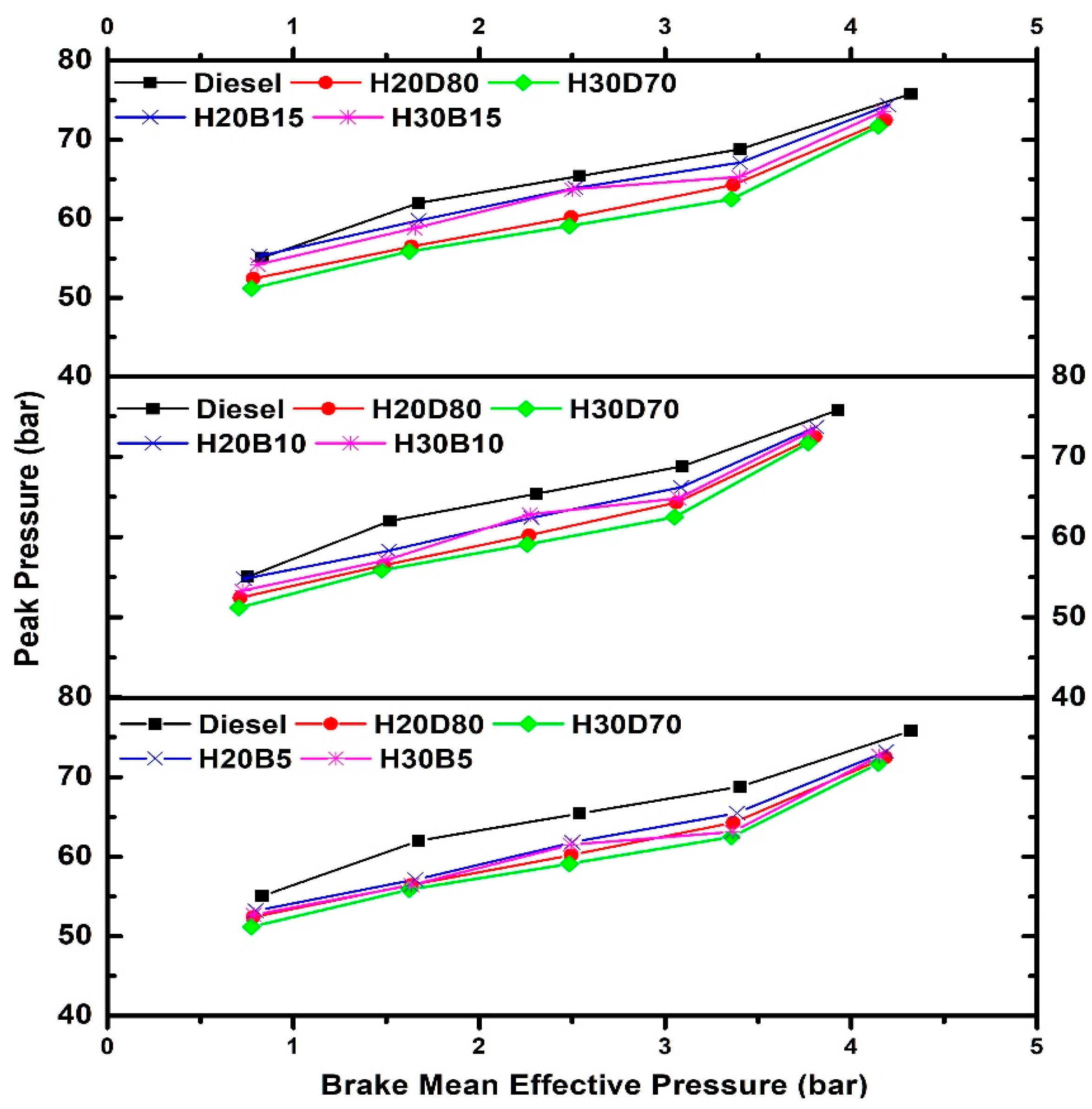
  • With the addition of biodiesel, the engine’s heat release rate increased, and this trend was continued as the proportion of biodiesel rose. Additionally, a rise in the peak in-cylinder pressure was observed.
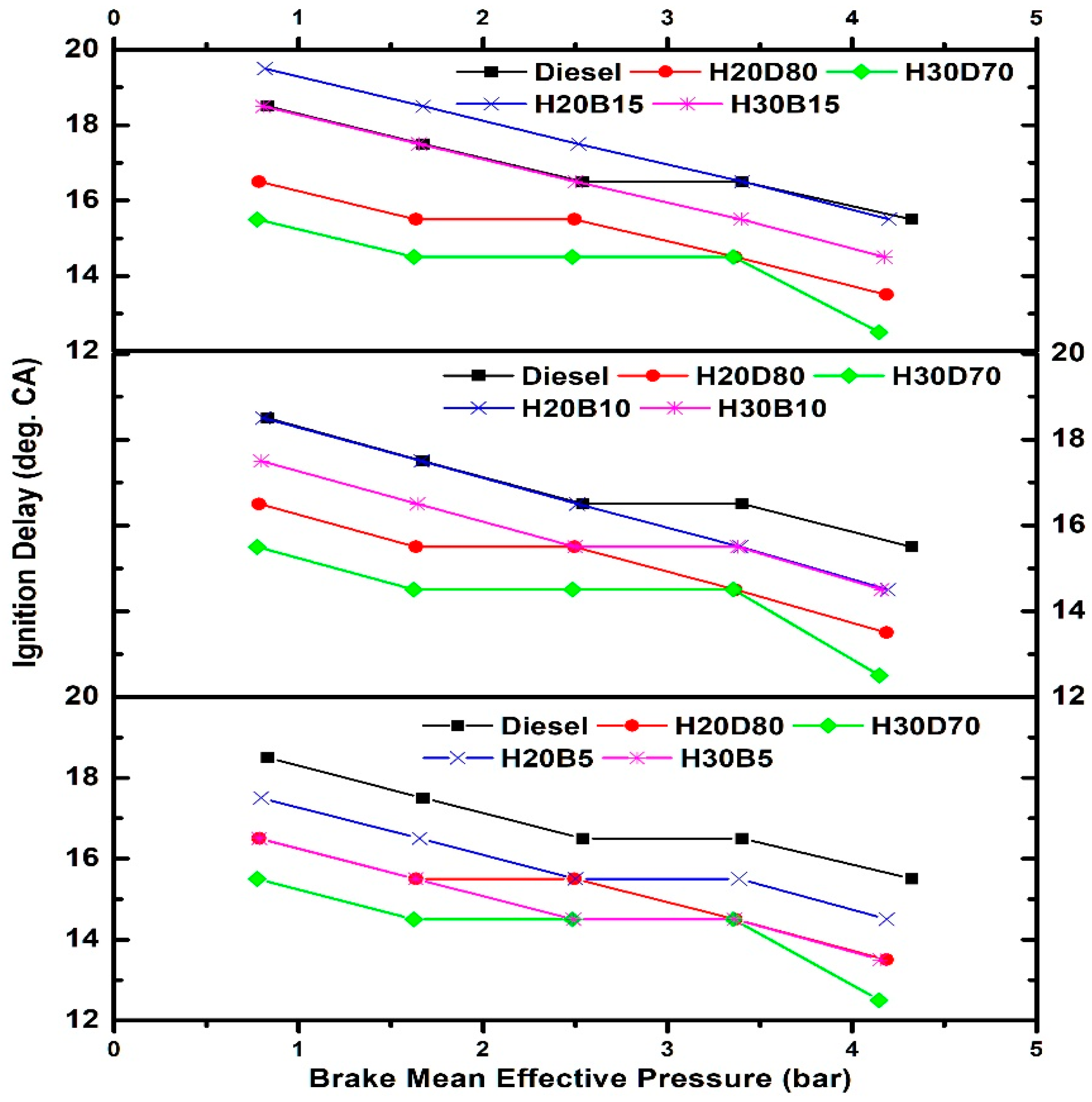
  • In comparison with blends without biodiesel, the ignition delay and combustion duration were longer with the biodiesel mixes.
  • It was discovered that the biodiesel blends had a greater thermal efficiency than H20D80 and H30D70. The thermal efficiency increased with the amount of biodiesel in the blend, although it was still less efficient than diesel. The thermal efficiency was greatest with H20B15.
  • Compared with hydrotreated oil blends without biodiesel, the energy consumption was decreased with biodiesel, but it was still greater than diesel. H20B15 had the lowest energy use when running at full capacity.
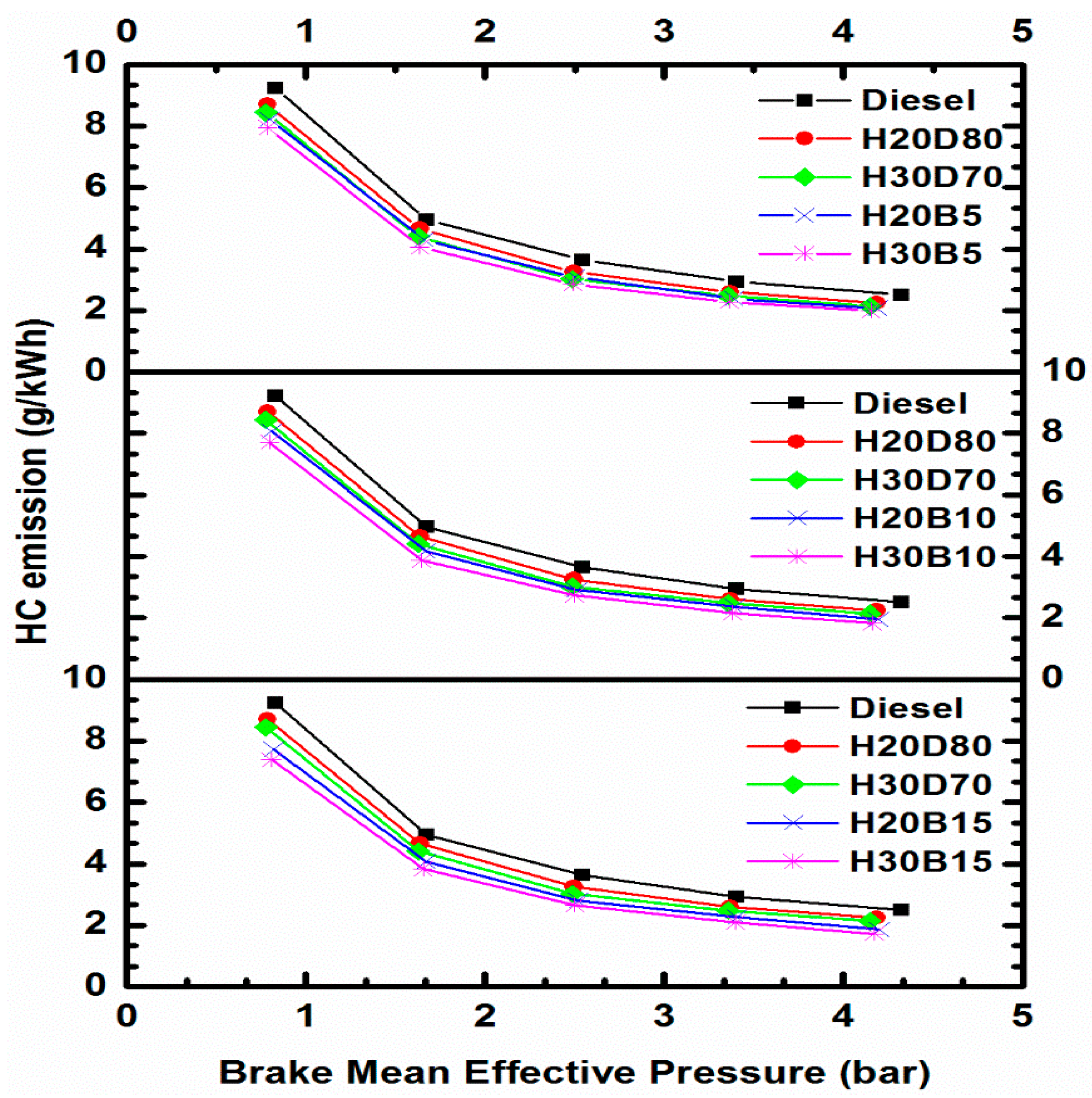
  • With the blend’s biodiesel percentage rising, a drop in HC, CO and smoke emissions was seen. With H30B15, the lowest emissions were noted. H30B15 reduced the HC, CO and smoke emissions at full load by 30%, 23.5% and 21.1%, respectively.
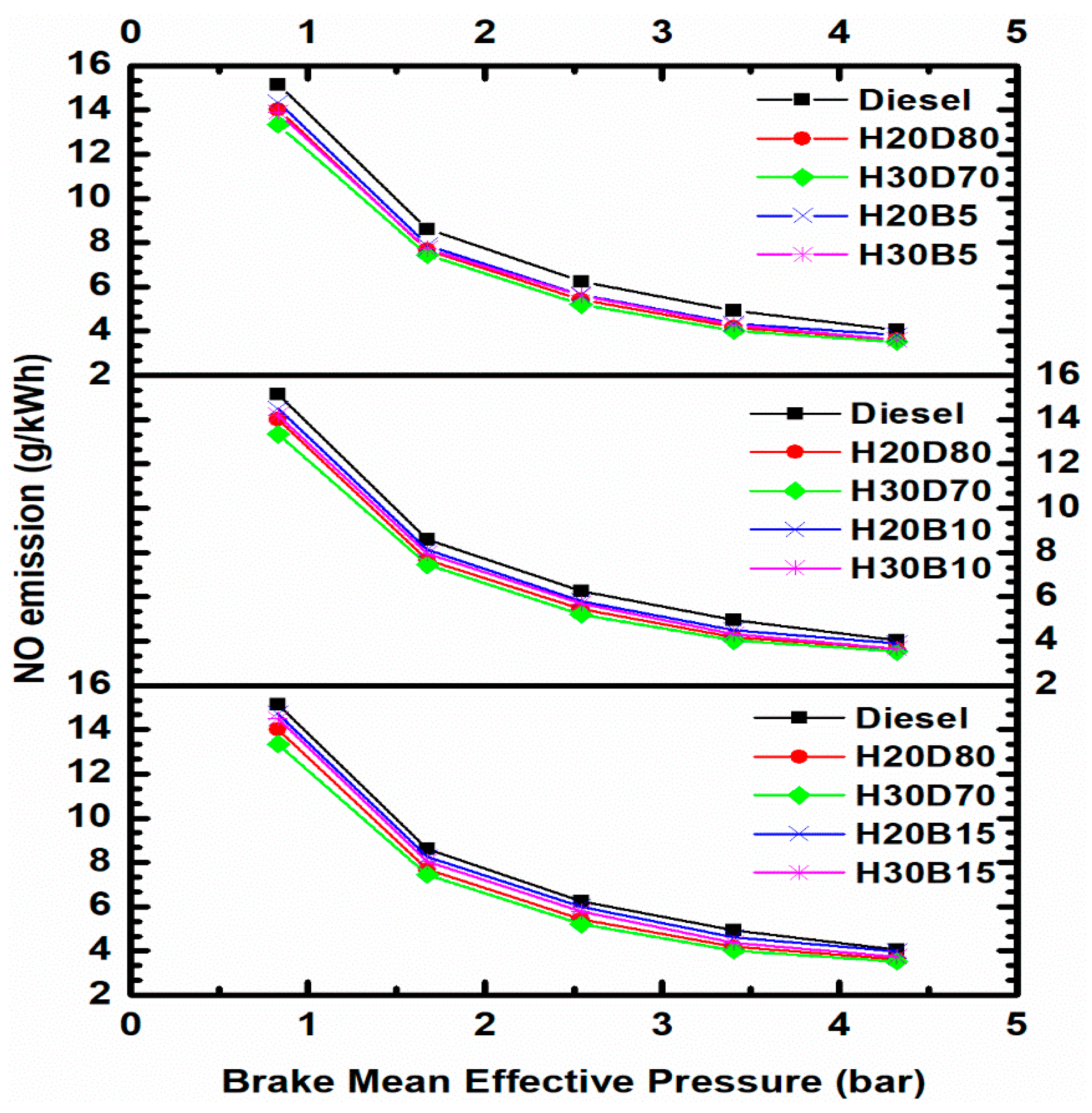
  • The amount of biodiesel in the mix was found to increase the NO emissions, although they were still less than for diesel.
From the results, there is no clarity as to which blend can be considered the best. Hence, fuzzy-logic-based Taguchi optimization was carried out using HVO and biodiesel percentage as the input parameters and BTE, NO and smoke as the output parameters. The best blend from the optimization was found to be H30B15. The confirmation experiment showed that the regulated emission reduction was highest with the blend. However, there was a slight compromise in the thermal efficiency of the engine.
The optimized fuel blend fulfiled the objective of the study, which was to prepare a fuel blend that can be easily used in diesel engines. The use of the proposed blend resulted in lower emissions without modifying the engine. It is difficult to modify those engines that are already in use. Such engines also have no exhaust aftertreatment system; hence, lower emissions due to the fuel itself are cost effective and environmentally friendly. As a future study, modifications in the engine can be explored so that the fuel economy of the engine can be improved, along with even further lowering of the emissions. The shelf-life of the fuel is one aspect that can be studied. Another study can be carried out by doping the blend with different nanoparticles and their effect on engine performance and emission can be analyzed. Lastly, the long-term impact of the fuel blend on the engine parts, especially the injection system and filtration system, can be explored.

Author Contributions

A.S.—formal analysis, investigation, methodology, writing—original draft, writing—review and editing; N.K.—conceptualization, supervision, methodology, writing—review and editing. All authors have read and agreed to the published version of the manuscript.

Funding

This research received no external funding.

Data Availability Statement

Not applicable.

Conflicts of Interest

The authors declare no conflict of interest.

References

  1. Ehsanifar, M.; Tameh, A.A.; Farzadkia, M.; Kalantari, R.R.; Zavareh, M.S.; Nikzaad, H.; Jafari, A.J. Exposure to nanoscale diesel exhaust particles: Oxidative stress, neuroinflammation, anxiety and depression on adult male mice. Ecotoxicol. Environ. Saf. 2019, 168, 338–347. [Google Scholar] [CrossRef] [PubMed]
  2. Lorne, D.; Bouter, A. Biofuels in the Road Transport Sector. IFP Energies Nouvelles. 2021. Available online: https://www.ifpenergiesnouvelles.com/print/pdf/node/1512 (accessed on 19 July 2023).
  3. Aatola, H.; Larmi, M.; Sarjovaara, T.; Mikkonen, S. Hydrotreated Vegetable Oil (HVO) as a Renewable Diesel Fuel: Trade-off between NOx, Particulate Emission, and Fuel Consumption of a Heavy Duty Engine. SAE Int. J. Engines 2008, 1, 1251–1262. [Google Scholar] [CrossRef]
  4. Duda, K.; Wierzbicki, S.; Śmieja, M.; Mikulski, M. Comparison of performance and emissions of a CRDI diesel engine fuelled with biodiesel of different origin. Fuel 2018, 212, 202–222. [Google Scholar] [CrossRef]
  5. Bezergianni, S.; Dimitriadis, A. Comparison between different types of renewable diesel. Renew. Sustain. Energy Rev. 2013, 21, 110–116. [Google Scholar] [CrossRef]
  6. Andersson, J.; Grönkvist, S. Large-scale storage of hydrogen. Int. J. Hydrogen Energy 2019, 44, 11901–11919. [Google Scholar] [CrossRef]
  7. Garraín, D.; Herrera, I.; Lago, C.; Lechón, Y.; Sáez, R. Renewable Diesel Fuel from Processing of Vegetable Oil in Hydrotreatment Units: Theoretical Compliance with European Directive 2009/28/EC and Ongoing Projects in Spain. Smart Grid Renew. Energy 2010, 1, 70–73. [Google Scholar] [CrossRef]
  8. Šimáček, P.; Kubička, D.; Kubičková, I.; Homola, F.; Pospíšil, M.; Chudoba, J. Premium quality renewable diesel fuel by hydroprocessing of sunflower oil. Fuel 2011, 90, 2473–2479. [Google Scholar] [CrossRef]
  9. Huber, G.W.; O’Connor, P.; Corma, A. Processing biomass in conventional oil refineries: Production of high quality diesel by hydrotreating vegetable oils in heavy vacuum oil mixtures. Appl. Catal A Gen. 2007, 329, 120–129. [Google Scholar] [CrossRef]
  10. Kumar, N.; Sonthalia, A.; Koul, R. Optimization of the process parameters for hydrotreating used cooking oil by the taguchi method and fuzzy logic. J. Energy Resour. Technol. Trans. ASME 2020, 142, 123006. [Google Scholar] [CrossRef]
  11. Ratcliff, M.A.; Dane, A.J.; Williams, A.; Ireland, J.; Luecke, J.; McCormick, R.L.; Voorhees, K.J. Diesel Particle Filter and Fuel Effects on Heavy-Duty Diesel Engine Emissions. Environ. Sci. Technol. 2010, 44, 8343–8349. [Google Scholar] [CrossRef]
  12. Hartikka, T.; Kuronen, M.; Kiiski, U. Technical Performance of HVO (Hydrotreated Vegetable Oil) in Diesel Engines; SAE Technical Paper 2012-01-1585; SAE International: Warrendale, PA, USA, 2012. [Google Scholar]
  13. Bortel, I.; Vávra, J.; Takáts, M. Effect of HVO fuel mixtures on emissions and performance of a passenger car size diesel engine. Renew. Energy 2019, 140, 680–691. [Google Scholar] [CrossRef]
  14. Vo, C.; Charoenphonphanich, C.; Karin, P.; Susumu, S.; Hidenori, K. Effects of variable O2 concentrations and injection pressures on the combustion and emissions characteristics of the petro-diesel and hydrotreated vegetable oil-based fuels under the simulated diesel engine condition. J. Energy Inst. 2018, 91, 1071–1084. [Google Scholar] [CrossRef]
  15. Bohl, T.; Smallbone, A.; Tian, G.; Roskilly, A.P. Particulate number and NOx trade-off comparisons between HVO and mineral diesel in HD applications. Fuel 2018, 215, 90–101. [Google Scholar] [CrossRef]
  16. Kuronen, M.; Mikkonen, S.; Aakko, P.; Murtonen, T. Hydrotreated Vegetable Oil as Fuel for Heavy Duty Diesel Engines; SAE Technical Paper 2007-01-4031; SAE International: Warrendale, PA, USA, 2007. [Google Scholar]
  17. Pirjola, L.; Rönkkö, T.; Saukko, E.; Parviainen, H.; Malinen, A.; Alanen, J.; Saveljeff, H. Exhaust emissions of non-road mobile machine: Real-world and laboratory studies with diesel and HVO fuels. Fuel 2017, 202, 154–164. [Google Scholar] [CrossRef]
  18. Bugarski, A.D.; Hummer, J.A.; Vanderslice, S. Effects of hydrotreated vegetable oil on emissions of aerosols and gases from light-duty and medium-duty older technology engines. J. Occup. Environ. Hyg. 2016, 13, 293–302. [Google Scholar] [CrossRef]
  19. Kumar, N.; Sonthalia, A.; Tomar, M.; Koul, R. An Experimental Investigation on spray, performance and emission of hydrotreated waste cooking oil blends in an agricultural engine. Int. J. Engine Res. 2021, 22, 2305–2317. [Google Scholar] [CrossRef]
  20. Cheng, Q.; Tuomo, H.; Kaario, O.T.; Martti, L. Spray dynamics of HVO and EN590 diesel fuels. Fuel 2019, 245, 198–211. [Google Scholar] [CrossRef]
  21. Preuss, J.; Munch, K.; Andersson, M.; Denbratt, I. Comparison of Long-Chain Alcohol Blends, HVO and Diesel on Spray Characteristics, Ignition and Soot Formation; SAE Technical Paper 2019-01-0018; SAE International: Warrendale, PA, USA, 2019. [Google Scholar]
  22. Nylund, N.O.; Erkkilä, K.; Ahtiainen, M.; Murtonen, T.; Saikkonen, P.; Amberla, A.; Aatola, H. Optimized usage of NExBTL renewable diesel fuel: OPTIBIO. 2011. Available online: https://publications.vtt.fi/pdf/tiedotteet/2011/T2604.pdf (accessed on 19 July 2023).
  23. Erkkilä, K.; Nylund, N.O.; Hulkkonen, T.; Tilli, A.; Mikkonen, S.; Saikkonen, P.; Makinen, R.; Amberla, A. Emission performance of paraffinic HVO diesel fuel in heavy duty vehicles; SAE Technical Paper 2011-01-1966; SAE International: Warrendale, PA, USA, 2011. [Google Scholar]
  24. Mäkinen, R.; Nylund, N.; Erkkilä, K.; Saikkonen, P. Bus Fleet Operation on Renewable Paraffinic Diesel Fuel; SAE Technical Paper 2011-01-1965; SAE International: Warrendale, PA, USA, 2011. [Google Scholar]
  25. Sugiyama, K.; Goto, I.; Kitano, K.; Mogi, K.; Honkanen, M. Effects of Hydrotreated Vegetable Oil (HVO) as Renewable Diesel Fuel on Combustion and Exhaust Emissions in Diesel Engine. SAE Int. J. Fuels Lubr. 2011, 5, 205–217. [Google Scholar] [CrossRef]
  26. Wu, Y.; Ferns, J.; Li, H.; Andrews, G. Investigation of combustion and emission performance of hydrogenated vegetable oil (HVO) diesel. SAE Int. J. Fuels Lubr. 2017, 10, 895–903. [Google Scholar] [CrossRef]
  27. Ezzitouni, S.; Soriano, J.A.; Gómez, A.; Armas, O. Impact of injection strategy and GTL fuels on combustion process and performance under diesel engine start. Fuel 2017, 200, 529–544. [Google Scholar] [CrossRef]
  28. Mikulski, M.; Hunicz, J.; Vasudev, A.; Rybak, A.; Gęca, M. Combustion of Hydrotreated Vegetable Oil in a Diesel Engine: Sensitivity to Split Injection Strategy and Exhaust Gas Recirculation. In Proceedings of the ASME 2020 Internal Combustion Engine Division Fall Technical Conference, Virtual, 4–6 November 2020; p. ICEF2020-2936. [Google Scholar]
  29. Liu, D.; Ghafourian, A.; Xu, H. Phenomenology of EGR in a Light Duty Diesel Engine Fuelled with Hydrogenated Vegetable Oil (HVO), Used Vegetable Oil Methyl Ester (UVOME) and Their Blends; SAE Technical Paper 2013-01-1688; SAE International: Warrendale, PA, USA, 2013. [Google Scholar]
  30. Dimitriadis, A.; Seljak, T.; Baškovič, U.Ž.; Dimaratos, A.; Bezergianni, S.; Samaras, Z.; Katrašnik, T. Improving PM-NOx trade-off with paraffinic fuels: A study towards diesel engine optimization with HVO. Fuel 2020, 265, 116921. [Google Scholar] [CrossRef]
  31. Hunicz, J.; Mikulski, M.; Shukla, P.C.; Gęca, M.S. Partially premixed combustion of hydrotreated vegetable oil in a diesel engine: Sensitivity to boost and exhaust gas recirculation. Fuel 2022, 307, 121910. [Google Scholar] [CrossRef]
  32. Lehto, K.; Elonheimo, A.; Häkkinen, K.; Sarjovaara, T.; Larmi, M. Emission Reduction Using Hydrotreated Vegetable Oil (HVO) With Miller Timing and EGR in Diesel Combustion. SAE Int. J. Fuels Lubr. 2011, 5, 218–224. [Google Scholar] [CrossRef]
  33. Hunicz, J.; Krzaczek, P.; Gęca, M.; Rybak, A.; Mikulski, M. Comparative study of combustion and emissions of diesel engine fuelled with FAME and HVO. Combust. Engines 2021, 184, 72–78. [Google Scholar] [CrossRef]
  34. Dobrzyńska, E.; Szewczyńska, M.; Pośniak, M.; Szczotka, A.; Puchałka, B.; Woodburn, J. Exhaust emissions from diesel engines fueled by different blends with the addition of nanomodifiers and hydrotreated vegetable oil HVO. Environ. Pollut. 2020, 259, 113772. [Google Scholar] [CrossRef]
  35. Sonthalia, A. Performance, Emission and Combustion Studies of a Modified Vegetable Oil in a Compression Ignition Engine. Available online: https://shodhganga.inflibnet.ac.in/handle/10603/326348 (accessed on 19 July 2023).
  36. Sidharth; Kumar, N. Performance and emission studies of ternary fuel blends of diesel, biodiesel and octanol. Energy Sources Part A Recover. Util. Environ. Eff. 2020, 42, 2277–2296. [Google Scholar] [CrossRef]
  37. ASTM D1298; Standard Test Method for Density, Relative Density, or API Gravity of Crude Petroleum and Liquid Petroleum Products by Hydrometer Method. ASTM: West Conshohocken, PA, USA, 2017.
  38. ASTM D445; Standard Test Method for Kinematic Viscosity of Transparent and Opaque Liquids (and Calculation of Dynamic Viscosity). ASTM: West Conshohocken, PA, USA, 2017.
  39. ASTM D240; Standard Test Method for Heat of Combustion of Liquid Hydrocarbon Fuels by Bomb Calorimeter. ASTM: West Conshohocken, PA, USA, 2019.
  40. ASTM D93; Standard Test Methods for Flash Point by Pensky-Martens Closed Cup Tester. ASTM: West Conshohocken, PA, USA, 2020.
  41. ASTM D4737; Standard Test Method for Calculated Cetane Index by Four Variable Equation. ASTM: West Conshohocken, PA, USA, 2020.
  42. Soloiu, V.; Duggan, M.; Harp, S.; Vlcek, B.; Williams, D. PFI (port fuel injection) of n-butanol and direct injection of biodiesel to attain LTC (low-temperature combustion) for low-emissions idling in a compression engine. Energy 2013, 52, 143–154. [Google Scholar] [CrossRef]
  43. Heywood, J.B. Internal Combustion Engine Fundamentals; Mc-Graw Hill: New York, NY, USA, 1988. [Google Scholar]
  44. Thiyagarajan, S.; Herfatmanesh, M.R.; Geo, V.E.; Peng, Z. Experimental investigation into the effect of magnetic fuel reforming on diesel combustion and emissions running on wheat germ and pine oil. Fuel Process. Technol. 2019, 186, 116–124. [Google Scholar] [CrossRef]
  45. Karthickeyan, V.; Ashok, B.; Nanthagopal, K.; Thiyagarajan, S.; Geo, V.E. Investigation of novel Pistacia khinjuk biodiesel in DI diesel engine with post combustion capture system. Appl. Therm. Eng. 2019, 159, 113969. [Google Scholar] [CrossRef]
  46. Singh, D.; Subramanian, K.A.; Bal, R.; Singh, S.P.; Badola, R. Combustion and emission characteristics of a light duty diesel engine fueled with hydro-processed renewable diesel. Energy 2018, 154, 498–507. [Google Scholar] [CrossRef]
  47. Boopathi, D.; Thiyagarajan, S.; Edwin Geo, V.; Madhankumar, S.; Gheith, R. Effect of geraniol on performance, emission and combustion characteristics of CI engine fuelled with gutter oil obtained from different sources. Energy 2018, 157, 391–401. [Google Scholar] [CrossRef]
  48. Subramanian, T.; Varuvel, E.G.; Leenus, J.M.; Beddhannan, N. Effect of electrochemical conversion of biofuels using ionization system on CO2 emission mitigation in CI engine along with post-combustion system. Fuel Process. Technol. 2018, 173, 21–29. [Google Scholar] [CrossRef]
  49. Agarwal, A.K.; Dhar, A. Experimental investigations of performance, emission and combustion characteristics of Karanja oil blends fuelled DICI engine. Renew. Energy 2013, 52, 283–291. [Google Scholar] [CrossRef]
  50. Thiyagarajan, S.; Sonthalia, A.; Edwin Geo, V. Effect of electromagnet-based fuel-reforming system on high-viscous and low-viscous biofuel fueled in heavy-duty CI engine. J. Therm. Anal Calorim. 2019, 138, 633–644. [Google Scholar] [CrossRef]
  51. Boopathi, D.; Thiyagarajan, S.; Sonthalia, A.; Parthiban, P.; Devanand, S.; Edwin Geo, V. Effect of methanol fumigation on performance and emission characteristics in a waste cooking oil-fuelled single cylinder CI engine. Energy Sources Part A Recover. Util. Environ. Eff. 2019, 41, 1088–1096. [Google Scholar] [CrossRef]
  52. Chelladurai, P.; Geo, V.E. Experimental Investigation to Study the Effect of Properties of Coconut Oil Biodiesel and Castor Oil Biodiesel and its Blending with Diesel on the Performance in a CI Engine; SAE Technical Paper 2016-28-0145; SAE International: Warrendale, PA, USA, 2016. [Google Scholar]
  53. Alawa, B.; Choudhary, J.; Chakma, S. Discernment of synergism in co-pyrolysis of HDPE and PP waste plastics for production of pyro-oil: Mechanistic investigation with economic analysis and health risk assessment. Process Saf. Environ. Prot. 2023, 169, 107–131. [Google Scholar] [CrossRef]
  54. Yusuf, A.A.; Ampah, J.D.; Veza, I.; Atabani, A.E.; Hoang, A.T.; Nippae, A.; Powoe, M.T.; Afrane, S.; Yusuf, D.A.; Yahuza, I. Investigating the influence of plastic waste oils and acetone blends on diesel engine combustion, pollutants, morphological and size particles: Dehalogenation and catalytic pyrolysis of plastic waste. Energy Conserv. Manag. 2023, 291, 117312. [Google Scholar] [CrossRef]
  55. Lin, C.-Y.; Lin, H.-A. Diesel engine performance and emission characteristics of biodiesel produced by the peroxidation process. Fuel 2006, 85, 298–305. [Google Scholar] [CrossRef]
  56. Kannan, G.R.; Anand, R. Experimental evaluation of DI diesel engine operating with diestrol at varying injection pressure and injection timing. Fuel Process. Technol. 2011, 92, 2252–2263. [Google Scholar] [CrossRef]
  57. Lapuerta, M.; Rodríguez-Fernández, J.; Agudelo, J.R. Diesel particulate emissions from used cooking oil biodiesel. Bioresour. Technol. 2008, 99, 731–740. [Google Scholar] [CrossRef]
  58. Özel, S.; Vural, E.; Binici, M. Optimization of the effect of thermal barrier coating (TBC) on diesel engine performance by Taguchi method. Fuel. 2020, 263, 116537. [Google Scholar] [CrossRef]
  59. Wu, H.; Wu, Z. Using Taguchi method on combustion performance of a diesel engine with diesel/biodiesel blend and port-inducting H2. Appl. Energy 2013, 104, 362–370. [Google Scholar] [CrossRef]
  60. Wu, H.W.; Wu, Z.Y. Combustion characteristics and optimal factors determination with Taguchi method for diesel engines port-injecting hydrogen. Energy 2012, 47, 411–420. [Google Scholar] [CrossRef]
  61. Lin, J.; Wang, K.; Yan, B.; Tarng, Y. Optimization of the electrical discharge machining process based on the Taguchi method with fuzzy logics. J. Mater. Process. Technol. 2000, 102, 48–55. [Google Scholar] [CrossRef]
  62. Roy, S.; Das, A.K.; Banerjee, R. Application of Grey-Taguchi based multi-objective optimization strategy to calibrate the PM-NHC-BSFC trade-off characteristics of a CRDI assisted CNG dual-fuel engine. J. Nat. Gas Sci. Eng. 2014, 21, 524–531. [Google Scholar] [CrossRef]
  63. Pathak, A.; Choudhury, P.K.; Dutta, R.K. Taguchi-Grey Relational Based Multi-Objective Optimization of Process Parameters on The Emission and Fuel Consumption Characteristics of a VCR Petrol Engine. Mater. Today: Proc. 2018, 5, 4702–4710. [Google Scholar] [CrossRef]
  64. Bose, P.K.; Deb, M.; Banerjee, R.; Majumder, A. Multi objective optimization of performance parameters of a single cylinder diesel engine running with hydrogen using a Taguchi-fuzzy based approach. Energy 2013, 63, 375–386. [Google Scholar] [CrossRef]
  65. Kumar Chidambaram, R.; Sonthalia, A.; Poornananadan, G.; Varuvel, E.G.; Subramanian, T. Optimization of compression ratio and injection timing of a diesel engine Fueled with oxygenated blends using fuzzy logic-based Taguchi method. Energy Sources Part A Recover. Util. Environ. Eff. 2021. [Google Scholar] [CrossRef]
Figure 1. Schematic of the experimental setup.
Energies 16 07431 g001
Figure 2. Variation in heat release with biodiesel mixed in blends at full load.
Energies 16 07431 g002
Figure 3. Variation in in-cylinder pressure with biodiesel mixed in the blends at full load.
Energies 16 07431 g003
Figure 4. Variation in peak pressure with biodiesel mixed in the blends.
Energies 16 07431 g004
Figure 5. Variation in ignition delay with biodiesel mixed in the blends.
Energies 16 07431 g005
Figure 6. Variation in combustion duration with biodiesel mixed in the blends.
Energies 16 07431 g006
Figure 7. Variation in CA50 with biodiesel mixed in the blends.
Energies 16 07431 g007
Figure 8. Variation in brake thermal efficiency with biodiesel mixed in the blends.
Energies 16 07431 g008
Figure 9. Variation in brake-specific energy consumption with biodiesel mixed in the blends.
Energies 16 07431 g009
Figure 10. Variation in exhaust gas temperature with biodiesel mixed in the blends.
Energies 16 07431 g010
Figure 11. Variation in unburned hydrocarbon emissions with biodiesel mixed in the blends.
Energies 16 07431 g011
Figure 12. Variation in carbon monoxide emissions with biodiesel mixed in the blends.
Energies 16 07431 g012
Figure 13. Variation in oxides of nitrogen emissions with biodiesel mixed in the blends.
Energies 16 07431 g013
Figure 14. Variation in smoke opacity with biodiesel mixed in the blends.
Energies 16 07431 g014
Figure 15. Membership function of BTE, NO and smoke.
Energies 16 07431 g015
Figure 16. Membership function of MPCI.
Energies 16 07431 g016
Figure 17. Plot of mean MPCI.
Energies 16 07431 g017
Table 1. Properties of diesel and blends of biodiesel, diesel and hydrotreated waste cooking oil.
PropertiesStandardDieselH20D80H30D70H20B5H20B10H20B15H30B5H30B10H30B15
Density @ 15 °C (kg/m3)ASTM D1298 [37]835.07829.68829.1833.02834.46835.89831.29832.72834.15
Kinematic viscosity @ 40 °C (cST)ASTM D445 [38]2.512.592.623.293.443.623.323.473.64
Calorific value (MJ/kg)ASTM D240 [39]42.5742.2942.0842.3542.2842.2242.2742.2142.14
Flash point (°C)ASTM D93 [40]5860.261.1707783737884
Cetane indexASTM D4737 [41]48.7849.9351.050.2851.652.7752.153.1554.17
Table 2. Test engine specification.
SpecificationValue
Rated power3.5 kW
Rated speed1500 rpm
No. of cylinders1
Stroke 4
Displacement661 cc
Stroke length110 mm
Bore diameter87.5 mm
Cooling systemWater cooled
InjectorSolenoid, six-holed
Compression ratio12–18
Table 3. Factors and their levels.
FactorsLevel 1Level 2Level 3Level 4
HVO percentage (%)2030
Biodiesel percentage (%)051015
Table 4. L8 orthogonal array.
Experiment No.HVO Percentage (%)Biodiesel Percentage (%)
E1020
E2030
E3520
E4530
E51020
E61030
E71520
E81530
Table 5. S/N ratio for the output variables and the MPCI.
Experiment No.Biodiesel Percentage (%)HVO Percentage (%)BTE (%)S/N RatioNO (g/kWh)S/N RatioSmokeS/N RatioMPCI
E102029.6729.453.63−11.2055.9−34.950.3653
E203028.9429.233.52−10.9354.1−34.660.4215
E352029.9929.543.82−11.6454−34.650.3716
E453029.7529.473.61−11.1552−34.320.5839
E5102030.5129.693.88−11.7852.8−34.450.4747
E6103030.0929.573.66−11.2750.8−34.120.6535
E7152030.9629.823.98−12.0051−34.150.5732
E8153030.4129.663.72−11.4149.2−33.840.7465
Table 6. Fuzzy rule matrix.
BTE (%)NO (g/kWh)SmokeOutput
SSSVVS
SSMVS
SSLS
SMSVS
SMMS
SMLM
SLSS
SLMM
SLLL
MSSVS
MSMS
MSLM
MMSS
MMMM
MMLL
MLSM
MLML
MLLVL
LSSS
LSMM
LSLL
LMSM
LMML
LMLVL
LLSL
LLMVL
LLLVVL
Table 7. Mean MPCI table.
Process ParameterMPCI
Level 1Level 2Level 3Level 4Max-Min
HVO percentage (%)0.44620.6013 0.1551
Biodiesel percentage (%)0.39340.47780.56410.65990.2655
Mean value of MPCI: 0.5238
Table 8. Results of confirmation experiment.
Optimal Process Parameters
PredictionExperiment
Setting level30% (HVO), 15% (biodiesel)30% (HVO), 15% (biodiesel)
S/N ratio−2.4067−2.3578
Mean MPCI 0.73740.7914
Disclaimer/Publisher’s Note: The statements, opinions and data contained in all publications are solely those of the individual author(s) and contributor(s) and not of MDPI and/or the editor(s). MDPI and/or the editor(s) disclaim responsibility for any injury to people or property resulting from any ideas, methods, instructions or products referred to in the content.

