Article

Feasibility Analysis of Compressed Air Energy Storage in Salt Caverns in the Yunying Area

1
China Energy Digital Technology Group Co., Ltd., Beijing 100044, China
2
Hubei Chuyun Energy Storage Technology Co., Ltd., Xiaogan 432400, China
3
State Key Laboratory of Geomechanics and Geotechnical Engineering, Institute of Rock and Soil Mechanics, Chinese Academy of Sciences, Wuhan 430071, China
*
Author to whom correspondence should be addressed.
Energies 2023, 16(20), 7171; https://doi.org/10.3390/en16207171
Submission received: 1 September 2023 / Revised: 30 September 2023 / Accepted: 7 October 2023 / Published: 20 October 2023
(This article belongs to the Special Issue Advances in the Utilization of Underground Energy and Space)

Abstract

:
With the widespread recognition of underground salt cavern compressed air storage at home and abroad, how to choose and evaluate salt cavern resources has become a key issue in the construction of gas storage. This paper discussed the condition of building power plants, the collection of regional data and salt plant data, and the analysis of stability and tightness. Comprehensive analysis and evaluation methods were put forward from four aspects, including ground comprehensive conditions, regional geological conditions and formation lithology, salt mine characteristics, stability, and tightness of salt caverns. The limit equilibrium theory was applied to establish the limit equilibrium failure mode of salt caverns under operating pressure, and the stability coefficient calculation method of the target salt cavern was determined by combining the mechanical characteristics. Based on the physical and mechanical properties of salt rocks, it was found that salt rocks with enough thickness around the salt cavity could be used as sealing rings to ensure the tightness of the salt cavern. Combined with the field water sealing test, the tightness of the target salt cavern is verified. This method has been applied to the salt cavern screening and evaluation of a 300 MW compressed air energy storage power plant project in Yingcheng, Hubei Province, and remarkable results have been obtained, indicating the rationality of the method.

1. Introduction

CAES is an energy system that uses compressed air as a carrier to achieve energy storage and utilization. When storing energy, electrical or mechanical energy drives the compressor to draw air from the environment, compress it to a high-pressure state, and store it in the storage device. During the process, electrical or mechanical energy is converted into internal and potential energy of compressed air. When releasing energy, the compressed air stored in the storage device enters the air turbine to expand and work to generate electricity, in which the internal and potential energy contained in the compressed air is reconverted into electrical or mechanical energy.
The traditional gas power cycle uses natural gas mixed with compressed air in the heat absorption process to raise the inlet temperature of the gas turbine. Learning from the gas power cycle, a burner is set up in front of the expander of the CAES system, and a fuel such as natural gas is used to mix and combust with compressed air in order to raise the air turbine expander inlet temperature. This mixed combustion of fossil fuels and compressed air is adopted to achieve CAES. This kind of technology route is called a supplementary fired CAES system. Supplementary fired CAES has the advantages of simple structure, high technical maturity, reliable equipment operation, low investment cost, long service life, and fast response characteristics similar to gas power stations. However, in the context of developing green energy and controlling carbon emissions, the carbon emission of supplementary fired CAES has become one of its biggest drawbacks.
Non-supplementary fired CAES mainly includes adiabatic, isothermal, and composite forms. Adiabatic CAES is divided into high-temperature adiabatic CAES and medium-temperature adiabatic CAES. There are more kinds of composite CAES systems, which can be diversified and adjusted according to the needs of the theoretical research or engineering applications. A composite CAES system has a strong multi-energy storage and multi-energy supply capacity. It can also realize the storage, conversion, and utilization of various forms of energy, meet the needs of different forms of energy use, and improve the comprehensive energy utilization efficiency of the system.
In addition to CAES, common energy storage technologies also include pumped storage power plants, electrochemical energy storage, hydrogen energy storage, and so on. In order to carry out a cost analysis of different energy storage technologies, this paper analyzes them from five aspects: cost, overall benefit, life cycle, advantages, and disadvantages. Based on the status of built projects and online survey data, the cost and performance prediction levels of different types of energy storage technologies are summarized in Table 1. It can be seen from the analysis that CAES technology has significant advantages and will occupy an important position in long-term large-scale energy storage technology.
In order to pursue large-scale and efficient compressed air energy storage (CAES), geological bodies with certain scale cavities formed during natural or artificial mining are usually used as CAES devices, such as water-bearing rock formations, artificially excavated chambers, salt caverns with solution mining, abandoned coal mines and underground depleted oil and gas reservoirs. The cost of constructing a geological body for gas storage is one of the most important factors considered in the construction of CAES power plants. In areas rich in salt mining resources, using salt caverns after service as CAES can save the cost of cavern construction. Salt rocks have low permeability and great creep ability, which can ensure the stability and tightness of the storage cavern. In addition, they have more stable mechanical properties and characteristics of damage self-recovery [1], so they can adapt to the periodic changes in storage pressure during the operation of CAES reservoirs. Therefore, it is widely recognized to use underground salt caverns to build CAES at home and abroad.
The Yunying area of Hubei Province is known as the salt sea of the anointed capital. Since it started to use the method of solution mining in 1969, more than 100 pairs of salt wells have been constructed, producing nearly more than 30 million tons of salt and forming more than 100 underground solution cavities. In order to rationally utilize salt cavern resources and promote new energy consumption in surrounding areas, the 300 MW CAES power plant project in Yingcheng, Hubei Province 1 (Figure 1) is proposed to select a suitable underground salt cavern solution cavity from the rich salt cavern resources in the Yunying area of Hubei Province as a CAES reservoir. It recommends building the first set of major technology development and demonstration projects of a 300 MW/1500 MWh class non-combustion CAES [2]. After the completion of the project, it will be the first in the world in the field of CAES in terms of single-machine power, energy storage scale, and conversion efficiency.
The project constructs a 300 MW (1500 MWh) non-supplementary fired CAES power generation system. The compression system adopts eight large turbine compressor units arranged in double rows and four compressor units in series in a single row. The comprehensive polytropic efficiency is about 90%. The air turbine system adopts a double-reheat single-shaft 300 MW turbine. For the project, it adopts a high-pressure hot water storage medium-temperature adiabatic compression scheme. The system will run for 8 h with grid low power compression and 5 h with grid peak power generation. The annual utilization hours are about 1660 h.
The compressed air is stored in the underground salt cavern. According to the requirements of power generation capacity and duration, combined with the information collected from the salt cavern in the Yunying area, the pressure range of the salt cavern roof is considered to be 7.0~9.0 MPa, the volume of the salt cavern cavity is 650,000 m2, and the depth of the salt well is about 500 m. Taking the underground salt cavern cavity in the Yunying area as an example, this paper further analyzes the feasibility of the salt cavern as a compressed air storage reservoir in terms of ground conditions, geological structure, cavity characteristics, cavity stability, and cavity sealing. The feasibility of salt caverns as compressed air storage reservoirs is further analyzed in terms of ground conditions, geological structure, cavity characteristics, cavity stability, and cavity tightness.

2. Comprehensive Ground Conditions

Focusing on the ground working conditions of underground salt cavern energy storage, numerous scholars have conducted research on the site selection of gas storage. Jiang et al. [3] proposed the ground facility layout and traffic evaluation method. Li et al. [4] put forward that natural gas storage should avoid some areas with unsuitable human environments. Demirel et al. [5] proposed to select an underground gas storage location by using a group decision integral method under a fuzzy environment in consideration of cost, time, availability, risk, social factors, and environmental factors of storage site selection. Zeng et al. [6] recommended that the comprehensive ground factors including population and building density, structure types, and distance from the concentration of users should be considered when selecting the site. Zheng et al. [7] proposed that ground conditions such as the location of salt mines, ground buildings, water sources, and brine sales and mineral rights ownership should be considered when selecting the site for salt cavern natural gas storage. Few studies have been conducted specifically on the ground conditions of salt cavern compressed air storage. Generally speaking, compressed air storage will not endanger the human environment due to gas leakage, and the comprehensive ground conditions should focus on the purpose of CAES power plant construction and its requirements for the ground environment. Therefore, the following ground conditions should be considered in the selection of salt cavern compressed air storage:
(1)
Requirements for the construction of the CAES power plant: the power plant site should not be too far from the gas storage, and it should have a relatively flat site or with land leveling conditions. Its geometric plane area should meet the requirements for the construction of the plant. It should avoid basic agricultural land and ecological red lines, residential areas, and a large number of demolitions. Important infrastructures within a 1 km range should be avoided, including high-speed railroads, airports, military zones, and gas stations.
(2)
Traffic conditions: the provincial roads and above should be available in the surrounding of proposed gas storage and power plants to basically meet the requirements of large equipment transportation.
(3)
Water and electricity supply conditions: water supply conditions and basic industrial electricity access conditions should be provided.
(4)
Power access conditions: it should have access to 110 kV or 220 kV substations within 50 km or have the conditions for building or expanding substations.
Salt plants are gathered in the Yunying area of Hubei Province, which has good economic development, and satisfies the conditions of traffic, water supply, and electricity access. It is only needed to choose a place suitable for building power plants and obtain permission to use a salt mine. Yingcheng 300 WM level compressed air storage reservoir selected the Jiuda salt plant X5–X6 and X7–X8 salt caverns to build the reservoir, which is located in Sili Shed Street, Yingcheng City. It is about 3 km away from the Fuhe River on the east side so there is sufficient water supply and it is easy to use. It is about 2.3 km away from G347 National Road on the south side, about 3.8 km away from Handan Line, and about 0.5 km away from 003 Township Road on the west side, with convenient railway and highway traffic and flat terrain. The area is well connected to electricity and there is no important infrastructure in the surrounding area.
At the same time, there is a relatively flat site around the Jiuda X5–X6 and X7–X8 salt caverns. The available site is about 470 m long from east to west, about 300 m wide from north to south, and the available area is about 0.141 km2. The range is not subject to restrictions such as basic farmland, which is convenient to set ground field house. It has comprehensive ground conditions that should be considered when selecting the site for compressed air storage in salt caverns.

3. Regional Geological Conditions and Stratigraphic Lithology

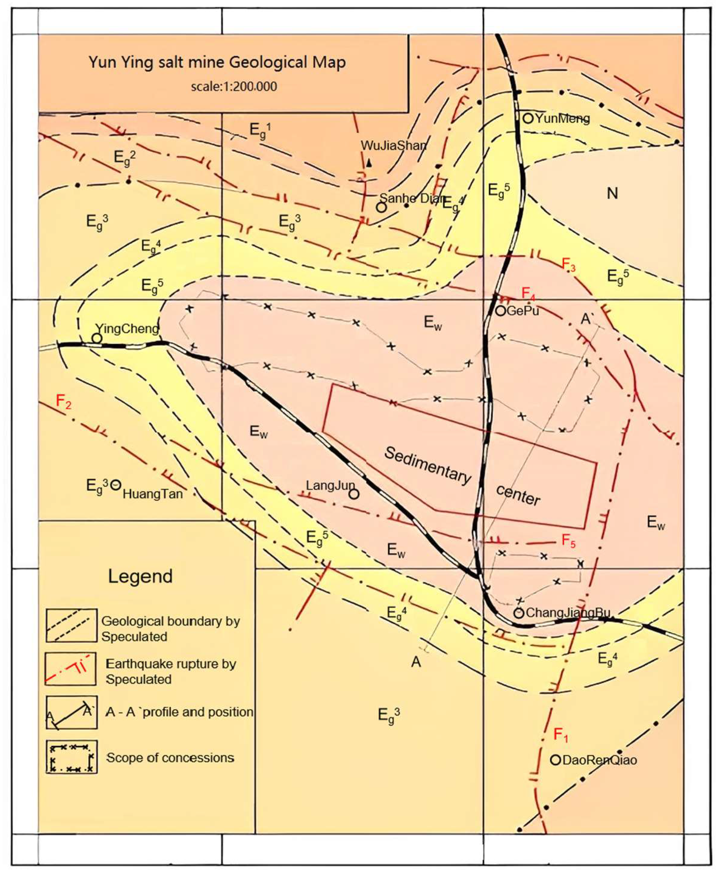
3.1. Regional Geological Conditions

Regional geological conditions have an important influence on the site selection and overall stability analysis of compressed air storage in salt caverns. The Pingdingshan gas storage [8], Jintan gas storage [9], and Huaian gas storage [7] in Henan were basically built in salt rock sedimentary areas with simple tectonics, gentle stratigraphy, small historical earthquakes, and undeveloped or less developed faults.
The Hubei Yunying Basin is located in the northeastern part of the Jianghan Depression, which is an inland salt lake depression formed during the Cretaceous to Paleozoic period. The northern boundary is unconformably overlain by the Aurignacian to Cambrian system and the Yuan Ancient boundary, forming a slope inclined to the southwest. It adjoins the low protrusion of Longsai Lake in the south, bounded by the Soap City Fault in the west and the Hanchuan protrusion in the east. It is a skip-shaped depression basin controlled by the fracture, with a gentle north and steep south, covering an area of 2700 km2. The deposition center of Yunying Basin is within the range of Yingcheng-GePutan-Daorenqiao, and the salt mining area of Yingcheng is located in the middle and western part of the Yunying Depression.
Fractures in the Yunying Basin are relatively developed, and most of them are basement fractures, which form the general framework of the Yunying Basin. The primary fractures form the basic shape and scale of the depressions and control the sedimentary characteristics of the primary revolutions, which means the distribution of the Cretaceous-Paleocene. The secondary fractures control the overall sedimentary construction of salt mines and the lithology and petrographic distribution of salt-bearing strata. The fractures in the Yunying Basin are mainly developed in the subordinate formations of the Cretaceous—Paleoproterozoic Pantai Mountain Group, Baisakou Group, and Paste Salt Group, without destructive effect on salt deposits. The stratigraphic structure of the Paleocene where the salt deposits are located is simple, and the dip angle of the strata does not vary much. The geological map of the bedrock of the Yunying salt mine is shown in Figure 2. No faults are found beyond 20 km from the Jiuda salt plant.
According to the Distribution of Strong Earthquake Epicenters in Eastern China and Collection and Research of Earthquake Historical Materials in Hubei Province, there are 26 earthquakes with written records of 4.75 magnitude (intensity of 6 degrees) or higher in Hubei Province, which are generally of low magnitude and belong to the weak earthquake area. According to the statistics, there were 41 earthquakes in the salt mining area of Yunying and its periphery (Anlu, Yunmeng, Yingcheng, Xiaonan, Hanchuan, and Jingshan) during the 1676 years from 309 to 1985 AD, all of which were weak earthquakes. Eight earthquakes occurred from 1960 to 1985, with the strongest magnitude of 3.5 and the weakest magnitude of 1.2, and no moderately strong earthquakes occurred. The only earthquake outside the area that affected the region was the 30 May 1603 Zhongxiang 5 magnitude earthquake (center intensity of 6 degrees). The Yunying salt mine area belongs to the 6-degree zone of Hubei Province earthquake intensity zoning, and there are few historical earthquakes with small magnitudes.

3.2. Strata Lithology

According to the strata classification of mine areas by various geological departments, the strata of mine areas from bottom to top are Upper Mesozoic Cretaceous Public Security Village Formation (K2g), Cenozoic Paleogene Yuntaishan Formation (Ey), Baishakou Formation (Eb), Gypsum Salt Formation (Eg), Wenfengta Formation (Ew), Duodashi Formation (N2d, partial loss), and the Quaternary system (Q), see Table 2. The salt formation is a set of gray and ochre mudstone, siltstone, mud gypsum, hard gypsum, calcium mannite, and other salt rocks, buried at a depth of 200–400 m. The thickness of the salt section controlled by drilling is 348.72–554.76 m. The stratigraphy is an unequal-thickness interbedded structure composed of salt layers and interlayers, and some of the salt groups are densely interbedded with a small and gentle dip.

4. Analysis of Salt Mine Characteristics

4.1. Screening Principles and Standards of Existing Salt Cavern

The site selection principle of the existing salt cavern compressed air storage mainly considers stability and tightness. The stability requirement is to ensure the safety and stability of existing salt caverns and to prevent geological disasters such as roof collapse and sidewall panels. It is closely related to the buried depth and internal pressure of salt caverns, and a certain buried depth needs to be combined with a certain safety pressure to ensure its stability [11,12]. The sealing performance of salt caverns is mainly based on the great low permeability and low porosity of salt rock. Salt rock around the whole salt cavern can be used as a seal ring to ensure the tightness of salt caverns. Therefore, a single well with a clear cavity boundary or a horizontal well cavity is preferred as a site of salt cavern CAES power plants. The cavity with a connected cavity and unclear boundary but controllable boundary can also be used as the site of CAES power plants. It is not recommended to select the following salt caverns for CAES: the top of a salt cavern that is completely mined, a cavern with cascading mining layers leading to cascading different strata, and an abandoned old cavern (which has the possibility of top plate mining damage).
According to the functional requirements of salt cavern CAES and the current mining situation of Yunying salt mine, the salt cavern that can be selected for reconstruction of CAES must have the following characteristics: independent horizontal butted well (as shown in Figure 3) or independent fracturing communicated well (as shown in Figure 4) or horizontal butted well with two pairs of well sets in tandem, no large buildings on the ground around the salt well, and the salt cavern roof buried more than 500 m deep.
In the cavern construction of a horizontal butted well (as shown in Figure 3), a vertical well is drilled first, and then a horizontal well (or directional well) is drilled to connect with the bottom of the vertical well to form the initial dissolution cavity channel. When the distance between the clear water injection point and the brine discharge point remains unchanged throughout the process, there is a “dissolution zone with constant distance”, that is, a “horizontal well + vertical well” cavern construction with solution mining.
The two-well hydraulic fracturing cavity construction technology (see Figure 4) is to arrange two vertical wells with a certain distance in the same depth salt layer, and then carry out fracturing operations on the target salt layer. The arrows in Figure 4 indicate the direction of water flow.The hydraulic fractures caused by the operation expand in the horizontal direction in the formation until the bottoms of the two target wells are connected, forming a water-soluble mining channel for fluid migration and dissolution. High-pressure fresh water is injected through one well, passes through the fracture formed by hydraulic fracturing, dissolves the salt rock around the fracture, and flows out from the other well; thus forming a two-well hydraulic fracturing cavity with solution mining. Due to the complexity of geological conditions, fracturing connectivity has certain requirements for geological conditions, that is, the fractures are more inclined to expand along a certain weak surface or layer. If there is no natural weak surface in the selected fractured formation, it is necessary to create artificial fractures and ensure their expansion along a certain direction.
Since the use of the drilling solution mining method in 1969, the salt mines in the Yunying area have been mined for more than 50 years, and more than 100 old underground cavities have been formed. The modes of one injection and one production pair well connection are generally directional horizontal well connection and fracturing connection. The Yunying salt mining layer from top to bottom is divided into the K1 salt group, the K2 salt group, the K10 salt group, and a total of ten salt groups. According to the mining conditions of salt groups, they can be divided into four mining sections: the K1 mining layer, the K2 mining layer, the K3 mining layer, and the K4 mining layer. The K1 mining layer is mainly the K2 salt group, the K2 mining layer is mainly the K4/K5 group, the K3 mining layer is mainly the K8 group, and the K4 mining layer is mainly the K10 salt group. The division of mining layers of the Yunying salt mine is shown in Table 3. The data in the table of mining layers of the Yunying salt mine mainly come from the wells: KK2, CX76, and ZK1011, completed by the salt plant during the salt mine data survey.
The working group investigated four salt masters in the Yunying area, which are Hubei Shuanghuan Chemical Group Co., Ltd. (Xiaogan, China), Zhongyan Yangtze River Salt Chemical Co., Ltd., Xiaogan Guangyan Huayuan Salt Co., Ltd. (Xiaogan, China), and Jiuda (Yingcheng) Salt Mine Co., Ltd. (Xiaogan, China). The working group collected a large number of salt well data and taking various factors into account including the time of well construction, service life, the current status of the salt well, the buried depth of the top plate, salt production volume, well group dissolution volume, well group cavity volume, production layer connectivity, well group connectivity, pair of well connectivity method, ground comprehensive conditions, and other aspects. The dissolution volume of a well group refers to the cavity volume that can store brine within the dissolution range of the well group, and the value is the ratio of salt production weight to rock salt density. Well group cavity volume refers to the cavity volume of a large area connected in the upper part of a well group within the dissolution range, which can store solid waste or gas. It can be estimated according to the working experience in the Yingcheng area.
The salt wells belonging to the salt plant were analyzed one by one according to the above-considered indicators. The old wells that had been blocked, the connected wells in the mining layer, the main wells of the salt plant, the wells with small volume or shallow buried depth, and the wells with collapse or buildings on the ground are excluded. Based on the characteristics of CAES salt caverns, it is preferred to select wells X5–X6 and X7–X8 of the Jiuda Salt Mine (Yingcheng) Co., Ltd., Yingcheng, China, (hereinafter referred to as “Jiuda Salt Mine”) as CAES salt caverns.
The Jiuda Salt Mine site is bound on the north by the G347 National Highway, on the north side by Hejiawan, on the east side by Xiaopeng Village and Dapengwan, and on the west side by the logistics and petrochemical petrol station. The X5–X6 and X7–X8 salt caverns of Jiuda are all within the site. The X6 wellhead is located on the north-west side of the site, the X5 wellhead is on the south-west side, and the X7 and X8 wellheads are on the south-east side. The available site of the plant site is about 470 m long from east to west, 300 m wide from north to south, and the available area is about 14.10 hm2. Four old wells are distributed as shown in Figure 5.
The X5–X6 and X7–X8 production salt wells are connected by fracturing, and the horizontal distance between the two old wells is about 120 m, and the distance between the well groups is about 270 m. The boundary of salt caverns formed by leaching for nearly 30 years is clear and controllable, and the distance between the safety pillars of the two salt caverns should be more than 100 m. The total volume of salt mining is 1.08 million square meters, and the top plate of the salt caverns is buried deeper. There are great ground working conditions, which is convenient for the arrangement of the ground plant. X5–X6 and X7–X8 salt wells leaching investigation is shown in Table 4 below.

4.2. Characteristics of Rock Salt Layer

According to the previous regional data, nearby drilling data, and new drilling survey well data, the strata encountered in drilling from top to bottom are Quaternary (Q); Paleoproterozoic Marl Formation (Eyn3), Upper Sulfate Section (Eyn24 + 5), and Salt Rock Section (Eyn23). The salt-bearing strata are located in the Paleoproterozoic Saltstone Section (Eyn23), which is not drilled through, with a buried depth of 388.90~700.18 m and an apparent thickness of 311.28 m. The light gray, light gray-white, and white salt rock and light gray mudstone are interbedded with unequal thickness. The salt layer interval is brownish-red mudstone interspersed with light gray, interspersed with a large number of gypsum clumps and glauberite grains. The rock types are mainly chloride rocks, sulfate rocks, and mud rocks, which belong to the terrestrial clastic sediment~chemical sedimentary phase. The mineral types of the salt-bearing section are mainly the following five types: rock salt (NaCl), calcium glauberite [CaNa2(SO4)2], gypsum (CaSO4), anhydrous glauber (Na2SO4), and detritus. The stratigraphic structure is simple, and the dip angle of the strata does not vary much, ranging from 1° to 3°. Some of the salt-bearing strata are cored as shown in Figure 6.
The thickness of the salt group is 155.14–194.46 m, with an average thickness of 176.48 m. The thickness of the salt layer is 104.50–150.14 m, with an average thickness of 100.36 m and an ore content of 62.94–77.21%. The brine withdrawal in the Yunying salt mine has been conducted by solution mining method for more than 30 years, which proves that the salt ore has good solubility.
The salt layer and the intercalated (rock) layer contain two soluble minerals, rock salt and calcium glauberite, whose main soluble chemical composition component is NaCl, followed by Na2SO4 and part of CaSO4 dissolved with it. The solubility of the salt group in the study area is 60.59–62.94% according to theoretical calculation. The solubility rate predicted according to brine composition is 57.49–60.02%, which is 2–3% lower than the theoretical calculation.

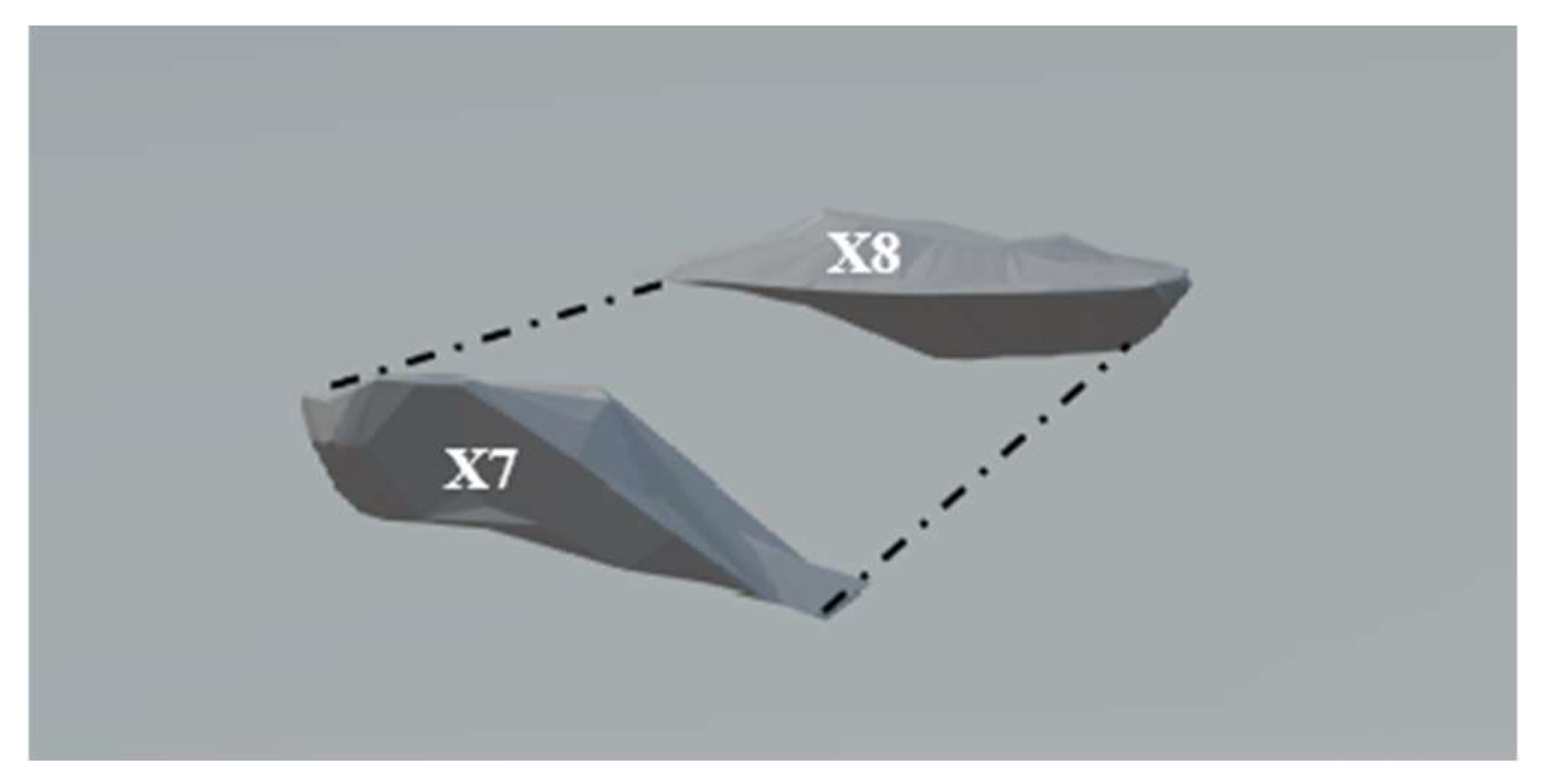
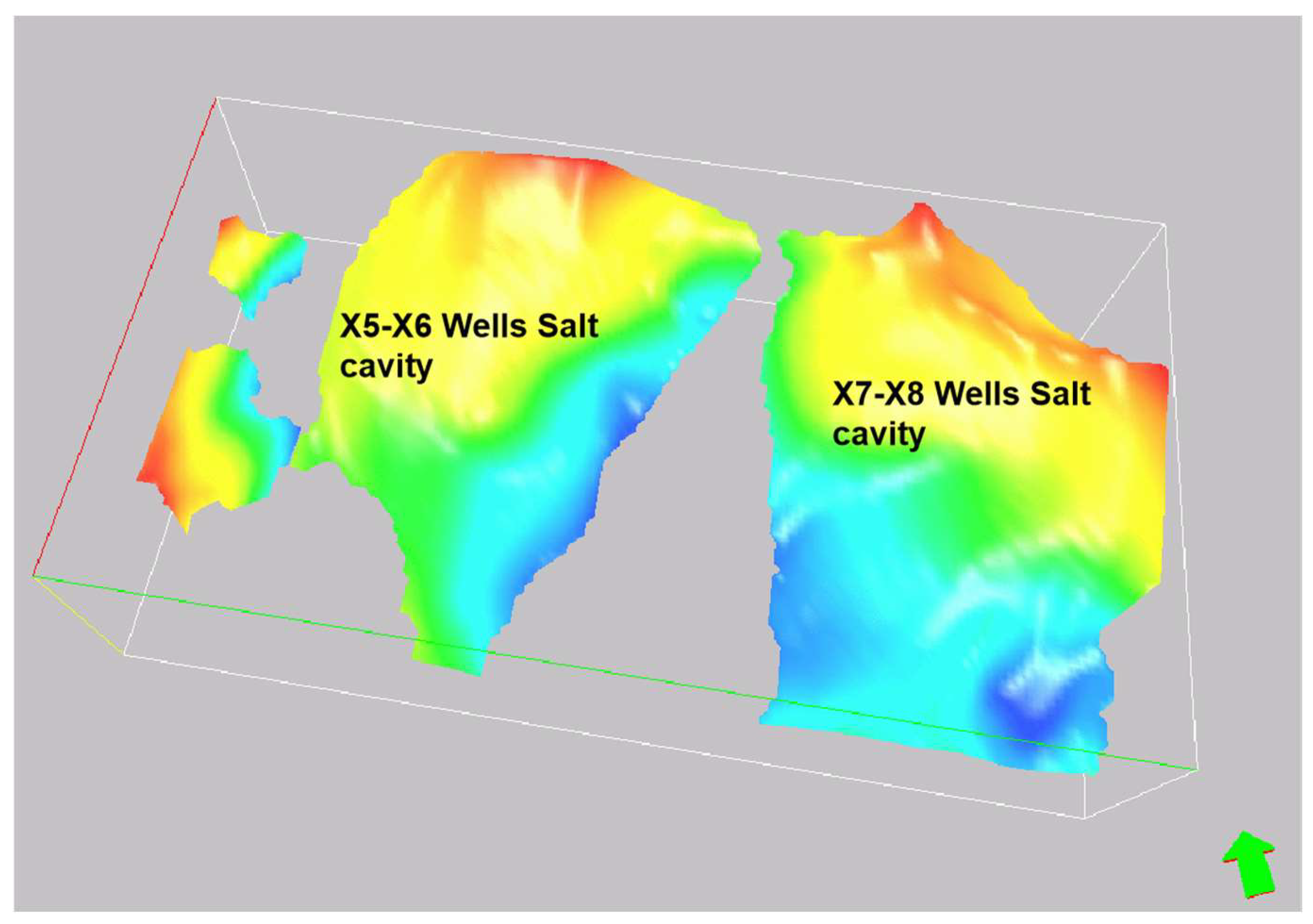
4.3. Salt Cavern Volume Estimation

The volume of the effective cavity of a salt cavern is related to the content of soluble and insoluble matter in the rock salt layer. The higher the soluble content and the lower the insoluble content, the larger the effective cavity volume of the salt cavern is. In addition, the larger the thickness of the insoluble interlayer, the larger the space occupied by sediment at the bottom of the salt cavity is, and the smaller the volume of the salt cavern is. In order to quantitatively calculate the effective volume of a cavity from the theoretical perspective, Zheng Yali et al. [7] proposed a method for estimating the effective volume of a single cavity, considering the influence of insoluble matter content and its accumulation coefficient. A prediction model of the pore volume of the insoluble sediments was established, and the theoretical equations of the mining space of salt cavern and the volume of the brine that can be discharged from the insoluble sediments were proposed [13].
The X5 and X6 wells of the Jiuda salt plant were put into operation in 1989 and stopped in 2017, with a cumulative salt withdrawal volume of 1.84 million tons. The X7 and X8 wells were put into operation in 1994 and stopped in 2016, with a cumulative salt withdrawal volume of 1.76 million tons. Based on the current salt production statistics and calculations, the well group solution cavity volumes are 836,000 and 801,000 m2, respectively. According to the method proposed by Zheng Yali, the effective volumes of salt cavities were calculated as 391,200 and 374,900 m2, respectively. The total effective volume was 766,100 m2, of which the insoluble content was 38% and the accumulation coefficient was predicted to be 1.4. According to the method proposed by Chen Xiaoyuan, the effective volumes of salt cavities were calculated as 445,800 and 427,200 m2, respectively, and the total effective volume was 873,000 m2, of which the proportion of insoluble matter was 0.38, and the predicted coefficient of fragmentation and swelling is 1.7. The percentage change of the total volume calculated by the two calculation methods is 12%. According to the work experience summarized in the Yingcheng area over the years, the cavity volume of the well group can be estimated based on the salt withdrawal volume and volume rate estimation. It can be calculated by the formula V empty = withdrawal salt volume × volume rate. The value of the volume rate is related to the ratio of the interlayer in the formation, the grade of the salt layer, and the expansion coefficient of the insoluble matter. The value is different in different areas. A value of 0.25~0.3 is recommended for the Yingcheng area, and the effective volume of two cavities is calculated to be 552,000 m2 and 528,000 m2, respectively, with a total volume of 1.08 million square meters. It meets the construction scale requirements of the salt cavern CAES.
In order to figure out the distribution characteristics of two pairs of salt cavities, sonar is used to measure the cavity, and the 3D display of the cavities is shown in Figure 7 and Figure 8. The measurement results are shown in Table 5.
Due to the limited detection capability of sonar and the irregular morphology of the cavity, some areas are obscured and sediment and brine are filled. It leads to the range measured by sonar being only part of the space of the cavity. The total volume of the salt cavity measured by sonar is 220,000 m2, which is mainly concentrated near the wellhead. The results of sonar measurement are mainly used to detect the buried depth of the top plate near the old wellbore, and the measured volume of the salt cavern cannot represent its total volume.
A 3D seismic cavity measurement was carried out to further learn the fugacity characteristics of the salt cavity. According to multi-attribute seismic analysis data combined with audio geomagnetic inversion results, depth calibration was finished with data of well washing and cavity measurement with sonar. Comprehensive interpretations of the detection results were obtained based on the previous salt withdrawal volume and the results are shown in Table 6. The 3D display of the underground salt cavity is shown in Figure 9. The arrow in Figure 9 points to the north. In Figure 9, the color gradually changes from red to blue, indicating that the thickness of the salt cavity changes from thick to thin. The total volume of the salt cavity boundary measured by 3D seismic cavity measurement is 1.58 million square meters. The cavity volumes measured by this method all meet the cavity volume requirements of CAES in salt caverns.
From the 3D morphological maps of the salt cavern by sonar and 3D seismic caverns measurement, the cavern is deeply buried on the south side, shallowly buried on the north side, with partial solution in the northeast direction.

4.4. Buried Depth and Operating Pressure Estimation of Salt Cavern

Under the condition of ensuring the stability of the salt cavern as gas storage, the buried depth of the salt cavern determines the maximum and minimum operating pressure during gas injection and production. If the maximum operating pressure is too large and exceeds the fracture pressure of the overlying rock layer, the overall stability of the salt cavern will be destroyed. If the minimum operating pressure is too small, the sheet wall will be destroyed in the salt cavern and the creep inside will be accelerated. To address the issue of salt cavern operating pressure, the author investigated the maximum operating pressure of salt cavern gas storage in foreign countries, which is generally 1.5–1.7 MPa/100 m [12]. Canadian standard Z341.2–10 [14] specifies that the maximum internal pressure of salt cavern gas storage should not exceed 80% of the rupture pressure of overlying formation, and if the data are not available, the pressure gradient should not exceed 1.81 MPa/100 m. Zhang et al. [15] proposed the use of stress path analysis to determine the maximum operating pressure and the minimum operating pressure. The maximum operating pressure can be determined when the stress path reaches the tensile failure criterion, and the minimum operating pressure can be determined when the stress path is lower than the shear failure envelope. Fu [16] proposed the minimum operating pressure of a salt cavern under the condition that the shrinkage rate of the salt cavern is less than 30% by digital simulation. The buried depth of the Jintan salt cavern gas storage roof is about 1010 m, the design of the maximum operating pressure is 17 MPa, and the minimum operating pressure is 7 MPa. There is no mature engineering example for salt cavern CAES in the Yunying area.
The minimum buried depth of the top of the cavity near the old wellbore of the X5–X6 pair of wells and X7–X8 pair of wells measured by sonar is 500 m, and the minimum buried depth of the top boundary of the cavity measured by the 3D seismic cavity is about 470 m. The salt cavity tends to dissolve in the northeast direction obviously, and the cavity is flat. The fracture connection area in the middle of the salt cavity is prone to roof damage when the operating pressure of gas injection and production is small. Considering foreign standards and operating pressure parameters of salt cavern storage engineering examples, and combined with the overall form of salt cavern, it is preliminarily natively concluded that the internal pressure of CAES should be set as 7~9 MPa, which can ensure the stable operation of X5–X6 and X7–X8 salt cavern with buried depth below 470 m in the Yingcheng area. The long-term stability and creep of salt caverns under high-frequency injection and production need to be evaluated in detail.

5. Stability and Tightness Analysis of Salt Cavern

The stability and tightness of salt caverns is the priority in the feasibility analysis of CAES in salt cavern. In general, the stability and tightness of salt caverns will be affected by geological structure, and the fractures formed will be the weakest surface affecting the stability and tightness of salt caverns. The stability of a salt cavern is also closely related to the nature of the overlying strata, buried depth, and operating pressure of the salt cavern. In addition to ensuring the static stability of the salt cavern, the long-term stability and low creep of the salt cavern under high-frequency injection and withdrawal must also be ensured. The tightness of the salt cavern mainly depends on the low permeability, low porosity, and self-healing ability of rock salt itself, so there is enough thickness of unexploited rock salt layer around the salt cavern to be used as the sealing ring of the salt cavern. The sealing performance of salt cavern can be analyzed qualitatively in terms of the performance of the rock salt layer and the interlayer, but it is difficult to calculate quantitatively. The field tests, such as water sealing tests and gas sealing tests, can reflect the tightness of the salt cavern visually.

5.1. Geological Structure Influence (Stability and Tightness)

According to regional geological data, faults are relatively developed in the Yunying Basin, but they all occurred before the Lower Paleogene gypsum salt formation. They are the basement faults of the gypsum salt formation, located below the rock salt section of the mining layer, and therefore have no destructive effect on the salt rock deposit, as shown in the figure. From the geological map of the bedrock in the Yunying salt mine area in Figure 10, it can be seen that faults have been found on both sides of the salt rock layer 20 km away from the Yingcheng salt mine, but they do not pose a threat to the stability and sealing of the salt cavern. The top and bottom plate structural maps of the research area were obtained through three-dimensional seismic measurements (see Figure 11 and Figure 12), with a variation range of −492 m to −459 m for the top plate depth and −599 m to −554 m for the bottom plate depth. The strata are characterized by structural features of high north and low south, with a gentle monoclinic shape and a tendency towards the northeast direction, with no developed faults. Therefore, the geological structure has a relatively small impact on the stability and sealing of the salt cavern.

5.2. Cavity Boundary Conditions (Tightness) in Rock Salt Formations

According to the data well, there is still over 50 m thick salt layer at the top of the target cavity. The core data show that the salt rock is a dense lithology with a porosity of 1.4–4.05% and low permeability. In addition, the plasticity and good creep of salt rock make it difficult to produce cracks [17,18] and the unique damage self-healing ability can automatically repair the cracks [19,20]. Therefore, there is enough thick salt layer on the top plate of the cavity to ensure its tightness. The salt rock layer on the top plate can prevent dissolution from penetrating through the top plate. The future solution cavity will creep in a certain period of time, and the salt layer with enough thickness on the top plate can slow down the breakthrough of the cavity and effectively protect the tightness of the salt cavity in the roof range.
There is a thicker salt rock layer at the bottom of the target salt cavity, which can avoid the dissolution of the cavity downward to the base strata. The base stratum in this area is calcium manganite formation, which is weakly dissolved in water and has weak sealing properties. Comprehensive analysis shows that because there is no mining condition for salt cavern floor salt rock and base strata, their sealing capacity will remain in the original state and no gas leakage will occur.
Based on the good low permeability and low porosity of salt rocks, salt rocks left around the whole salt cavity can be used as a sealing ring to ensure the tightness of the salt cavity.

5.3. Stability Analysis of Salt Caverns

Numerous scholars [21,22] carried out research on the stability analysis of salt caverns. Wan et al. [23] evaluated the cavity stability and tightness of salt cavern storage. Liu et al. [24] put forward the nonlinear Baker damage criterion to predict the pressure of surrounding rocks. In this paper, with reference to the theoretical research results of shallow buried caverns, the limit equilibrium damage mode of salt caverns under internal pressure is analyzed, and the calculation method of salt cavern stability coefficient is put forward. Under the maximum operating pressure, when the total uplift force on the salt cavern exceeds the rupture pressure of the overlying rock mass, compression-shear damage occurs in the overlying rock mass. The angle between the normal line of the damaged surface and the direction of load is β = 45 ° + 2 , where is the internal friction angle of the salt rock layer. The resistance of overlying rock mass consists of the self-weight of the rock mass within the shear range and the shear force on the shear surface. The total lifting force of the salt cavern is composed of the internal pressure in the salt cavern and the buoyancy force of groundwater on the rock mass and salt cavern. The stability coefficient of the salt cavern is defined as the ratio of the resistance of the overlying rock mass to the total lifting force of the salt cavern. In order to simplify the calculation and make the calculation result safer, 90° is taken, that is, the damage surface is vertically oriented. The model for calculating the stability of the salt cavern is shown in Figure 13.
Therefore, the stability coefficient of the salt cavern can be defined as
F s = W + τ f P + F b c + F b r
  • Gravity of overlying rock mass: W = A c γ i h i
  • The shear resistance on the shear plane: τ f = L c h i c i + σ h i t a n ( i )
  • Horizontal stress of each rock layer: σ h i = K s i γ i h i
  • Pressure in the salt cavern: P = p A c
  • Buoyancy of rock mass: F b c = A c z w γ w
  • Salt cavern buoyancy: F b r = V c γ w
In the equations, F s is the stability coefficient of the salt cavern; A c is the horizontal projected area of the salt cavern; γ i is the weight of each formation; h i is the stratigraphic thickness of each formation; L c is the horizontally projected perimeter of the salt cavern; c i is the cohesive force of each formation; σ h i is the horizontal stress of each formation; i is the internal friction angle of each formation; K s i is the coefficient of lateral pressure; p is the operating pressure of the salt cavern; z w is the thickness of the water-bearing stratum; γ w is the weight of water; and V c is the volume of the salt cavern.
Under the design pressure of salt cavern operation, the stability coefficient of salt cavern should be ensured to be greater than the safety coefficient. This paper refers to the safety coefficient of the tunnel chamber design and takes the safety coefficient of the salt cavern as 3 under internal pressure operation.
The buried depth of the X6 cavity, which is the shallowest, measured by the sonar cavity is 508 m, and the maximum radius of the salt cavern is 37 m. Taking the average formation mechanical parameters at the well as an example, the stability of the salt cavern at the maximum injection and production pressure of 9 MPa was calculated. The average mechanical parameters of each formation are shown in Table 7.
By calculation, it is found that the gravity of the rock overlying the salt cavity exceeds the pressure inside the salt cavity. In order to avoid overall settlement of the ground within the influence of the salt cavity, the shear resistance on the shear damage surface under the condition of ultimate equilibrium damage is considered as the resistance in the calculation of the stability coefficient of the salt cavern, and the stability coefficient is F s = P + τ f W F b c F b r . By calculation, the result is F s = 3.71. When the stability coefficient is greater than 3, the salt cavern stability is better with the maximum injection and production pressure of 9 MPa.

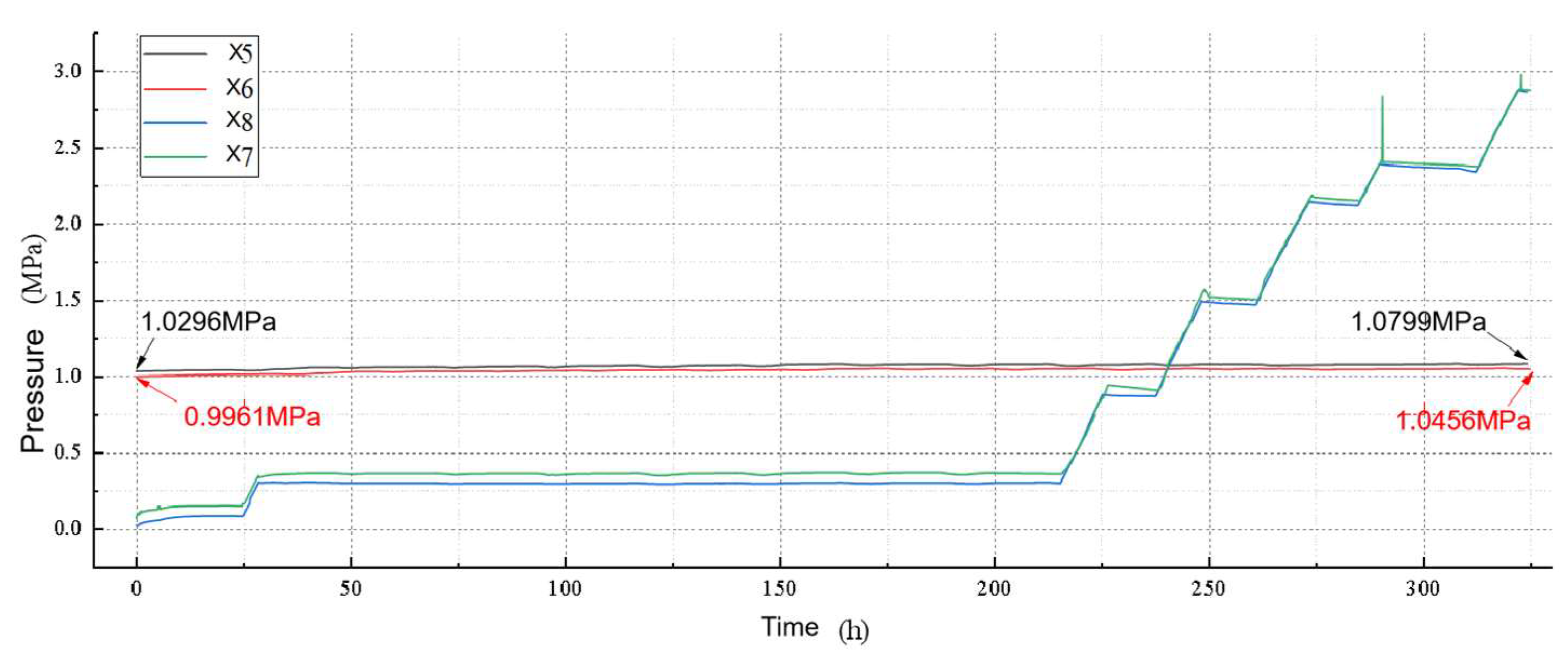
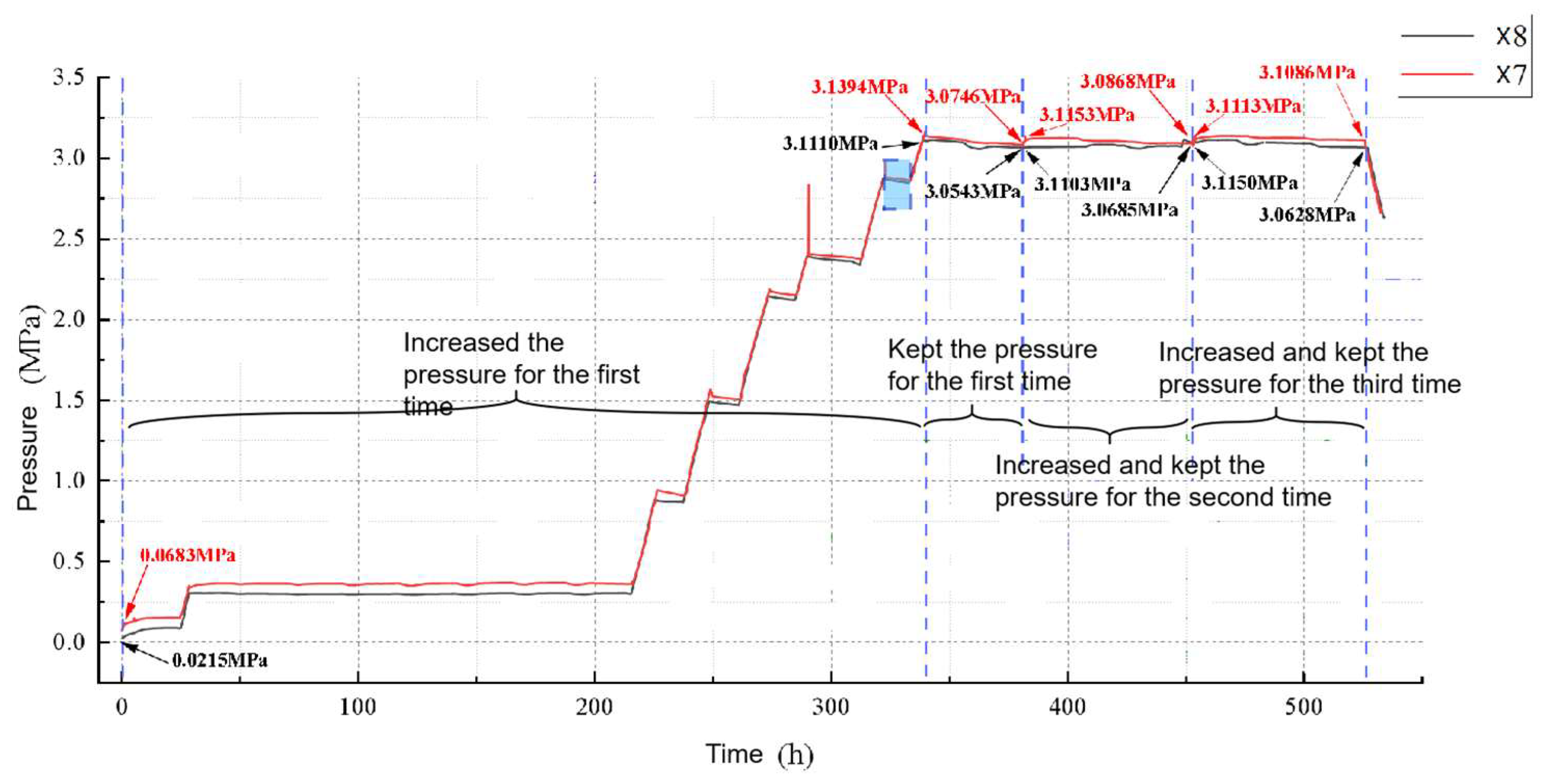
5.4. Water Sealing Test (Tightness)

The water sealing test is a low-cost, convenient, and quick way to initially determine whether there is a connection between old caverns and the tightness of old caverns by monitoring the changes in injected water flow and pressure over time. The tests carried out include well group connection tests and comprehensive tests of the pressure-flow method.

5.4.1. Well Group Connection Test

The on-site well group connection test program is as follows: Discharge the brine in the X5–X6 cavern until the wellhead pressure is about 1.0 MPa and shut down the well. During this period, the X5–X6 well group was injected and the pressure of the X7–X8 well group was continuously monitored. If the wellhead pressure remains unchanged or changes little, the X7–X8 well group can be considered an independent solution cavity. On the contrary, discharge the brine in the X7–X8 well group until the wellhead pressure is about 1.0 MPa and shut down the well. The adjacent X5–X6 well group is subjected to water seal routine water injection, and the wellhead pressure of the X5–X6 well group is continuously monitored.
The connection test of the X7–X8 well group actually lasted about 325 h. Figure 14 shows the pressure changes during the test of X5–X6 and X7–X8 caverns. A water injection operation was carried out for the X7 well, and pressure gauges were installed at the X5, X6, and X8 wellheads for monitoring. During the process, the X5 wellhead pressure increased by 0.0503 MPa, and the X6 wellhead pressure increased by 0.0495 MPa. The wellhead pressure changes of X5 and X6 were not related to the wellhead pressure changes of X7 and X8.
The results of the X5–X6 well group connection test were generally consistent. It was concluded that X5–X6 caverns were not in connection with X7–X8 caverns.

5.4.2. Comprehensive Test of Pressure-Flow Method Integrated Test of Pressure and Flow Method

The comprehensive test of the on-site pressure-flow method involves increasing the salt cavity pressure to the design value, recording the brine injection amount and wellhead pressure changes, holding the pressure for a period of time, and then raising the pressure of the cavern again. The procedure was repeated several times, and then the amount of leakage from the cavity was calculated. If the leakage is getting smaller and lower than the acceptable value, it proves that the cavity has great tightness.
The caverns X7–X8 were subjected to three pressure boosting and pressure holding tests, and each pressure holding duration was not less than 70 h. The monitoring result of X7 and X8 wellhead pressure is shown in Figure 15.
The first pressure boosting and holding stage: due to the limitation of brine transport pipeline and the actual situation of field operation, the duration of holding boosting stage is about 340.5 h, with a total injection volume of 1160.24 m3 of brine (density of 1200 kg/m3); the duration of pressure holding stage is about 92 h, and the pressure drop is 0.0648 MPa in the pressure holding stage of well 307 and 0.0567 MPa in the pressure holding stage of well 308. By calculation, the pressure drop rate during the first pressure holding stage of the 307 well is 0.00137 MPa/h, and that of the 308 well is 0.00151 MPa/h.
The second pressure boosting and holding stage: the pressure boosting stage lasts about 1 h, and 21.25 m3 of fresh water is injected. The pressure holding stage is about 71 h. The pressure drop during the pressure holding stage of well 307 is 0.0285 MPa, and that of well 308 is 0.0418 MPa. During the second pressure holding stage, the pressure drop rate of well 307 is 5.81214 × 10 4 MPa/h and that of well 308 is 3.62243 × 10 4 MPa/h.
The third pressure boosting and holding stage: the pressure boosting stage lasts about 1 h, injecting brine about 19.75 m3. The pressure holding stage is about 72 h, and the pressure drop in this stage of well 307 is 0.0027 MPa, and that of well 306 is 0.0522 MPa. By calculation, the pressure drop rate in the second pressure holding stage of well 307 is 3.58361 × 10 4 MPa/h and that of well 306 is 5.16849 × 10 4 MPa/h.
During the three pressure boosting and holding processes, with the increase in the number of test cycles, the volume of fresh water injected gradually decreases until it approaches 0 when the target pressure value is reached each time. During the three pressure holding processes, as the number of test cycles increases, the average pressure drop rate also decreases until it approaches 0. This means that the leakage volume of caverns decreases gradually over time. It is preliminarily judged that the cavern X7–X8 has good water tightness under target pressure. The comprehensive test results of the pressure-flow method of well group X5–X6 are basically the same.

6. Conclusions

Focusing on the feasibility analysis of the construction of compressed air gas storage by using underground salt cavern resources, this paper analyzes the comprehensive ground conditions, regional geological conditions and formation lithology, salt mine characteristics, salt cavern stability, and tightness, aimed at the regional geology and salt mine characteristics in the Yunying area of Hubei Province. As for the comprehensive ground conditions, it should focus on the construction purpose of the CAES power station and its requirements for the ground environment. The author puts forward a comprehensive evaluation method from the aspects of construction conditions, transportation, water and power supply, power access, and the right to use salt mines. In terms of regional geological conditions, a target salt cavern area with a simple structure, gentle strata, few historical earthquakes, and small magnitude should be selected. In terms of salt mine characteristics, it is proposed to preferentially select independent horizontal butted wells, independent fracturing communicated wells, and horizontal butted wells with two pairs of well groups connected in the same layer. It is required that there are no large buildings on the ground around the salt well and the salt cavern roof is buried more than 500 m deep. In the aspect of salt cavern stability, the ultimate equilibrium failure mode of salt cavern under operating pressure is established by using the limit equilibrium theory, and the calculation method of stability coefficient of target salt cavern is put forward combined with force characteristic. In terms of the tightness of the salt cavern, it is found that salt rock with enough thickness around the salt cavern can be used as the sealing ring to ensure its tightness. The tightness of the target salt cavern can be verified by the field water sealing test.
Based on the above four aspects of analysis and evaluation methods, this paper analyzes the feasibility of transforming the Jiuda salt plants X5–X6 and X7–X8 pair of wells salt caverns into compressed air gas storage in Hubei Yingcheng. The analysis results show that the X5–X6 and X7–X8 pair of wells salt caverns have good conditions for rebuilding compressed air gas storage. The analysis and evaluation method can provide a reference for the reconstruction of compressed air gas storage in other areas.

Author Contributions

Methodology, J.M. and J.W. Investigation, T.X. Writing—original draft, J.M. Writing—review & editing, H.S., W.J. and J.M. Visualization, W.P. Supervision, H.M. Funding acquisition, W.J. All authors have read and agreed to the published version of the manuscript.

Funding

The authors would gratefully like to acknowledge the financial support from the Scientific Research and Technology Development Project of China Energy Engineering Corporation Limited (No. CEEC-KJZX-04).

Data Availability Statement

Not applicable.

Conflicts of Interest

The authors declare no conflict of interest.

References

  1. Kang, Y. Study on the Characteristics of Damage Healing and Reconsolidation of Salt Rock. Ph.D. Thesis, Chongqing University, Chongqing, China, 2021; pp. 45–51. [Google Scholar]
  2. Wan, M.; Ji, W.; Wan, J.; He, Y.; Li, J.; Liu, W.; Jose Jurado, M. Compressed air energy storage in salt caverns in China: Development and outlook. Adv. Geo-Energy Res. 2023, 9, 54–67. [Google Scholar] [CrossRef]
  3. Jiang, Z.; Tang, D.; Li, P.; Li, Y. Research on selection method for the types and sites of underground repository for compressed air storage. South. Energy Constr. 2019, 6, 6–16. [Google Scholar]
  4. Li, Y.; Zou, J. Select and research address of Underground Gas Storage of Yanchang group in Yan’an prefecture, Inn. Mong. Petrochem. Ind. 2021, 47, 98–101. [Google Scholar]
  5. Demirel, N.Ç.; Demirel, T.; Deveci, M.; Vardar, G. Location selection for underground natural gas storage using Choquet integral. J. Nat. Gas Sci. Eng. 2017, 45, 368–379. [Google Scholar] [CrossRef]
  6. Zeng, D.; Hu, Z.; Mi, L. Evaluation standard system and screening platform of different types of underground gas storage sites. Nat. Gas Ind. 2022, 42, 117–124. [Google Scholar]
  7. Zheng, Y.; Wanyan, Q.; Qiu, X.; Kou, Y.; Ran, L.; Lai, X.; Wu, S. New technologies for site selection and evaluation of salt-cavern underground gas storages. Nat. Gas Ind. B 2020, 7, 40–48. [Google Scholar] [CrossRef]
  8. Zhang, B.; Liu, T.; Xi, Z.; Cui, L.; Wu, Y.; Zhou, S. Preliminary evaluation and understanding of underground salt cavern gas storage in the reconstruction of Pingdingshan Salt Mine. Natural Gas Professional Committee of China Petroleum Society. In Proceedings of the 32nd National Natural Gas Academic Annual Conference (2020), Chongqing, China, 13–14 November 2020; pp. 2853–2861. [Google Scholar]
  9. Wanyan, Q.; Ran, L.; Han, B.; Cai, M.; Li, Q. Study on site selection and evaluation of underground gas storage in salt cavern. J. Southwest Pet. Univ. Sci. Technol. Ed. 2015, 37, 57–64. [Google Scholar]
  10. Wu, Z. Zhongxiang Sheet(H-49-11), Yingcheng Sheet(H-49-12) 1/200,000 Regional Geological Survey Report; National Geological Archives: Nanjing, China, 1977. [Google Scholar]
  11. Ma, H.; Liang, X.; Zhao, K.; Shi, X.; Ma, H.; Mo, L.; Yang, C. Geological feasibility analysis of Tai’an salt cavern gas storage in Shandong Province. Hazard Control Tunn. Undergr. Eng. 2022, 4, 19–27. [Google Scholar]
  12. Goryl, L. In 2012–2015 Triennium Work Reports: Working Committee 2: Underground Gas Storage. In Proceedings of the WGC PARIS 2015 World Gas Conference, Paris, France, 1–5 June 2015; International Gas Union: Paris, France, 2018. [Google Scholar]
  13. Li, P.; Li, Y.-P. Pore characteristics and volume capacity evaluation of insoluble sediments for gas storage in multi-interbedded salt formations. Rock Soil Mech. 2022, 43, 76–86. [Google Scholar]
  14. Z341 Series-10; Storage of Hydrocarbons in Underground Formations. Canadian Standards Association: Calgary, AB, Canada, 2011.
  15. Zhang, J.; Zadeh, A.H.; Kim, S. Geomechanical and energy analysis on the small-and medium-scale CAES in salt domes. Energy 2021, 221, 119861. [Google Scholar] [CrossRef]
  16. Fu, X. Stability Analysis of Underground Gas Storage of Salt Cavern in Huangchang, Jianghan Basin. J. Shanxi Datong Univ. Nat. Sci. Ed. 2020, 36, 73–75. [Google Scholar]
  17. Lou, E.; Liu, H.; Li, N. Analysis of Salt Rock Creep Mechanical Properties. In Proceedings of the Chinese Materials Conference 2021, Sanya, China, 13–15 November 2021; pp. 157–164. [Google Scholar]
  18. Liu, X. Research of Creep Properties and Constitutive Model for Salt Rock Subjected to Low-Frequency Cyclic Loading. Master’s Thesis, Xi’an University of Architecture and Technology, Xi’an, China, 2022. [Google Scholar]
  19. Kang, Y.; Chen, J.; Jiang, D.; Liu, W.; Fan, J.; Wu, F.; Jiang, C. Damage self-healing property of salt rock after brine immersion under different temperatures. Rock Soil Mech. 2019, 40, 601–609. [Google Scholar]
  20. Kang, Y.; Chen, J.; Jiang, D.; Liu, W.; Fan, J. Summary on the damage self-healing property of rock salt. Rock Soil Mech. 2020, 40, 55–69. [Google Scholar]
  21. Tang, Z.; Jiang, D.; Chen, J.; Fan, J.; Liu, W. Comprehensive Evaluation of the Stability of Two Well Salt Cavern Storage with Small Well Spacing. Chin. J. Undergr. Space Eng. 2021, 17, 1997–2006. [Google Scholar]
  22. Zhang, G.; Wang, Z.; Liu, Y.; Lou, N.; Dong, J. Research on stability of the key roof above horizontal salt cavern for compressed air energy storage. Rock Soil Mech. 2021, 42, 800–812. [Google Scholar]
  23. Wan, J.; Meng, T.; Li, J.; Liu, W. Energy storage salt cavern construction and evaluation technology. Adv. Geo-Energy Res. 2023, 9, 141–145. [Google Scholar] [CrossRef]
  24. Liu, Z.-Z.; Ping, C.; Hang, L.; Meng, J.-J.; Wang, Y.-X. Three-dimensional upper bound limit analysis of underground cavities using nonlinear Baker failure criterion. Trans. Nonferrous Met. Soc. China 2020, 30, 1916–1927. [Google Scholar] [CrossRef]
Figure 1. Aerial view of 300 MW compressed air energy storage power station in Yingcheng, Hubei.
Energies 16 07171 g001
Figure 2. Bedrock geology map of Yunying salt mine area [10].
Energies 16 07171 g002
Figure 3. Horizontal butted well.
Energies 16 07171 g003
Figure 4. Fracturing communicated well.
Energies 16 07171 g004
Figure 5. Plane distribution of four old wells.
Energies 16 07171 g005
Figure 6. Coring photos of some saline formations. (a) Buried depth of 423~427 m. (b) Buried depth of 427~431 m. (c) Buried depth of 431~435 m.
Energies 16 07171 g006
Figure 7. Three-dimensional picture of X5–X6 cavity.
Energies 16 07171 g007
Figure 8. Three-dimensional picture of X7–X8 cavity.
Energies 16 07171 g008
Figure 9. Three-dimensional display of X5–X6 and X7–X8 pairs of well cavities.
Energies 16 07171 g009
Figure 10. Geological profile of A’-A bedrock in Yunying salt mine area [10].
Energies 16 07171 g010
Figure 11. Structure diagram of top plate in the study area.
Energies 16 07171 g011
Figure 12. Structure diagram of bottom plate in the study area.
Energies 16 07171 g012
Figure 13. Calculation model of salt cavern stability.
Energies 16 07171 g013
Figure 14. Pressure change curve of well group connection test.
Energies 16 07171 g014
Figure 15. X7 and X8 wellhead pressure monitoring curve with comprehensive tests of the pressure-flow method.
Energies 16 07171 g015
Table 1. The cost and performance prediction levels of different types of energy storage technologies.
Energy Storage TechnologyCost (RMB/kW)Overall
Efficiency (%)
Life Cycle (Years)AdvantageDisadvantage
Pumped storage power station70007040~50Mature large-scale technologyDifficult site selection, and long construction period
Compressed air energy storage70007030~50Large-scale energy storageDifficult site selection and few mature applications
Electrochemical energy storage2000905High efficiency, fast response, used for FM energy storageShort storage time, high cost for long time energy storage
Hydrogen storage13,00040≥10Large-scale energy storageHigh cost and low efficiency
Table 2. List of strata of salt mines in the Yunying area [10].
ErathemSystemStratigraphyThickness (m)Lithological Features
FormationCode
CenozoicQuaternary System Q11–153The Pleistocene is yellow, red, and off-white clay, sand, gravel, and clay-bearing gravel; the Holocene is light yellow, dark brown, and gray sandy clay of recent times. It is in unconformable contact with the underlying strata.
Tertiary SystemDudaoshi N2d0–50Grayish to yellowish mudstone and claystone with yellowish brown conglomerate at the bottom. Only seen in individual drill holes. This mine was not drilled.
Neogene SystemWenfengta Ew3–480The lower part is gray-green and ochre calcareous mudstone and calcareous siltstone with fibrous paste and fossilized mesomorphs; the upper part is light green, gray-white, and ochre marl with siltstone. It is in integrated contact with the underlying strata.
GaoyanEg394–1598It is mainly a set of gray and ochre-colored mudstone, siltstone, and salt rocks such as muddy gypsum, hard gypsum, and calcium mannite. It is divided into five sections, including the lower hard gypsum section Eg1, the lower calcium mannite section Eg2, the saltstone section Eg3, the upper calcium mannite section Eg4, and the upper hard gypsum section Eg5, according to the mineral assemblage containing saltstone, calcium mannite, hard gypsum, and gypsum. It is in integrated contact with the underlying strata.
BaishakouEb694–920The lower part is red sandstone and conglomerate-bearing sandstone, and the upper part is red siltstone and muddy siltstone with a thin layer of fibrous paste. It is in integrated contact with the underlying strata.
YutaishanEy727Red sandstone, muddy siltstone, sandy shale, and conglomerate with rhyolite development and integrated contact with underlying strata.
Table 3. Mining layers of Yunying salt mine.
Mining LayersSalt GroupBuried Depth (m)
KK2CX76ZK1011
K1K2408.71 m (Roof)304.70 m (Roof)206.59 m (Roof)
427.80 m (Floor)321.01 m (Floor)219.65 m (Floor)
K2K4/K5483.80 m (Roof)372.56 m (Roof)266.71 m (Roof)
534.69 m (Floor)419.50 m (Floor)307.17 m (Floor)
K3K8633.90 m (Roof)Not drilled395.67 m (Roof)
648.16 m (Floor)Not drilled399.36 m (Floor)
K4K10743.37 m (Roof)Not drilledNot drilled
751.50 m (Floor)Not drilledNot drilled
Table 4. Survey of X5–X6 and X7–X8 salt well leaching in the water mining area of Jiuda salt plant (as of the end of 2021).
Salt WellMining LayersBuild Well TimeLife in Service (Years)Roof Depth (m)Accumulated by Salt (×104 t)Volume of the Cavity (×104 m3)Mode of Wells ConnectedStatus Quo
X5K5198929599.3518455.2fracturing communicatedClosed
X6K5
X7K5199028604.2517652.8fracturing communicatedClosed
X8K5
Table 5. Sonar measurement results.
Cavity PositionVolume/104 m3Buried Depth/mMaximum Radius/mMaximum Span/mCentrifugal RateLimit Segregation Rate
X53.0545~58055590.23460.3088
X69.3508~53437750.45760.4670
X74.6534~564901080.09850.1374
X85.2521~537921050.24870.2487
Table 6. Statistical table of comprehensive interpretation of three-position seismic measurement in salt caverns.
Well NumberTop Boundary Elevation/mFloor Elevation of Salt Well/mTop Boundary Elevation of Salt Cavity/mFloor Elevation of Salt Cavity/mCavity Thickness Range/mCavity Estimated Volume/m3
X7−503−529−515~−469−543~−4710~36783,699
X8−488−524.5
X5−518.5−552−527~−470−552~−4910~44795,188
X6−490−528.5
Table 7. Stratigraphic data table of each stratum.
System
(Formation)
MemberSalt GroupThickness
(m)
Weight
(kN/m3)
Cohesive Force (kpa)Angle of Internal Friction (°)The Lateral Pressure Coefficient
Quaternary System 9020
Neogene System
(Wenfengta Formation)
18021
Neogene System (Gaoyan Formation)Gypsum intervals
(Eg5)
9023
Calcium Mirabilite intervals
(Eg4)
3022
Salt intervals
(Eg3)
K125225130411
K225215130411
K33521436039.91
K430215130411
K5321436039.91
Disclaimer/Publisher’s Note: The statements, opinions and data contained in all publications are solely those of the individual author(s) and contributor(s) and not of MDPI and/or the editor(s). MDPI and/or the editor(s) disclaim responsibility for any injury to people or property resulting from any ideas, methods, instructions or products referred to in the content.

