Article

Centralized Protection of Networked Microgrids with Multi-Technology DERs

by
Adeyemi Charles Adewole
1,
Athula D. Rajapakse
1,*,
Dean Ouellette
2 and
Paul Forsyth
2
1
Department of Electrical and Computer Engineering, University of Manitoba, Winnipeg, MB R3T 5V6, Canada
2
RTDS Technologies Inc., Winnipeg, MB R3T 2E1, Canada
*
Author to whom correspondence should be addressed.
Energies 2023, 16(20), 7080; https://doi.org/10.3390/en16207080
Submission received: 2 August 2023 / Revised: 5 September 2023 / Accepted: 9 October 2023 / Published: 13 October 2023
(This article belongs to the Topic Control and Optimization of Networked Microgrids)

Abstract

:
The structure and connections in networked microgrids consisting of two or more interconnected microgrids is influenced by the dynamic behaviors of power markets, the demand and supply interactions between market participants, and the possibility of operating in the grid-connected or islanded modes. Protection zones in the above-mentioned scenarios are dynamic and should not be determined a priori. Also, fault currents will vary depending on the operating modes, online or offline status of Distributed Energy Resources (DERs), variation of solar irradiation or wind speed, etc. This paper proposes a Centralized Intelligent Station-Level Protection (CISP) approach for the protection of various electric power equipment technologies in networked (interconnected) microgrids using adaptive protective relaying algorithms and a network theory-based zone selection algorithm. The proposed CISP approach utilizes wide area IEC 61869-9 Sampled Values (SVs) measurements and IEC 61850 Generic Object-Oriented Substation Events (GOOSE) messages, intelligently determines the protection zones, and automatically selects the protection algorithms to use in each of the protection zones based on the prevailing system topology and operating conditions. The effectiveness of the proposed CISP approach is demonstrated through real-time simulations using the RTDS®. The results obtained were promising for the various system configurations, operating conditions, and fault conditions considered.

1. Introduction

Several methods have been proposed in the literature for microgrid protection. Most of these methods centered on the use of traditional current-based protection, voltage-based protection, and frequency-based protection. Non-traditional techniques derived from the above-mentioned methods have been the focus of recent research works.

1.1. Background

In [1,2,3], traditional overcurrent (OC) and directional OC protection functions were investigated in the protection of microgrids. OC-based protection such as superimposed positive and negative sequence-based OC protection [4] and harmonic directional OC relay [5] have also been researched with promising results. Microgrid protection using current differential protection principles was presented in [6,7,8,9]. Similarly, ref. [10] presented a method based on the cumulative sum of the differential negative-sequence impedance angle. In [11], a hybrid method based on the combination of an impedance differential technique and an inverse-time low impedance technique was proposed.
Other interesting methods in the literature include the comparison of dq synchronous frame voltages of Distributed Energy Resources (DERs) [12], Total Harmonic Distortion calculations [13], under/over frequency relays [14], mathematical morphology-based method using current travelling wave [15], directional phase and negative sequence overcurrent elements, undervoltage elements, current and voltage total harmonic distortion elements [16], methods based on differential frequency [17], and spectral energy differential method [18].
However, overcurrent protection may have delayed protection operation time due to low fault currents, loss of sensitivity in the islanded mode, difficulty in maintaining selectivity in loop feeders, and coordination problems. Also, current differential relays require protection systems and end-to-end high-bandwidth communication equipment at both ends of each line segment. Furthermore, protection techniques based on traditional negative- and zero-sequence currents requires negative- and zero-sequence currents to function. Inverter-based DERs have been known to have insignificant negative- and zero-sequence currents during faults. In addition, voltage and frequency-based protection lack selectivity, are vulnerable to switching conditions, and are difficult to coordinate since voltage drop and frequency may be the same across a system.
The coordination of individual protection devices in traditional power systems is usually based on current, time, or current-time grading. This is not often possible in inverter-based microgrids because of the intermittent nature of the DERs, low inertia, changes in short circuit fault current levels, and low short-circuit currents especially when operating in the islanded mode. This makes protection coordination of overcurrent protection relays in microgrids particularly difficult. In [19], a mathematical approach for protection coordination using a genetic algorithm was applied in the minimization of protection operating time. In [20], the coordination of directional OC protection relays was proposed by placing a fault current limiter at the point of common coupling (PCC). Current-time grading or coordination of traditional directional/non-directional overcurrent protection in a networked microgrid is particularly difficult when there is a high penetration level of inverter-based systems with low inertia and fault current contributions [21,22].
The use of optimization algorithms in solving the protection coordination problem as proposed in some literature cannot be practically implemented in the available protection relays in real-time and will also result in delayed fault clearing. Any effective adaptive protection solution applicable to complex networked microgrids invariably involves communication. Communication-assisted protection principles provide faster fault clearance, and improve protection efficiency, security, and dependability.

1.2. Related Work

The implementation of centralized protection can provide engineering, cost, and reliability advantages when compared to traditional protection by local distributed protection devices and the individual communication between these distributed devices, especially under dynamically changing topology and operating modes. In a centralized scheme, the communication architecture required is simpler, and providing redundancy and maintenance of protective devices is more efficient and cost-effective. Also, the communication infrastructure already in place for microgrid control communication can be used for microgrid protection.
Recently, centralized protection approaches were proposed in [23,24,25,26] for traditional systems, and in [27,28,29,30,31,32,33] for DER-integrated systems. However, most of the methods made use of architectures with local distributed protective relays communicating with a centralized decision-making platform. Such approaches do not completely solve the protection issues associated with DER integration and microgrids. For example, a change in system topology or generated power could cause the local protective relays to misoperate and communicate wrong decisions to the centralized platform.
Also, the decision-making process at the centralized protection platform could become impossible if it receives conflicting decisions from multiple local protective relays. Furthermore, some of the existing methods in the literature were proposed for the protection of a specific power apparatus in the substation, and not for the simultaneous protection of multiple electric power equipment. In addition, these methods did not consider the dynamic nature of the topology of interconnected power systems and made use of fixed pre-determined protection zone models. A summary of some of the relevant literature is presented in Table 1.
In view of the foregoing, a Centralized Intelligent Station-Level Protection (CISP) approach based on dynamic network theory and wide area measurements is proposed in this paper for interconnected power systems such as networked microgrids. This paper extends the protective relaying algorithms proposed by the authors in [34] to the protection of interconnected or networked microgrids.
The unique features of the proposed CISP approach and the contributions of this paper are as follows: Firstly, the proposed CISP does not require the use of multiple local relays. Rather it replaces them with a single, reliable, and cost-effective station-level centralized protection platform. Secondly, the protection module implemented in the proposed CISP is adaptive to the prevailing networked microgrid configuration using an adaptive network-theory based dynamic zone selection approach and protective relaying algorithms suitable for dynamic system topologies, high DER penetration levels, and systems with multi-technology DERs. The advantages of using adaptive protection algorithms include the following: (i) the ability of the protection algorithms to adapt or adjust to changes in the microgrid topology, changes in microgrid loading, changes in the number of DERs in service, and changes in DER penetration levels, (ii) the ability to function in any of the microgrid operating modes (i.e., grid-connected or islanding modes), and (iii) the ability to adapt to changing fault current levels. Thirdly, this paper proposes a centralized protection concept for networked microgrids, thereby reducing the use of multiple distributed protective relays. Fourthly, the proposed centralized protection system was implemented and tested using a real-time ‘proof-of-concept’ RTDS® testbed. Lastly, this paper applied and investigated the merits of next-level power automation communication protocols such as the IEC 61850-8-1 Generic Object–Oriented Substation Events (GOOSE) [35] and the IEC 61869-9 Sampled Values (SVs) [36] in networked microgrids.
The remainder of this paper is structured as follows. Section 2 discusses the various CPC architectures possible for traditional and networked microgrid systems, while Section 3 presents the proposed CISP platform for microgrid protection. Section 4 describes the practical proof-of-concept real-time simulation RTDS® testbed used in testing and validating the proposed CISP platform. Section 5 discusses the results obtained from several use cases, while Section 6 summarizes the contributions of this paper.

2. Centralized Protection and Control

Advancements in communication and measurement technologies have accelerated the potential use of centralized protection in power systems. The requirements for centralized protection schemes and the available communication or measurement technology vary between utilities. Thus, the architecture used may also vary. Some important elements required in the implementation of a reliable centralized protection scheme include the communication media, the communication protocol, and the topology of the network, amongst others. The communication media can be Power Line Carrier (PLC), microwave, radio, leased lines, satellite, or fiber-optic links. Some issues that need to be considered in the selection of utility communication architectures are communication bandwidth, latency, scalability, flexibility, redundancy, and cyber security.
The following subsections summarize the architectures discussed in [37] and the architecture proposed in this paper for Centralized Protection and Controls (CPCs) in networked microgrids.

2.1. CPC Architecture for Conventional Systems

Five possible CPC architectures were presented in the IEEE WG K15 report [37]. Figure 1 shows the architecture ranked in the report as the most used. In this architecture (denoted as architecture 5a in [37]), the instrument transformers are interfaced to Intelligent Merging Units (IMUs) at the process level, while the IMUs are interfaced to the CPCs over the process bus Ethernet Local Area Network (LAN).
Other CPC architectures (CPC architectures 1, 2, 4) in the report [37]) had process level devices interfaced to the Intelligent Electronic Devices (IEDs) in the bay level using traditional hardwiring or Ethernet-based SVs from IMUs. The IEDS communicate information to station level CPC using IEC 61850 GOOSE [35], IEC 61869-9 SVs [36], or IEEE C37.118 synchrophasors [38]. The primary Protection and Control (P&C) functions are performed by the IEDs, and the CPC serves as backup protection. In architectures 3, 5, 5a, the individual bay level IEDs are replaced by CPCs. The protection and control functions are performed by a primary CPC (CPC-A) and a redundant CPC (CPC-B), respectively.

2.2. Proposed CPC Architecture for Networked Microgrids

Figure 2 shows the architecture proposed in this paper for networked microgrids. In this architecture, the process level instrument transformers and IMUs at networked microgrids are interfaced directly to a station-level CPC (CISP) over a communication network, thereby eliminating the use of protection and control devices (multiple bay devices) at the bay level. In the proposed architecture, the wide area protection and control functions are performed at a central location for all the networked microgrids, and do not require distributed IEDs or individual CPCs in the microgrids. As a result of using centralized processing and protection principles, the protection miscoordination of the main and backup protection device is minimized. In practical systems, the CPC could be located at any of the microgrids or at the nearest utility substation control house (if the microgrid is owned by the utility) and should be capable of receiving data communicated to it from all member microgrids.
Thus, a fast and secure communication network between microgrids or between microgrids and a utility substation control house is required. This communication can easily be implemented using the IEC 61850 standard. The IEC 61850 specifies the use of redundancy protocols such as the Parallel Redundancy Protocol (PRP) and the High-Availability Seamless Redundancy (HSR) protocol [39]. The PRP and HSR redundancy protocols provide seamless failover in the case of a single point of failure in communication networks. In order to deal with severe multiple communication disruptions, uncoordinated local back-up overcurrent and breaker-failure protection functions can be provided on the merging units, as available in some commercially available merging units [40].
The IEC 61850 standard [35] is a suite of communication standards for power utility automation that specifies the data modelling approach, structure, communication models and service, and Substation Configuration Language (SCL) used in defining the various functions in power systems. Edition 2 of the IEC 61850 covers DER-related applications, Routable-Sampled Values (R-SV), Routable-GOOSE (R-GOOSE), etc. [35]. R-SV and R-GOOSE could be used in the proposed architecture in Figure 2 for publishing the measurements and control signals to and from the microgrids to the CISP platform in the control house. Note that individual microgrids could have station-level monitoring and metering functionalities. However, the P&C decisions would be performed only at the centralized protection level.

3. Design of the Proposed Centralized Protection Platform

The proposed CISP platform requires system-wide measurements from widely dispersed sensors, IMUs, and field devices in order to intelligently detect and isolate the faulted segment of the networked microgrids. This can easily be achieved by using the peer-to-peer communication framework (Figure 2) proposed in this paper for centralized protection.
Three modules are implemented in the CISP platform. These are the following: (i) the Zone Selection (ZS-) Module, (ii) the Protection (P-) Module, and (iii) the Actuation (A-) Module. Figure 3 shows the flowchart for the proposed CISP platform. The ZS- Module functions as a system-wide adaptive topology processor and zone determination algorithm. It receives and processes the status of the Fault Interruption Devices (FIDs) and the status of the DERs in the microgrids and applies network theory in the creation of a network graph corresponding to the prevailing topology of the networked microgrids. The network graphs formed are used to automatically create the protection zones in the microgrid. The type of zones created can be subgraphs, paths, or end-hub zones. Subgraphs are essentially bus protection zones Z B , while the paths between two or more subgraphs are designated as protection zones Z F . The paths between the trivial (end) nodes and the hubs are designated as protection zones Z E H .
Once the prevailing system topology and the protection zones ( Z B , Z F , or Z E H  zones) have been identified by the ZS- Module, the next stage after the ZS- Module is by the P-Module. The P-Module assigns protection algorithms to the identified protection zones. The type of protection algorithm that will be assigned will be detemined by the protection zone type. The A-Module receives the trip signals from the P-Module and the relevant FID for such zone will be tripped in order to isolate the faulty segment of the interconnected system. These CISP modules are further described in the proceeding subsections.

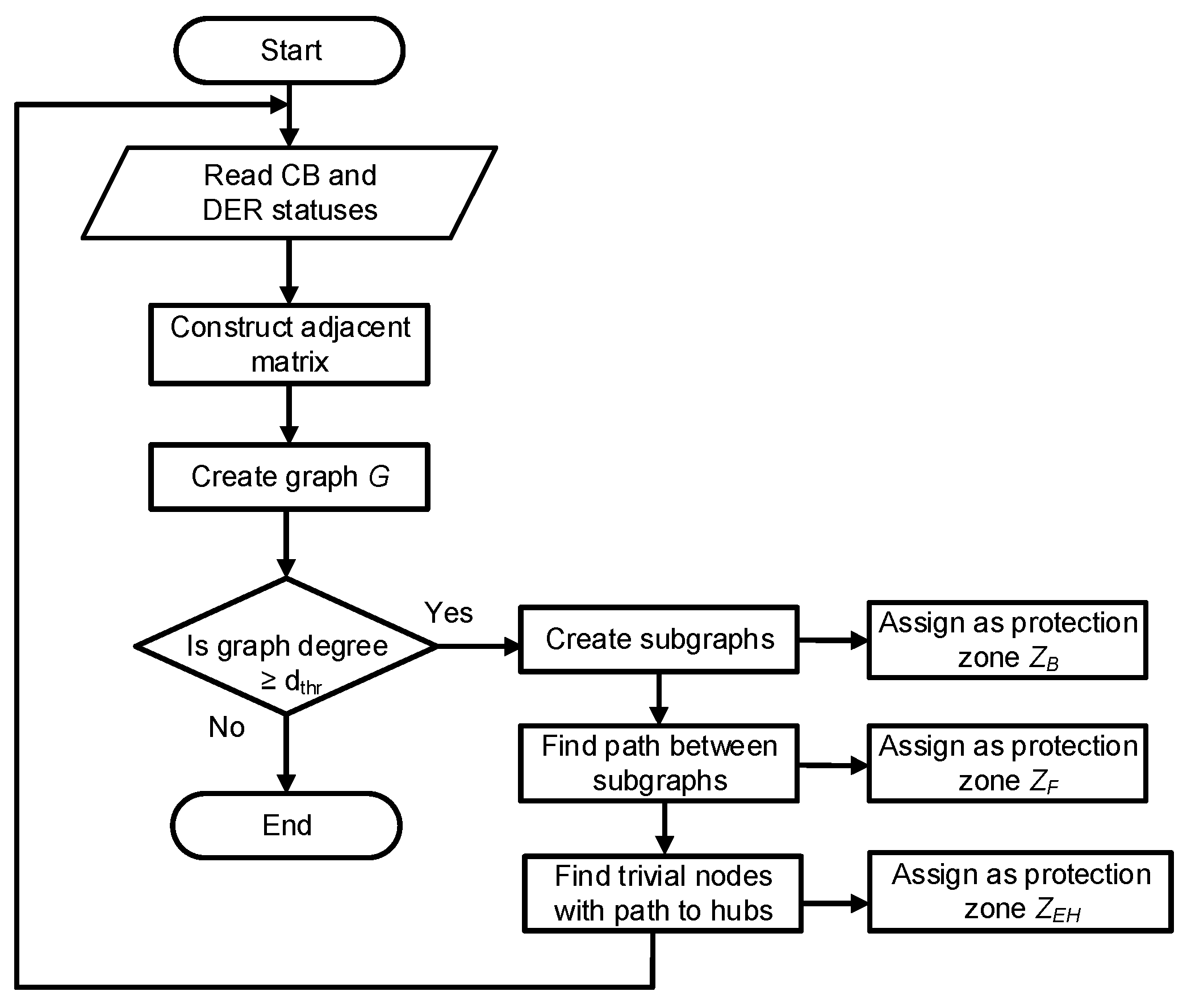
3.1. Zone Selection Module

Interconnected power systems and networked microgrids have dynamic topologies that are influenced by power markets and the dynamic connection/disconnection of nodes (loads) and DERs. Thus, the protection zones in such systems will frequently change and should not be determined a priori. Protection systems must be capable of detecting all fault types, interrupting fault currents, and locating and isolating the faulted section before any damage. It is obvious that an intelligent and adaptive zone selection method is essential and crucial to the performance of protection systems used in interconnected power systems or microgrids with dynamic system operating conditions.
The Zone Selection (ZS-) Module proposed in this paper is comprised of a system-wide topology processor and a zone determination algorithm, respectively. The ZS- Module receives, processes, and tracks the changes in the status of the Fault Interruption Devices (FIDs) and the DERs in the microgrids, and applies network theory in the creation of a network graph corresponding to the prevailing topology of the networked microgrids.
  • Graph Theory: Graph theory is a major branch of combinatorial mathematics and has been extensively applied in various fields [41]. Networked microgrids with n nodes comprised of two or more interconnected microgrids can be modelled by a graph G V , E  using an n × n  adjacency matrix A . Vertices V = v 0 , v 1 , , v n  is a non-empty finite set of elements and the edges.
    E = ( v 0 , v 1 ) , , ( v i , v j ) , , ( v m , v n )    is a finite set of unordered elements. An edge e i j  is a pair of vertices ( v i , v j ) , and v i  and v j  are referred to as adjacent or neighboring vertices. A = a i j  and the element a i j = 1  if the nodes i and j are linked by an edge, while a i j = 0  if otherwise.
  • Proposed Zone Selection Method: Table 2 presents the descriptions used in this paper to show the relationship between power system components and graph components. Some graph theory terminologies given in [41] are adopted in the proposed Zone Selection Module as given below:
Definition 1.
A subgraph  H V ( P ) , E ( P )  is the graph induced by a subset of vertices V with degree  d v > d t h r  in each of the microgrids.
V P = x 0 , x 1 , , x r  
E P = ( x 0 , x 1 ) , ( x 1 , x 2 ) , , ( x r 1 , x r )  
Such that V ( P ) V , E ( P ) E , H G , and x 0 , x r  are end vertices.
The subgraphs are obtained for vertices with degree d v > d t h r , where d t h r  is a user-defined threshold for determining how subgraphs are created. The choice of the d t h r  threshold is system-specific and depends on the power system topology. Typically, this will be ≥2 since a typical distribution busbar microgrid will have at least one incoming feeder and one or more outgoing feeder(s). The number of feeders connected to such a bus should be set as the d t h r  threshold.
Definition 2.
The degree of a vertex is the summation of the number of edges connected to that vertex.
Definition 3.
Hubs are vertices with a high degree value and represents the central vertex connecting all the other vertices.
Definition 4.
The shortest path d i j  (distance) between vertices i and j is the path with the fewest number of links and is found using the Depth First Search (DFS) algorithm.
Definition 5.
The diameter d m a x  is the maximum shortest path in the network. The diameter between the end nodes and the subgraph with the highest centrality is found.
A flowchart of the zone selection process is shown in Figure 4. The proposed zone selection algorithm was designed to dynamically determine the structure or topology of the networked systems at any given time by creating a network graph from the adjacency matrix constructed from the system-wide information from the nodes and DERs in the system. Subgraphs are obtained from the network graphs and are assigned as bus protection zone- Z B , while the path between subgraphs are assigned as line protection zone- Z F . The paths between the trivial (end) nodes and the hubs are designated as feeder protection zone- Z E H .

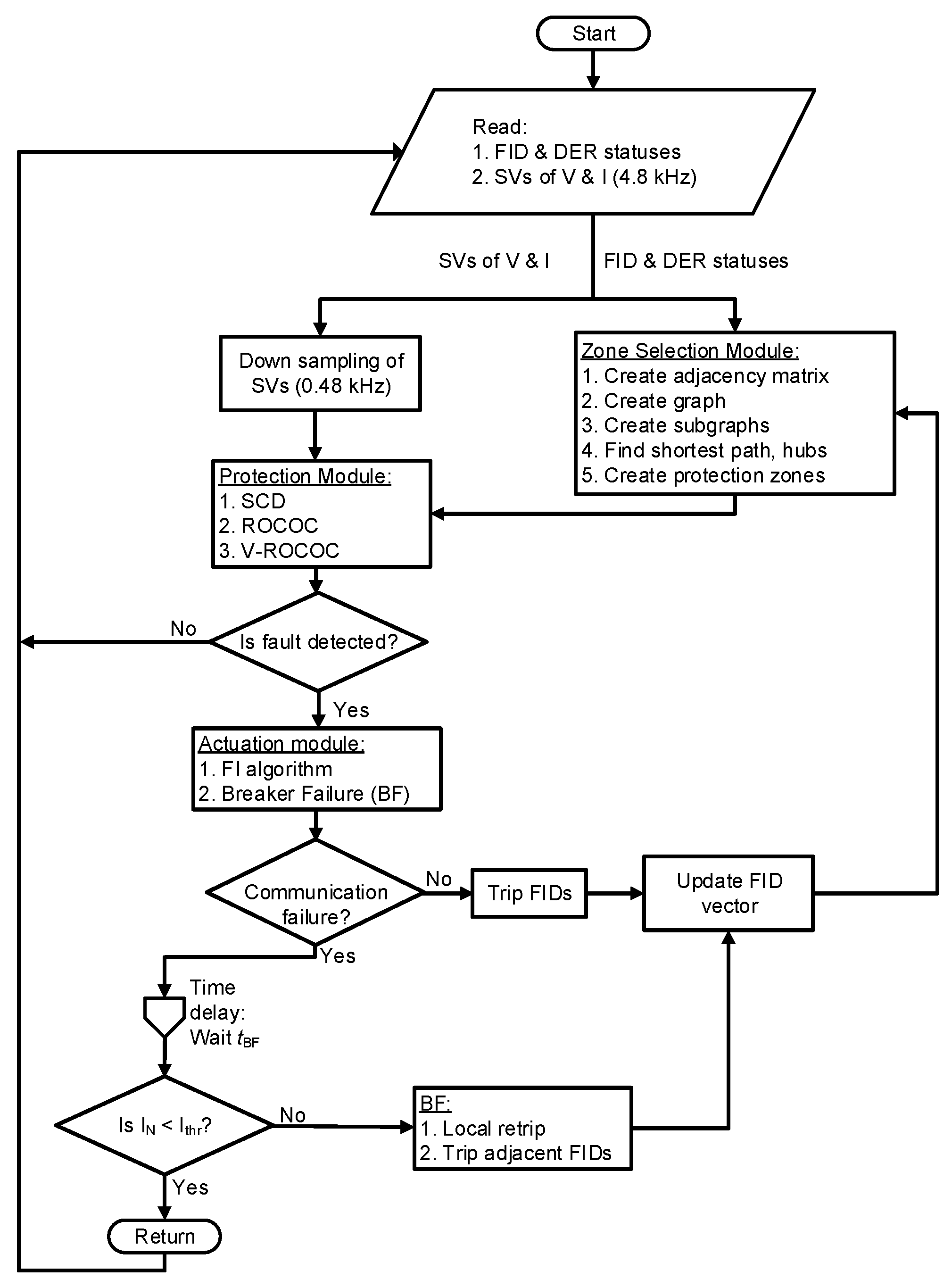
3.2. Protection Module

The CISP platform implements multiple instances of the protection algorithms proposed by the authors in [34] in protecting the various equipment technologies located in the protection zones obtained using the Zone Selection Module described in Section 3.1. The type of protection function implemented at a protection zone depends on the electrical equipment in the protection zone, with the assumption that there are dedicated unit protections for DERs, DER step-up transformers, and interconnection power transformers in order to satisfy the DER fault ride-through requirements and to prevent transformer inrush during energization. Also, the availability of IEC 61869-9/IEC 61850-9-2 [36] compliant IMUs and high-speed communication networks using R-SV and R-GOOSE protocols with worst case communication delay less than 20 ms is assumed.
The protection algorithms proposed by the authors are integrated into a centralized protection platform. The protection algorithm includes directional Supervised Current Differential (SCD), Rate-of-Change of Current (ROCOC), and Voltage-controlled ROCOC (V-ROCOC) algorithms, respectively.
  • Incremental Transient-Energy-Based (ITE) Algorithm: The directional algorithm based on Incremental Transient Energy ( I T E 32 P G ) is obtained from superimposed current and voltage quantities. This is calculated as the integral of the product of the incremental modal (interphase) voltage and current quantities. The interphase I T E 32 P G  (for phases AB) is given as [34]:
    I T E 32 P G t = 0 T v A B t · i A B   d t
    i A B = i A f a u l t i B f a u l t i A p r e i B p r e
    v A B = v A f a u l t v B f a u l t v A p r e v B p r e
    where v A B  and i A B  are incremental voltage and current quantities for phases AB and v A f a u l t , i A f a u l t , v A p r e , i A p r e  are the voltage and current fault and prefault quantities, respectively. Similar derivations can be performed for the modal phase CA.
    One major advantage of the proposed ITE-based directional algorithm is its suitability for inverter-based microgrids with insignificant zero- and negative-sequence fault currents. Traditional zero- and negative-sequence directional algorithms may fail or even be deactivated during faults with insignificant zero- and negative-sequence fault currents.
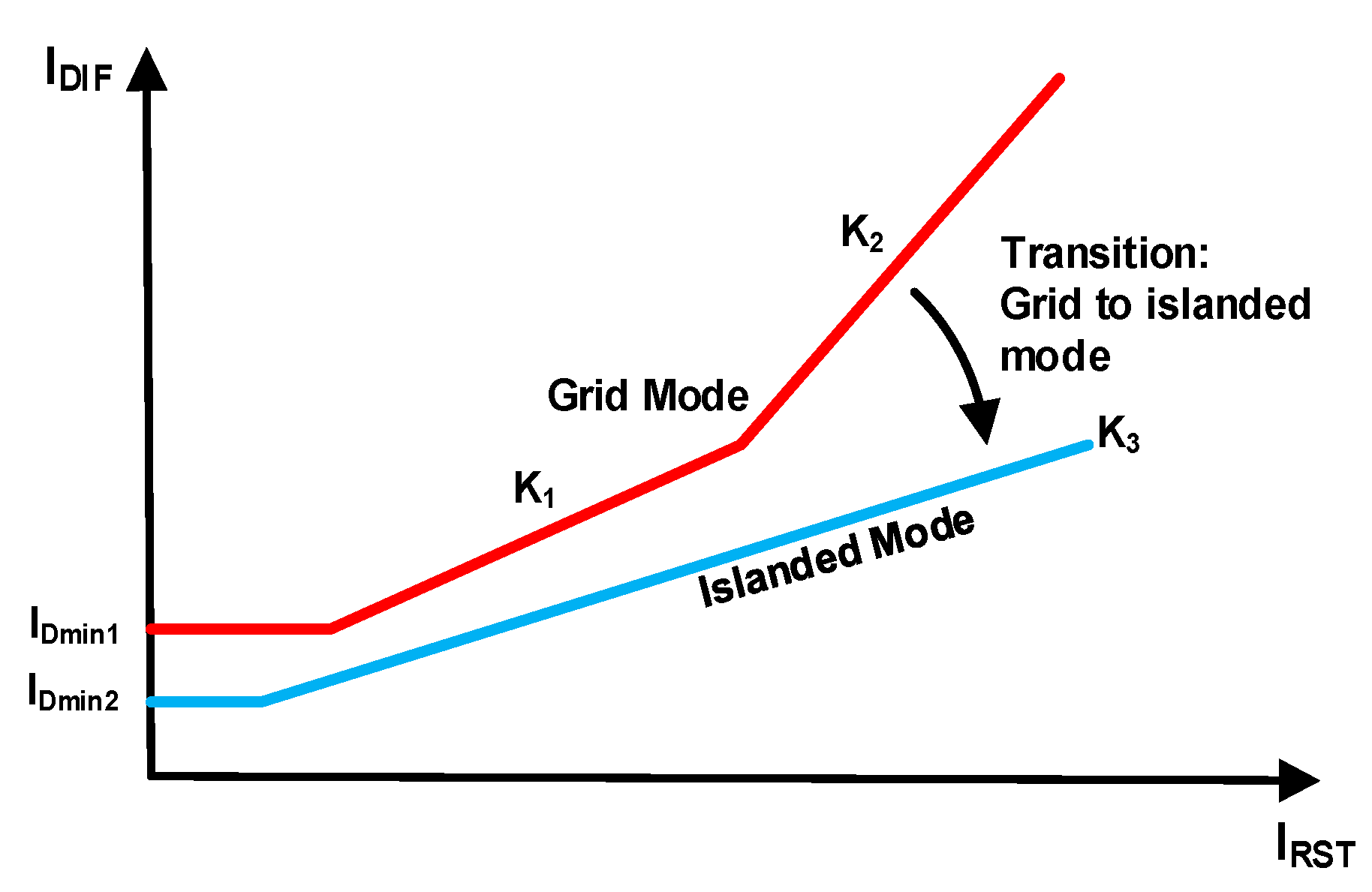
  • Supervised Current Differential (SCD) Algorithm: The differential current I D I F is calculated as the summation of all the line currents at the protected zone on a per phase basis, while the restraining current I R S T  is calculated using the maximum current from any of the feeders in the protected zone.
    I D I F , P h = k = 1 N i k , P h ( t )
    I R S T , P h = k r e s × m a x I k , P h ( t )
    where i k  is the current at the kth feeder, I k  is the magnitude of the current at the kth feeder, N  is the number of line feeders connected to the protected zone, P h  denotes phases A, B, C, and k r e s  is the restraining current multiplying factor (typically 0.5 or unity).
The SCD algorithm proposed in this paper has a multi-slope percentage differential characteristic as shown in Figure 5. The dual slope percentage differential characteristic portion can be written as [34]:
I D I F , P h f 1 ( I R S T , P h )   w h e n   I R S T < I R 2 , P h f 2 ( I R S T , P h )   w h e n   I R S T I R 2 , P h
where:
f 1 I R S T , P h   = I D m i n , P h + K 1 I R S T , P h   f 2 I R S T , P h   = I D m i n , P h + K 1 K 2 I R 2 , P h + K 2 I R S T , P h  
I D m i n , P h  is the minimum threshold for the differential current per phase and is adaptive to the system operating mode (grid-connected or islanded). I R 2 , P h  is the restraining current per phase at the slope changing point. I D m i n 1  and I D m i n 2  are the minimum differential current thresholds for the grid-connected and islanded modes, respectively.
K 1  and K 2  are the first and second slopes for light and heavy loading conditions, respectively. K 1  is typically set to 0.2–0.3, while K 2  is set at 0.5 and is required for high fault current conditions. K 3 is the slope for the islanded mode of operation. K 1  considers only the steady-state sources of differential currents (CT errors) and is set to 0.3, while K 2  is set to accommodate transient differential currents due to CT saturation. K 2  is set to 0.5. K 3  is used in the islanded mode and is set to 0.2.
The key advantages of the proposed algorithms can be summarized as follows:
(a)
adaptive multi-slope percentage differential characteristics compared to traditional percentage dual-slope differential characteristic techniques,
(b)
the differential characteristic of the proposed SCD algorithm dynamically changes from a dual slope characteristic (when in the grid-connected mode) to a single slope characteristic (when in the islanded mode), and
(c)
the ITE-based directional supervision enhances the sensitivity, selectivity, and security of the SCD algorithm.
3.
Rate-of-Change of Current Algorithm: The ROCOC at the jth line lateral is given as [34]:
d i j d t = i n j i n 1 j T s
where i n j , i n 1 j  are the sampled currents at the present and previous sampling instants at the jth line lateral and T s  is the sampling interval (2 ms).
Table 3 summarizes the type of protection algorithms per protection zone. This is based on the type of protection zone identified by the ZS-module. For example, if a ZB zone is identified, the SCDITE,bus protection algorithm is automatically assigned to that protection zone.
The above-mentioned algorithms are based on the premise that during faults in inverter-dominated microgrids, the fault currents are limited by the inverter control actions. Unlike in traditional distribution systems where fault current magnitudes are used for protection decisions, the differential currents, incremental (superimposed) quantities, and the rate of change of current algorithms make use of only the transients generated during fault, and do not depend on sustained fault current magnitudes. Also, the proposed protection algorithms are adaptive to various system operating modes.
For example, the I D m i n , P h  of the SCD algorithm changes depending on the system operating mode. Also, the differential characteristic of the SCD algorithm changes dynamically during operation. The SCD algorithm operates with the dual slope characteristic in the grid-connected mode and switches to a single slope characteristic in the islanded mode. This is because the dual slope characteristic is not necessary in the islanded mode since the possibility of high short circuit fault currents or CT saturation is low, especially in microgrids with inverter-based DERs. Furthermore, the proposed protection algorithms are adaptive to various system strengths and can function for weak infeed conditions for remote lines located far from any source, especially when only the inverter-based DERs are in service.
For better selectivity and sensitivity at PCCs or at loop feeders (with infeeds at both ends), the performance of the ROCOC algorithm may be enhanced by supervising with a voltage protection element. Therefore, the V-ROCOC algorithm will not operate until the voltage is below the nominal value. Thus, it provides better selectivity to fault transients. The main advantages of the proposed algorithms are as follows: (a) the proposed ROCOC and V-ROCOC can be set sensitive even for scenarios with minimal fault current contribution, (b) they can be applied in both the grid-connected and islanded modes without having to modify the protection settings, (c) the selectivity of the algorithms are not affected by infeeds.

3.3. Actuation Module

The least disruptive way to completely clear a fault is by tripping the most minimal number of FIDs possible at the boundary of the protected zone. The FIDs may include circuit breakers, switches, disconnectors, and fuses. One practical way of implementing this is by identifying the FIDs in the affected protection zones obtained using the zone selection module.
The actuation module receives the Protection Module operate/trip signal from the CISP and sends this trip to the relevant FIDs within the zone in order to isolate the faulty segment of the interconnected system. A Breaker Failure (BF) algorithm initiates the retripping of a secondary trip coil or reissues trip signals to adjacent FIDs if the FIDs for a faulted zone fail to open after a time delay t B F . In the event of the BF on the Main CISP failing, a backup (redundant) CISP or IMU with local trip function can serve as backup BF protection.

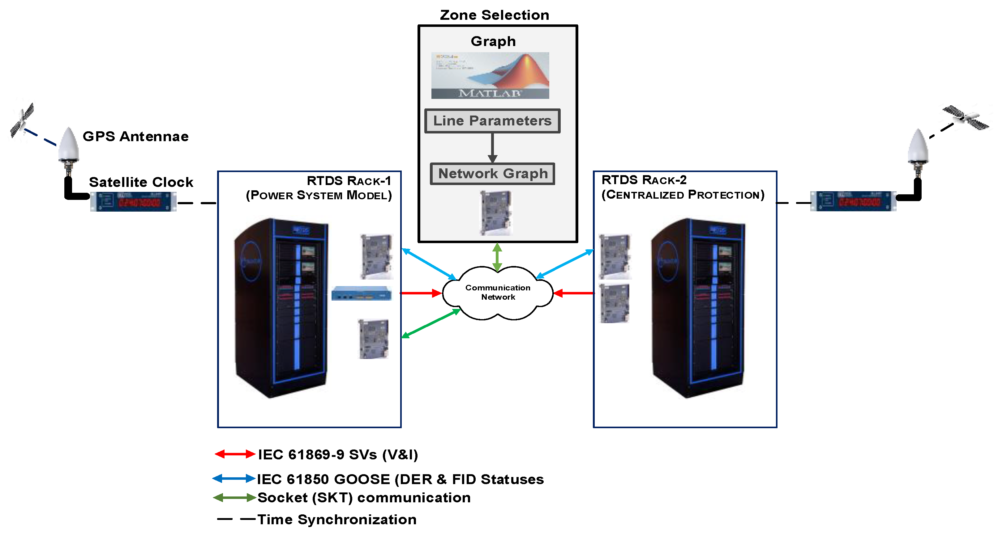
4. Real-Time Implementation

This section describes the proof-of-concept real-time co-simulation platform used for the case studies carried out.

4.1. Hardware Impelementation

Figure 6 shows the architecture of the real-time Proof-of-Concept (PoC) implementation. IEC 61869-9 sampled values from the microgrids are published from the networked microgrids using peer-to-peer communication to the CISP platform located in Microgrid #1. The hardware used is comprised of two co-simulated Real-Time Digital Simulators (RTDS®) racks, GTFPGA module, GTNETx2 cards, GTSYNC cards, GPS satellite clock, and communication network switches as depicted in Figure 7. RTDS® Rack-1 is used for simulating the power system network, while RTDS® Rack-2 serves as the CISP platform for implementing the centralized protection algorithms. Both racks are running asynchronously and are only connected via the GTNETx2 card (i.e., they are mimicking the connection between a power system and the protective relaying scheme).
The interconnected microgrids are modelled on RSCAD software version 5.007 and used in the simulations carried out in this section. An actual communication network consisting of industrial substation-grade switches, IEC 61869-9 sampled values measurements, and IEC 61850 GOOSE messages was used. The communication network was complied with the requirements of IEC 61850 messages and had a typical end-to-end message transmit time of 3 ms. Further information is provided in the proceeding subsections.

4.2. Implementation of the Zone Selection Module

The graphs in the zone selection algorithm proposed in Section 3.1 are designed to automatically update and adapt to the prevailing topology and operating condition of the networked microgrids. A d t h r  threshold value of 3 was used in this study to create subgraphs.
The Zone Selection Module is implemented as a MATLAB-RTDS co-simulation process, rather than in RTDS Rack-2 due to the convenience of programming the network graphs in MATLAB. The inputs to the MATLAB module, which works in near real-time, are the FIDs and DERs statuses published from Rack-1 using the RTDS SKT protocol. The SKT protocol is a client-server socket protocol that can be used for data exchange between the RTDS via a GTNETx2 card (running the SKT protocol) and an external device over a LAN/WAN communication network. In this case, the external device is the computer workstation running MATLAB.
The output of the Zone Selection Module is transmitted as logical bits from MATLAB to the CISP platform (RTDS Rack-2) via the SKT protocol.

4.3. Implementation of the Protection Module

RTDS Rack-2 served as the substation industrial computer for implementing the CISP protection and control modules. Instrument transformers (Current Transformers (CTs) and Voltage Transformers (VTs)) located at the process level of the microgrids served as the inputs to the IMUs. For conventional instrument transformer inputs, IMUs serve as the interface devices for converting the analogue current and voltage signals to digitized SVs, and generally make use of two IEC 61850 Logical Nodes (LNs). These are logical nodes TCTR and TVTR for Current Transformers (CTs) and Voltage Transformers (VTs), respectively. In practical implementation, multiple instances of TCTRs and TVTRs LNs from the networked microgrids will be mapped to the CISP protection algorithms. The protection instances will have pickup thresholds corresponding to each of the protected equipment technologies.
In the PoC testbed implemented, the analogue and binary signals from the RTDS® simulations are converted into optical signals and published over a communication network via the RTDS-GTFPGA device serving as IMUs. Rack-1 publishes to Rack-2 the voltage and current measurements in the networked microgrids using IEC 61869-9 SVs, while the FIDs and DER statuses are published as IEC 61850 GOOSE messages. In comparison to the IEC 61850-9-2 protocol, the IEC 61869-9 has 2 ASDUs and a common sampling rate of 4800 Hz irrespective of the system frequency. A maximum number of 24 quantities are allowed for 100 Mbit/s networks, while no specific limits were defined for 1 Gbit/s networks [36]. The IEC 61869-9 also defines the use of the IEC 61588 Precision Time Protocol (PTP) for merging unit time synchronization.

5. Case Studies and Results

Extensive real-time simulations covering various fault types, fault locations, and operating scenarios (grid-connected and islanded modes) were carried out to test the proposed CISP platform using a modified IEEE 13-node distribution feeder [42] integrated with DERs. The modeling parameters for the DERs are given in Appendix A. The DERs include a hybrid solar PV generation and Battery Energy Storage System (BESS) at Node-634, Doubly-Fed Induction Generator (DFIG) wind turbine generator at Node-675, and a diesel generator at Node-671. Some of the results obtained are presented and discussed in the proceeding subsections.

5.1. Dynamic Zone Selection

The performance of the proposed dynamic zone selection algorithm is demonstrated using the interconnected microgrids created from the IEEE 13-node distribution feeder (Figure 6). Considering the highlighted bus section (Node-632) of the interconnected microgrids in Figure 6, the status of the CBs and DERs are read by the algorithm, and then adjacency matrix and graphs corresponding to this topology are created. Subgraphs are afterwards created for vertices with degrees greater than d t h r .
Subgraphs are basically assigned as bus protection zones. Other protection zones are the paths between subgraphs (line protection zones) and the paths from end nodes to hubs (feeder zones). The vertices and graphs corresponding to the highlighted section are given in Table 4. Figure 8a shows the adjacency matrix and network graph for the steady-state condition, while Figure 8b shows the adjacency matrix and network graph for a circuit breaker (PCC-CB) open scenario.
The edge corresponding to this open condition is highlighted in Figure 8b. This further demonstrates the ability of network graphs to indicate operating conditions, protection and control operation, and system reconfiguration in real-time.
The adjacency matrix of the entire modified IEEE 13-node distribution feeder at steady-state condition is given by Figure 9a, while Figure 9b gives the updated adjacency matrix for a fault condition on line 671-684 resulting in the opening of the CB at Node-671 to clear the fault.
In Figure 9b, the highlighted entries in the matrix columns corresponding to edge 671-684 change from ones to zeros. This also changes the protection zones as the ZF zone between Node-671 and Node-684 no longer exists.
The adjacency matrix for a more complicated example is given in Figure 9c for a scenario in which the CBs at Nodes-633, -645, -646, PV, and BESS are opened.
Table 5 shows the output of the Zone Selection module for these three case studies. Based on the results obtained, the Zone Selection module determines which of the zones will be designated as bus protection zones ( Z B ) and line protection zones. The SCDITE,bus algorithm is automatically applied to Z B  zones, the SCDITE,line and V-ROCOC algorithms are applied to Z F  zones, and the ROCOC algorithm is applied to Z E H  zones.
The initial number of protection zones for case study-1 (steady-state condition) is 13, while the number of protection zones for case study-2 when the circuit breaker for the line between Node 671 to Node 684 is open is 11. The number of protection zones for case study-3 with the circuit breakers for Line 633-684, Line 645-646, PV POI, and BESS POI open is 10.
From the foregoing, it can be inferred that having pre-determined (static) protection zones could cause protection coordination problems especially when a zone is no longer available due to equipment outage or other prevailing conditions. This applies in particular to interlocking, intertripping, and permissive protection schemes where protection systems rely on the receipt of signals from devices at the remote end (other zones) before they can operate.
The number of protection zones obtained by the CISP for the grid-connected mode is 13, while 12 zones were obtained for the islanded mode with the PCC-CB open. A breakdown of the protection zones, the instances of the CISP protection algorithms, and the fault interruption devices per protection zone are given in Table 6. This paper assumes the use of disconnecting-circuit breakers (DCBs) providing the combined functionality of a circuit breaker and a disconnector.

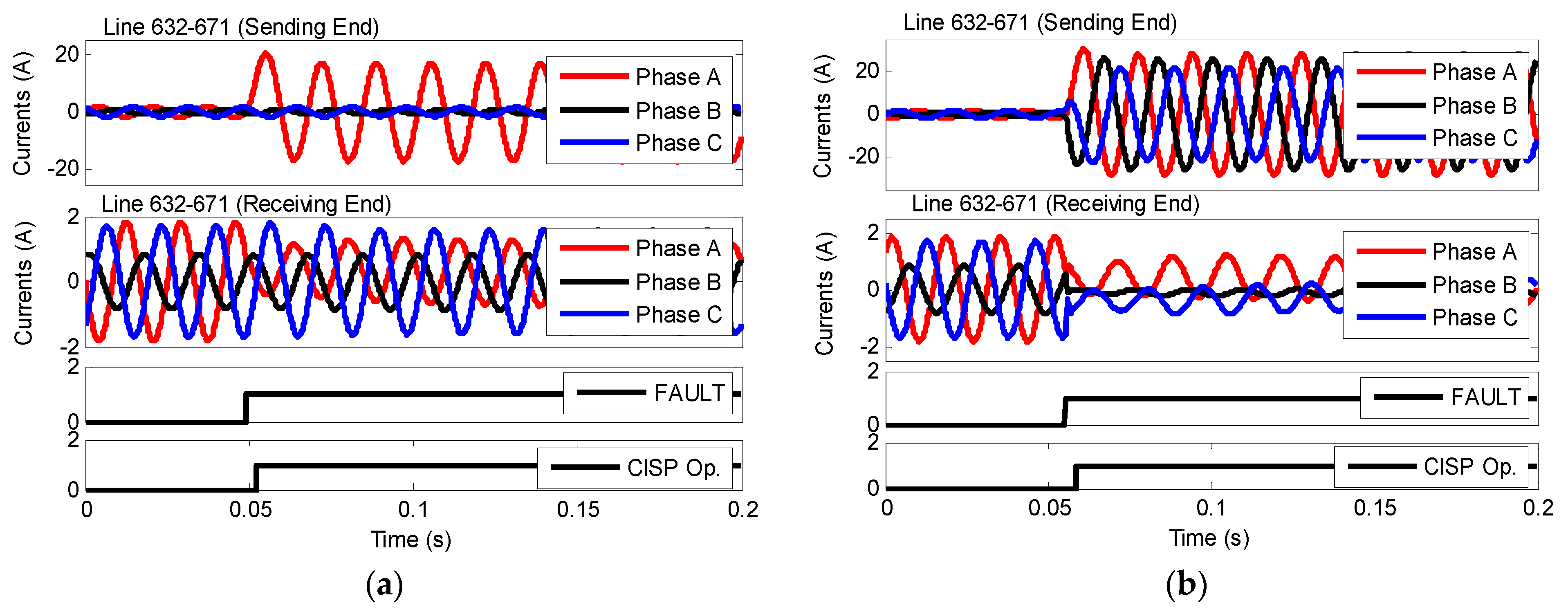
5.2. Case Study-1: Grid-Connected Mode of Operation

Results for this case study are given in Figure 10 for phase and ground faults at 50% of Line 632-671 (F1). The CT and PT parameters used at Line 632-671 are 1200:5 and 2000:1, respectively. An instance of the SCD algorithm was implemented on the CISP platform for this protection zone.
Figure 10a shows the result for Phase A-g fault with a fault resistance of 1.0 Ω and a fault inception angle of 0°. Figure 10b shows the result at the same fault location (F1) for a three-phase fault with a fault resistance of 0.1 Ω and a fault inception angle of 0°.
From Figure 10a, it can be seen that there was no visible change in the line currents (or fault currents) on the receiving end of Line 632-671. The CISP correctly operated with an average operating time (calculated from five trials) of 3.5 ms for ground faults and 3.45 ms for phase faults. Note that the breaker operating time was not taken into consideration in this study. The operating time presented includes the operating time of the CISP platform (communication delay and execution time) based on the real-time hardware-in-the-loop Proof-of-Concept (PoC) testbed that was utilized in this paper. The CISP was able to detect and trip for fault conditions in sub-cycle time of about 4 ms compared to traditional differential protection methods that require the transmission of line current measurements to the other line end. Such differential methods have a typical operating time of about 16 ms.
The PoC consists of a 1 GB/s Ethernet communication network, IEC 61850 sampled values measurements, and GOOSE messages. Hence the latency recorded was minimal.
In practical microgrids, the operating time will depend on the microgrid communication infrastructure and the communication protocol used. Since most microgrids are greenfield stations (with built-in communication networks for the microgrid control system), we would expect a fast communication network to be used, with minimal communication latency.

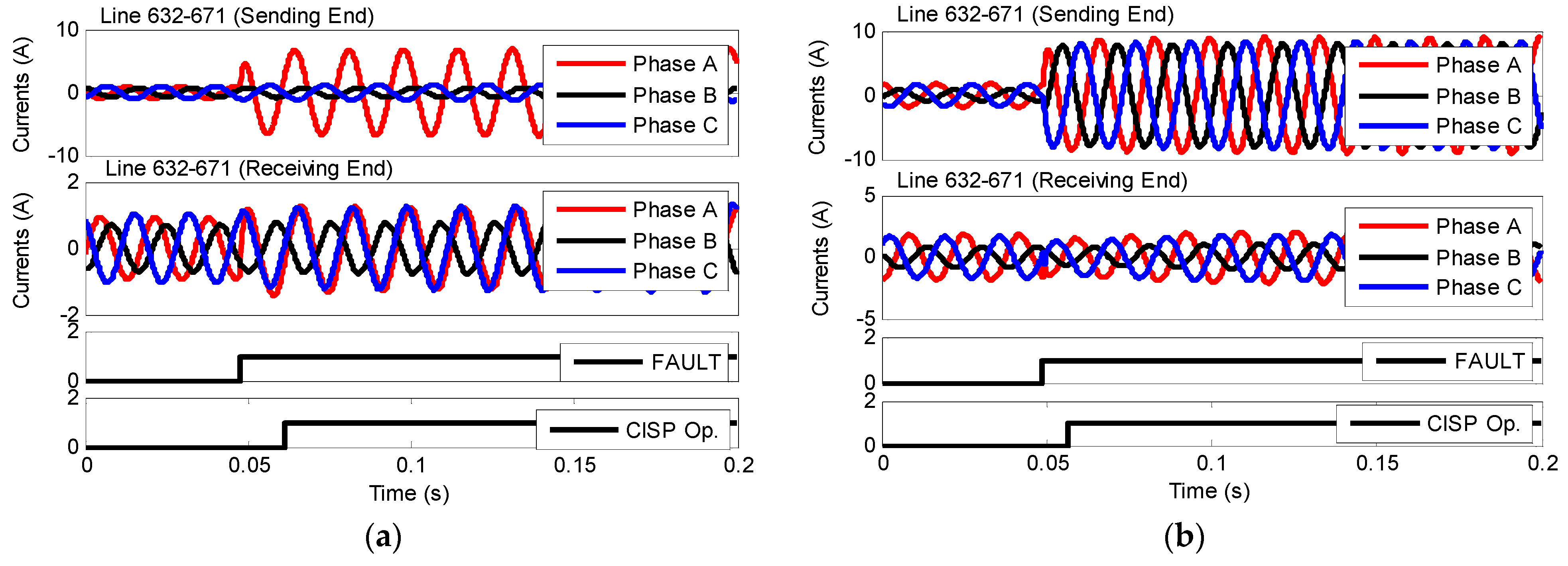
5.3. Case Study–2: Islanded Mode of Operation

This case study presents the results for a similar scenario as in Case Study–1 with the system operating in the islanded mode with the PCC CB open and all the DERs (diesel generator, solar PV, and WTG) in service. Figure 11a shows the fault currents for an A-g fault at F1 with a fault resistance of 1.0 Ω and a fault inception angle of 90°.
Figure 11b shows the result at the same fault location (F1) for a three-phase fault with a fault resistance of 0.1 Ω and a fault inception angle of 90°. Compared to the results in Figure 10a, an infeed can be observed at the remote end of Line 632-671 due to the fault current contribution from downstream DERs. The CISP correctly operated with an average operating time of 13.95 ms for ground faults and 7.65 ms for phase faults. The fault currents for an islanded condition with only inverter-based DERs (PV and BESS) in service were less than twice the load currents due to converter controls action (Figure 12). The average operating time was 7.8 ms for ground faults and 15.75 ms for phase faults. In both scenarios, the CISP platform was reliable and correctly operated by adaptively switching to the slope 3 (K3) differential characteristic of the SCD algorithm. Slope 3 uses a lower minimum differential current ( I D m i n , P )  and slope settings. The traditional differential protection would have failed to detect this scenario.

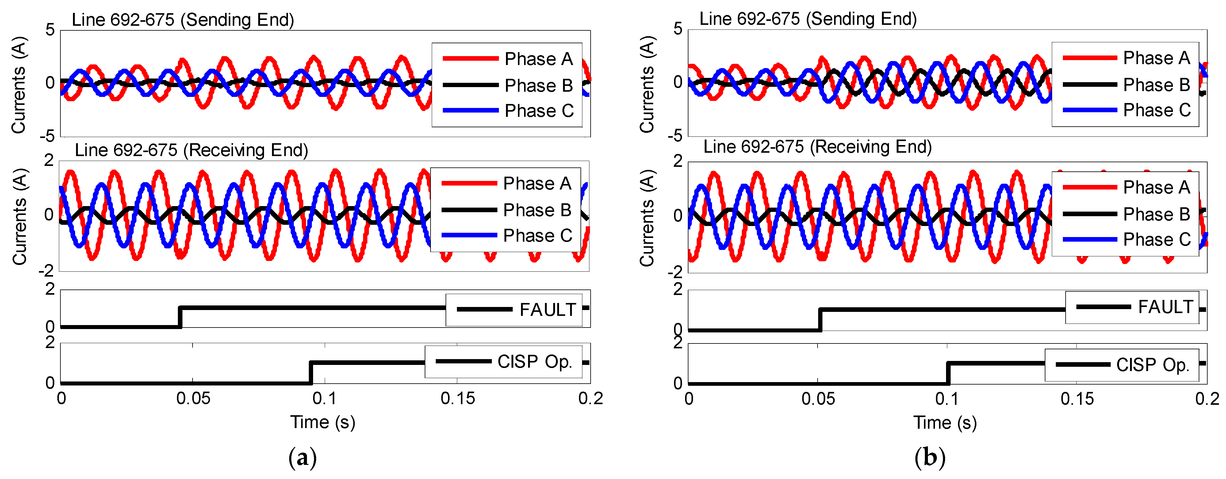
5.4. Case Study–3: Week Infeed Condition

This case study implements an instance of the SCD algorithm and the V-ROCOC algorithm, respectively, on the CISP platform for this protection zone. According to Table 6, Line 692-675 is a line protection zone. Line 692-675 is a weak terminal located remote from any source especially when only the inverter-based DERs (PV and BESS) are in service. Without the DFIG in service, there were no fault currents at the remote end of this line. The traditional differential protection would not detect this fault. However, the CISP platform using the SCD algorithm was sensitive and able to detect this fault, and it had an average operating time of 49.35 ms for ground faults and 49.15 ms for phase faults, as shown in Figure 13.
Based on the proposed zone selection algorithm (shown in Figure 4), an instance of the V–ROCOC algorithm should be implemented from the end node (Node–675) to the nearest hub (Node–671) as indicated in Table 6. However, with the weak infeed at Node–675, the rate of change of currents obtained is negligible. Therefore, the V–ROCOC instance should be applied at the sending end of Line 692-675. Figure 14 shows the result for phase and ground faults at Line 692-675. An average operating time of 13.95 ms was obtained for ground faults, while 2.7 ms was obtained for phase faults using an instance of the V–ROCOC algorithm. These are faster than the operating times obtained for the SCD algorithm. Thus, the V-ROCOC algorithm should be used for weak infeed conditions rather than the SCD algorithm. Note that the results shown in Figure 14 are not sinusoidal because the ROCOC plotted are the output from the sampling and DFT blocks. Also, the operating time for ground faults could be further improved upon by using a much more sensitive ROCOC setting threshold for ground faults.

5.5. Discussion

5.5.1. Results

Results obtained from simulations carried out for various scenarios validate the effectiveness of the zone selection and protective algorithms implemented in the CISP platform. The protection algorithms are simple, selective, and sensitive. Also, the dependability and performance of the CISP platform were not affected even in the islanded mode of operation with a high penetration level of inverter-based DERs. Loss of utility and weak infeeds could be better protected using an instance of the V-ROCOC algorithm. The ITE directional algorithm could also be used in the supervision of the ROCOC algorithm. Alternatively, protection schemes using permissive trip logic based on input quantities from remote microgrid substations could be used on the CISP platform. This would help provide protection coordination and prompt fault clearance in interconnected microgrids with weak infeeds.

5.5.2. Redundant CPC Protection

Redundant CPC protection should be implemented especially for critical applications. The type of redundant protection proposed in this paper is a dual redundant CPC protection. As shown in Figure 2, the redundant CPC has the same features and modules (ZS–Module, P-Module, and A–Module) as the main CPC protection and operates in parallel with the main CPC protection.
Also, the redundant CPC protection could be implemented with a separate set of instrument transformers (CTs, PTs), merging units, circuit breakers, time synchronization, substation batteries, and communication network depending on the utility’s protection philosophy. If the back-up redundant centralized protection fails, overcurrent protection functions configured in merging units could be used as a backup to the redundant CISP platform in order to enhance the reliability of the microgrid. Note that this time-delayed OC protection in the merging units is not coordinated and is only meant to be used for backup unit protection. Also, a redundant communication network should be utilized as a backup against communication failure. Unlike in traditional protection consisting of multiple protective relays, the CISP platform does not require fault current-time coordination with long time delays because the backup CISP platform can operate timely without any further delay.

5.5.3. Field Deployment

The proposed CISP platform can be deployed onto a hardened industrial substation computer, a Real-Time Automation Controller, or onto a relay platform. This would require that the hardware platform be capable of subscribing to, and processing multiple streams of, measurements from merging units in real-time. These measurements could be the regular IEC 61850 sampled values or Routable Sampled Values (R–SV).
Also, the CISP platform used should be capable of handling the computational burden required for real-time subscription of the SV measurements, data processing, execution of the zone selection, protection, and control modules, transmission, and subscription of IEC 61850 (sampled values and GOOSE) messages [35], IEEE C37.118 synchrophasor standard [38], communication network redundancy (PRP and/or HSR) protocols [39], and network-based time synchronization (IEEE 1588 precision time protocol [43]). Furthermore, the software component of the selected CPC hardware platform should be flexible and user-friendly such that the utility is able to upgrade the CPC modules, integrate custom protection algorithms, or add more functionalities in the future without any hardware upgrades. In addition, some functionalities that should be supported include protection algorithms (overload protection, phase and ground overcurrent, voltage protection, and frequency protection), metering, sequence of events, and supervision HMI.
When integrating the CISP platform to an existing IEC 61850 communication network infrastructure, performance testing should be conducted to ensure that the communication network is fast and has adequate bandwidth that can support IEC 61850 sampled values.

5.5.4. Impact of Adverse Communication Network

Depending on the communication network used, communication delays could be constrained to a few acceptable cycles. Thus, the proposed centralized protection platform will provide effective fault clearance without compromising system stability. Adverse communication network Quality of Service (QoS) issues like latency, jitter, losses, bandwidth limitations, and noise could cause the sampled values measurements to arrive late and out of sequence. This could result in the proposed centralized protection platform having a delayed response to faults or not operate at all. Also, the missing data packets could make data concentration difficult. One solution is to have a redundant communication network as mentioned in Section 2.2. For example, the PRP and HSR redundancy protocols would provide a seamless failover in the case of a single point of failure in a communication network. In a case where there is a communication bandwidth limitation, upgrading the utility communication infrastructure will improve the communication network throughput.

6. Conclusions

A CISP platform was proposed in this paper for the protection of networked microgrids or interconnected power systems. The proposed CISP platform automatically determines and updates the protection zones based on the prevailing system topology. Also, the protection algorithms are reliable and adaptive to the prevailing topology and system conditions and do not require the use of multiple local relays. Furthermore, the CISP platform does not require separate protection functions or relay settings groups for the islanded mode or other low fault currents operating conditions. In addition, the proposed SCD, directional ITE, ROCOC, and V–ROCOC algorithms implemented in the CISP platform use only the transients generated during faults. Thus, it is suitable for systems with large penetration levels of inverter-based DERs and low fault current contribution.
The advantage of using centralized protection systems in networked microgrids as proposed in this paper is that multiple protection relays are no longer required. Also, the use of multiple settings groups for various prevailing topologies or operating modes are no longer required. Furthermore, protection coordination between multiple protection relays is eliminated.
The experimental results obtained using a proof-of-concept real-time simulation testbed validate the effectiveness of the proposed CISP platform, and shows that the proposed approach is practical and the performance of the proposed CISP approach is fast, sensitive, secure, and dependable. Also, the low pass filter in the analog front end of the merging units and the DFT applied on the voltage or current signals used by the protection algorithms minimizes the effect of noise or harmonics by effectively attenuating the high-frequency noise or harmonic components from the analog signals. Removing the high-frequency noise and harmonic signals ensures that the analog measurements are accurate especially during low system loading scenarios where the steady-state load current is less than 5% of the nominal current value. Also, removing the noise and harmonic components from an analog signal gives a much cleaner signal that enhances the effectiveness and efficiency of the proposed CISP in detecting and isolating faults irrespective of the system loading scenario.
Although the RTDS® was used in the proof-of-concept testbed to emulate the centralized protection platform, the centralized protection will typically be deployed on an IED or station computer in practical systems. Also, it was shown that the deployed centralized protection can be successfully integrated using IEC 61850 infrastructure. The reliable operation of the proposed centralized protection requires a communication network with little or no latency that satisfies the message transmit time requirements defined in [35]. Although communication delay could cause delayed fault clearing by the proposed centralized protection, this does not adversely affect the protection coordination in the proposed centralized protection as all protection decisions are made by the centralized protection.
Finally, the elimination of numerous hard-wired signals by IEC 61850 GOOSE messages and sampled values, and the replacement of multiple protective devices with a central protection device, possibly duplicated to provide redundancy, is expected to be a more cost-effective solution. Moreover, centralized protection supports the increasing digitization drive in electric power utilities and can easily be incorporated in the protection design of greenfield microgrids or retrofitted in brownfield microgrids.
Future work will consider the impact of pervasive communication network QoS like latency, jitter, losses, bandwidth limitations, and noise on the proposed centralized protection platform. This will be performed using a communication co-simulation platform integrated with a power system and a centralized protection platform. This would allow us to actually emulate QoS issues on an actual communication network and also test the impact of communication QoS issues on Routable–GOOSE (R–GOOSE) and Routable–Sampled Values (R–SVs) measurements.

Author Contributions

Conceptualization, A.C.A., A.D.R., D.O. and P.F.; software, A.C.A.; validation, A.C.A. and A.D.R.; investigation, A.C.A., A.D.R., D.O. and P.F.; resources, A.D.R., D.O. and P.F.; writing—original draft preparation, A.C.A. and A.D.R.; writing—review and editing, A.C.A., A.D.R., D.O. and P.F.; supervision, A.D.R., D.O. and P.F.; project administration, A.C.A. and A.D.R.; funding acquisition, A.D.R. and P.F. All authors have read and agreed to the published version of the manuscript.

Funding

This work was supported by Mitacs through the Mitacs Accelerate program.

Data Availability Statement

The data presented in this study are available on request from the corresponding author. The data are not publicly available due to the term confidentiality existing in the project.

Acknowledgments

The authors would like to thank Mitacs Accelerate program, Canada and RTDS Technologies Inc., Winnipeg, Canada for the financial support provided for this research.

Conflicts of Interest

The authors declare no conflict of interest.

Appendix A

Appendix A.1. Parameters of the IEEE 13 Node Test Distribution System

IEEE 13 node test distribution system [41].

Appendix A.2. Parameters of Battery Energy Storage System (BESS)

ParameterSetting
Capacity (MW)2.0
Battery typeMin/Rincon-Mora
Number of cells in series per stack (EA)250
Number of stacks in parallel (EA)250
Capacity of a single cell (AH)0.85
Initial state of charge (%)85
Capacity fading factor (%)0

Appendix A.3. Parameters of Solar PV

ParameterSetting
Solar cell modelSingle diode five parameter model
Solar cell semiconductor materialMonocrystalline
Number of series connected cells per string per module36
Number of parallel strings of cells1
Open circuit voltage (V)21.7
Short circuit current (A)3.35
Voltage at Pmax (V)17.4
Current at Pmax (A)3.05
Reference temperature at standard test conditions (°C)25
Number of modules in series115
Number of modules in parallel66

Appendix A.4. Parameters of DFIG Wind Farm

ParameterSetting
Induction Generator
      Inertia constant (MWs/MVA)0.78
      Rated stator L-L voltage (V)690
      Rated MVA (MVA)2.2
      Rated frequency (Hz)60
      Stator resistance (p.u.)0.00462
      Stator leakage reactance (p.u.)0.102
      Unsaturated magnetizing reactance (p.u.)4.348
      First cage rotor resistance (p.u.)0.0060
      First cage rotor leakage reactance (p.u.)0.08596
Wind Turbine
      Rated turbine power (MW)2.0
      PU Generator speed (p.u.)1.2
      Rated wind speed (m/s)12.0
      Cut-in wind speed (m/s)6.0

Appendix A.5. Parameters of Diesel Generator

ParameterSetting
Rated MVA of the machine (MVA)2.0
Rated L-L voltage (V)480
Base angular frequency (Hz)60
Inertia constant (MWs/MVA)3.03
Stator leakage reactance (p.u.)0.130
D-axis unsaturated reactance (p.u.)1.79
D-axis unsaturated transient reactance (p.u.)0.169
D-axis unsaturated sub-transient reactance (p.u.)0.135
Q-axis unsaturated reactance (p.u.)1.71
Q-axis unsaturated transient reactance (p.u.)0.228
Q-axis unsaturated sub-transient reactance (p.u.)0.2
Stator resistance (p.u.)0.002
D-axis unsaturated transient open time constant (s)4.3
D-axis unsaturated sub-transient open time constant (s)0.032
Q-axis unsaturated transient open time constant (s)0.85
Q-axis unsaturated sub-transient open time constant (s)0.05

References

  1. Jones, D.; Kumm, J.J. Future distribution feeder protection using directional overcurrent elements. IEEE Trans. Ind. Appl. 2014, 50, 1385–1390. [Google Scholar] [CrossRef]
  2. Hooshyar, A.; Iravani, R. A New Directional Element for Microgrid Protection. IEEE Trans. Smart Grid 2018, 9, 6862–6876. [Google Scholar] [CrossRef]
  3. Yazdaninejadi, A.; Golshannavaz, S.; Nazarpour, D.; Teimourzadeh, S.; Aminifar, F. Dual-Setting Directional Overcurrent Relays for Protecting Automated Distribution Networks. IEEE Trans. Ind. Inform. 2018, 15, 730–740. [Google Scholar] [CrossRef]
  4. Muda, H.; Jena, P. Superimposed Adaptive Sequence Current Based Microgrid Protection: A New Technique. IEEE Trans. Power Deliv. 2017, 32, 757–767. [Google Scholar] [CrossRef]
  5. Saleh, K.A.; Mehrizi-Sani, A. Harmonic Directional Overcurrent Relay for Islanded Microgrids with Inverter-Based DGs. IEEE Syst. J. 2021, 15, 2720–2731. [Google Scholar] [CrossRef]
  6. Sortomme, E.; Venkata, S.S.; Mitra, J. Microgrid Protection Using Communication-Assisted Digital Relays. IEEE Trans. Power Deliv. 2010, 25, 2789–2796. [Google Scholar] [CrossRef]
  7. Yuan, C.; Haj-ahmed, M.A.; Illindala, M.A. Protection Strategies for Medium-Voltage Direct-Current Microgrid at a Remote Area Mine Site. IEEE Trans. Ind. Appl. 2015, 51, 2846–2853. [Google Scholar] [CrossRef]
  8. Gao, H.; Li, J.; Xu, B. Principle and implementation of current differential protection in distribution networks with High Penetration of DGs. IEEE Trans. Power Deliv. 2017, 32, 565–574. [Google Scholar] [CrossRef]
  9. Arunan, A.; Sirojan, T.; Ravishankar, J.; Ambikairajah, E. Real-time adaptive differential feature-based protection scheme for IMGs using Edge Computing. IEEE Syst. J. 2021, 15, 1318–1328. [Google Scholar] [CrossRef]
  10. Dubey, K.; Jena, P. Impedance Angle-Based Differential Protection Scheme for Microgrid Feeders. IEEE Syst. J. 2021, 15, 3291–3300. [Google Scholar] [CrossRef]
  11. Huang, W.; Nengling, T.; Zheng, X.; Fan, C.; Yang, X.; Kirby, B.J. An impedance protection scheme for feeders of active distribution networks. IEEE Trans. Power Deliv. 2014, 25, 1591–1602. [Google Scholar] [CrossRef]
  12. Redfern, M.A.; Al-Nasseri, H. Protection of microgrids dominated by distributed generation using solid state converters. In Proceedings of the IET 9th International Conference on Developments in Power Systems Protection (DPSP 2008), Glasgow, Scotland, 17–20 March 2008; pp. 670–674. [Google Scholar] [CrossRef]
  13. Al-Nasseri, H.; Redfern, M.A. Harmonics content based protection scheme for micro-grids dominated by solid state converters. In Proceedings of the 12th International Middle-East Power System Conference, Aswan, Egypt, 12–15 March 2008; pp. 50–56. [Google Scholar] [CrossRef]
  14. Vieira, J.C.; Freitas, W.; Xu, W.; Morelato, A. Performance of frequency relays for distributed generation protection. IEEE Trans. Power Deliv. 2006, 21, 1120–1127. [Google Scholar] [CrossRef]
  15. Li, X.; Dysko, A.; Burt, G.M. Travelling wave-based protection scheme for inverter-dominated microgrid using mathematical morphology. IEEE Trans. Smart Grid 2014, 5, 2211–2218. [Google Scholar] [CrossRef]
  16. Zarei, S.F.; Parniani, M.A. Comprehensive digital protection scheme for low-voltage microgrids with inverter-based and conventional distributed generations. IEEE Trans. Power Deliv. 2017, 32, 441–452. [Google Scholar] [CrossRef]
  17. Soleimanisardoo, A.; Karegar, H.K.; Zeineldin, H.H. Differential frequency protection scheme based on off-nominal frequency injections for inverter-based islanded microgrids. IEEE Trans. Smart Grid 2019, 10, 2107–2114. [Google Scholar] [CrossRef]
  18. Gururani, A.; Mohanty, S.R.; Mohanta, J.C. Microgrid protection using Hilbert–Huang transform based-differential scheme. IET Gener. Transm. Distrib. 2016, 10, 3707–3716. [Google Scholar] [CrossRef]
  19. Reiz, C.; Leite, J.B. Optimal Coordination of Protective Devices in Distribution Networks with Distributed Energy Resources and Microgrids. IEEE Access 2022, 10, 99584–99594. [Google Scholar] [CrossRef]
  20. Dehghanpour, E.; Karegar, H.K.; Kheirollahi, R.; Soleymani, T. Optimal coordination of directional overcurrent relays in microgrids by using cuckoo-linear optimization. IEEE Trans. Smart Grid 2018, 9, 1365–1375. [Google Scholar] [CrossRef]
  21. Sharaf, H.M.; Zeineldin, H.H.; El-Saadany, H. Protection coordination for microgrids with grid-connected and islanded capabilities using communication assisted dual setting directional overcurrent relays. IEEE Trans. Smart Grid 2018, 9, 143–151. [Google Scholar] [CrossRef]
  22. Usama, M.; Mokhlis, H.; Moghavvemi, M.; Mansor, N.N.; Alotaibi, M.A.; Muhammad, M.A.; Bajwa, A.A. A Comprehensive Review on Protection Strategies to Mitigate the Impact of Renewable Energy Sources on Interconnected Distribution Networks. IEEE Access 2021, 9, 35740–35765. [Google Scholar] [CrossRef]
  23. Eissa, M.M. A novel centralized wide area protection “CWAP” in phase portrait based on pilot wire including phase comparison. IEEE Trans. Smart Grid 2018, 10, 2671–2682. [Google Scholar] [CrossRef]
  24. Bo, Z.Q.; Han, M.; Klimek, A.; Zhang, B.H.; He, J.H.; Dong, X.Z. A centralized protection scheme based on combined positional protection techniques. In Proceedings of the 2009 IEEE Power & Energy Society General Meeting, Calgary, AB, Canada, 26–30 July 2009; pp. 1–6. [Google Scholar] [CrossRef]
  25. Sakis Meliopoulos, A.P.; Cokkinides, G.J.; Myrda, P.; Liu, Y.; Fan, R.; Sun, L.; Huang, R.; Tan, Z. Dynamic state estimation-based protection: Status and promise. IEEE Trans. Power Deliv. 2017, 32, 320–330. [Google Scholar] [CrossRef]
  26. Albinali, H.F.; Sakis Meliopoulos, A.P. Resilient protection system through centralized substation protection. IEEE Trans. Power Deliv. 2018, 33, 1418–1427. [Google Scholar] [CrossRef]
  27. Monadi, M.; Gavriluta, C.; Luna, A.; Candela, J.I.; Rodriguez, P. Centralized protection strategy for medium voltage DC microgrid. IEEE Trans. Power Deliv. 2017, 32, 430–440. [Google Scholar] [CrossRef]
  28. Ustun, T.; Ozansoy, C.; Zayegh, A. Modeling of a centralized microgrid protection system and distributed energy resources according to IEC 61850-7-420. IEEE Trans. Power Syst. 2012, 27, 1560–1567. [Google Scholar] [CrossRef]
  29. Liu, Y.; Gao, H.; Gao, W.; Peng, F. Development of a substation-area backup protective relay for smart substation. IEEE Trans. Smart Grid 2017, 8, 2544–2553. [Google Scholar] [CrossRef]
  30. Choi, S.; Sakis Meliopoulos, A.P. Effective real-time operation and protection scheme of microgrids using distributed dynamic state estimation. IEEE Trans. Power Deliv. 2017, 32, 504–514. [Google Scholar] [CrossRef]
  31. Ma, J.; Xiang, X.; Zhang, R.; Li, P.; Liu, J.; Thorp, J.S. Regional protection scheme for distribution network based on logical information. IET Gener. Transm. Distrib. 2017, 11, 4314–4323. [Google Scholar] [CrossRef]
  32. Seyedi, Y.; Karimi, H. Coordinated protection and control based on synchrophasor data processing in smart distribution network. IEEE Trans. Power Syst. 2018, 33, 634–645. [Google Scholar] [CrossRef]
  33. Kannaian, R.B.; Joseph, B.B.; Ramachandran, R.P. An adaptive centralized protection and relay coordination algorithm for Microgrid. Energies 2023, 16, 4820. [Google Scholar] [CrossRef]
  34. Adewole, A.C.; Rajapakse, A.D.; Ouellette, D.; Forsyth, P. Protection of Active Distribution Networks Incorporating Microgrids with Multi-Technology Distributed Energy Resources. Electr. Power Syst. Res. 2022, 202, 107575. [Google Scholar] [CrossRef]
  35. IEC 61850-8-1; Communication Networks and Systems for Power Utility Automation—Part 8-1: Specific Communication Service Mapping (SCSM); Mappings to MMS (ISO 9506-1 and ISO 9506-2) and to ISO/IEC 8802-3. International Electrotechnical Commission: Geneva, Switzerland, 2011.
  36. IEC 61869-9; Instrument Transformers—Part 9: Digital Interface for Instrument Transformers. International Electrotechnical Commission: Geneva, Switzerland, 2016.
  37. IEEE Power System Relaying Committee. Centralized Substation Protection and Control WG K15 Report. December 2015. Available online: https://www.pes-psrc.org/kb/report/020.pdf (accessed on 8 October 2023).
  38. IEEE Std C37.118.1-2011 (Revision of IEEE Std C37.118-2005); IEEE Standard for Synchrophasor Measurements for Power Systems. IEEE: New York, NY, USA, 2011; pp. 1–61. [CrossRef]
  39. IEC 62439-3:2016; Industrial Communication Networks—High Availability Automation Networks—Part 3: Parallel Redundancy Protocol (PRP) and High-Availability Seamless Redundancy (HSR). International Electrotechnical Commission: Geneva, Switzerland, 2016.
  40. SEL-401 Protection, Automation, and Control Merging Unit Instruction Manual; Schweitzer Engineering Laboratory: Pullman, WA, USA, 2021.
  41. Sedgewick, R. Algorithms in C—Part 5 Graphs Algorithms; Addison-Wesley: Boston, MA, USA, 2002. [Google Scholar]
  42. IEEE 13-Node Test Feeder, IEEE PES Test Feeder. Available online: https://site.ieee.org/pes-testfeeders/resources/ (accessed on 17 January 2023).
  43. IEEE Std 1588-2019 (Revision of IEEE Std 1588-2008); IEEE Standard for a Precision Clock Synchronization Protocol for Networked Measurement and Control Systems. IEEE: New York, NY, USA, 2020; pp. 1–499. [CrossRef]
Figure 1. Substation CPC architecture (Architecture 5a, [37]).
Energies 16 07080 g001
Figure 2. Proposed CPC architecture for networked microgrids.
Energies 16 07080 g002
Figure 3. Flowchart of the proposed centralized protection.
Energies 16 07080 g003
Figure 4. Flowchart of the zone selection algorithm.
Energies 16 07080 g004
Figure 5. Proposed adaptive differential protection characteristics.
Energies 16 07080 g005
Figure 6. Networked microgrids real-time implementation testbed.
Energies 16 07080 g006
Figure 7. Proof-of-concept co-simulation real-time testbed.
Energies 16 07080 g007
Figure 8. Adjacency matrices and graphs for (a) steady-state condition, (b) circuit breaker open scenario.
Energies 16 07080 g008
Figure 9. Adjacency matrices and graphs for (a) steady state condition, (b) open CB at Line 671-684, (c) open CBs at Line 645-646, line 633-634, PV, and BESS.
Energies 16 07080 g009
Figure 10. Grid-connected mode for faults at F1 (a) A-g fault, (b) three-phase fault.
Energies 16 07080 g010
Figure 11. Islanded mode (with DFIG, PV, BESS, Diesel generator online) for faults at F1 (a) A-g fault, (b) three-phase fault.
Energies 16 07080 g011
Figure 12. Islanded mode (with inverter-based DERs only) for faults at F1 (a) A-g fault, (b) three-phase fault.
Energies 16 07080 g012
Figure 13. Weak infeed scenario for faults at F2 using the SCD algorithm (a) A-g fault, (b) three-phase fault.
Energies 16 07080 g013
Figure 14. Weak infeed scenario for faults at F2 using the ROCOC algorithm (a) A-g fault, (b) three-phase fault.
Energies 16 07080 g014
Table 1. Summary of the related literature on centralized protection.
ReferencesScopeLimitations/Disadvantages
[23]Protection of traditional grid using a combination of current differential and phase comparison schemes.Traditional protection algorithms were used. These could fail for microgrids (MGs) with topology changes, DER changes, and varying fault current levels.
[24]High frequency fault current transient detection for transmission lines in traditional grids.Proposed method might fail when used in MGs with topology changes, DER changes, and varying fault current levels.
[25,26,30]Model-based dynamic state estimation for the protection of substation assets.Performance of this method depends on the accuracy of the developed model of the power system components.
[27]Differential protection relays per DC sub-microgrid supervised by a centralized protection unit.Requires multiple local distributed protection relays. These relays could send the wrong decision or conflicting information to the centralized protection unit.
[28]Communication-based protection using the IEC 61850 Standard. Depends on the information received from multiple distributed protection devices.
[29]Differential protection algorithm with an adaptive restraint characteristic.This method is not suitable for primary protection and is limited to backup protection only. Could fail for microgrids with topological changes, DER changes, and varying fault current levels.
[31]Regional protection scheme based on overcurrent (OC) protection devices.Performance depends on the accuracy of the logical information received from multiple protection devices. Also, multiple OC settings per relay are required to provide a 100% protection coverage of a single line length.
[32]Based on persistent overvoltage and/or frequency disturbance for microgrid.Only line protection was considered. The practicability of the proposed method was not demonstrated.
[33]Distributed overcurrent protective relays supervised by a microgrid central controller (MCC). Performance depends on multiple distributed relays wherein coordination is determined by the MCC. It could be difficult providing time-coordination to multiple relays during fast dynamic system topology changes or operating modes.
Table 2. Description of the graph components.
Graph ComponentDescription
Network graphNetworked Microgrids (MGs)
SubnetworksIndividual MGs
VerticesBusbars, nodes
EdgesCircuit Breakers (CBs), disconnectors (switches), CTs, CB-CT branches, fuses, power transformers
Subgraphs (ZB)Vertices with degree d(v) > dthr.
Shortest path (ZF)Path between subgraphs
MG Diameter (ZEH)Path between end vertices in the MGs and hubs
Table 3. Protection algorithms per protection zone.
Zone TypeProtection Algorithms
ZB zoneSCDITE,bus
ZF zoneSCDITE,line, V-ROCOC
ZEH zoneV-ROCOC, ROCOC
Table 4. Graph example detailing vertices and edges.
Graph ComponentSubstation Components
VerticesNode 650, Node 632, Node 633, Node 634, Node 645, Node 646
EdgesE1, E2, E3, E4, E5
Table 5. Protection zones for some scenarios.
Case StudyNo. of Prot. ZonesProtection Zones
Case study-113ZB: {632,671,645,633}, {671,680,684,692}, {684,611,671,652}
ZEH: {632-671}, {684-671}
ZF: {All end nodes-to-nearest hub}
Case study-211ZB: {632,671,645,633}, {671,680,684,692}
ZEH: {632-671}
ZF: {All end nodes-to-nearest hub}
Case study-310ZB: {632,671,645,633}, {671,680,684,692}
ZEH: {632-671}
ZF: {All end nodes-to-nearest hub}
Table 6. Protection algorithms implemented at each protection zone.
Protection ZonesZone TypeProtection AlgorithmsFIDs
Node 632
Feeders {632,671,645,633}
ZB zoneSCDITE,busS1–3A, S1–3B, S1–3C, S1–3D
Node 671
Feeders {671,680,684,692},
ZB zoneSCDITE,busS2–3A, S2–3B, S2–3C, S2–3D
Node 684
Feeders {684,611,671,652}
ZB zoneSCDITE,busS2–2A, S2–2B, S2–2C
Line 632-671ZF zoneSCDITE,line,V–ROCOCS1–3C, S2–3A
Line 684-671ZF zoneSCDITE,line, V–ROCOCS2–2C, S2–3B
Line 646-632ZEH zoneV–ROCOC, ROCOCS1–1, S1–2A, S1–2B, S1–3B
Line 634-632ZEH zoneV–ROCOC, ROCOCS1–3D, S1–4A, S1–4B, S1–5
Line 611-684ZEH zoneV–ROCOC, ROCOCS2–1, S2–2A
Line 652-684ZEH zoneV–ROCOC, ROCOCS2–2B, S2–4
Line 680-671ZEH zoneV–ROCOC, ROCOCS2–3C, S2–5
Line 675-671ZEH zoneV–ROCOC, ROCOCS2–3D, S3–1A, S3–1B, S3–2
Line 650-632ZEH zoneV–ROCOC, ROCOCCB–PCC, S1–3A
Disclaimer/Publisher’s Note: The statements, opinions and data contained in all publications are solely those of the individual author(s) and contributor(s) and not of MDPI and/or the editor(s). MDPI and/or the editor(s) disclaim responsibility for any injury to people or property resulting from any ideas, methods, instructions or products referred to in the content.

