
Study of the Effects of Regenerative Braking System on a Hybrid Diagnostic Train

 , , , and
Abstract
:1. Introduction
Literature Review on Electric Regenerative Braking in Rail Vehicles
2. Materials and Methods
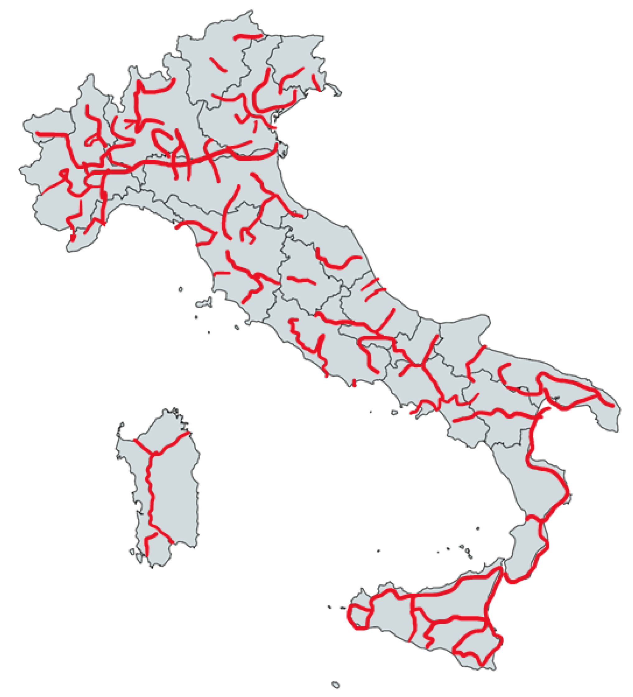
2.1. Case Study
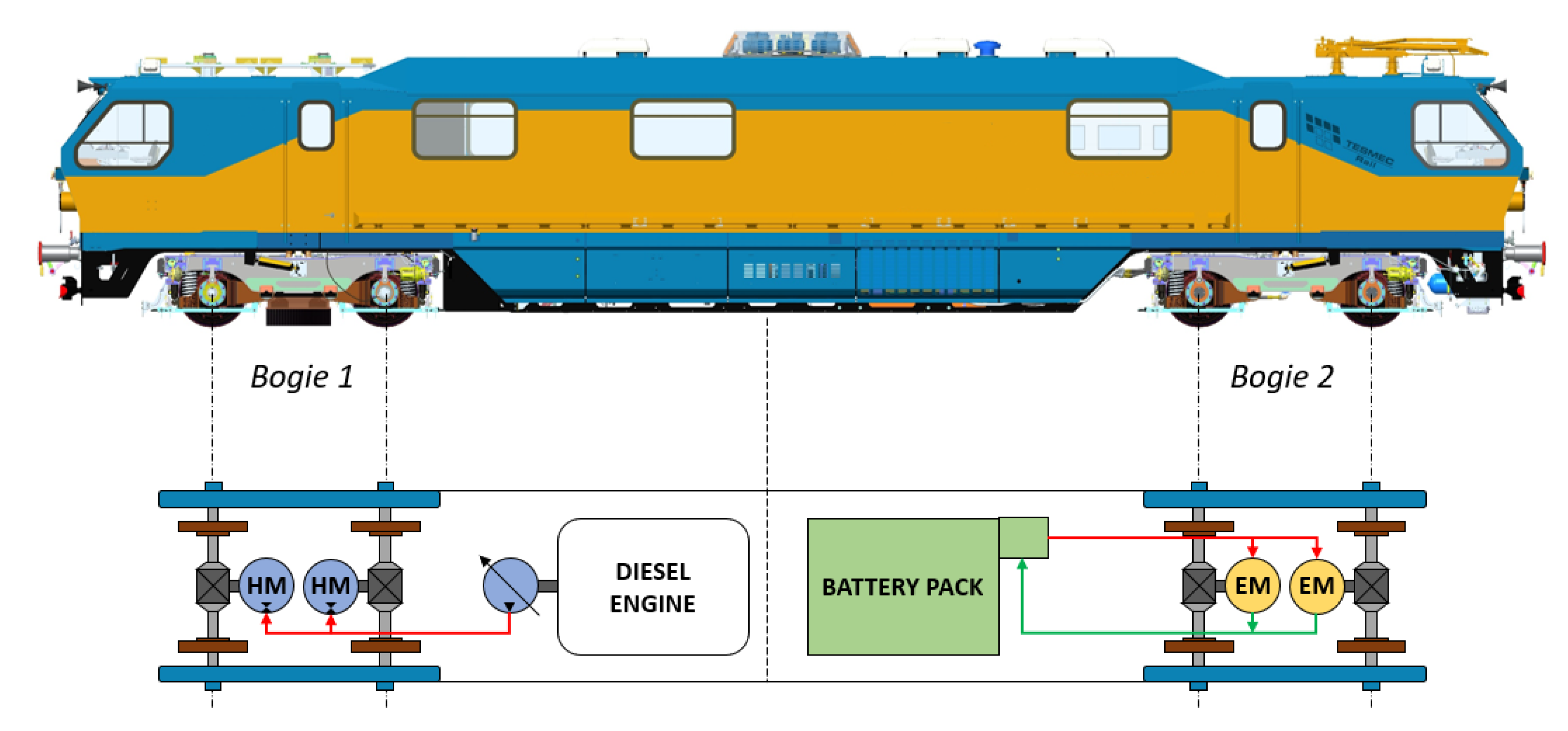
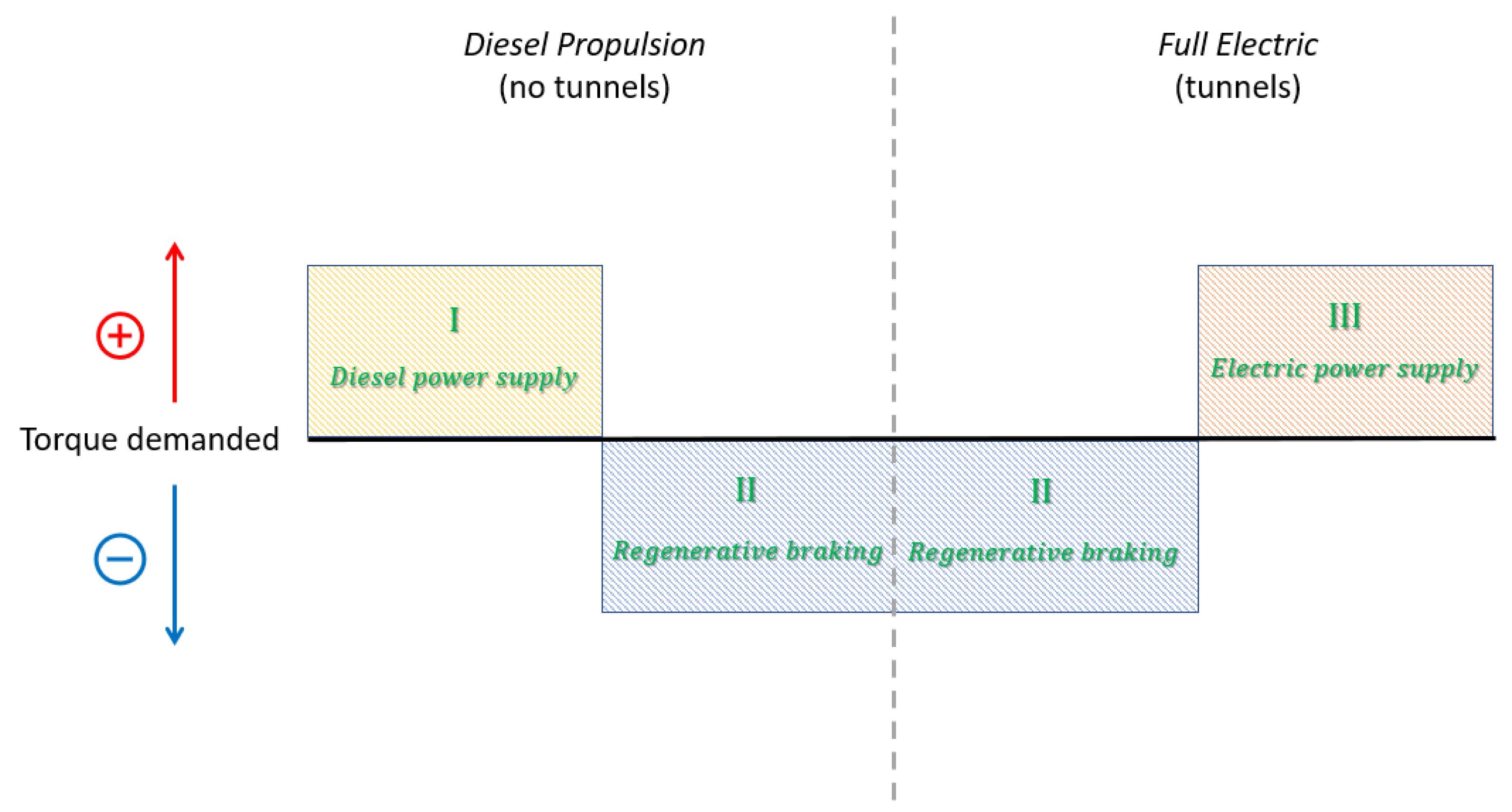
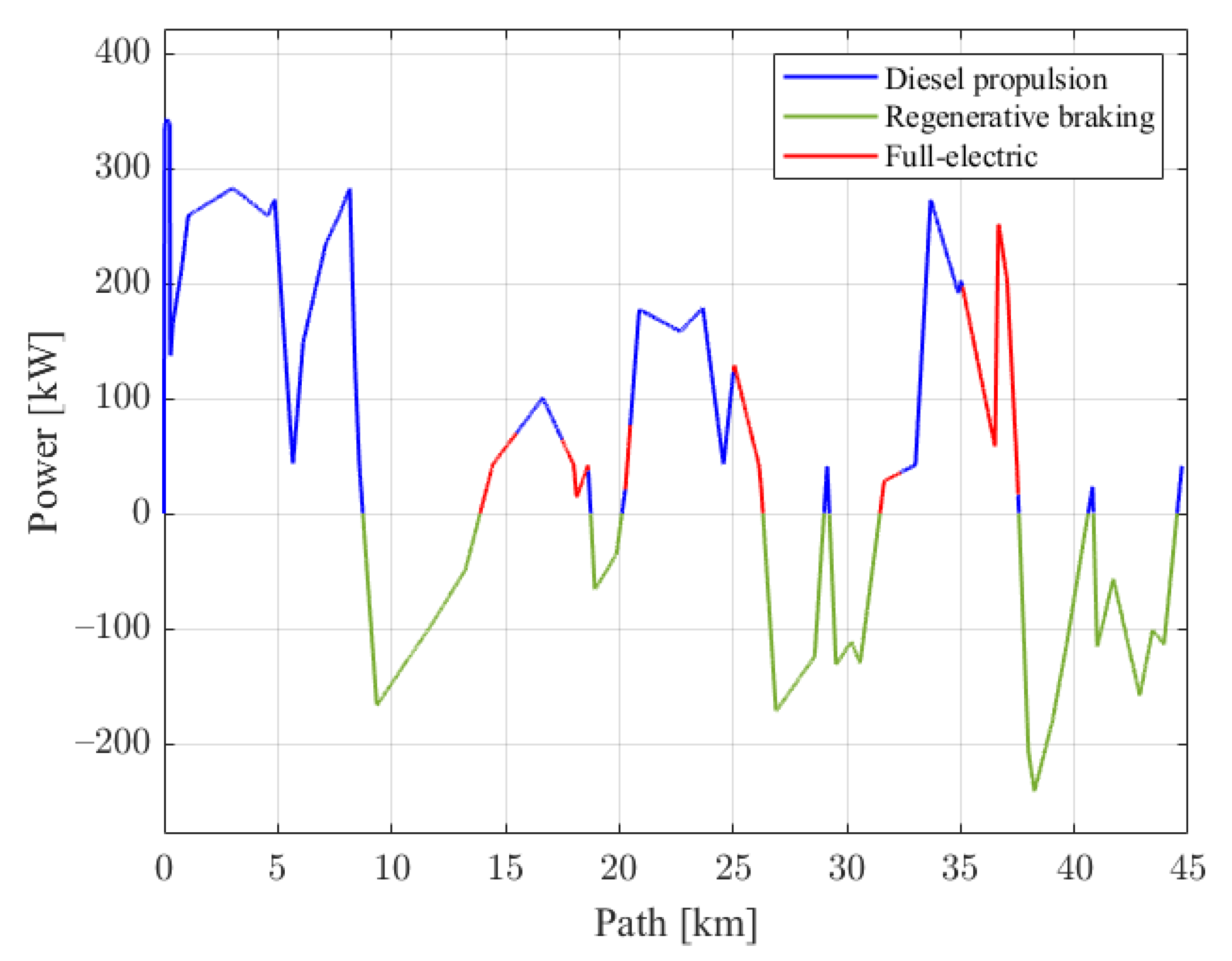
- Diesel propulsion, provided outside the tunnels for positive torque request;
- Regenerative braking, referred to any case of braking torque demanded, provided by the electric motors independently from the propulsion system in use;
- Full-electric, provided in traction phases when the train pass through a tunnel.
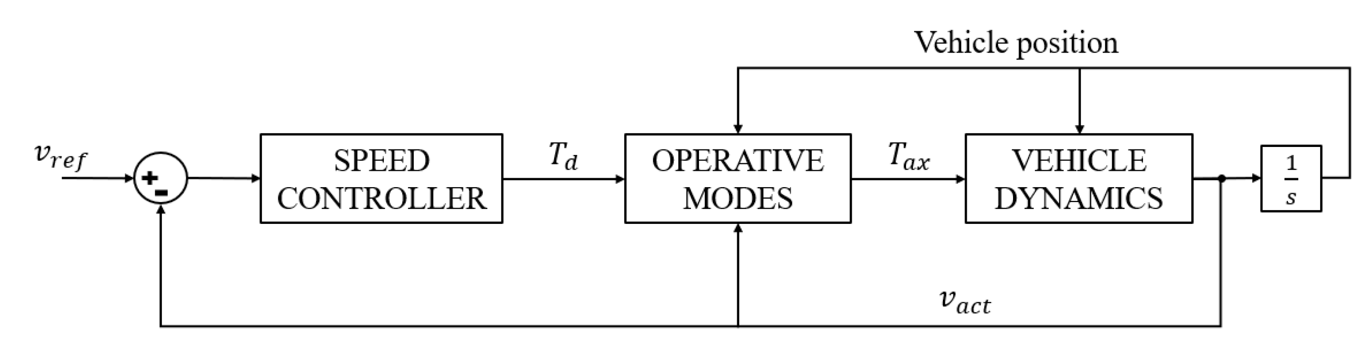
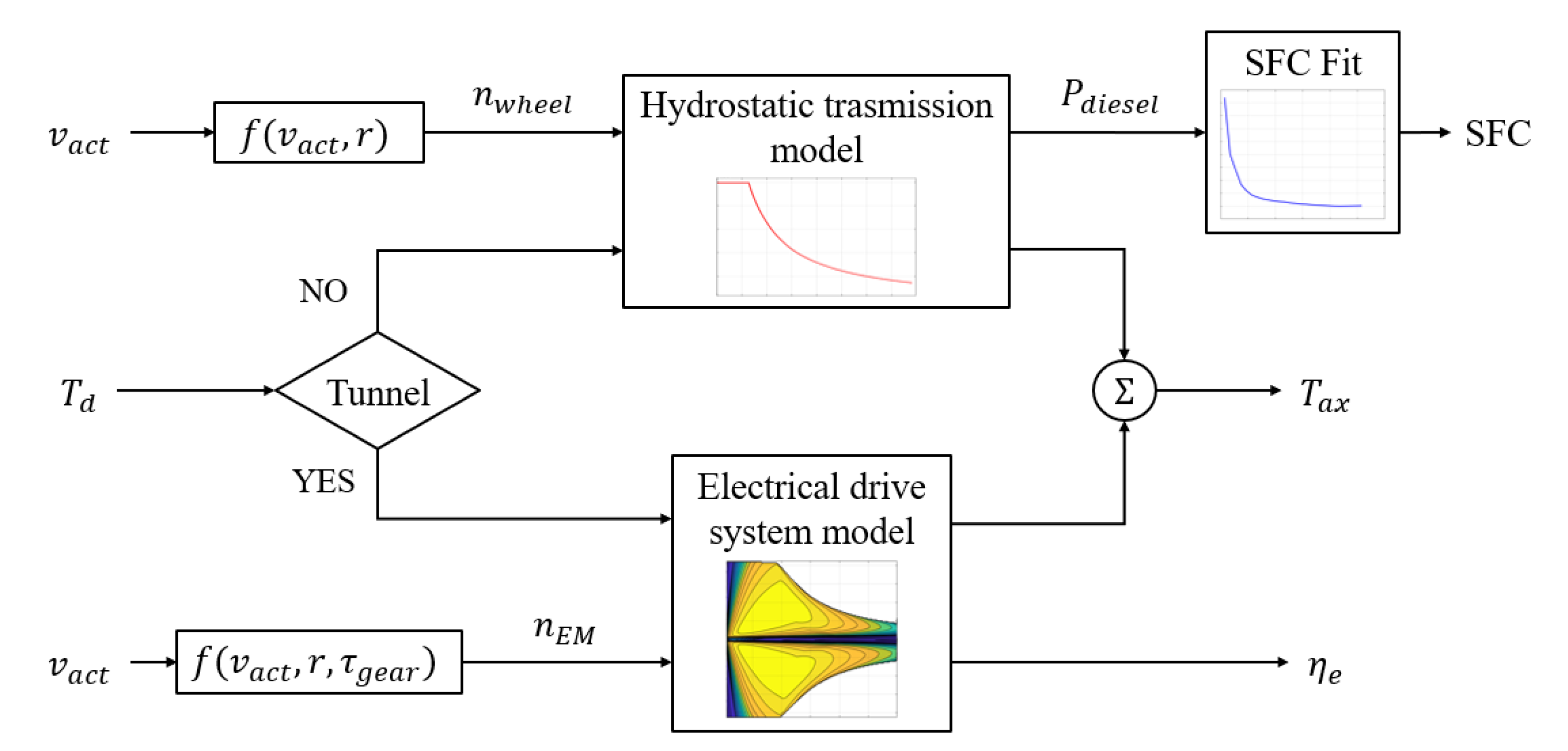
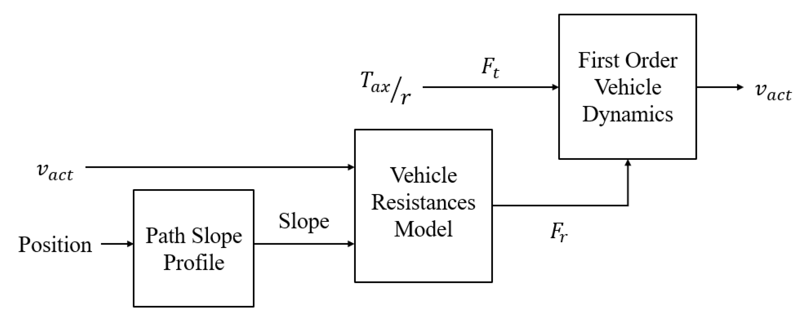
2.2. Proposed Model
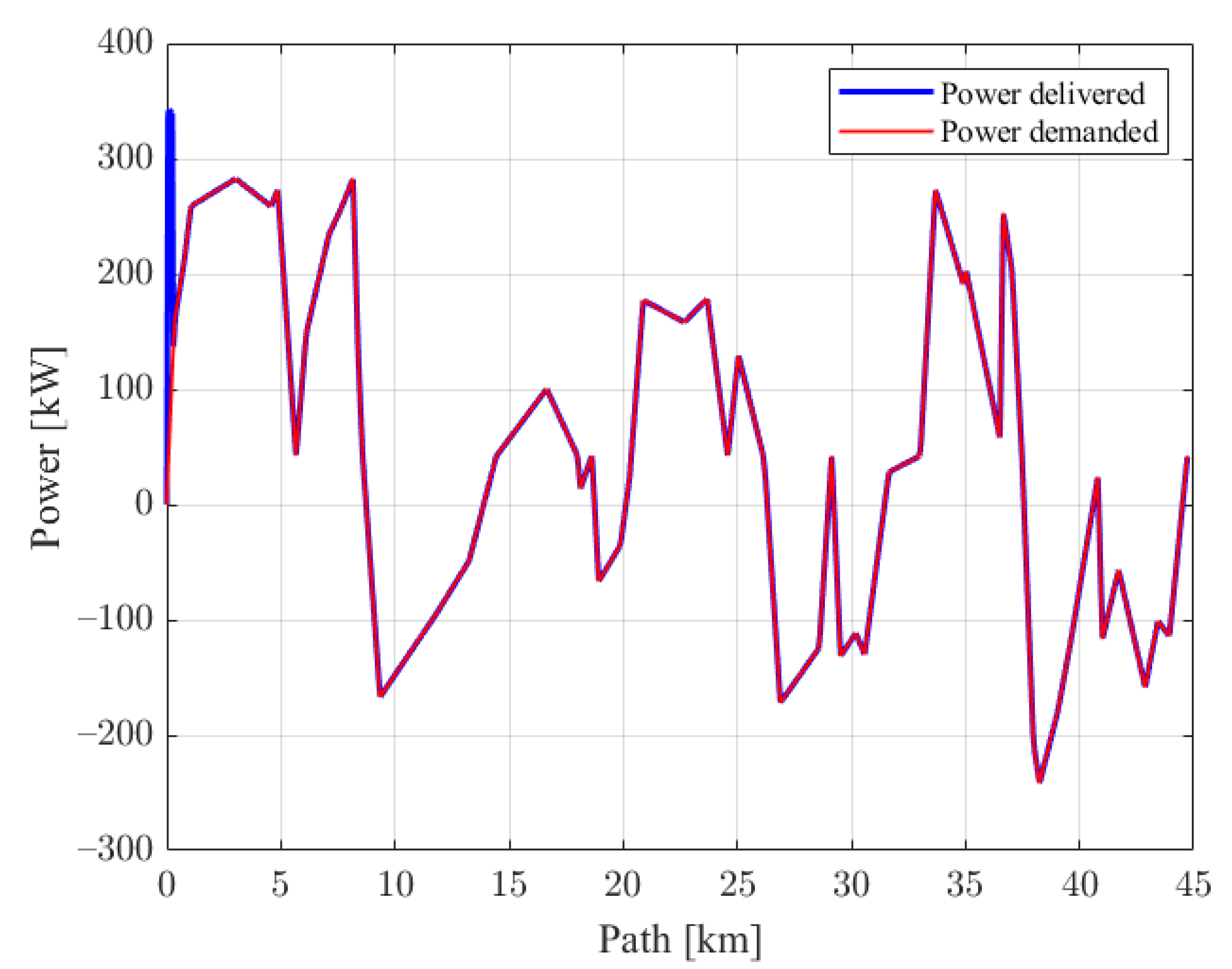
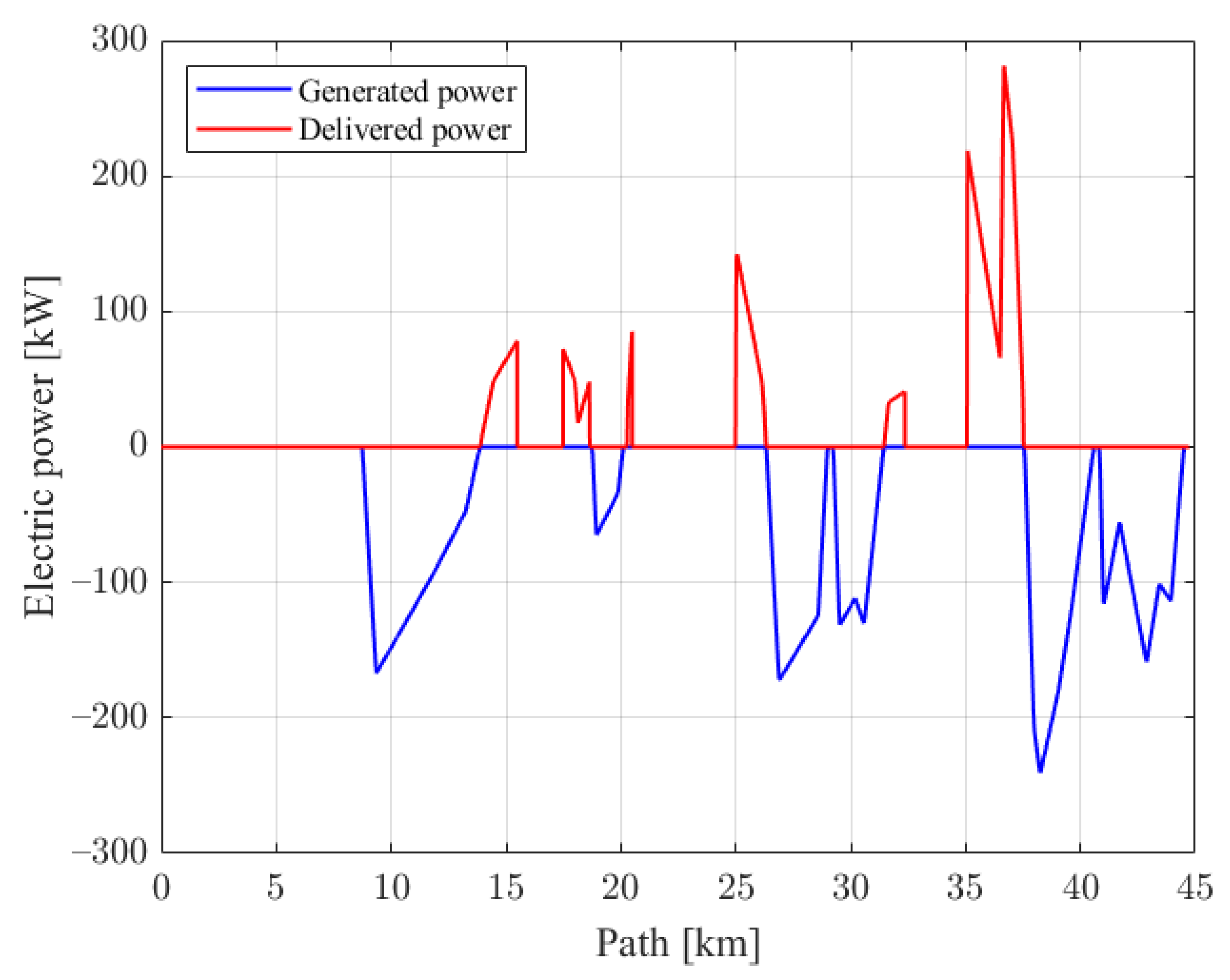
3. Results and Discussion
4. Conclusions
Author Contributions
Funding
Data Availability Statement
Acknowledgments
Conflicts of Interest
Abbreviations
| Symbols | |
| A | Mid section surface |
| Drag coefficient | |
| CO2 emission factor | |
| Thermal energy saved | |
| Electric energy used in full-electric mode | |
| f | Friction factor |
| Total resistance | |
| Tractive force | |
| Fuel saved | |
| g | Gravity acceleration |
| M | Vehicle mass in operative condition |
| Fuel flow rate | |
| Rotational speed at electric machine | |
| Number of electric machines | |
| Rotational speed at wheel | |
| Power demanded from auxiliary | |
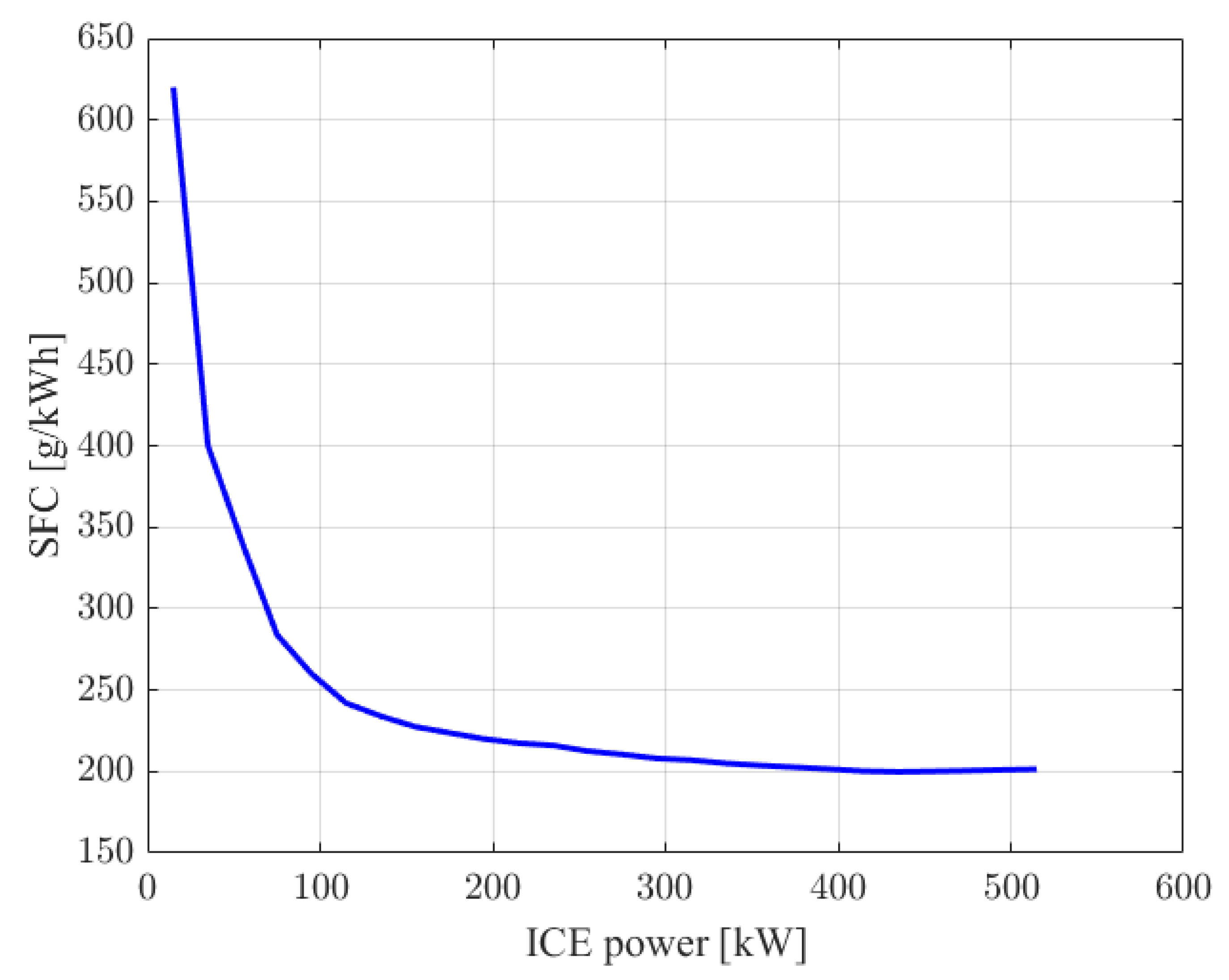
| Power required from the diesel engine | |
| r | Wheel radius |
| Air resistance | |
| Inclination resistance | |
| Rolling resistance | |
| Maximum torque that can be delivered by the electric machine | |
| Maximum torque transmitted to the wheel | |
| Demanded torque | |
| Vehicle speed | |
| Reference vehicle speed | |
| Greek symbols | |
| Path slope | |
| Inertia factor | |
| Losses due to engine accessories | |
| Electric machine transmission efficiency | |
| Hydrostatic transmission gearbox efficiency | |
| Hydrostatic transmission efficiency | |
| Air density | |
| Fuel density | |
| Electric machine transmission ratio | |
| Acronyms | |
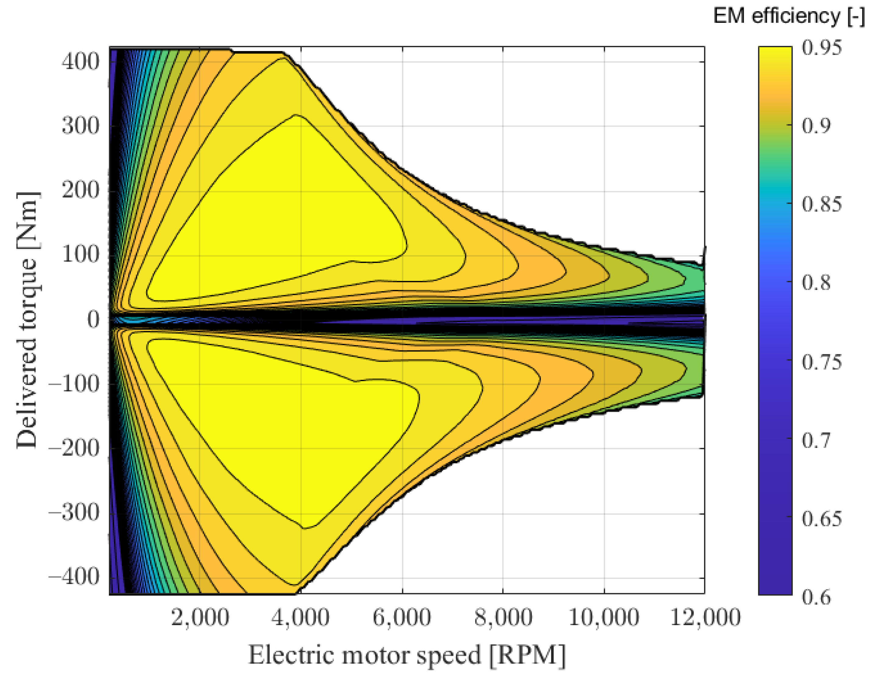
| Electric motor | |
| Energy storage system | |
| Internal combustion engine | |
| International energy agency | |
| Regenerative braking | |
| Specific fuel consumption |
References
- Transport Tracking Report—IEA, 2022. Available online: https://www.iea.org/reports/transport (accessed on 19 December 2022).
- Global CO2 Emissions from Transport by Sub-Sector in the Net Zero Scenario, 2000–2030, IEA, Paris, 2022. Available online: https://www.iea.org/data-and-statistics/charts/global-co2-emissions-from-transport-by-sub-sector-in-the-net-zero-scenario-2000-2030 (accessed on 19 December 2022).
- Rail Tracking Report-IEA, 2022. Available online: https://www.iea.org/reports/rail (accessed on 19 December 2022).
- Xu, S.; Chen, C.; Lin, Z.; Zhang, X. Introduction to Special Issue on High-Efficiency and Intelligent Train Traction System, 2022. Available online: https://academic.oup.com/tse/article/4/1/tdab028/6570917?login=false (accessed on 19 December 2022).
- Ghaviha, N.; Campillo, J.; Bohlin, M.; Dahlquist, E. Review of application of energy storage devices in railway transportation. Energy Procedia 2017, 105, 4561–4568. [Google Scholar] [CrossRef]
- International Energy Agency. Railway Handbook 2017, Energy Consumption and CO2 Emissions; International Union of Railways: Paris, France, 2017; Available online: https://www.iea.org/reports/railway-handbook-2017 (accessed on 19 December 2022).
- Italian Railway Network-RFI, 2022. Available online: https://www.rfi.it/it/rete/la-rete-oggi.html (accessed on 19 December 2022).
- Chan, C.C. The state of the art of electric and hybrid vehicles. Proc. IEEE 2002, 90, 247–275. [Google Scholar] [CrossRef] [Green Version]
- Clarke, P.; Muneer, T.; Cullinane, K. Cutting vehicle emissions with regenerative braking. Transp. Res. Part D Transp. Environ. 2010, 15, 160–167. [Google Scholar] [CrossRef]
- Schmid, S.; Ebrahimi, K.; Pezouvanis, A.; Commerell, W. Model-based comparison of hybrid propulsion systems for railway diesel multiple units. Int. J. Rail Transp. 2018, 6, 16–37. [Google Scholar] [CrossRef] [Green Version]
- González-Gil, A.; Palacin, R.; Batty, P. Sustainable urban rail systems: Strategies and technologies for optimal management of regenerative braking energy. Energy Convers. Manag. 2013, 75, 374–388. [Google Scholar] [CrossRef] [Green Version]
- Ogasa, M. Energy saving and environmental measures in railway technologies: Example with hybrid electric railway vehicles. IEEJ Trans. Electr. Electron. Eng. 2008, 3, 15–20. [Google Scholar] [CrossRef]
- Nasri, A.; Moghadam, M.F.; Mokhtari, H. Timetable optimization for maximum usage of regenerative energy of braking in electrical railway systems. In Proceedings of the SPEEDAM 2010, Pisa, Italy, 14–16 June 2010; pp. 1218–1221. [Google Scholar] [CrossRef]
- Murray-Smith, D. A Review of Developments in Electrical Battery, Fuel Cell and Energy Recovery Systems for Railway Applications: A Report for the Scottish Association for Public Transport. 2019. Available online: https://eprints.gla.ac.uk/204435/ (accessed on 19 December 2022).
- Mayrink Jr, S.; Oliveira, J.G.; Dias, B.H.; Oliveira, L.W.; Ochoa, J.S.; Rosseti, G.S. Regenerative braking for energy recovering in diesel-electric freight trains: A technical and economic evaluation. Energies 2020, 13, 963. [Google Scholar] [CrossRef] [Green Version]
- Hamada, A.T.; Orhan, M.F. An overview of regenerative braking systems. J. Energy Storage 2022, 52, 105033. [Google Scholar] [CrossRef]
- Steiner, M.; Scholten, J. Energy storage on board of railway vehicles. In Proceedings of the 2005 European Conference on Power Electronics and Applications, Dresden, Germany, 11–14 September 2005; p. 10. [Google Scholar] [CrossRef]
- Reddy, T.B. Linden’s Handbook of Batteries; McGraw-Hill Education: New York, NY, USA, 2011. [Google Scholar]
- Ceraolo, M.; Lutzemberger, G.; Meli, E.; Pugi, L.; Rindi, A.; Pancari, G. Energy storage systems to exploit regenerative braking in DC railway systems: Different approaches to improve efficiency of modern high-speed trains. J. Energy Storage 2018, 16, 269–279. [Google Scholar] [CrossRef]
- Mongird, K.; Viswanathan, V.V.; Balducci, P.J.; Alam, M.J.E.; Fotedar, V.; Koritarov, V.S.; Hadjerioua, B. Energy Storage Technology and Cost Characterization Report; Technical Report; Pacific Northwest National Lab. (PNNL): Richland, WA, USA, 2019. Available online: https://energystorage.pnnl.gov/pdf/PNNL-28866.pdf (accessed on 19 December 2022).
- Fayad, A.; Ibrahim, H.; Ilinca, A.; Sattarpanah Karganroudi, S.; Issa, M. Energy Recovering Using Regenerative Braking in Diesel–Electric Passenger Trains: Economical and Technical Analysis of Fuel Savings and GHG Emission Reductions. Energies 2021, 15, 37. [Google Scholar] [CrossRef]
- García-Garre, A.; Gabaldón, A. Analysis, evaluation and simulation of railway diesel-electric and hybrid units as distributed energy resources. Appl. Sci. 2019, 9, 3605. [Google Scholar] [CrossRef] [Green Version]
- Leska, M.; Grüning, T.; Aschemann, H.; Rauh, A. Optimization of the longitudinal dynamics of parallel hybrid railway vehicles. In Proceedings of the 2012 IEEE International Conference on Control Applications, Dubrovnik, Croatia, 3–5 October 2012; pp. 202–207. [Google Scholar] [CrossRef]
- Tomasikova, M.; Tropp, M.; Gajdosik, T.; Krzywonos, L.; Brumercik, F. Analysis of transport mechatronic system properties. Procedia Eng. 2017, 192, 881–886. [Google Scholar] [CrossRef]
- Hillmansen, S.; Roberts, C. Energy storage devices in hybrid railway vehicles: A kinematic analysis. Proc. Inst. Mech. Eng. Part F J. Rail Rapid Transit. 2007, 221, 135–143. [Google Scholar] [CrossRef]
- Ogawa, T.; Yoshihara, H.; Wakao, S.; Kondo, K.; Kondo, M. Energy consumption analysis of FC-EDLC hybrid railway vehicle by dynamic programming. In Proceedings of the 2007 European Conference on Power Electronics and Applications, Aalborg, Denmark, 2–5 September 2007; pp. 1–8. [Google Scholar] [CrossRef]
- Ciccarelli, F.; Iannuzzi, D.; Tricoli, P. Control of metro-trains equipped with onboard supercapacitors for energy saving and reduction of power peak demand. Transp. Res. Part C Emerg. Technol. 2012, 24, 36–49. [Google Scholar] [CrossRef]
- Sumpavakup, C.; Ratniyomchai, T.; Kulworawanichpong, T. Optimal energy saving in DC railway system with on-board energy storage system by using peak demand cutting strategy. J. Mod. Transp. 2017, 25, 223–235. [Google Scholar] [CrossRef] [Green Version]
- Frilli, A.; Meli, E.; Nocciolini, D.; Pugi, L.; Rindi, A. Energetic optimization of regenerative braking for high speed railway systems. Energy Convers. Manag. 2016, 129, 200–215. [Google Scholar] [CrossRef]
- Stagni, E. Meccanica della Locomozione; Patron: Bologna, Italy, 1980. [Google Scholar]
- Carpignano, A. Meccanica dei Trasporti Ferroviari e Tecnica Della Locomozione; Levrotto & Bella: Turin, Italy, 1985. [Google Scholar]
- Shimada, M.; Miyaji, Y.; Kaneko, T.; Suzuki, K. Energy-saving technology for railway traction systems using onboard storage batteries. Hitachi Rev. 2012, 61, 312–318. [Google Scholar]
- Jufri, F.H.; Aryani, D.R.; Garniwa, I.; Sudiarto, B. Optimal battery energy storage dispatch strategy for small-scale isolated hybrid renewable energy system with different load profile patterns. Energies 2021, 14, 3139. [Google Scholar] [CrossRef]
- Jakhrani, A.Q.; Rigit, A.R.H.; Othman, A.K.; Samo, S.R.; Kamboh, S.A. Estimation of carbon footprints from diesel generator emissions. In Proceedings of the 2012 International Conference on Green and Ubiquitous Technology, Bandung, Indonesia, 7–8 July 2012; pp. 78–81. [Google Scholar] [CrossRef]


| TUNNEL | NO TUNNEL | ||
|---|---|---|---|
| > 0 | < 0 | > 0 | < 0 |
| Full-electric | Regenerative braking | Diesel propulsion | Regenerative braking |
| Parameter | Value |
|---|---|
| M | 71.3 t |
| 52.3 kW | |
| A | 9 m2 |
| 0.9 | |
| g | 9.807 m/s2 |
| r | 0.475 m |
| 0.1 | |
| f | 0.003 |
| 0.95 | |
| 0.95 | |
| 21.089 | |
| 0.95 |
| Benefit | Value |
|---|---|
| Thermal energy saved | 29.13 kWh |
| Electric energy for traction | 13.5 kWh |
| Electric energy recovered | 36.75 kWh |
| Net battery energy balance | 23.25 kWh |
| Fuel saving | 20 % |
| CO2 avoided emissions | 22.3 kg |
Disclaimer/Publisher’s Note: The statements, opinions and data contained in all publications are solely those of the individual author(s) and contributor(s) and not of MDPI and/or the editor(s). MDPI and/or the editor(s) disclaim responsibility for any injury to people or property resulting from any ideas, methods, instructions or products referred to in the content. |
© 2023 by the authors. Licensee MDPI, Basel, Switzerland. This article is an open access article distributed under the terms and conditions of the Creative Commons Attribution (CC BY) license (https://creativecommons.org/licenses/by/4.0/).
Share and Cite
Cutrignelli, F.; Saponaro, G.; Stefanizzi, M.; Torresi, M.; Camporeale, S.M. Study of the Effects of Regenerative Braking System on a Hybrid Diagnostic Train. Energies 2023, 16, 874. https://doi.org/10.3390/en16020874
Cutrignelli F, Saponaro G, Stefanizzi M, Torresi M, Camporeale SM. Study of the Effects of Regenerative Braking System on a Hybrid Diagnostic Train. Energies. 2023; 16(2):874. https://doi.org/10.3390/en16020874
Chicago/Turabian StyleCutrignelli, Francesco, Gianmarco Saponaro, Michele Stefanizzi, Marco Torresi, and Sergio Mario Camporeale. 2023. "Study of the Effects of Regenerative Braking System on a Hybrid Diagnostic Train" Energies 16, no. 2: 874. https://doi.org/10.3390/en16020874