Article

Frequency Regulation of Electric Vehicle Aggregator Considering User Requirements with Limited Data Collection

1
College of Energy and Electrical Engineering, Hohai University, Nanjing 211100, China
2
Electric Power Research Institute, State Grid Jiangsu Electric Power Co., Ltd., Nanjing 211103, China
*
Authors to whom correspondence should be addressed.
Energies 2023, 16(2), 848; https://doi.org/10.3390/en16020848
Submission received: 28 November 2022 / Revised: 6 January 2023 / Accepted: 9 January 2023 / Published: 11 January 2023
(This article belongs to the Special Issue Research on Energy Storage and Conversion Management)

Abstract

:
High penetration of renewable energy in the power grid causes serious frequency deviations. Large-scale integrations of electric vehicles (EVs) in the power grid provide considerable vehicle-to-grid potential for frequency regulation. Existing frequency regulation strategies with aggregated EVs realize accurate power control that relies on complete information interaction between the EV aggregator and individual EVs. However, the data collection for all EV parameters is not applicable due to privacy protection and the limited communication environment. Considering the limited data collection from grid-connected EVs, this paper provides a novel frequency regulation strategy and tends to address the uncertain influence from EV users’ charging requirements, the EV aggregator’s power regulation, and the frequency regulation performance. Firstly, considering the influence of the limited data collection by EVs on the users’ requirement of traveling and regulation preference, a probabilistic evaluation model for the available regulation capacity of the EV aggregator and the probabilistic control method for EVs are developed. Then, a frequency regulation strategy with error correction control and progressive regulation recovery is developed to simultaneously guarantee the system frequency regulation performance and the regulation requirements of EV users. Finally, case studies are carried out to validate the effectiveness of frequency regulation strategy for decreasing the uncertain influence from the limited data collection, ensuring the EV users’ requirements, and improving the system frequency stability.

1. Introduction

In recent years, with the high penetration of wind and solar renewable energy in the power grid and the power fluctuation caused by the strong randomness and intermittence of renewable energy has aroused considerable attention [1]. Owing to the responding time delay and the insufficient ramp rate, conventional generation has difficulty following the rapid power variation in renewable energy, and the incurred instability issue of system frequency cannot be ignored any longer [2,3]. Energy storage with rapid responding speed is an alternative for improving the frequency stability, but its wide application is not economical and lacks the technical rigor.
With the developing trend of low-carbon transportation, the use of electric vehicles (EVs) is growing fast worldwide due to low carbon emissions. By 2021, the global EVs increased to 16.5 million, triple the number in 2018 [4]. In 2021, nearly 10% of global vehicles sales were EVs, and the sales of EVs doubled from the previous year to a new record of 6.6 million. The kinetic energy of an EV on roads is provided by the battery. After travel, the EV requires connection to the power system for energy acquisition. The integration of so many EVs aggravates the peak–valley difference in the load and imposes enormous pressure on the stable operation of the power system [5].
For an EV, the connecting period at the parking slot is usually much longer than the required charging period [6]. During the connecting period, an EV can schedule the charging period, and even discharge to support the operation of the power grid [7]. With the development of modern communication technology, the geographically dispersed EVs in the power grid can be regarded as an EV aggregator [8]. The EV aggregator manages a population of EVs in a centralized system [8,9]. The centralized system employs a control center to collect the information from all available EVs and controls when and at what rate each EV will charge or discharge [10,11]. Although the regulation capacity of an individual EV is small, large-scale aggregated EVs provide considerable regulation capacity and rapid responding speed for regulating the power system frequency [12].
EV aggregator modeling is the basis for utilizing the regulation capacity of centralized EVs. Review of existing literature has been conducted to investigate the regulation characteristics of the EV aggregator. Considering the temporal distribution of grid connections of EVs after travel is finished, the evaluation model for the available capacity of the EV aggregator was developed by scheduling the charging and discharging processes [5,13]. Considering that the traveling EV is affected by the traveling habit, energy requirement, and traveling purpose, the estimation method for regulation capacity of the EV aggregator was proposed by analyzing the temporal–spatial correlations of the grid connections [14,15]. Considering the additional battery degradation cost and the monetary compensation for EVs during the regulation process, the estimation for the regulation capacity of the EV aggregator is realized to improve the participation rate for power regulation [16,17]. Existing studies for modeling EV aggregators considered the traveling requirement, energy usage, and the regulation cost. However, the preferences of EV users for different regulation mode at the up- and down-directions were ignored, and the modeling methods assumed that the EV aggregator was able to acquire and record all data of charging terminals and EVs. In actual application, the EV data may be not available due to the privacy protection and the limited communication environment at present. It is essential to develop the EV aggregator model by collecting limited data as well as ensuring the EV user’s requirements.
The frequency regulation tends to guarantee the power balance between generation and load in real time [18]. A number of studies have been conducted to realize frequency regulation with an EV aggregator. The EV aggregator was regarded as a virtual power plant to regulate its total power output in the power system. During the frequency regulation, the control center of the EV aggregator should guarantee both the system-level and vehicle-level requirements with different regulation purposes. In the literature [19,20,21,22], the EV aggregator responded to the frequency variation by improving the system frequency regulation performance [19], ensuring the traveling demands of the EV users [20], decreasing the additional battery degradations of EVs [21], and improving the regulation income of EV users [22]. Once the required power dispatch of the EV aggregator for frequency regulation is determined, the control center needs to allocate the required power dispatch to individual EVs. Existing studies were conducted to coordinate the power outputs of individual EVs with different methods. In the literature [18,23,24,25], the state-of-charge (SOC) sorting method [23], the least-laxity-first method [18], the optimal control method [24], and the proportional-integral (PI) control method [25] were used to regulate the real-time power control for individual EVs. These existing methods for regulating individual EVs are based on the assumption that the acquisition of real-time state measurement for the terminal EVs and the accurate power control for terminal EVs, such as the direct control for individual EVs [18,23,24,25], have been realized in actual application. However, the limited data collection, especially the data deficiency of EV states, adds difficulty to simultaneously realizing the frequency regulation performance and the EV regulation requirement. Additionally, once the original charging state of an EV is disturbed by the frequency regulation, the EV will stay in a state of control without active state recovery. It is necessary to develop a frequency regulation strategy for the EV aggregator to ensure the traveling requirements without acquiring the data of real-time EV states.
To solve these issues, the following aspects are considered as the motivation for this paper.
(1)
The limited data collection causes the data deficiency in the EV user’s requirements for traveling and regulation preference. This data deficiency adds the difficulty to featuring the regulation characteristic of aggregated EVs. A probabilistic evaluation model of an EV aggregator is developed to evaluate the available regulation capacity under different regulation modes with the limited data acquisition of EVs.
(2)
The limited data collection incurs an uncertain power regulation in the EV aggregator and directly affects the regulation accuracy for the system frequency. A frequency regulation with the EV aggregator is developed with probabilistic control and error correction to improve the frequency regulation performance.
(3)
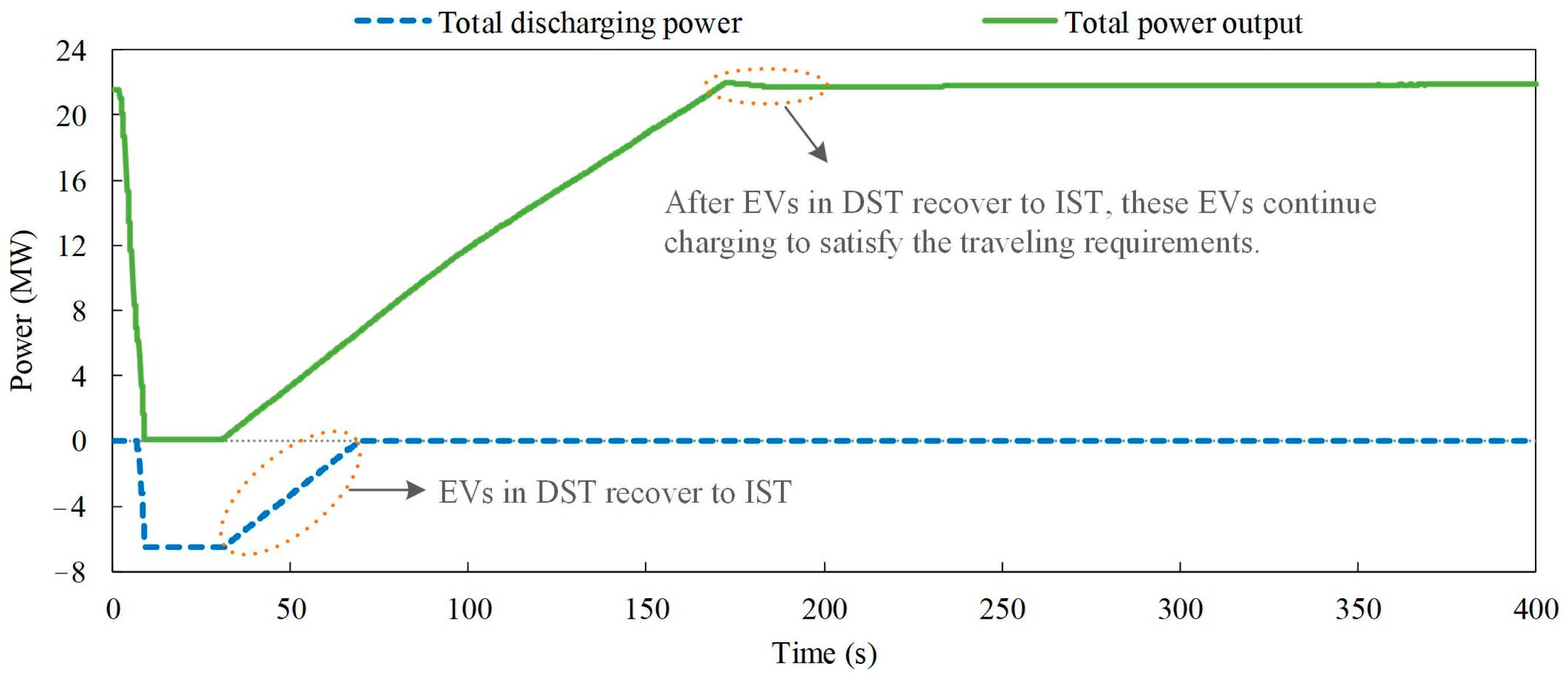
The frequency regulation with the EV aggregator affects the original charging schedules and the preferred charging requirements of EVs. Progressive regulation recovery is proposed to ensure regulation requirements of EVs during frequency regulation. The influence on charging preferences for EVs is reduced by coordinating the EV aggregator with conventional generation.
The rest of this paper is organized as follows. Section 2 introduces the regulation characteristics of the EV aggregator by discussing the regulation requirements of EV users under the limited data collection. Section 3 proposes the frequency regulation strategy with regulation error estimation and regulation recovery of the EV aggregator. Section 4 presents the simulation results. Some remarkable conclusions are summarized in Section 5.

2. Modeling for Regulation Characteristics of the EV Aggregator

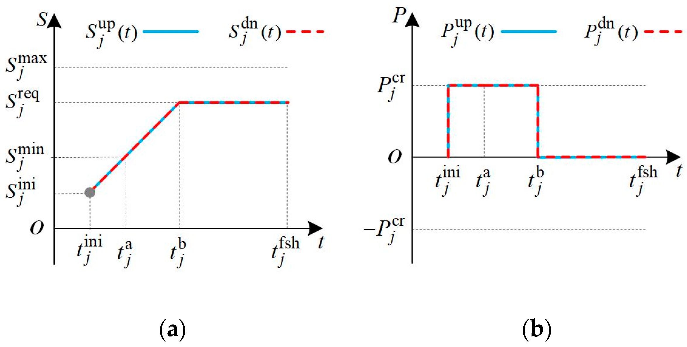
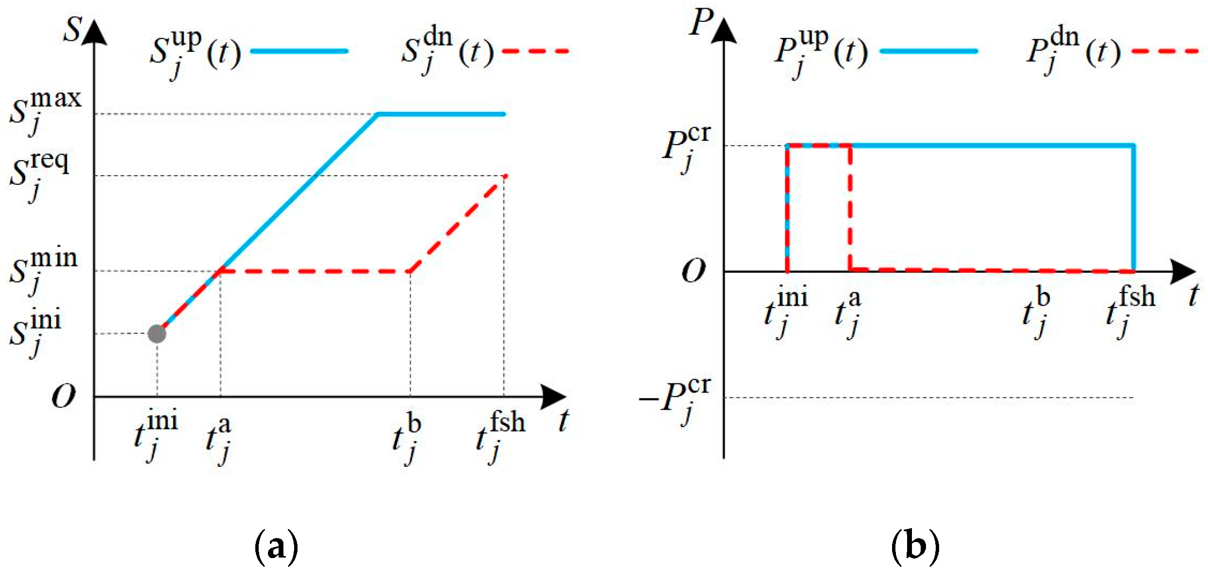
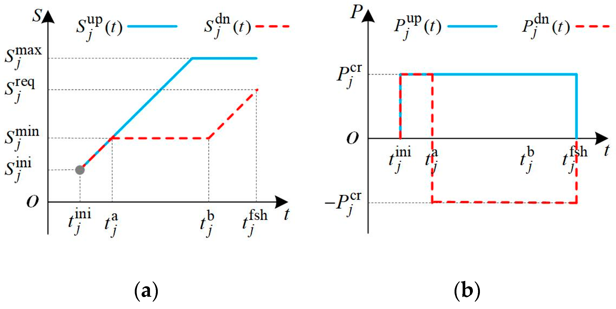
2.1. Regulation Characteristics of an EV

When an EV finishes traveling, the EV requires connection to the power grid for energy acquisition via an EV charger. Based on the exchanged power of the EV charger, the connecting state of the EV charger is divided into the charging state (CST), idle state (IST), discharging state (DST), and unused state (UST). The variable that indicates the connecting state is defined by θ j ( t ) , as given in Equation (1).
θ j ( t ) = 1 ,   C S T 0 ,   I S T 1 ,   D S T N a N ,   U S T
where j is the index of EV chargers; θ j ( t ) represents the connecting state of the j-th EV charger; and NaN means that there is no EV connection at the EV charger.
The relationship between the connecting state and the power output of an EV charger is given by Equation (2).
P j ( t ) = P j cr ;   θ j ( t ) = 1 0 ;   θ j ( t ) = 0   or   θ j ( t ) = N a N P j dr ;   θ j ( t ) = 1
where t is the current time instant; P j ( t ) is the real-time power output of the j-th EV charger; P j cr and P j dr are, respectively, the rated charging and discharging power; and P j ( t ) is the real-time exchanged power at the j-th EV charger.
The SOC is an indicator of the remaining battery energy. The variation in SOC during the connecting period is given by Equation (3).
S j ( t ) = S j ( t Δ t ) + P j ( t ) η j cr / Q j Δ t ;   θ j ( t ) = 1 S j ( t Δ t ) ;   θ j ( t ) = 0   S j ( t Δ t ) + P j ( t ) / η j dr / Q j Δ t ;   θ j ( t ) = 1
where S j ( t ) is the real-time SOC of the EV at the j-th EV charger; Q j is the battery capacity; η j cr and η j dr are, respectively, the charging and discharging efficiency; and Δ t is the time interval.
Based on the connecting state of the EV charger, four frequency regulation modes are defined by Equation (4).
Δ P j c 2 i = P j cr ;   from   CST   to   IST Δ P j i 2 d = P j dr ;   from   IST   to   DST Δ P j d 2 i = P j dr ;   from   DST   to   IST Δ P j i 2 c = P j cr ;   from   IST   to   CST
where Δ P j c 2 i , Δ P j i 2 d , Δ P j d 2 i , and Δ P j i 2 c are, respectively, the available regulation capacity from CST to IST (C2I), from IST to DST (I2D), from DST to IST (D2I), and from IST to CST (I2C). The regulation modes from CST to DST and from DST to CST are not defined because the regulation costs caused by scheduled charging and discharging differ.
However, the realization of four regulation modes affects the EV battery lifetime [26,27]. As reported in the literature [28,29], the factors affecting battery lifespan are discussed, and these factors include ambient temperature, charging/discharging rate, operating SOC, depth of discharge (DOD), and cycle number. The lithium-ion battery, which is widely applied in EVs, is taken as the example to introduce the influence of regulation modes on battery lifetime.
The frequency regulation concentrates on the EV chargers in communities and public parking areas that have a low charging rate. These parking EVs have preference for power regulation as their parking time period is usually much longer than their own charging period. At the low charging/discharging rate, the effect on battery lifetime from the ambient temperature and the charging/discharging rate is negligible [30]. Relevant studies reveal that the effect is not generally the same for different operating SOC values [29]. Compared with DOD, the effect from different operating SOC can also be neglected [31]. Thus, the main factors that affect the battery lifetime are the DOD and the cycle number. As the battery cycle number under a specified DOD is provided by the manufacturer, the total processed energy Epro in the battery lifetime can be calculated. Cbat is defined as the battery purchase cost. For the switch among the four regulation modes, the battery-wear cost Cwer is directly determined by the discharged energy Edis, i.e., Cwer = 2CbatEdis/Epro [31]. With the rapid development in battery technology in recent years, the battery purchase cost is decreasing and the battery cycle number is increasing [32]. As reported in the literature [28,29,30,31,32,33], the battery cycle number varies from 4000 to 1,000,000. It is believed that the battery-wear cost of EVs caused by switching between the four regulation modes will continue to decrease in the future, and EV users will have a stronger preference for providing regulation service.
As concluded above, the extra battery-wear cost caused by switching between the four regulation modes is approximately proportional to the discharged energy. Thus, in this paper, it is assumed that EV users tend to contract with the operator of the EV aggregator at a certain compensation price per unit of discharged energy. It is also assumed that the EV aggregator has the authority to implement the four regulation modes for frequency regulation with the contracted EVs. However, owing to the different preferences of EV users, the penetration level of EVs for demand response is greater when the compensation price is higher [34]. Under different penetration levels of EVs, relevant studies will be conducted to reflect the different preferences of EV users. This paper focus more attention on modeling the aggregated EVs for frequency regulation, and the compensation price is not discussed in detail.
Therefore, the control parameter δ j ( t ) is defined by Equation (5) to describe the control action for the connecting state variation for each EV during the frequency regulation process.
δ j ( t ) = 1 ;   I 2 C 0 ;   Without   CNT   control 1 ;   C 2 I / I 2 D 2 ;   C 2 I   &   I 2 D
where δ j ( t ) = 0 indicates there is no control for the connecting state; δ j ( t ) = 1 indicates the EV in IST is controlled to CST; δ j ( t ) = 1 indicates the EV is controlled from CST to IST or from IST to DST; and δ j ( t ) = 2 indicates the EV is controlled from CST to IST and then is further controlled from IST to DST.

2.2. Regulation Requirements of the EV User

(1)
Requirement for traveling
The energy acquisition by connecting to the power grid is used to ensure the future traveling requirement. To describe the charging anxiety for traveling in an EV, the charging laxity T j lax ( t ) is defined by Equation (6) to describe the maximum time duration with IST during the connection period.
T j lax ( t ) = ( t j fsh t ) ( S j req S j ( t ) ) Q j P j cr η j cr
where S j req is the required SOC for traveling and t j fsh is the time when the EV leaves the power grid.
When T j lax ( t ) > 0 , a greater T j lax ( t ) means the EV has more time to remain IST. T j lax ( t ) 0 means the EV has to enter into the forced CST. As given by Equation (7), π j ( t ) is a binary variable that indicates whether or not the EV has entered into the forced CST.
π j ( t ) = 1 ,   T j lax ( t ) > 0 0 ,   T j lax ( t ) 0
(2)
Requirement for regulation preference
Considering the regulation preference of EV users, three regulation modes are defined: ① EV does not participate in frequency regulation; ② EV participates in frequency regulation with C2I or I2C; and ③ EV participates in the four regulation modes in Equation (4). Then, considering the regulation preference, Equation (4) is recast by Equation (8) to describe the available regulation capacity of an EV with four regulation modes under different regulation preferences.
Δ P j c 2 i = P j cr δ j c δ j d ;   C 2 I Δ P j i 2 d = P j dr δ j c δ j d ;   I 2 D Δ P j d 2 i = P j dr δ j c δ j d ;   D 2 I Δ P j i 2 c = P j cr δ j c δ j d ;   I 2 C
where δ j c and δ j d are binary variables; δ j c represents whether or not the EV participates in C2I or I2C; and δ j d represents whether or not the EV participates in I2D or D2I.
(3)
Regulation capacity of an EV under different requirements
Considering the regulation requirements of the EV user, the regulation capacity of an EV under different regulation modes is shown in Figure 1, Figure 2 and Figure 3. The connecting time instant with the power grid is t j ini ; S j min and S j max are, respectively, the minimum and maximum SOC values for regulation. S j ini is the initial SOC value at t j ini . S j up ( t ) and S j dn ( t ) are, respectively, defined as the upper and lower boundaries of the EV’s SOC variation range during the connecting period with the power grid. P j up ( t ) and P j dn ( t ) are, respectively, defined as the upper and lower boundaries of the EV’s power regulation range during the connecting period.
As shown in Figure 1, the power limitations under regulation mode 1 are given by Equation (9). As shown in Figure 2, the power regulation under regulation mode 2 is realized by switching between CST and IST, and is limited by the real-time SOC, as given by Equations (11) and (12). As shown in Figure 3, the power regulation under regulation mode 3 is realized by switching between CST and IST and between IST and DST, and is limited by the real-time SOC, as given by Equations (14) and (15).
P j up ( t ) = P j dn ( t ) = 0 ;   t < t j ini   or   t > t j b P j cr ;   t j ini t t j b
where δ j c = δ j d = 0 , S j up ( t ) = S j dn ( t ) and t j b is further given by Equation (10).
t j b = t j ini + S j req S j ini P j cr η j cr Q j
P j up ( t ) = 0 ;   t < t j ini   or   t > t j fsh P j cr sign ( S j max ( t ) S j ( t ) ) ;   t j ini t t j fsh
P j dn ( t ) = 0 ;   t < t j ini   or   t t j a P j cr ;   t j ini t < t j a
where δ j c = 1 , δ j d = 0 , and t j a is further given by Equation (13).
t j a = max ( t j ini , t j ini + S j min S j ini P j cr η j cr Q j )
P j up ( t ) = 0 ;   t < t j ini   or   t > t j fsh P j cr sign ( S j max ( t ) S j ( t ) ) ;   t j ini t t j fsh
P j dn ( t ) = 0 ;   t < t j ini   or   t > t j fsh P j cr ;   t j ini t < t j a P j dr sign ( S j ( t ) S j min ( t ) ) ;   t j a t t j fsh
where δ j c = 1 and δ j d = 1 .

2.3. Regulation Capacity of EVs with Limited Data Collection

The operator of the EV aggregator manages individual EVs on a large-scale. Existing literature assumed the operator could collect all parameters about each EV and each EV charger. However, the data for EV parameters about traveling, preference, and charging are usually not available in actual application due to privacy protection or limited communication. It may be similar to mobile phones; EV users should have the authority to determine whether or not to upload their EV data.
It is assumed that the EV parameters defined by Equation (16) can be only measured and stored by the terminal device and are not available to the operator of the EV aggregator. The operation parameters of the EV charger defined by Equation (17) are measured by the operator of the EV aggregator. Thus, the privacy of EV users is protected.
Φ con = t j ini , t j fsh , S j ini , S j req , S j min , S j max , δ j c , δ j d , S j ( t ) , Q j , P j cr , P j dr , η j cr , η j dr
Φ up = j , t j cnt , θ j ( t ) , P j ( t ) , δ j ( t )
where t j cnt is the time instant for grid connection of the EV at the j-th EV.
The charging terminal is the intelligent EV charger. On the one hand, each EV charger receives the control signal for the exchanged power between the EV and the power grid. On the other hand, the EV charger must ensure enough energy acquisition for traveling by applying the operation constraints shown in Figure 1, Figure 2 and Figure 3. Thus, the EV charger may refuse to respond to the control signal from the EV aggregator in some extreme conditions, such as when the EV user is anxious to leave.
(1)
Regulation capacity evaluation of the EV aggregator with limited data
Based on the limited data acquisition of the EV aggregator, the numbers of EVs with different connecting states can be achieved with Equation (18). The numbers of EVs with different control actions are given by Equation (19).
N cst ( t ) = | | Ω cst ( t ) | | 0 ;   Ω cst ( t ) = { j | θ j ( t ) = 1 } N ist ( t ) = | | Ω ist ( t ) | | 0 ;   Ω ist ( t ) = { j | θ j ( t ) = 0 } N dst ( t ) = | | Ω dst ( t ) | | 0 ;   Ω dst ( t ) = { j | θ j ( t ) = 1 } N ust ( t ) = | | Ω ust ( t ) | | 0 ;   Ω ust ( t ) = { j | θ j ( t ) = N a N }
where N cst ( t ) , N ist ( t ) , N dst ( t ) , and N ust ( t ) are, respectively, the numbers of EVs in CST, IST, DST, and UST; and Ω cst ( t ) , Ω ist ( t ) , Ω dst ( t ) , and Ω ust ( t ) are, respectively, the sets of indices of EVs in CST, IST, DST, and UST.
N i 2 c ( t ) = | | Ω i 2 c ( t ) | | 0 ;   Ω i 2 c ( t ) = { j | δ j ( t ) = 1 } N c 2 i ( t ) = | | Ω c 2 i ( t ) | | 0 ;   Ω c 2 i ( t ) = { j | θ j ( t ) = 0   &   δ j ( t ) = 1 } N i 2 d ( t ) = | | Ω i 2 d ( t ) | | 0 ;   Ω i 2 d ( t ) = { j | θ j ( t ) = 1   &   δ j ( t ) = 1 } N c 2 d ( t ) = | | Ω c 2 d ( t ) | | 0 ;   Ω c 2 d ( t ) = { j | θ j ( t ) = 2 }
where Ω i 2 c ( t ) , Ω c 2 i ( t ) , Ω i 2 d ( t ) , and Ω c 2 d ( t ) are, respectively, the sets of indices of EVs that are controlled from IST to CST, from CST to IST, from IST to DST, and from CST to DST; and N i 2 c ( t ) , N c 2 i ( t ) , N i 2 d ( t ) , and N c 2 d ( t ) are, respectively, the numbers of EVs in Ω i 2 c ( t ) , Ω c 2 i ( t ) , Ω i 2 d ( t ) , and Ω c 2 d ( t ) .
The operator of the EV aggregator manages a large number of grid-connected EVs with dispersed distribution. The power output of the EV aggregator, which is defined as P A ( t ) , is achieved with Equation (20) by aggregating the exchanged power of all available EVs with EV chargers.
P A ( t ) = j j Ω ( t ) P j ( t )
where Ω ( t ) = { Ω cst ( t ) , Ω ist ( t ) , Ω dst ( t ) , Ω ust ( t ) } .
The power output of the EV aggregator can be controlled to regulate up and down under the four regulation modes. The available regulation capacity of the EV aggregator in the up-direction with D2I is given by Equation (21). The available regulation capacity of the EV aggregator in the up-direction with D2I and I2C is given by Equation (22).
P A d 2 i , up ( t ) = P A ( t ) + N dst ( t ) P ¯ dr
where P ¯ dr is the average value of discharging power for all grid-connected EVs.
P A d 2 c , up ( t ) = ( N cst ( t ) + N ist ( t ) + N dst ( t ) ) P ¯ cr ( N ist ( t ) N c 2 i ( t ) + N i 2 d ( t ) ) ( 1 φ c φ d ) P ¯ cr
where φ c is the proportion of EVs for only participating C2I and I2C; φ d is the proportion of EVs for participating in all four regulation modes; P ¯ cr is the average value of charging power for all grid-connected EVs; the first item assumes all connected EVs enter into CST; and the second item describes the CST EVs that do not participate in frequency regulation.
The available regulation capacity of the EV aggregator in the down-direction with C2I is given by Equation (23). The available regulation capacity of the EV aggregator in the down-direction with C2I and I2D is given by Equation (24).
P A c 2 i , dn ( t ) = N dst ( t ) P ¯ dr + ( N cst ( t ) + N c 2 i ( t ) N i 2 c ( t ) N i 2 d ( t ) ) ( 1 φ c φ d ) P ¯ cr
where the first item describes the total power of all DST EVs and the second item describes the CST EVs that do not participate in frequency regulation.
P A c 2 d , dn ( t ) = ( N cst ( t ) + N c 2 i ( t ) N i 2 c ( t ) N i 2 d ( t ) ) ( 1 φ c φ d ) P ¯ cr ( N cst ( t ) + N c 2 i ( t ) N i 2 c ( t ) N i 2 d ( t ) ) φ d P ¯ dr ( N ist ( t ) N c 2 i ( t ) + N i 2 d ( t ) ) φ d P ¯ dr
where the first item describes the CST EVs that do not participate in frequency regulation; the second item selects the controllable CST EVs for discharging; and the third item selects the controllable IST EVs for discharging.
(2)
Regulation requirement insurance for individual EVs at the charging terminal
Owing to the limited data collected by the EV aggregator, the deterministic control of each EV may affect the requirement for traveling and regulation preference, and is not applicable in reality. Thus, the probabilistic control signal [u(t), v(t)] is developed to ensure the requirement for both traveling and regulation preference. Both u(t) and v(t) varies within [−1, 1]. When 1 u ( t ) < 0 and 1 v ( t ) < 0 , the EV aggregator expects the EVs in CST to switch to IST with the proportion of u ( t ) , and then expects the EVs in IST to switch to DST with the proportion of v ( t ) . When 0 u ( t ) 1 and 0 v ( t ) 1 , the EV aggregator expects the EVs in DST to switch to IST with the proportion of v ( t ) , and then expects the EVs in IST to switch to CST with the proportion of u ( t ) . This section introduces the meaning of the control signal [u(t), v(t)]; how to achieve [u(t), v(t)] is described in the frequency regulation.
The EV aggregator broadcasts [u(t), v(t)] to all available grid-connected EVs. After receiving the control signal, an EV determines whether or not to conduct the target control action based on the signal values, the EV’s connecting state, and the EV’s actual requirements for traveling and regulation preference. The control action of an individual EV is shown below:
(1) When 1 u ( t ) < 0 and 1 v ( t ) < 0 , the control action tends to decrease the exchanged power of the EV. If the EV is in CST (i.e., θ j ( t ) = 1 ), whether or not the EV conducts the control action is determined by the probabilistic process given in Equation (25). If the EV is in IST (i.e., θ j ( t ) = 0 or θ j ( t ) + Δ θ j ( t ) = 0 ), the control action is determined by Equation (26).
Δ θ j ( t ) = δ j c π j ( t ) u ( t ) | u ( t ) | ,   ϖ j ( t ) | u ( t ) | 0 ,   ϖ j ( t ) > | u ( t ) |
where Δ θ j ( t ) indicates the variation in θ j ( t ) under the control signal and ϖ j ( t ) is a probability value generated at the user side and satisfies the uniform distribution U(0, 1).
Δ θ j ( t ) = δ j d π j ( t ) v ( t ) | v ( t ) | ,   ϖ j ( t ) | v ( t ) | 0 ,   ϖ j ( t ) > | v ( t ) |
(2) When 0 u ( t ) 1 and 0 v ( t ) 1 , the control action tends to increase the exchanged power of the EV. If the EV is in DST (i.e., θ j ( t ) = 1 ), the control action is determined by Equation (27). If the EV is in IST (i.e., θ j ( t ) = 0 or θ j ( t ) + Δ θ j ( t ) = 0 ), the control action is determined by Equation (28).
Δ θ j ( t ) = δ j d π j ( t ) ,   ϖ j ( t ) | v ( t ) | 0 ,   ϖ j ( t ) > | v ( t ) |
Δ θ j ( t ) = δ j c π j ( t ) ,   ϖ j ( t ) | u ( t ) | 0 ,   ϖ j ( t ) > | u ( t ) |
In actual application, the EV aggregator determines the control signal based on the required power regulation. The individual grid-connected EVs respond to the control signal considering the requirements for traveling and regulation preference. The EV charger has the limited control authority to guarantee the different requirements of EV users.

3. Frequency Regulation Strategy with the EV Aggregator

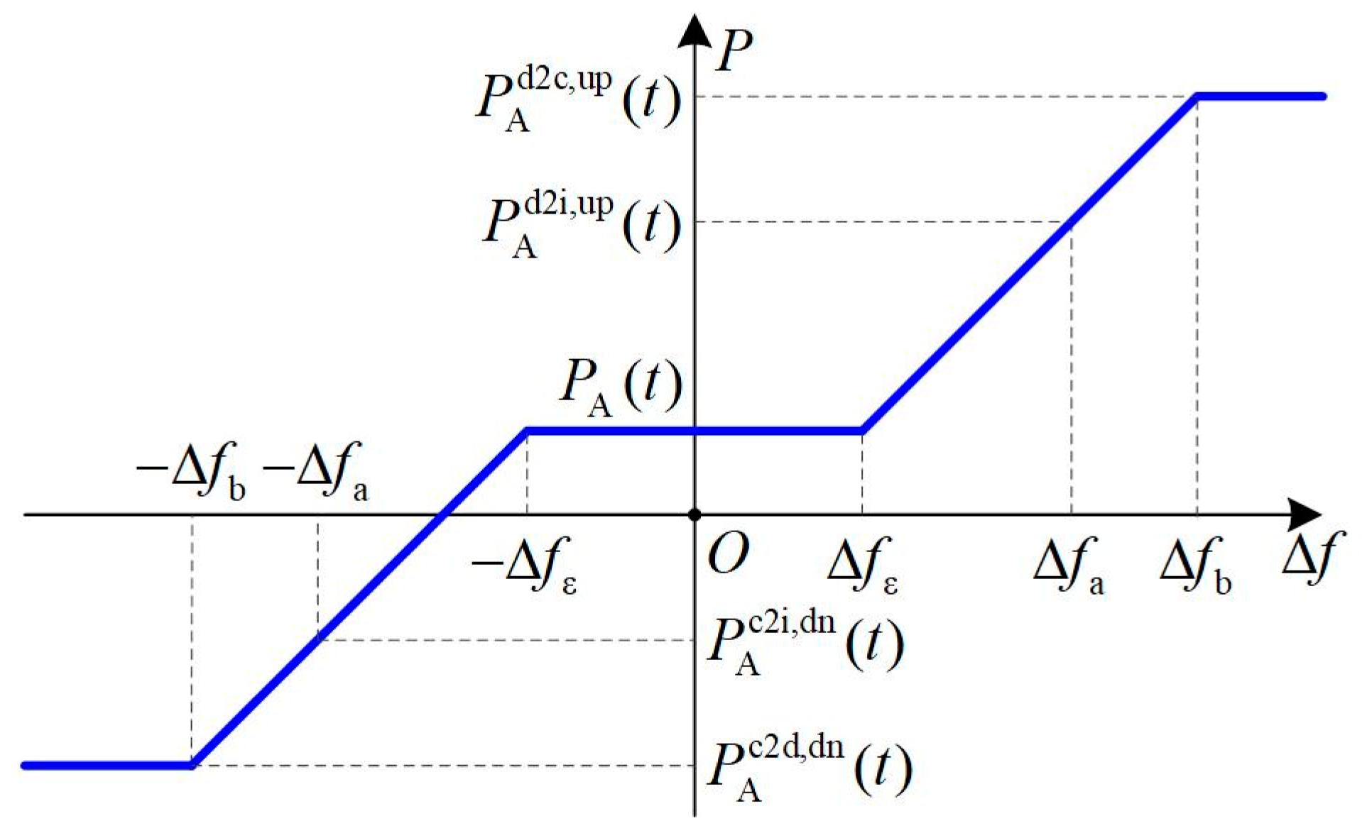
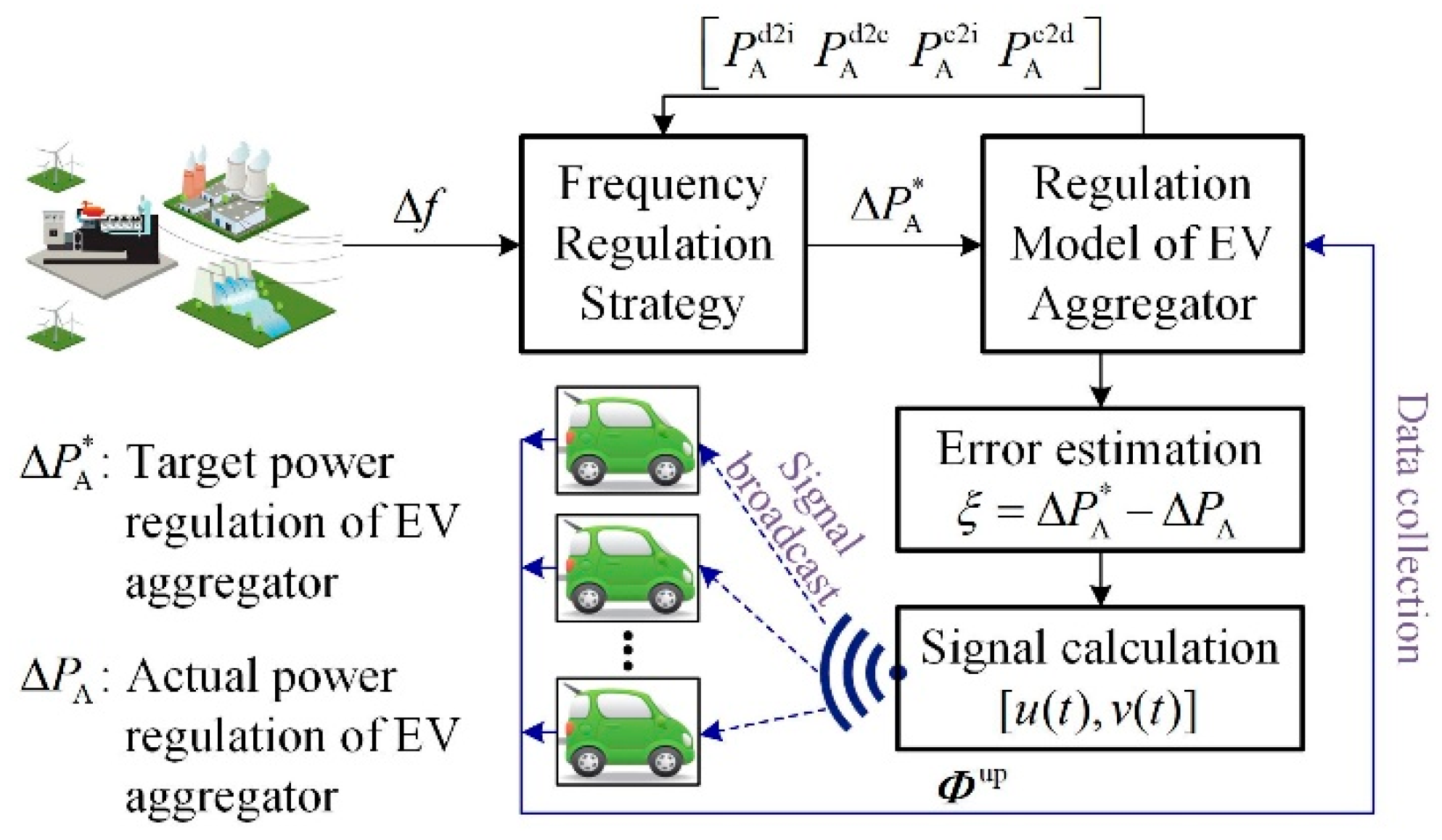
3.1. Frequency Regulation Characteristics of the EV Aggregator

When participating in frequency regulation, the EV aggregator provides the regulation service by managing the large-scale, geographically dispersed EV batteries. The frequency regulation characteristics of the EV aggregator at a specific time instant are shown in Figure 4; [ Δ f ε , Δ f ε ] is the allowable variation range in the system frequency. When the frequency deviation Δ f ( t ) is greater than Δ f ε , the EV aggregator tends to broadcast the control signal to decrease the power output of the aggregated EVs. With increasing Δ f ( t ) , the power decrease is realized with D2I control, and then the I2C control is applied if the regulation capacity from D2I is insufficient. When the frequency deviation Δ f ( t ) is less than Δ f ε , the power increase in the EV aggregator is realized by applying the C2I and I2D control.
During frequency regulation, the frequency deviation needs to be transformed into the control signal for the EVs. The realization process of frequency regulation with the EV aggregator is shown in Figure 5. The regulation model of the EV aggregator is used to calculate the power output and estimate the available regulation capacity. Based on the frequency deviation (i.e., Δ f ( t ) ) and the evaluated regulation capacity of the EV aggregator, the target power regulation of the EV aggregator (i.e., Δ P A * ( t ) ) is determined with the frequency regulation strategy. The target power regulation is then transformed into the control signal, and the control signal is broadcast to individual EVs. Based on the data collection from EV chargers, the EV aggregator compares the actual power regulation with the target power regulation. The control error from the power regulation is considered to correct the control signal.

3.2. Frequency Regulation Strategy with the EV Aggregator

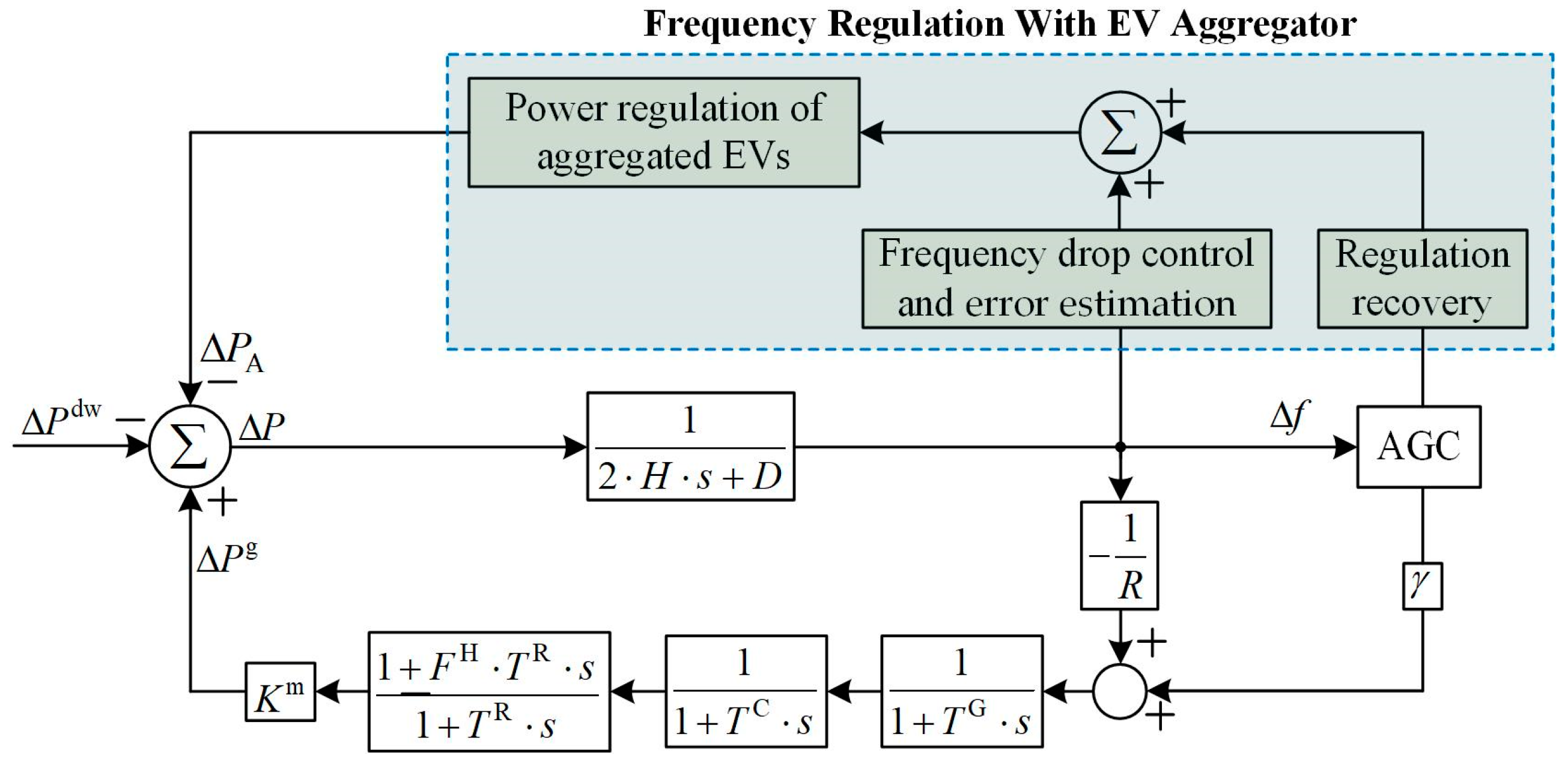
3.2.1. Frequency Regulation with the EV Aggregator

When there is a negative ΔPsys that is caused by a sudden variation in renewable energy, the system frequency deviation experiences a significant variation and then reaches a new equilibrium. The new equilibrium and the frequency nadir of the frequency deviation can be estimated by Equations (29)–(31), respectively. In ref. [35], when the system frequency falls below the allowable frequency variation range, the system frequency with the new equilibrium can be predicted through a number of frequency measurement data.
Δ f nadir = f N R Δ P D R + 1 1 + 1 ς 2 a e ς ω n t nadir
t nadir = 1 ω r tan 1 ω r T R ς ω n T R 1
where TR is the reheat time constant; ωn is the oscillation frequency; and ζ is the damping coefficient.
Δ f ss = R Δ P sys D R + K m
where R is the governor speed regulation; D is the load damping coefficient; and Km is the mechanical power gain factor.
Under a specific frequency deviation Δ f ( t ) , the target power regulation of the EV aggregator is determined by Equation (32).
Δ P A * ( t ) = α ( t ) ( Δ f ( t ) Δ f ε ) + β ( t ) Δ f ( t ) ;   Δ f ( t ) > Δ f ε 0 ; Δ f ε Δ f ( t ) Δ f ε α ( t ) ( Δ f ( t ) + Δ f ε ) + β ( t ) Δ f ( t ) ;   Δ f ( t ) < Δ f ε
where α ( t ) and β ( t ) are the frequency regulation coefficients, which can be determined based on the predicted Δ f ss and Δ f nadir [35].
Then, the target power regulation Δ P A * ( t ) is transformed into the probabilistic control signal [u(t), v(t)] with the following process.
(1) When Δ P A * ( t ) < 0 , the control signal is determined by Equation (33).
Δ P A c 2 i ( t ) = max ( Δ P A * ( t ) , P A c 2 i , dn ( t ) P A ( t ) ) u ( t ) = Δ P A c 2 i ( t ) P A ( t ) P A c 2 i , dn ( t ) Δ P A i 2 d ( t ) = max ( Δ P A * ( t ) Δ P A c 2 i ( t ) , P A c 2 d , dn ( t ) P A c 2 i , dn ( t ) ) v ( t ) = Δ P A i 2 d ( t ) P A c 2 d , dn ( t ) P A c 2 i , dn ( t )
where u ( t ) < 0 and v ( t ) 0 ; and u ( t ) and v ( t ) are, respectively, used to realize the control actions of C2I and I2D.
(2) When Δ P A * ( t ) > 0 , the control signal is determined by Equation (34).
Δ P A d 2 i ( t ) = min ( Δ P A * ( t ) , P A d 2 i , up ( t ) P A ( t ) ) v ( t ) = Δ P A d 2 i ( t ) P A d 2 i , up ( t ) P A ( t ) Δ P A i 2 c ( t ) = min ( Δ P A * ( t ) Δ P A d 2 i ( t ) , P A d 2 c , up ( t ) P A d 2 i , up ( t ) ) u ( t ) = Δ P A i 2 c ( t ) P A d 2 c , up ( t ) P A d 2 i , up ( t )
where u ( t ) > 0 and v ( t ) 0 ; and u ( t ) and v ( t ) are, respectively, used to realize the control actions of I2C and D2I.
(3) When Δ P A * ( t ) = 0 , u ( t ) = 0 and v ( t ) = 0 .

3.2.2. Regulation Error Estimation for the EV Aggregator

Owing to the limited data collection, regulation error may come from three aspects: (a) the probabilistic control action from the control signal, (b) the evaluation error for the regulation capacity of the EV aggregator, and (c) the EV may refuse to respond to the control signal for ensuring traveling requirement. During the frequency regulation, the regulation error can be evaluated with the following process:
(1) When Δ P A * ( t ) < 0 , the selected EVs in CST are controlled to switch to IST, and the selected EVs in IST are controlled to switch to DST. The regulation power from CST to IST is achieved by Equation (35). The regulation power from IST to DST is achieved by Equation (36). Then, the regulation errors under C2I and I2D are estimated by Equation (37).
Δ P A c 2 i ( t ) = j j Ω cst ( t + ) P j ( t + ) j j Ω cst ( t ) P j ( t )
where t + and t are, respectively, the time instants after and before the control action and P A c 2 i ( t ) is the regulation power with C2I.
Δ P A i 2 d ( t ) = j j Ω ist ( t + ) P j ( t + ) j j Ω dst ( t ) P j ( t )
where P A i 2 d ( t ) is the regulation power with I2D.
ε A c 2 i ( t ) = Δ P A c 2 i ( t ) ( P A ( t ) P A c 2 i , dn ( t ) ) u ( t ) ε A i 2 d ( t ) = Δ P A i 2 d ( t ) ( P A c 2 d , dn ( t ) P A c 2 i , dn ( t ) ) v ( t )
where ε A c 2 i ( t ) and ε A i 2 d ( t ) are, respectively, the indicators of regulation errors under C2I and I2D.
(2) When Δ P A * ( t ) > 0 , the selected EVs in DST are controlled to switch to IST, and the selected EVs in IST are controlled to switch to CST. Similarly, the regulation error is evaluated by Equations (38) and (39).
Δ P A d 2 i ( t ) = j j Ω dst ( t + ) P j ( t + ) j j Ω dst ( t ) P j ( t ) Δ P A i 2 c ( t ) = j j Ω cst ( t + ) P j ( t + ) j j Ω cst ( t ) P j ( t )
where Δ P A d 2 i ( t ) and Δ P A i 2 c ( t ) are, respectively, the regulation power with D2I and I2C.
ε A d 2 i ( t ) = Δ P A d 2 i ( t ) ( P A d 2 i , up ( t ) P A ( t ) ) v ( t ) ε A i 2 c ( t ) = Δ P A i 2 c ( t ) ( P A d 2 c , up ( t ) P A d 2 i , up ( t ) ) u ( t )
where ε A d 2 i ( t ) and ε A i 2 c ( t ) are the regulation errors under D2I and I2C, respectively.
To improve regulation accuracy, the regulation error is used to correct the regulation capacity evaluated by Equations (21)–(24). The corrected regulation capacity of the EV aggregator is given by Equation (40) to realize the error correction control during the frequency regulation process.
P A d 2 i , up ( t ) = P A ( t ) + ε A d 2 i ( t ) ( P A d 2 i , up ( t ) P A ( t ) ) Δ P A d 2 i ( t ) P A d 2 c , up ( t ) = P A d 2 i , up ( t ) + ε A i 2 c ( t ) ( P A d 2 c , up ( t ) P A d 2 i , up ( t ) ) Δ P A i 2 c ( t ) P A c 2 i , dn ( t ) = P A ( t ) + ε A c 2 i ( t ) ( P A ( t ) P A c 2 i , dn ( t ) ) Δ P A c 2 i ( t ) P A c 2 d , dn ( t ) = P A c 2 i , dn ( t ) + ε A i 2 d ( t ) ( P A c 2 d , dn ( t ) P A c 2 i , dn ( t ) ) Δ P A i 2 d ( t )

3.2.3. Regulation Recovery of the EV Aggregator

The EV aggregator can respond to the frequency regulation within a short time period. However, the EVs cannot stay in the controlled state due to the traveling requirement. After the system frequency recovers to a steady state, the EV aggregator is able to estimate the regulated power of EVs during the frequency control. This is because the EV aggregator can measure the state change in EV chargers and then use Equation (17) to estimate the number of EVs requiring state recovery. To recover the regulated power of EVs, the AGC control allocates the regulated power of the EV aggregator to conventional generators with the regulation recovery strategy. The conventional generators increase/decrease the power outputs and help the controlled EVs recover to the original state.
To realize the frequency regulation, the EVs are controlled to respond to the system frequency by switching their connecting states. On the one hand, the original charging processes of the controlled EVs are disturbed. On the other hand, the EVs with the original state of IST are controlled to switch to DST and the discharged energy causes insufficient battery energy for the EVs’ traveling requirements. During frequency regulation, the regulated power of the EVs is given by Equation (41).
Δ P A con ( t ) = j j Ω i 2 c ( t ) P j ( t ) + j j Ω c 2 i ( t ) ( P j cr ) + j j Ω i 2 d ( t ) P j ( t ) + j j Ω c 2 d ( t ) ( P j cr + P j ( t ) )
where Δ P A con ( t ) is the total regulated power of all controlled EVs for frequency regulation.
With the generation from conventional generators, the state recovery process of controlled EVs is given as follows:
(1) When Δ P A con ( t ) > 0 , the controlled EVs in CST should be recovered to the original IST. Then, as given by Equation (42), a time delay is introduced to avoid the simultaneous state switch for these controlled EVs.
T con ( t 0 ) = Δ P A con ( t 0 ) γ
where T con ( t 0 ) is the time delay of state recovery for the controlled EVs under up-regulation; t 0 is the starting time of state recovery; and γ is the generation ramp rate.
The EV aggregator broadcast T con ( t 0 ) to all EVs. The controlled EVs in CST receive the time delay and then determine their own time delay with Equation (43) for recovering to IST.
τ j con ( t ) = T con ( t 0 ) π j ( t ) ,   j Ω i 2 c ( t )
where π j ( t ) is a random number generated by a uniform distribution U(0,1); and τ j con ( t ) is the time delay of state recovery for the j-th EV under up-regulation.
(2) When Δ P A con ( t ) < 0 , the controlled EVs in IST should be recovered to the original CST, and the controlled EVs in DST should be recovered to CST. As the discharging process decreases the remaining battery energy, the controlled DST EVs, whose original state is IST, should be recovered to CST for energy acquisition. The time delays for recovering the controlled DST EVs and IST EVs are given by Equation (44).
T con , d ( t 0 ) = Δ P A con , d ( t 0 ) γ T con , c ( t 0 ) = Δ P A con ( t 0 ) Δ P A con , d ( t 0 ) γ
where T con , d ( t 0 ) is the time delay of state recovery for the controlled DST EVs under down-regulation; Δ P A con , d ( t 0 ) is the total power of the controlled DST EVs, as given by Equation (45); and T con , c ( t 0 ) is the time delay of state recovery for the controlled IST EVs or for the controlled DST EVs that have recovered to IST.
Δ P A con , d ( t 0 ) = j j Ω dst ( t 0 ) P j ( t 0 )
The EV aggregator firstly broadcasts T con , d ( t 0 ) to all EVs if T con , d ( t 0 ) > 0 . After the controlled EVs in DST receive the time delay T con , d ( t 0 ) , these EVs determine their own time delay with Equation (46) for recovering to IST. The EV aggregator then broadcasts T con , c ( t 0 ) to all EVs. For the IST EVs whose original state is CST and for the IST EVs that are recovered from DST, these EVs determine their own time delay by using Equation (47) for recovering to CST.
τ j con , d ( t ) = T con , d ( t 0 ) π j ( t ) ,   j Ω dst ( t )
where τ j con , d ( t ) is the time delay of state recovery for the j-th DST EV under down-regulation.
τ j con , c ( t ) = T con , d ( t 0 ) + T con , c ( t 0 ) π j ( t ) ,   j Ω c 2 i ( t ) Ω dst ( t 0 )
where τ j con , c ( t ) is the time delay of state recovery for the j-th IST EV under down-regulation.

4. Case Study and Analysis

4.1. Case Scenario

For a specific power grid, the frequency response can be described by a multimachine-system frequency regulation model [36,37,38]. The multimachine-system frequency regulation model can be aggregated into a single-machine-system frequency regulation model with the analytical method verified in [38]. To verify the proposed frequency regulation strategy with the EV aggregator, a simplified equivalent frequency regulation model of the power system described in Figure 6 is used in the case study. The meanings and values of the frequency regulation parameters in the equivalent model are shown in Table 1 [35].
For the EV aggregator, it manages the EV chargers in communities and public parking areas that have a low charging rate. The EV aggregator is assumed that a number of 10,000 EVs connect to the power grid during a day. Both battery EVs and plug-in EVs are considered in the EV aggregator for frequency regulation. The power regulation is applicable when the EVs connect to these chargers, and the connected EVs have contracted with the EV aggregator for power regulation.
To simulate the connecting and charging processes of EVs, the vehicle survey regarding finishing/starting traveling time is, respectively, regarded as the time at which EVs connect to and disconnect from the power grid [39]. The energy parameters concerning battery capacity and SOC vary within a specific distribution, based on refs. [40,41], are used to simplify the EV simulation. The rated power of the EVs, also determined by EV chargers, usually varies within a range, and usually the real charging or discharging power is less than the rated power due to internal and external conditions [42]. Thus, the time, energy, and preference parameters for regulation are given in Table 2. Based on the values and distributions of EV parameters, the Monte Carlo method is used to extract the parameters for each EV. The time parameters are used to simulate the processes of connecting to and disconnecting from the power grid at the EV charger. It is assumed that each EV begins to charge as soon as it connects to the power grid. The energy parameters are used to simulate the charging process and the SOC variation at the charging terminal. The parameters of regulation preference are used to evaluate the regulation capacity of the EV aggregator. When the frequency deviation violates the frequency deviation threshold, the time interval of the EV aggregator for frequency regulation is 0.5 s. The conventional generator participates in the frequency regulation by increasing or decreasing its power output with a time delay of 30 s.
The EV aggregator only collects the state parameters described by Φ up from EV chargers. The EV aggregator broadcasts the control signal to individual EVs based on collected data and the frequency regulation strategy. The date of traveling requirement, regulation preference, and battery state are stored at the EV charger. The EV charger receives the control signal and determines whether or not to participate in the frequency regulation based on the EV user’s requirements.
Simulations are processed by MATLAB/SIMULINK installed on a laptop with 2.50 GHz Intel Core i7-4710MQ CPU and 8.00 GB RAM.

4.2. Study Results

The time of 18:00 is selected as the starting time for simulation. Considering the significant power fluctuations of wind power, it is assumed that there is a sudden power loss with the value 0.3 p.u. The average execution time for simulation of per 50 s is 25.76 min.
Considering the rapid responding speed of the EV aggregator, the response profile of system frequency is shown in Figure 7. At the time instant of 1.0 s, the system frequency has a significant decrease due to the sudden power loss. Without the EV aggregator, the frequency deviation reaches a minimum value of 0.0678 at 5.1 s, while with the EV aggregator, the frequency deviation reaches a minimum value of 0.0624 at 4.5 s. The EV aggregator is able to decrease the influence from the power loss on frequency deviation. At the 9.3 s time instant, the system frequency recovers to the allowable variation range with the regulation support from the EV aggregator, and then the system frequency deviation varies until reaching a 0.014 p.u. steady state.
Considering the regulation recovery of the EV aggregator, the system frequency regulation results are compared in Figure 8. Without the EV aggregator, the frequency recovery depends on the conventional generation, and the system frequency recovers to the allowable variation range with a time delay of 79.9 s. With the EV aggregator, the frequency deviation varies steadily during the regulation recovery process under the proposed strategy. Compared to the situation without the EV aggregator, there is a time delay when realizing the nondeviation frequency regulation. This is because the discharging process during the frequency regulation causes power loss at the EV charger.
During the frequency control and the regulation recovery, the total power output and the total discharging power are shown in Figure 9. The frequency control process is finished within 10 s, and the regulation recovery starts at 30 s and finishes within 350 s. It is clear that total power output and the total discharging power of the EV aggregator decrease significantly during the frequency control process. This is because the controllable EVs in CST are controlled to switch to IST, and even a proportion of the EVs in IST are controlled to switch to DST. When the conventional generators receive the AGC signal, the regulation recovery begins. The conventional generation increases the power output with the AGC control, and the EVs in DST first recover to IST gradually, and then the controlled IST EVs and the IST EVs recover to CST gradually. For the IST EVs recovered from DST, the discharging process during the frequency regulation causes the lower SOC value than the EVs’ traveling requirement, and these EVs should recover to CST until the SOC values stratify their requirements. After the EVs in DST recover to CST, these EVs will switch to IST with the charging process of tens of seconds, and there will be a power decrease in the total power output after the total power reaches a maximum value.
Owing to limited data collection, the proportion of EVs for participating in different frequency regulation modes is estimated by the EV aggregator. To verify the influence of the estimation error on the frequency regulation, the system frequency deviation profile under different proportions of EVs for participating in different regulation modes is shown in Figure 10. Under the estimation errors of 0%, 5%, 10%, 20%, and 40%, the proposed frequency regulation strategy with error correction control effectively decreases the adverse influence from the estimation error.

5. Conclusions

The high penetration of renewable energy in the power grid incurs unpredictable frequency deviation. Existing modeling and control methods for EV aggregators are not applicable for frequency regulation with the limited data collection for EVs. This paper develops a frequency regulation strategy for EV aggregators without acquiring the private data of EVs, such as the EV traveling data and the regulation preference data. The probabilistic control and error correction are applied to improve the frequency regulation performance. The regulation recovery combined with the conventional generators is used to ensure EV users’ requirements for traveling and regulation preference. The conclusions are summarized as follows:
(1)
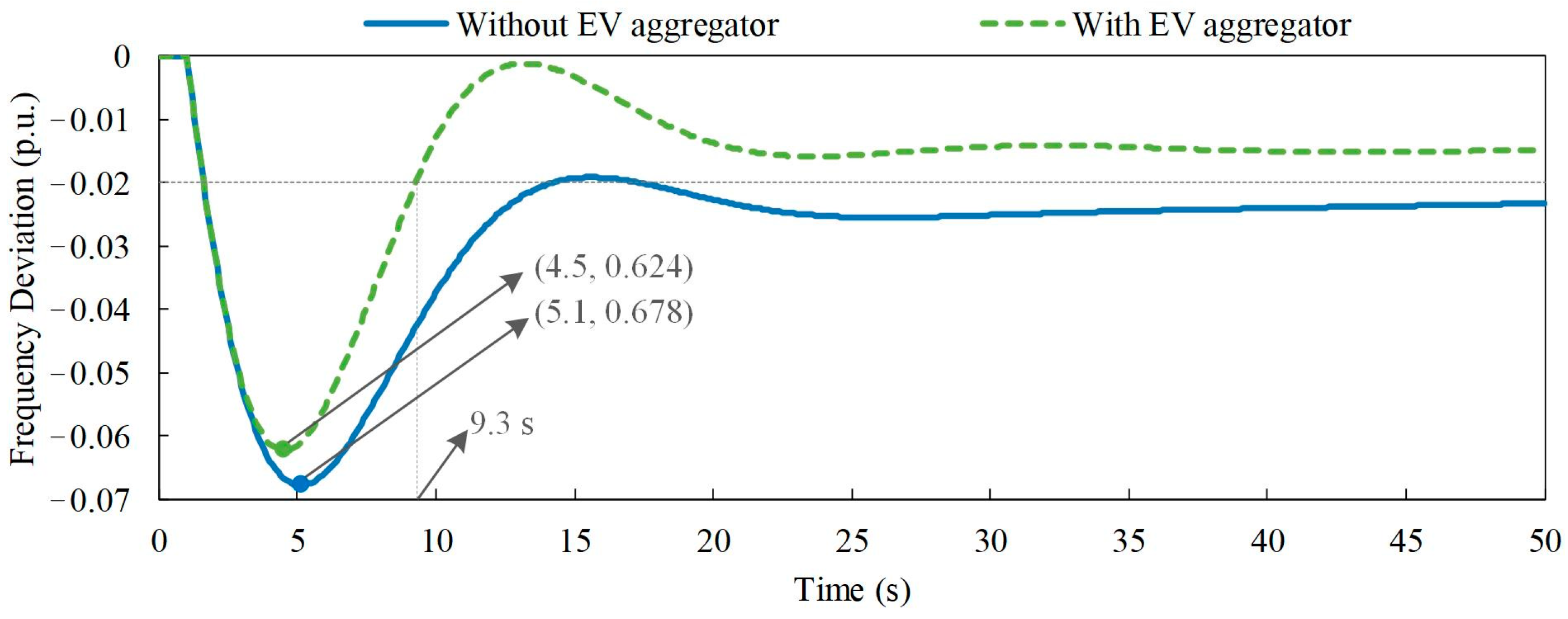
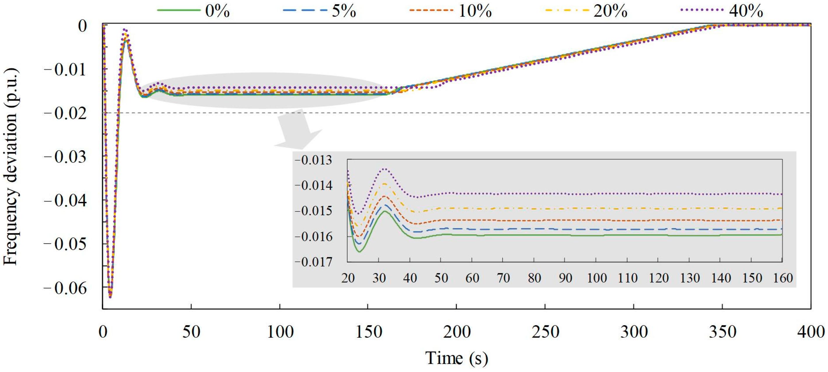
When a frequency deviation occurs, the proposed frequency regulation strategy can effectively recover the system frequency to the allowable variation range and help improve the frequency stability of the power system.
(2)
With limited data collection, the regulation capacity of the EV aggregator is estimated without acquiring the data for EV traveling, battery state, and regulation preferences. During frequency regulation, the error correction control for the EV aggregator is developed to decrease the influence from the estimation error, and the regulation requirements for each EV are ensured with the self-adaptive probabilistic control at the EV charger.
(3)
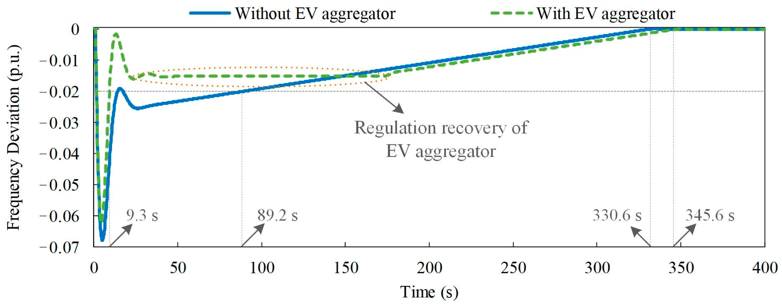
With the simplified probabilistic control signal and conventional generation, the time delay is added to recover the controlled EVs to their own original connecting state. During the frequency recovery, the system frequency varies steadily without the secondary disturbance from the simultaneous state switch of controlled EVs for recovery.
In the future, we will investigate how to attract more EV users to participate in the frequency regulation under the electricity market. The incentive mechanism for different EV users needs to be established considering the users’ preference, the battery degradation and the market uncertainties.

Author Contributions

Conceptualization F.Z. and M.W.; methodology, F.Z., Z.W. and M.W.; software, F.Z. and G.S.; validation, F.Z., Z.W. and M.W.; formal analysis, F.Z. and G.S.; investigation, F.Z., Z.W. and M.W.; resources, F.Z. and H.H.; data curation, F.Z., G.S. and H.H.; writing—original draft preparation, F.Z. and M.W.; writing—review and editing, F.Z., Z.W. and G.S. All authors have read and agreed to the published version of the manuscript.

Funding

This research was funded by National Natural Science Foundation of China, grant number 52107099.

Data Availability Statement

The data presented in this study are available on request from the corresponding author.

Conflicts of Interest

The authors declare no conflict of interest.

Nomenclature

Abbreviations:
EVElectric vehicle.
SOCState of charge.
CSTCharging state.
ISTIdle state.
DSTDischarging state.
USTUnused state.
C2IControl action from CST to IST.
I2DControl action from IST to DST.
D2IControl action from DST to IST.
I2CControl action from IST to CST.
C2DControl action from CST to IST and then IST to DST.
Parameters of indices:
tIndex of time instants.
Δ t Time interval.
jIndex of EV chargers.
Parameters of individual EV and EV charger:
Q j EV battery capacity.
P j c r / P j d r EV rated charging/discharging power.
η j c r / η j d r EV charging/discharging efficiency.
θ j Indicator of the connecting state of EV charger.
t j i n i EV connecting time instant with EV charger.
t j c n t Time instant for EV connection at the EV charger.
t j f s h EV leaving time instant from EV charger.
S j i n i EV initial SOC when connecting the EV charger.
S j r e q Required SOC for EV traveling.
S j m i n / S j m a x Minimum/maximum SOC of EV for frequency regulation.
T j l a x EV charging laxity.
δ j c / δ j d Binary indicators for EV preference for C2I and I2C/I2D and D2I.
Δ P j c 2 i / P j i 2 d Available regulation capacity from C2I/I2D for power decrease.
Δ P j d 2 i / P j i 2 c Available regulation capacity from D2I/I2C for power increase.
P j ( t ) Real-time power output of EV charger.
P j u p ( t ) / P j d n ( t ) Upper/Lower boundary of EV’s power regulation range.
S j ( t ) Real-time SOC of EV battery at the EV charger.
S j u p ( t ) / S j d n ( t ) Upper/lower boundary of EV’s SOC variation range.
δ j ( t ) Indicator of EV for control action of connecting state.
π j ( t ) Binary indicator of EV of switching into the forced CST.
Parameters of EV aggregator:
Ω ( t ) Set of indices of all EV chargers in the EV aggregator.
Ω c s t ( t ) / Ω i s t ( t ) Set of indices of EV chargers in CST/IST in the EV aggregator.
Ω d s t ( t ) / Ω u s t ( t ) Set of indices of EV chargers in DST/UST in the EV aggregator.
N c s t ( t ) / N i s t ( t ) Number of EVs in CST/IST in the EV aggregator.
N d s t ( t ) / N u s t ( t ) Number of EVs in DST/UST in the EV aggregator.
Ω c 2 i ( t ) / Ω i 2 c ( t ) Set of indices of EV chargers with C2I/I2C control.
Ω i 2 d ( t ) / Ω c 2 d ( t ) Set of indices of EV chargers with I2D/C2D control.
N c 2 i ( t ) / N i 2 c ( t ) Number of EV chargers with C2I/I2C control.
N i 2 d ( t ) / N c 2 d ( t ) Number of EV chargers with I2D/C2D control.
P A ( t ) Power output of EV aggregator.
P A d 2 i , u p ( t ) Regulation capacity of EV aggregator with D2I.
P A d 2 c , u p ( t ) Regulation capacity of EV aggregator with D2I and I2C.
P A c 2 i , u p ( t ) Regulation capacity of EV aggregator with C2I.
P A c 2 d , u p ( t ) Regulation capacity of EV aggregator with C2I and I2D.
Parameters of frequency regulation:
Δ f ( t ) System frequency deviation.
α ( t ) , β ( t ) Frequency regulation coefficients.
[ Δ f ε , Δ f ε ] Allowable variation range of system frequency.
[u(t), v(t)]Probabilistic control signal for EV aggregator.
P A * ( t ) Target power regulation of EV aggregator
Δ P A c 2 i ( t ) Required power regulation with C2I.
Δ P A i 2 d ( t ) Required power regulation with I2D.
Δ P A d 2 i ( t ) Required power regulation with D2I.
Δ P A i 2 c ( t ) Required power regulation with I2C.

References

  1. Li, J.; Gao, Z.; Mu, G.; Fan, X.; Zhang, Z.; Zou, J. Research on the Control Strategy of Energy Storage Participation in Power System Frequency Regulation. Int. Trans. Electr. Energ. Syst. 2020, 27, 12676. [Google Scholar] [CrossRef]
  2. Ma, Y.; Hu, Z.; Song, Y. Hour-Ahead Optimization Strategy for Shared Energy Storage of Renewable Energy Power Stations to Provide Frequency Regulation Service. IEEE Trans. Sustain. Energy 2022, 13, 2331–2342. [Google Scholar] [CrossRef]
  3. Li, S.; Lu, J.; Qin, S.; Hu, Y.; Fang, F. Data-Driven Lumped Dynamic Modelling of Wind Farm Frequency Regulation Characteristics. IET Cyber-Phys. Syst. 2022, 7, 147–156. [Google Scholar] [CrossRef]
  4. Global EV Outlook 2022. International Energy Agency. Available online: https://www.iea.org/reports/global-ev-outlook-2022 (accessed on 15 October 2022).
  5. Wu, F.; Yang, J.; Zhan, X.; Liao, S.; Xu, J. The Online Charging and Discharging Scheduling Potential of Electric Vehicles Considering the Uncertain Responses of Users. IEEE Trans. Power Syst. 2021, 36, 1794–1806. [Google Scholar] [CrossRef]
  6. Ye, Z.; Gao, Y.; Yu, N. Learning to Operate an Electric Vehicle Charging Station Considering Vehicle-Grid Integration. IEEE Trans. Smart Grid 2022, 13, 3038–3048. [Google Scholar] [CrossRef]
  7. Hoque, M.M.; Khorasany, M.; Razzaghi, R.; Jalili, M.; Wang, H. Network-Aware Coordination of Aggregated Electric Vehicles Considering Charge-Discharge Flexibility. IEEE Trans. Smart Grid 2022, 1–15. [Google Scholar] [CrossRef]
  8. Coban, H.H.; Lewicki, W.; Sendek-Matysiak, E.; Łosiewicz, Z.; Drożdż, W.; Miśkiewicz, R. Electric Vehicles and Vehicle–Grid Interaction in the Turkish Electricity System. Energies 2022, 15, 8218. [Google Scholar] [CrossRef]
  9. Tripathi, S.; Singh, V.P.; Kishor, N.; Pandey, A. Load Frequency Control of Power System Considering Electric Vehicles’ Aggregator With Communication Delay. Int. J. Electr. Power Energy Syst. 2023, 145, 108697. [Google Scholar] [CrossRef]
  10. Diaz-Londono, C.; Vuelvas, J.; Gruosso, G.; Correa-Florez, C.A. Remuneration Sensitivity Analysis in Prosumer and Aggregator Strategies by Controlling Electric Vehicle Chargers. Energies 2022, 15, 6913. [Google Scholar] [CrossRef]
  11. Wang, M.; Mu, Y.; Li, F.; Jia, H.; Li, X.; Shi, Q.; Jiang, T. State Space Model of Aggregated Electric Vehicles for Frequency Regulation. IEEE Trans. Smart Grid 2020, 11, 981–994. [Google Scholar] [CrossRef]
  12. Dong, C.; Xiao, Q.; Wang, M.; Morstyn, T.; McCulloch, M.D.; Jia, H. Distorted Stability Space and Instability Triggering Mechanism of EV Aggregation Delays in the Secondary Frequency Regulation of Electrical Grid-Electric Vehicle System. IEEE Trans. Smart Grid 2020, 11, 5084–5098. [Google Scholar] [CrossRef]
  13. Le, F.C.; Kara, E.C.; Moura, S. PDE Modeling and Control of Electric Vehicle Fleets for Ancillary Services: A Discrete Charging Case. IEEE Trans. Smart Grid 2018, 9, 573–581. [Google Scholar] [CrossRef]
  14. Guo, Z.; Zhou, Z.; Zhou, Y. Impacts of Integrating Topology Reconfiguration and Vehicle-to-Grid Technologies on Distribution System Operation. IEEE Trans. Sustain. Energy 2020, 11, 1023–1032. [Google Scholar] [CrossRef]
  15. Quijano, D.A.; Melgar-Dominguez, O.D.; Sabillon, C.; Venkatesh, B.; Padilha-Feltrin, A. Increasing Distributed Generation Hosting Capacity in Distribution Systems via Optimal Coordination of Electric Vehicle Aggregators. IET Gener. Transm. Distrib. 2021, 15, 359–370. [Google Scholar] [CrossRef]
  16. Amamra, S.A.; Marco, J. Vehicle-to-Grid Aggregator to Support Power Grid and Reduce Electric Vehicle Charging Cost. IEEE Access 2019, 7, 178528–178538. [Google Scholar] [CrossRef]
  17. Vatandoust, B.; Ahmadian, A.; Golkar, M.A.; Elkamel, A.; Almansoori, A.; Ghaljehei, M. Risk-Averse Optimal Bidding of Electric Vehicles and Energy Storage Aggregator in Day-Ahead Frequency Regulation Market. IEEE Trans. Power Syst. 2019, 34, 2036–2047. [Google Scholar] [CrossRef]
  18. Deng, X.; Zhang, Q.; Li, Y.; Sun, T.; Yue, H. Hierarchical Distributed Frequency Regulation Strategy of Electric Vehicle Cluster Considering Demand Charging Load Optimization. IEEE Trans. Ind. Appl. 2022, 58, 720–731. [Google Scholar] [CrossRef]
  19. Liu, H.; Huang, K.; Wang, N.; Qi, J.; Wu, Q.; Ma, S.; Li, C. Optimal Dispatch for Participation of Electric Vehicles in Frequency Regulation Based on Area Control Error and Area Regulation Requirement. Appl. Energy 2019, 240, 46–55. [Google Scholar] [CrossRef]
  20. Liu, H.; Qi, J.; Wang, J.; Li, P.; Li, C.; Wei, H. EV Dispatch Control for Supplementary Frequency Regulation Considering the Expectation of EV Owners. IEEE Trans. Smart Grid 2018, 9, 3763–3772. [Google Scholar] [CrossRef] [Green Version]
  21. Kolawole, O.; Al-Anbagi, I. Electric Vehicles Battery Wear Cost Optimization for Frequency Regulation Support. IEEE Access 2019, 7, 130388–130398. [Google Scholar] [CrossRef]
  22. Cai, S.; Matsuhashi, R. Model Predictive Control for EV Aggregators Participating in System Frequency Regulation Market. IEEE Access 2021, 9, 80763–80771. [Google Scholar] [CrossRef]
  23. Wang, M.; Ge, L.; Dong, C.; Xiao, Q.; An, H.; Mu, Y. Smoothing Control of Wind Power Fluctuations With Battery Energy Storage System of Electric Vehicles. Int. Trans. Electr. Energy Syst. 2021, 31, e12606. [Google Scholar] [CrossRef]
  24. Kaur, K.; Singh, M.; Kumar, N. Multiobjective Optimization for Frequency Support Using Electric Vehicles: An Aggregator-Based Hierarchical Control Mechanism. IEEE Syst. J. 2019, 13, 771–782. [Google Scholar] [CrossRef]
  25. Ko, K.S.; Sung, D.K. The Effect of EV Aggregators With Time-Varying Delays on the Stability of a Load Frequency Control System. IEEE Trans. Power Syst. 2018, 33, 669–680. [Google Scholar] [CrossRef]
  26. Scarabaggio, P.; Carli, R.; Cavone, G.; Dotoli, M. Smart Control Strategies for Primary Frequency Regulation through Electric Vehicles: A Battery Degradation Perspective. Energies 2020, 13, 4586. [Google Scholar] [CrossRef]
  27. Yan, G.; Liu, D.; Li, J.; Mu, G. A Cost Accounting Method of the Li-ion Battery Energy Storage System for Frequency Regulation Considering the Effect of Life Degradation. Prot. Control. Mod. Power Syst. 2018, 3, 4. [Google Scholar] [CrossRef] [Green Version]
  28. Zhou, C.; Qian, K.; Allan, M.; Zhou, W. Modeling of the Cost of EV Battery Wear due to V2G Application in Power Systems. IEEE Trans. Energy Convers. 2011, 26, 1041–1050. [Google Scholar] [CrossRef]
  29. Farzin, H.; Fotuhi-Firuzabad, M.; Moeini-Aghtaie, M. A Practical Scheme to Involve Degradation Cost of Lithium-ion Batteries in Vehicle-to-Grid Applications. IEEE Trans. Sustain. Energy 2016, 7, 1730–1738. [Google Scholar] [CrossRef]
  30. Han, S.; Han, S.; Aki, H. A Practical Battery Wear Model for Electric Vehicle Charging Applications. Appl. Energy 2014, 113, 1100–1108. [Google Scholar] [CrossRef]
  31. Liu, C.; Wang, X.; Wu, X.; Guo, J. Economic Scheduling Model of Microgrid Considering the Lifetime of Batteries. IET Gener. Transm. Distrib. 2017, 11, 759–767. [Google Scholar] [CrossRef]
  32. Lipu, M.S.H.; Hannan, M.A.; Hussain, A.; Hoque, M.M.; Ker, P.J.; Saad, M.H.M.; Ayob, A. A Review of State of Health and Remaining Useful Life Estimation Methods for Lithium-ion Battery in Electric Vehicles: Challenges and Recommendations. J. Clean. Prod. 2018, 205, 115–133. [Google Scholar] [CrossRef]
  33. Stroe, D.I.; Knap, V.; Swierczynski, M.; Stroe, A.I.; Teodorescu, R. Operation of a Grid-Connected Lithium-ion Battery Energy Storage System for Primary Frequency Regulation: A Battery Lifetime Perspective. IEEE Trans. Ind. Appl. 2017, 53, 430–438. [Google Scholar] [CrossRef]
  34. Song, M.; Amelin, M. Purchase Bidding Strategy for a Retailer With Flexible Demands in Day-Ahead Electricity Market. IEEE Trans. Power Syst. 2017, 32, 1839–1850. [Google Scholar] [CrossRef]
  35. Shi, Q.; Cui, H.; Li, F.; Liu, Y.; Ju, W.; Sun, Y. A Hybrid Dynamic Demand Control Strategy for Power System Frequency Regulation. CSEE J. Power Energy Syst. 2017, 3, 176–185. [Google Scholar] [CrossRef]
  36. Aik, D.L.H. A General-Order System Frequency Response Model Incorporating Load Shedding: Analytic Modeling and Applications. IEEE Trans. Power Syst. 2006, 21, 709–717. [Google Scholar] [CrossRef]
  37. Sigrist, L.; Egido, I.; Rouco, L. A Method for the Design of UFLS Schemes of Small Isolated Power Systems. IEEE Trans. Power Syst. 2012, 27, 951–958. [Google Scholar] [CrossRef]
  38. Shi, Q.; Li, F.; Cui, H. Analytical Method to Aggregate Multi-Machine SFR Model With Applications in Power System Dynamic Studies. IEEE Trans. Power Syst. 2018, 33, 6355–6367. [Google Scholar] [CrossRef]
  39. Yao, W.; Zhao, J.; Wen, F.; Xue, Y.; Ledwich, G. A Hierarchical Decomposition Approach for Coordinated Dispatch of Plug-in Electric Vehicles. IEEE Trans. Power Syst. 2013, 28, 2768–2778. [Google Scholar] [CrossRef]
  40. Mukherjee, J.C.; Gupta, A. Distributed Charge Scheduling of Plug-in Electric Vehicles Using Inter-Aggregator Collaboration. IEEE Trans. Smart Grid 2017, 8, 331–341. [Google Scholar] [CrossRef]
  41. Guo, Y.; Liu, W.; Wen, F.; Salam, A.; Mao, J.; Li, L. Bidding Strategy for Aggregators of Electric Vehicles in Day-Ahead Electricity Markets. Energies 2017, 10, 144. [Google Scholar] [CrossRef]
  42. Han, S.; Han, S.; Sezaki, K. Estimation of Achievable Power Capacity From Plug-in Electric Vehicles for V2G Frequency Regulation: Case Studies for Market Participation. IEEE Trans. Smart Grid 2011, 2, 632–641. [Google Scholar] [CrossRef]
Figure 1. Regulation capacity of an EV with regulation mode 1: (a) SOC upper and lower boundaries; (b) power upper and lower boundaries.
Energies 16 00848 g001
Figure 2. Regulation capacity of an EV with regulation mode 2: (a) SOC upper and lower boundaries; (b) power upper and lower boundaries.
Energies 16 00848 g002
Figure 3. Regulation capacity of an EV with regulation mode 3: (a) SOC upper and lower boundaries; (b) power upper and lower boundaries.
Energies 16 00848 g003
Figure 4. Frequency regulation characteristics of the EV aggregator.
Energies 16 00848 g004
Figure 5. Frequency regulation process with the EV aggregator.
Energies 16 00848 g005
Figure 6. Equivalent frequency regulation model of the power system with the EV aggregator.
Energies 16 00848 g006
Figure 7. System frequency regulation without and with the EV aggregator.
Energies 16 00848 g007
Figure 8. System frequency regulation without and with regulation recovery by the EV aggregator.
Energies 16 00848 g008
Figure 9. Total power output and total discharging power of the EV aggregator during the system frequency regulation with regulation recovery.
Energies 16 00848 g009
Figure 10. Frequency regulation by the EV aggregator under different regulation preference rates.
Energies 16 00848 g010
Table 1. Parameters of the equivalent-system frequency regulation model.
ParameterValue
Inertia constant H4.44 s
Load damping coefficient D1.0
Governor speed regulation R0.09
Governor time constant TG0.2 s
Steam chest time constant TC0.3 s
Reheat time constant TR12 s
High-pressure turbine fraction FH0.17
Mechanical power gain factor Km1.0
Allowable frequency deviation Δ f ε 0.02
Table 2. Time, energy, and preference parameters of aggregated EVs.
ParameterValue/Distribution
Connecting time instant with power grid t j i n i N (−6.5, 3.4)∈[0, 5.5]
N (17.5, 3.4)∈[5.5, 24]
Disconnecting time instant with power grid t j f s h N (8.9, 3.4)∈[0, 20.9]
N (32.9, 3.4)∈[20.9, 24]
Initial SOC at connecting time instant S j i n i N (0.3, 0.05)∈[0.2, 0.4]
Required SOC for traveling S j r e q N (0.8, 0.03)∈[0.7, 0.9]
Minimum/maximum SOC value S j m i n / S j m a x 1.0/0.1
Battery capacity QjU (20.0, 30.0) kWh
Rated charging/discharging power P j c r / P j d r U (5.0, 7.0) kW
Charging/discharging efficiency η j c r / η j d r U (0.88, 0.95)
Proportion of EVs for only participating C2I and I2C/proportion of EVs for participating all four frequency regulation modes φ c / φ d 0.4/0.3
Disclaimer/Publisher’s Note: The statements, opinions and data contained in all publications are solely those of the individual author(s) and contributor(s) and not of MDPI and/or the editor(s). MDPI and/or the editor(s) disclaim responsibility for any injury to people or property resulting from any ideas, methods, instructions or products referred to in the content.

