Article

Study on the Lightning Protection Performance for a 110 kV Non-Shield-Wired Overhead Line with Anti-Thunder and Anti-Icing Composite Insulators

1
Disaster Prevention and Reduction Center of State Grid Hunan Electric Power Corporation, Changsha 410129, China
2
State Key Laboratory of Power Transmission Equipment & System Security and New Technology of Chongqing University, Chongqing 400044, China
*
Author to whom correspondence should be addressed.
Energies 2023, 16(2), 815; https://doi.org/10.3390/en16020815
Submission received: 10 December 2022 / Revised: 26 December 2022 / Accepted: 6 January 2023 / Published: 10 January 2023
(This article belongs to the Topic High Voltage Systems and Smart Technologies)

Abstract

:
Due to micro landforms and climate, the 110 kV transmission lines crossing the mountain areas are exposed to severe icing conditions for both their high voltage (HV) conductors and shield wires during the winter. Ice accumulation on the shield wire causes excessive sag, which leads to a reduced clearance between earth and HV wires, and could eventually result in tripping of the line due to phase-to-ground flashover. Due to the lack of effective de-icing techniques for the shield wires, removing them completely from the existing overhead line (OHL) structure becomes a reasonable solution to prevent icing accidents. Nevertheless, the risk of exposure to lightning strikes increased significantly after the shield wires were removed. In order to cope with this, the anti-thunder and anti-icing composite insulator (AACI) is installed on the OHLs. In this article, the 110 kV transmission line without shield wire is considered. The shielding failure after installation of the AACIs is studied using the lightning strike simulation models established in the ATP software. The lightning stroke flashover tests are carried out to examine the shielding failures on various designs for the AACIs. Assuming the tower’s earth resistance is 30 Ω, the LWL of back flashover and direct flashover are 630.88 kA and 261.33 kA, respectively, after the installation of AACIs on an unearthed OHL. Due to the unique mechanism of the AACI, the operational voltage level and the height of the pylon have a neglectable influence on its lightning withstand level (LWL). When the length of the parallel protective gap increases from 450 mm to 550 mm, the lightning trip-out rate decreases from 0.104 times/100 km·a to 0.014 times/100 km·a, and the drop rate reaches 86.5%. Therefore, increasing the gap distance for the AACI to provide additional clearance is proven to be an effective method to reduce the shielding failure rates for non-shield-wired OHLs.

1. Introduction

China is one of the countries whose power transmission lines suffer the most severe icing disasters. Transmission line tripping accidents caused by icing are reported throughout the majority of areas within China. These accidents have caused significant financial losses as well as social impacts [1,2]. Research in China has been focused on ice disaster prevention for power grids in the recent decade, especially after the major power system blackout in 2008. The reconductoring of OHLs to provide icing prevention, as well as the development of de-icing techniques, are merged, which have significantly improved the ability of OHLs to withstand extreme icing conditions and disasters [3,4,5]. In particular, relatively mature techniques have been deployed widely for de-icing within major utility companies such as State Grid Corporation of China (SGCC) and China Southern Grid (CSG). Encouraging results are achieved to de-ice high voltage (HV) conductors through fixed or mobile direct current (DC) sources, which generate a large current to heat the conductor and melt the ice with optimized schemes. However, it is not possible to use the same method to de-ice the shield wire due to the nature that it is connected directly to the ground.
Ice accumulation on the shield wire increases the weight load, causes excessive sag and reduces the clearance to its adjacent HV conductors, which can lead to flashover and tripping accidents. Moreover, severe ice accumulation on the shield wire can breach its knee-point of mechanical loading, which causes permanent damage or even broken strands on the shield wire. In particular, transmission lines across mountain areas are subject to heavy icing conditions due to the effect of microtopography and microclimate; therefore, they are exposed to a high risk of phase-to-earth flashovers. In order to prevent this, the option of removing the shield wire from the OHL structure is proposed [6,7,8]. The drawback of removing the shield wire is the lack of protection against lightning strikes, which directly leads to an increased level of tripping accidents during foul weather [9]. In order to reduce lightning strike failures of transmission lines, surge arresters have been installed on transmission lines since the 1980s [10,11,12]. The onsite experience has proved that the surge arrester significantly improves the LWL of the OHLs. Especially for the OHL spans suffering vigorous lightning activities or experiencing high grounding resistivities, promising results are achieved by introducing the surge arresters [13,14,15].
Based on this, it is proposed to replace the shield wires with anti-thunder and anti-icing composite insulators [16,17,18,19,20]. With the support from the headquarters’ key project within the SGCC, this work examines the withstand performance against lightning after the AACIs were installed on non-shield-wired OHLs. Both the direct flashover and the back flashover are studied subject to various designs of AACIs through electromagnetic transient simulations. The characteristics of the shielding failure rates against the different designs of the AACI are summarized. Theoretical guidelines are provided for the engineering design of AACIs when replacing the shield wires of OHLs.

2. Simulation Model

This paper uses ATP software to simulate the LWL of non-shield-wired OHLs. Models to simulate OHLs, towers, ground resistance, and AACIs are established according to the typical 110 kV transmission lines within SGCC.

2.1. Lightning Current Model

The Heidler model integrated within the ATP software package is used to compute the lightning current, which is based on the following formula:
i f ( t ) = I 0 η ( t / τ 1 ) n 1 + ( t / τ 1 ) n e t / τ 2 ,
where I0 is the amplitude of lightning current; η is the lightning peak correction factor; n is the current steepness factor; τ1 and τ2 are the wave head and wave tail time, respectively, taking typical values of 2.6 μs and 50 μs, respectively; negative lightning polarity is assumed; the surge impedance of the lightning channel is assumed to be 400 Ω.

2.2. Transmission Line Model

The Jmarti model is used for the transmission lines [21,22], which gives a better representation of the actual transmission lines. This model is also capable of taking into account the frequency characteristics as well as the skin effect on lightning currents. The model is established to model the 110 kV non-shield-wired OHLs. The HV conductors of the transmission line are assumed to be LGJ-300/40 steel-cored aluminum strands. The removal of the shield wire for the OHL does not change the tower structure, which is assumed as a widely deployed ‘cat-head’-like tower.
When the lightning wave propagates along the HV conductors, the variation in its frequency not only requires amended electrical parameters on the line’s model but also results in pulsating corona discharges on the HV conductors when the magnitude of lightning overvoltage exceeds a certain value. The corona discharge attenuates the lightning overvoltage when it propagates along the transmission line. Therefore, adding a corona simulation model which reflects the impulse corona discharges based on the line model is necessary. In this paper, the modified Peek formula is used to calculate the surface potential gradient as well as the applied voltage for corona inceptions:
E c = 24.5 m δ f ( 1 + 0.65 / ( δ r ) 0.38 ) ,
U c = E c r ln 2 h r ,
In the above formula, m refers to the roughness of the conductor, which is assumed to be 0.82 in this particular case, and δ is the relative air density. The value of f is relevant to the voltage polarity. Positive polarity gives an f value of 0.5, while negative polarity gives an f value of 1.0. r and h are the radii and average height of the conductor, respectively, in cm. The corona inception voltage and mutual capacitance between each phase are obtained from the actual conductor parameters on the 110 kV non-shield-wired OHLs.

2.3. Earth Resistance Model
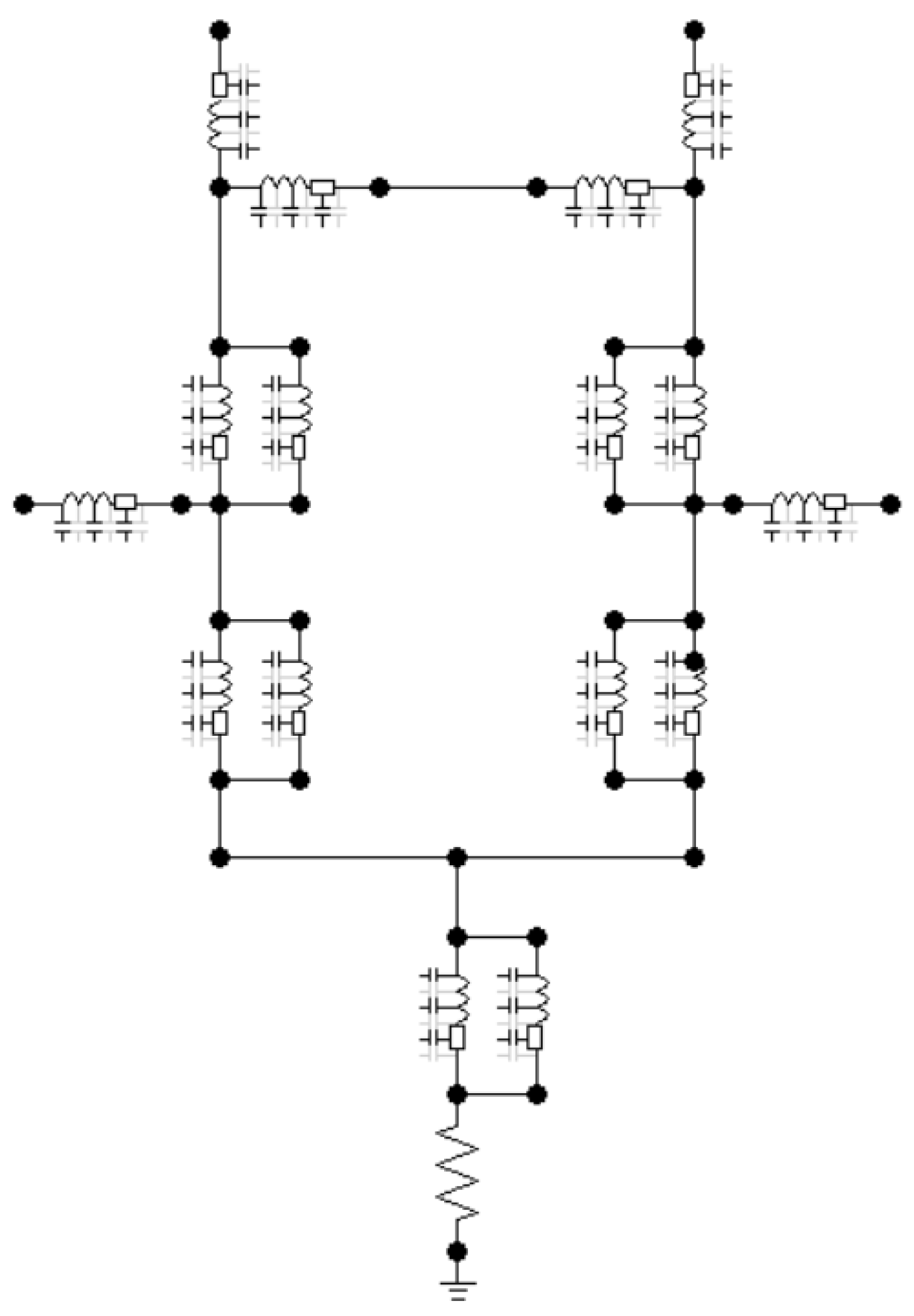
Previous works have shown that the earth resistance is the parameter that has the most significant influence on the LWL of the back flashover, among many other factors. The earth resistance of the tower varies in different regions due to the varied topography. The International Electrotechnical Commission (IEC) considers that the ionization of soil should be considered in the grounding model, and the recommended calculation formula is as follows [23,24]:
R cj = R 0 / 1 + I f / I g ,
I g = ρ E g 2 π R 0 2
where R0 is nominal earth resistance, in Ω; If is the lightning current flowing into the ground, in kA; Ig is the critical current value of soil ionization, in kA; ρ Is soil resistivity, in Ω·m; Eg is the electric field strength of soil ionization, assumes to be 400 kV/m. In this paper, the TACSRes component module is used to build a resistance model, which better reflects the ionization effect of soil caused by the excessive lightning current flowing through the grounding device.

2.4. Tower Model

The lossless multi-wave impedance model is used to simulate the pylon [25,26]. The wave response characteristics calculated by this model are conformed with the measurements from the actual tower. In this paper, taking the ‘cat-head’ tower as an example, the effects of the tower body, support, and cross arm are taken into consideration. The corresponding wave impedance of each component is calculated independently, considering its size and the geometric function of the tower itself. A multi-wave impedance tower model, which is classified as the distributed parameter model, is thereby established (as shown in Figure 1).

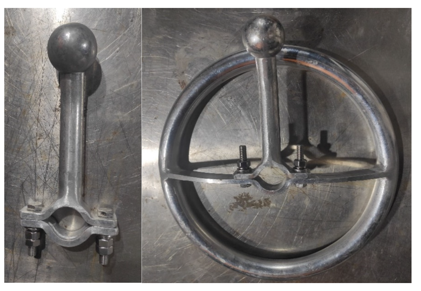
2.5. Anti-Thunder and Anti-Icing Composite Insulator Model

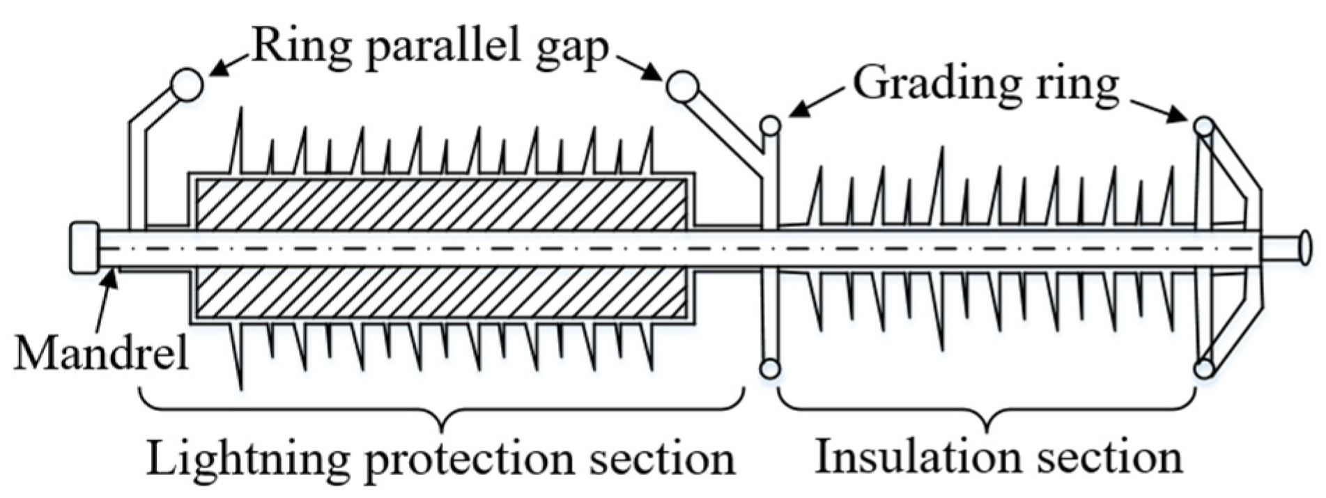
2.5.1. Anti-Thunder and Anti-Icing Composite Insulator

The structure of the AACI is shown in Figure 2. The whole insulator consists of an insulation section and a lightning protection section. The design of the insulation section is the same as the composite insulator. In contrast, the lightning protection section is composed of a zinc oxide surge arrester connected through the core rod; therefore, it can provide electrical insulation as well as lightning protection. The lightning protection section, comprised of surge arresters, is equipped with parallel protection gaps at both ends. When encountering high magnitude over-voltage, the parallel air gap breaks down to relieve the excessive transient overvoltage and protect the surge arresters. The composite surge arrester is suspended in a way that the insulation section is connected to the conductor, while the lightning protection section is connected to the pole and tower cross arm. The electric field simulation results show that under normal operating conditions, the insulation section withstands approximately 83% of the nominal voltage, which plays a significant role in providing electrical insulation.
When fitted to the non-shield-wired OHLs, the insulating section of the AACI withstands the majority of the voltage stress. When lightning strikes hit the tower or directly hit the conductor, the overvoltage first breaks down the air gap between the grading rings of the insulation section, and then the lightning current flows through the arrester in the lightning protection section. The arrester’s zinc oxide resistor absorbs the excessive energy induced by lightning, thus limiting the induced overvoltage. The lightning current is only sustained for tens of microseconds, after which the nominal voltage is applied to the arrester. Due to the nonlinear characteristics of the zinc oxide resistor, the current is limited to its minimal, which makes it difficult to maintain the nominal arcing between grading rings. Therefore, the arcing between grading rings is extinguished, which restores the insulation performance, and returns the insulator to its normal operation status. This summarizes the working principle and functional mechanism of composite surge arresters. It is obvious that the design of a lightning arrester in the lightning protection section can effectively prevent the flashover across the whole insulator and reduce the probability of the protection tripping for the transmission line. In order to ensure the reliable operation of the arrester and prevent it from being damaged by the extreme amplitude of lightning current, a rod–rod parallel protection gap is fitted at both ends of the lightning protection section. When the lightning current conducts through the arrester, it produces a specific residual voltage. If the amplitude of the lightning current increases, the residual voltage of the arrester also increases. When the residual voltage exceeds a specific value, the parallel protection air gap breaks down to provide protection to the surge arresters.

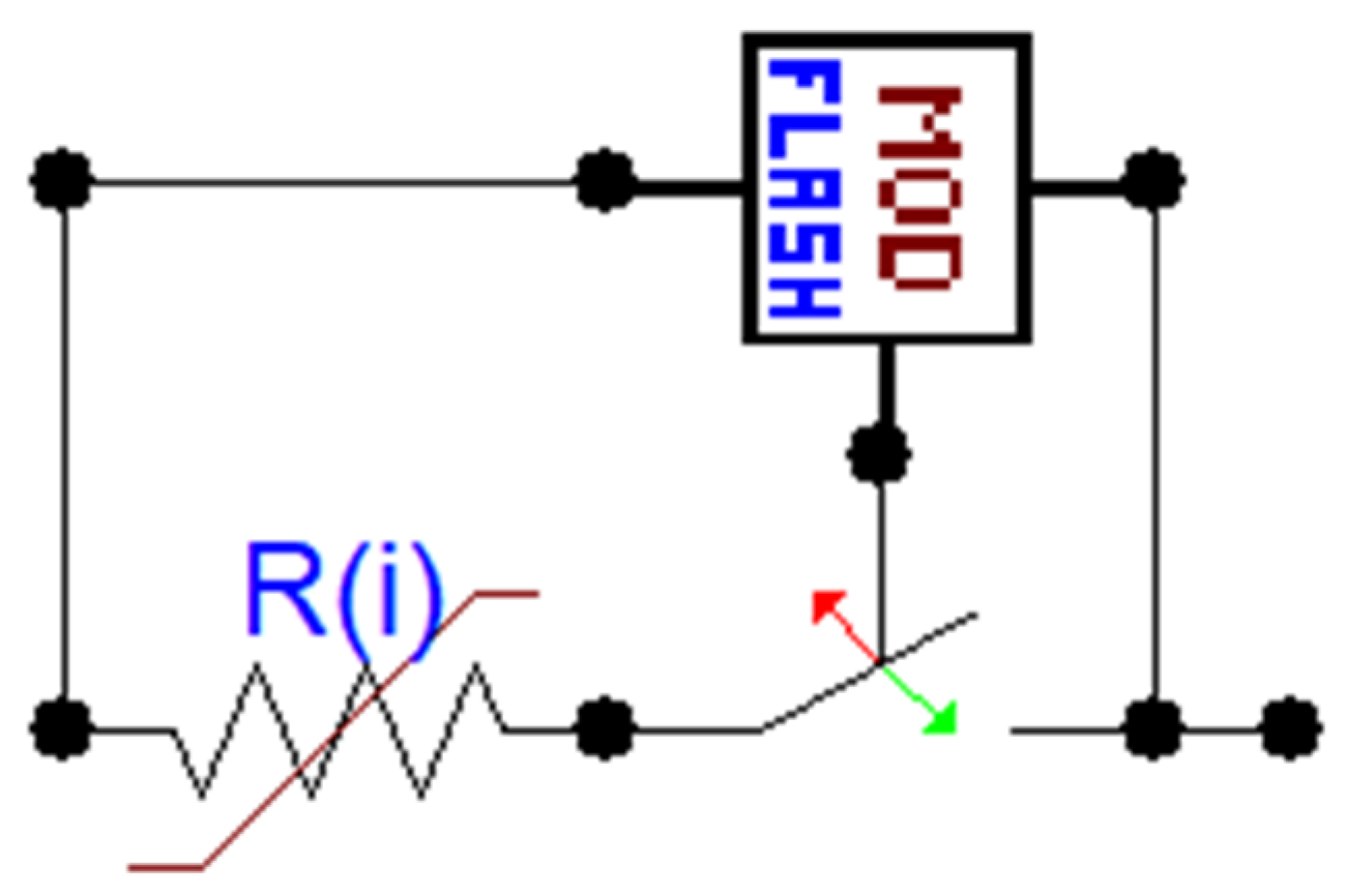
2.5.2. Model Establishment

Anti-thunder and anti-icing composite insulators are composed of an insulation section and a lightning protection section, and its electromagnetic transient model is also composed of two parts. The insulation section provides the insulation function. In this paper, the volt second characteristics of the insulator are used as the breakdown criterion of the insulation section. Breakdown of the air gap is assumed when the overvoltage at both ends of the insulator intersects with the volt second characteristic curve. Established arcing bridges on both sides of the insulation section and applies the overvoltage to the lightning protection section. The lightning protection section is composed of a zinc oxide arrester whose resistance has a good nonlinear characteristic, which means a high resistance when the applied voltage is low, while low resistance when subject to overvoltage. This allows the protection section to behave like an insulator under normal operating conditions but conducts significant transient currents under lightning events. After the overvoltage dies out, high resistance can be recovered to maintain normal operation. A multi-segment exponential function/curve is usually employed to describe the volt–ampere characteristics of the zinc oxide resistor within the surge arrester. Based on its resistance value, the exponential V-I curve is divided into three sections: high resistance section, transition section, and low resistance section. After curve fitting for each section, the V-I characteristics can be expressed as the following function:
{ u = 9185 i 0.05005 ,   10 5 < i < 10 3 A u = 7637 i 0.02335 ,   10 3 < i < 10 3 A u = 2016 i 0.1884 ,   10 3 < i ,
where u is the voltage at both ends of the arrester, in V; i is the amplitude of current conducting through the arrester, in A.
In this paper, the insulator’s volt second characteristic curve is simulated by tailored codes within the commercial software—ATP. The breakdown status of the insulation section is simulated by a controlled switch (ON when the gap breaks down, OFF otherwise). Nonlinear resistance is used for the surge arrester model, in which the volt–ampere characteristics of the zinc oxide resistor are input manually and can be customized. The schematic diagram of the whole model is presented in Figure 3.

3. Analysis of the Factors Affecting the Lightning Withstand Performance after the AACI Insulators Are Installed

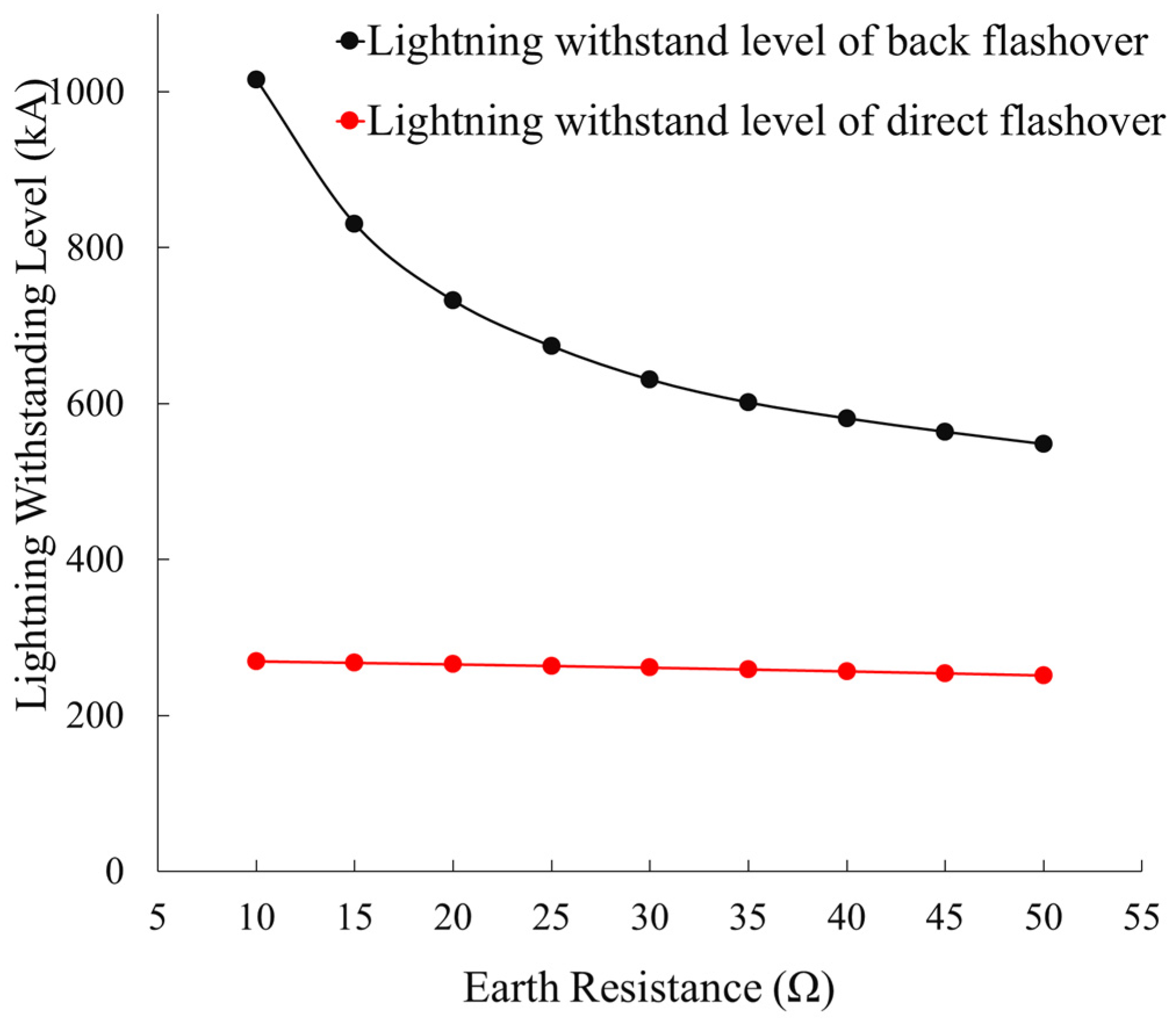
3.1. Influence of the Earth Resistance on Lightning Withstand Level

Since the shield wire was removed from the OHL, the typical lightning strikes will hit the top of the pylon rather than the middle point of the span when the shield wire is presented. Without the shielding effect provided by the shield wire, lightning strikes will hit the HV conductors directly. Within the lightning strike simulation model built using ATP, the lightning current is injected into the highest vertex of the pylon and the center of the span at the highest phase conductor, respectively. These effectively simulate the lightning strike that hits the tower, which causes a flashover between the tower and the phase conductor (known as back flashover) as well as the direct flashover on the phase conductor. The withstand levels are calculated in both cases, and results against earth resistance are shown in Figure 4.
It is observed from Figure 4 that the earth resistance is inversely proportional to the LWL when the ungrounded transmission line is equipped with an AACI. The earth resistance is inversely proportional to the LWL. When the earth resistance increases from 10 Ω to 50 Ω, the LWL decreases from 1015 kA to 548 kA, which reduces the probability of lightning current amplitude close to 0. It is indicated from the analysis that lightning accidents tripping OHLs are unlikely to happen in areas where the soil resistance is high. It is also found that the reduction in LWL is gradually slowed down when earth resistance increases. This is due to two reasons: on the one hand, when the earth resistance increases above a certain value, its impact on the LWL is limited; on the other hand, when a lightning strike hits the tower, although the earth resistance determines the highest voltage potential on the pylon, the existence of the surge arrester is limiting the voltage potential by flashover the air gaps and conducting current through the shunt resistors. This prevented a significant reduction in LWL when earth resistance increased dramatically.
After installing the AACIs, the direct lightning-withstanding level of non-shield-wired OHLs was improved significantly, with an LWL value more than 30 times higher compared to traditional 110 kV lines (7 kA). Moreover, due to the existence of the zinc oxide arrester, the direct lightning-withstanding level does not reduce significantly with the increase in earth resistance. When the earth resistance increased from 10 Ω to 50 Ω, the direct lightning-withstanding level decreased from 269 kA to 251 kA, and the probability of lightning current amplitude fluctuated between 0.1% and 0.2%. This indicates that even if the probability of lightning strikes increases, it is still difficult to cause complete flashover thanks to the AACIs. It can be found that the AACIs effectively improved the direct lightning withstand performance of non-shield-wired OHLs.

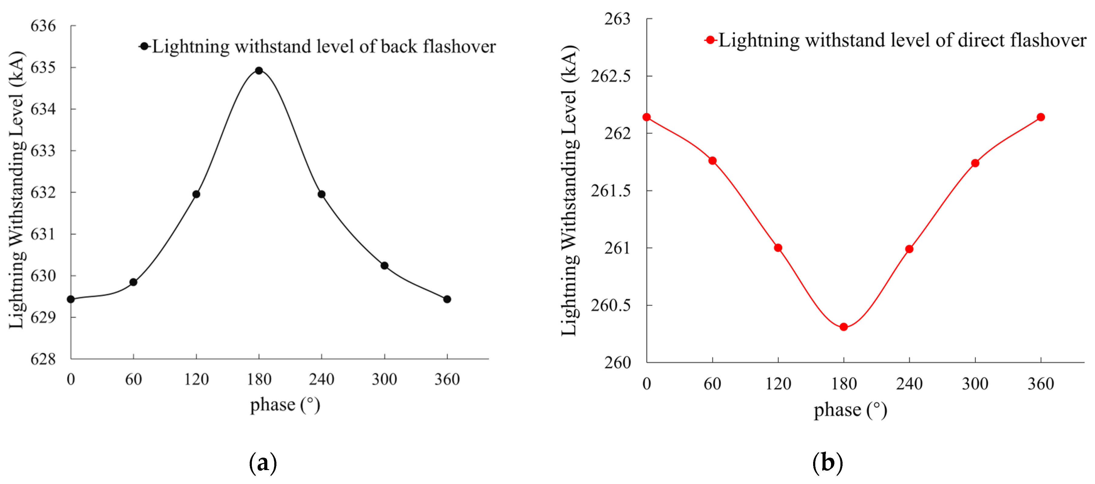
3.2. Influence of the Nominal Voltage Level on Lightning Withstand Level

In order to study the influence of the nominal voltage level on the LWL of non-shield-wired OHLs, this paper added a three-phase nominal voltage source to the lightning strike simulation model. By keeping other simulation parameters the same, the phase angle of the nominal voltage was modified, and its influence on the LWL was analyzed. The calculation results are shown in Figure 5.
It was found that when the phase angle of the nominal voltage varies, the LWL changes as well. However, due to the nonlinear V-I relationship of the surge arrester in the lightning protection section of the AACI, the nominal voltage has little impact on the LWL of the OHL. When a lightning strike hits the pylon, the relationship between the LWL and the phase angle of nominal voltage follows a sine wave. When the phase angle is 0°, the conductor voltage reaches its positive peak value, and this operating voltage is opposite in terms of the polarity to the lightning current, which results in the lowest lightning-withstanding level. When the phase angle is 180°, the conductor voltage reaches its negative peak value, while the operating voltage and lightning current have the same polarity, and the LWL is the highest. When the nominal voltage changes, the maximum and minimum LWLs change by only 0.87%. This is due to the fact that the lightning arrester in the lightning protection section of the AACI has a nonlinear V-I relationship, and the influence of the nominal voltage on the LWL is negligible. It is therefore demonstrated that the AACI can retain its effective protection even when the nominal voltage varies.
When the lightning strikes hit the phase conductors, if the instantaneous voltage on the conductor is positive, it is offset by the negative lightning overvoltage, resulting in a reduced overvoltage seen on the phase conductor, which improves the withstand level for a direct lightning strike. Therefore, when the phase angle is 0°, the instantaneous voltage of the conductor reaches its maximum positive value, where the highest LWL can be achieved. On the contrary, a negative instantaneous voltage on the phase conductor, which is superimposed with the negative lightning overvoltage, worsens its LWL. When the phase angle is 180°, the phase voltage reaches its negative peak, which gives the lowest LWL.

3.3. Influence of Other OHL Parameters on Lightning Withstand Level

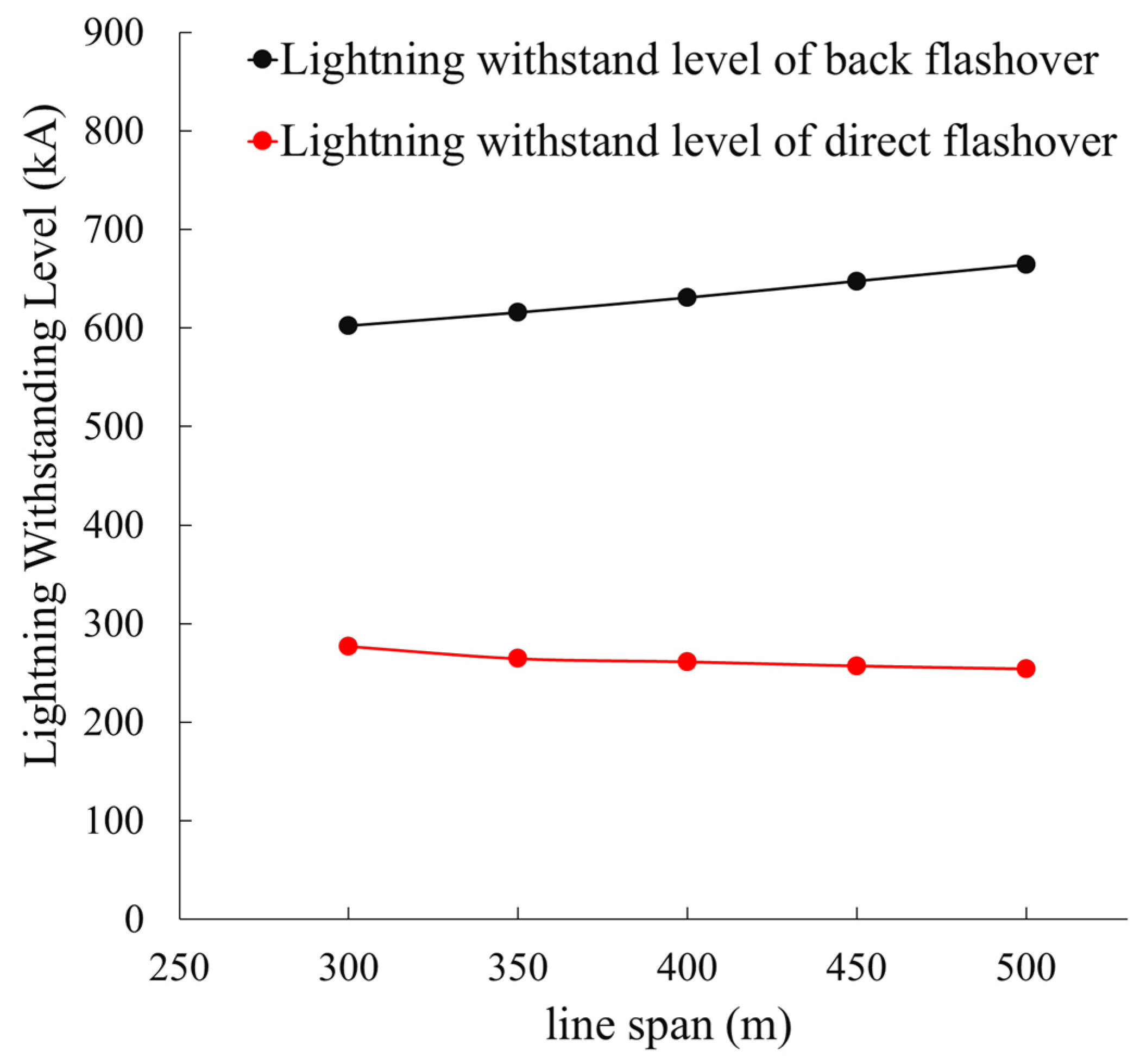
3.3.1. Impact of Span

When lightning strikes hit the pylon of the non-shield-wired OHLs, one clear difference is that the impulse wave does not propagate along the span to the adjacent pylons. The magnitude of the overvoltage, as well as the LWL, is not affected by the length of the span when the insulation section of the AACI did not break down. If the lightning current is large enough to break down the protective gap of the AACI, part of the lightning current flows into the phase conductor span through the lightning protection section, where the span distance starts to affect the LWL. In order to study this impact, all the other parameters are kept constant, while the span distance varies from 300 meters to 500 meters to calculate the LWL of the OHL. The results are shown in Figure 6.
It is found from Figure 6 that the LWL of the back flashover improved with the increased span distance. The LWL of the line increased by approximately 10.2% when the span distance increased from 300 m to 500 m. The reason for this is that after the installation of AACI, the breakdown of the insulation section leads to a portion of the lightning current flowing into the line through the lightning protection section. Increased span distance gave increased impedance, which in the circuit reduces the magnitude of lightning current flowing into the phase conductor and depresses the voltage at both ends of the lightning protection section. The resulting fact that it needs more lightning current to break down the parallel gap of the lightning protection section proved that a longer span distance improved the LWL of non-shield-wired OHLs.
The LWL of non-shield-wired OHLs decreases with the increased span distance. This is because when lightning strikes hit the center of the line span, it is immediately limited by the line impedance. When the span distance increased, the overvoltage induced increased due to the higher impedance, which resulting the lightning current entering the tower through the lightning protection section within this direct-stroke span increasing, resulting in the lightning current flowing into the adjacent span decreasing. It increases the voltage at both ends of the lightning protection section, making it easier for the parallel gap of the lightning protection section to break down, thus reducing the direct lightning-withstanding level of the non-shield-wired OHLs. When the span is increased from 300 m to 500 m, the direct lightning-withstanding level decreases by about 8.1%. It can be found that the non-shield-wired OHLs can always maintain a high LWL when the span distance varies, indicating that the AACI can provide a sufficient level of lightning protection under various span distances and ensure the safe operation of the non-shield-wired OHLs.

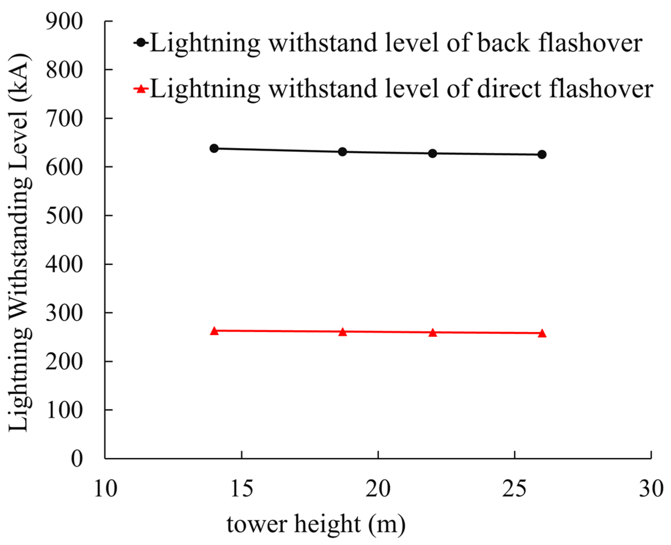
3.3.2. Influence of Tower Raising

The earth resistances and other parameters are assumed to be constant; if we vary the height of the pylon, the impact of it on the LWL of the line is shown in Figure 7.
It is found within Figure 7 that when the tower height increased from 14 m to 26 m, the back flashover and direct lightning-withstanding level of non-shield-wired OHLs decreased from 637 kA to 625 kA and 263 kA to 258 kA, which is a reduction of 1.97% and 1.96%, respectively. It is also found that the tower height has less impact on the LWL of non-shield-wired OHLs. The main reason is that after lightning strikes hit the pylon, although the interval for the reflected waveform to reach the top of the pylon becomes longer, which makes the potential rise on the tip of the pylon, the AACI plays a major clamping role in the non-shield-wired OHLs. Hence, the effect of the tower height on the LWL of the non-shield-wired OHLs is relatively small.

3.4. Analysis of Lightning Strike Tripping Rate after AACI Installed on Non-Shield-Wired OHLs

In order to study the protective effect of AACI on the 110 kV transmission line to the non-shield-wired OHLs, this paper calculates the lightning trip rate and evaluates the lightning risk [27]. According to the research results in the previous section, it is found that the earth resistance has a greater impact on the LWL of the ungrounded transmission line. First, this paper studies the relationship between the earth resistance and the lightning trip rate. The results are shown in Table 1.
It is identified from Table 1 that the earth resistance has a certain degree of impact on the lightning tripping rate of the non-shield-wired OHLs. The total lightning tripping rate increases with the increase in the earth resistance. When the earth resistance increased from 10 Ω to 50 Ω, the total lightning tripping rate increased from 0.017 to 0.022 times/100 km per annual. It is found that even when the earth resistance is relatively high, the lightning trip rate remains low, so very rarely can lighting tripping happen. At the same time, it was found that the lightning trip rate of the traditional 110 kV line is dozens of times higher than the non-shield-wired OHLs with AACI, which proved the fact that the AACI provides excellent lightning protection, especially when used on the non-shield-wired OHLs.
From the lightning risk level perspective, even when the earth resistance is high, the lightning risk of the OHL remains level I, and the lightning risk level is further reduced after the application of the AACI. AACI provides excellent lightning protection by lifting up the lightning-withstanding level of the back flashover and direct flashover. It provides sufficient protection for the 110 kV non-shield-wired OHLs.
It is commonly believed that the higher the pylon’s height is, the larger the lightning initiating area is, and the more lightning strikes would occur, which eventually results in an increase in the lightning tripping rate. Therefore, studying the lightning trip rate under different tower heights is beneficial to further analyze the lightning protection of AACIs. This paper calculates the lightning trip rate under different tower heights. The calculation results are shown in Table 2.
It is observed from Table 2 that the pylon height has a significant impact on the total lightning trip rate of the non-shield-wired OHLs. When the tower height increases from 14 m to 26 m, the lightning tripping rate increases from 0.016 times/100 km per annual to 0.026 times/100 km per annual, an increase of about 62.5%, and the lightning trip rate of the non-shield-wired OHLs is roughly linear with the tower height. Compared with traditional transmission lines, the lightning tripping rate is kept low. Even if the increase in tower heights leads to an increased probability of exposure to lightning strikes, the lightning risk of the OHL has always been at the lowest level I risk, indicating that the AACI still has a good lightning protection effect when the tower height changes, and can effectively shield the 110 kV non-shield-wired OHLs.

4. Influence of AAC Parameters on Lightning Withstand Performance

4.1. Voltage for 50% Probability of Flashover Test for Parallel Protection Gap

The lightning protection section of the AACI is composed of a zinc oxide lightning arrester. The current capacity of its resistor has a certain range, which results in a protection threshold. When the lightning current flowing through the arrester exceeds the protection threshold, it causes damage to the zinc oxide resistor, and the arrester is degraded due to excessive heat from the overcurrent. Therefore, parallel protection gaps are integrated at both ends of the lightning protection section to prevent this. When the residual voltage generated by lightning current conducting through the arrester exceeds its threshold, the parallel protection gap of the lightning protection section is broken down to protect the arrester. In order to study the impact of the parallel protection gap on the LWL and lightning tripping rate of non-shield-wired OHLs, this section described the lightning impulse tests, which varied the distance between two rods. The impact of voltage for a 50% probability of flashover on the rod electrodes with a range of distances is investigated. The relationship curve between voltage for a 50% probability of flashover and protective gap distance is obtained. The parallel protection gap structure installed at both ends of the lightning protection section studied in this paper is shown in Figure 8.
The gap clearance device is composed of a connecting rod and a spherical electrode. The rod-type gap clearance device in Figure 8 is installed at the low-voltage side of the AACI. In order to save space, the rod-type clearance device on the other end is directly connected to the grading ring and installed at the joint of the insulation section and the lightning protection section. The two-rod clearance arrangements together constitute the parallel protective gap of the lightning protection section to provide protection against the zinc oxide resistors.
The rod parallel to the gap in the AACI is made of aluminum alloy. The electrode rod is fixed at the metal end at both sides of the lightning protection section through the clamp plate connector. The length of the rod electrode is 190 mm, and the end is welded with a 50 mm ball head. The rod gap is installed on the insulator according to the selected distance. It is designed to ensure that the upper and lower ends of the installed rod parallel gap are aligned in a straight line. The high-voltage supply from the impulse generator enters the artificial climate chamber through a 330 kV wall bushing and is connected to the high-voltage end of the test object. The other end of the gap device is grounded to conduct the lightning impulse flashover test.
The wavefront/tail time of the lightning impulse wave used in this test is ±1.22/47 µs. According to IEC 60060-1:2010, voltage for a 50% probability of flashover [28] is determined by the lifting and lowering method. The count of the effective test on the rod gap at each spacing arrangement shall not be less than 30.
The characteristics of the parallel protection gap in the lightning protection section (AACI) are investigated. Five typical distances between the upper and lower electrodes of the rod gap structure are selected, 444 mm, 460 mm, 480 mm, 510 mm, and 540 mm, to conduct the tests. The lightning impulse test results of voltage for a 50% probability of flashover on rod gap with various gap distances are shown in Table 1. The deviations of breakdown voltage σ are all within 3%. According to the data presented in Table 3, when the gap distance is 540 mm, the voltage for a 50% probability of flashover of the parallel gap is at its maximum, which is 401.8 kV. When the gap distance is reduced to 444 mm, the parallel gap’s voltage for a 50% probability of flashover drops to 329.9 kV. The smaller the gap distance, the lower the flashover voltage. The lightning impulse 50% discharge voltage of the rod–rod parallel protection gap is in general proportional to the gap distance, which increases with the gap distance.

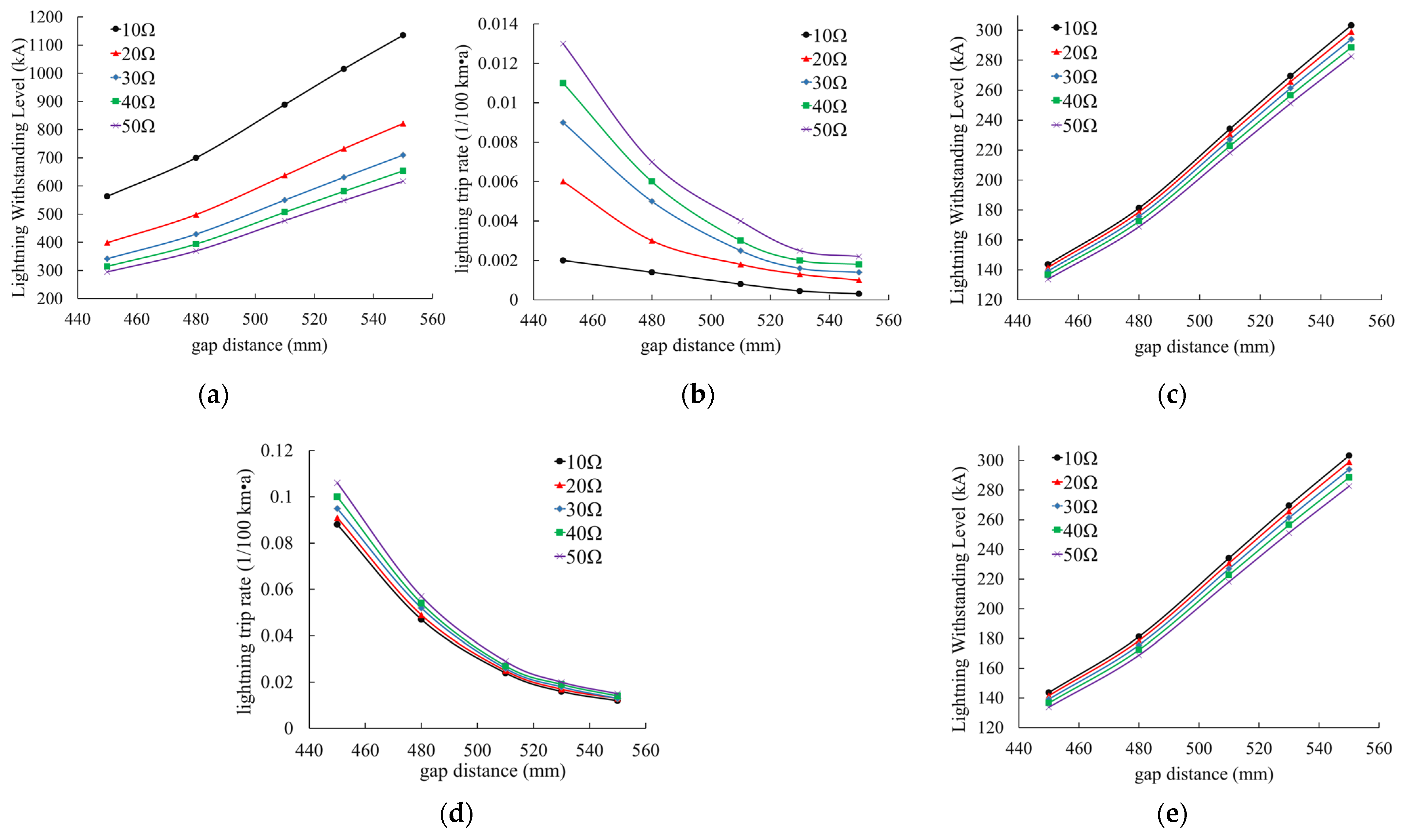
4.2. Analysis of Lightning Tripping Rate of Non-Shield-Wired OHLs with Various Parallel Protection Clearances

The influence of the parallel protection clearance on the OHLs’ lightning protection level after the AACI was installed was studied without considering the shield wire. The gap distance of parallel protection is varied around 530 mm. Selected below the maximum allowed value, the studied clearance distances are 450 mm, 480 mm, 510 mm, 530 mm, and 550 mm. Substitute the fitting curve of lightning impulse flashover voltage and gap distance to obtain the corresponding voltage for a 50% probability of flashover, as shown in Table 4.
According to the analysis, varying the parallel protection gap distance of the lightning protection section will modify the protection range of the zinc oxide resistor and ultimately affect the LWL of the OHLs with the AACI instead of shield wire. In order to obtain the volt second characteristic of composite arrester composite insulator, this paper also carried out a lightning impulse volt second characteristic test, keeping the waveform of impulse voltage unchanged, gradually increasing the voltage amplitude, recording the breakdown voltage U and breakdown time t, obtaining the volt second characteristic data of insulator, and taking it as the breakdown criterion of insulation section, as shown in Table 5. The breakdown voltage of the parallel protection gap of the lightning protection section in the model is varied, while the span distance is fixed to 400 m, and the lightning current waveform is set to 2.6/50 μs. The lightning current was injected into the tip of the pylon at the side of the phase A conductor and the center of the line span to simulate the back flashover on the pylon and direct strike on the lines, respectively. The LWL of the corresponding non-shield-wired OHLs under different parallel protection gap lengths was calculated through simulation. Moreover, the lightning tripping rates for the non-shield-wired OHLs with various gap distances were calculated. The influence of the parallel protection gap of the lightning protection section on the lightning tripping rate is studied. The results are shown in Figure 9.
Due to the increase in parallel clearance distance of the lightning protection section, the LWL of non-shield-wired OHLs increase, while the corresponding back flashover and direct stroke tripping rates decrease. By taking the earth resistance 30 Ω as an example, when the parallel protection gap distance increases from 450 mm to 550 mm, the back flashover tripping rate decreases from 0.009 to 0.001 times/100 km per annual, with a decrease of 88.9%, and the direct trip rate decreases from 0.095 to 0.013 times/100 km per annual, with a decrease of 86.3%, indicating that increasing the parallel gap distance can effectively reduce tripping rates of the back flashover and direct strike on non-shield-wired OHLs.
The lightning tripping rate of non-shield-wired OHLs decreases nonlinearly with the increase in parallel clearance distance. Assuming the earth resistance is 30 Ω, when the distance of the parallel protection gap increases from 450 mm to 550 mm, the lightning trip rate decreases from 0.104 times/100 km per annual to 0.014 times/100 km per annual, with 86.5% reduction, which indicated that increasing the length of parallel protection gap has a significant effect on reducing the lightning trip rate of non-shield-wired OHLs. Therefore, the longer the parallel protection gap of the lightning protection section is, the better the lightning withstand performance of the non-shield-wired OHLs with AACIs. However, attention should also be paid to the aging and degradation of zinc oxide resistors in the lightning protection section. When selecting the gap length, a certain margin should be left. It is a tradeoff to select the optimized parallel protection gap length of the lightning protection section.

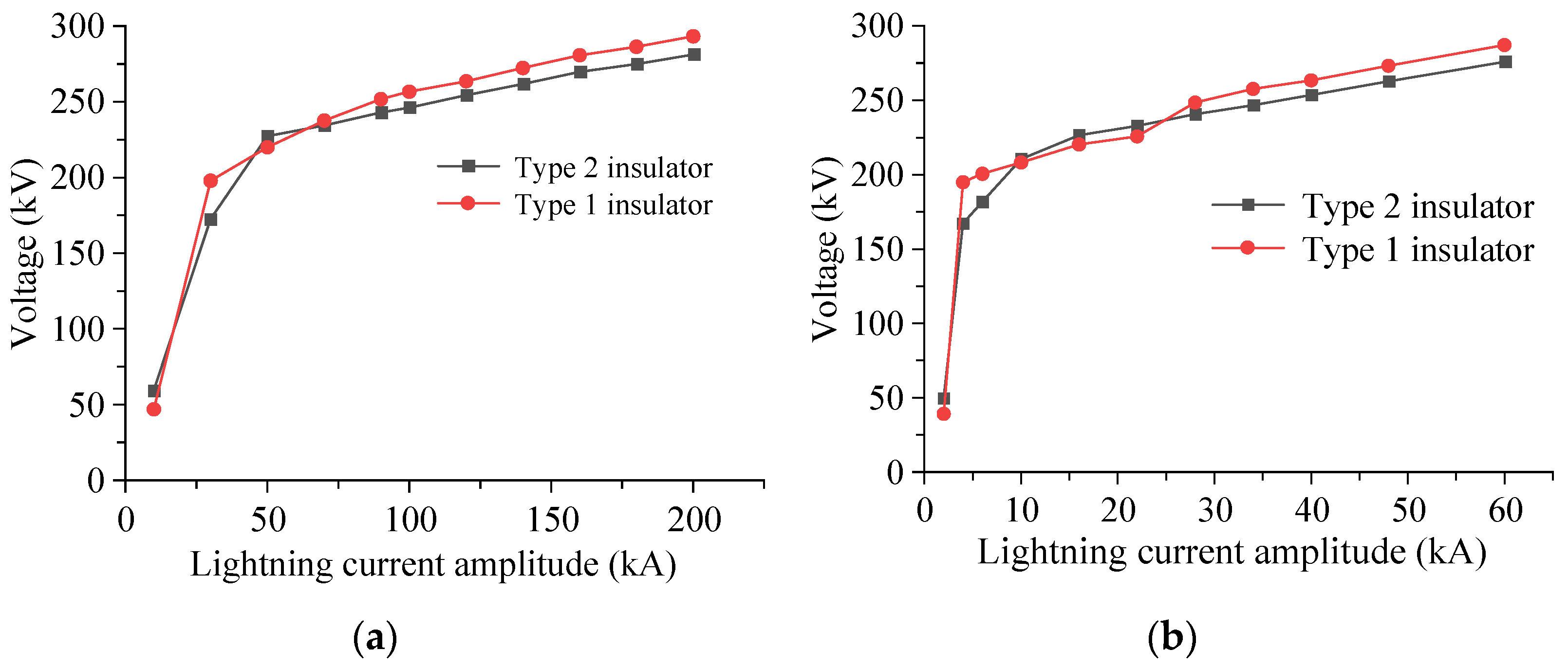
4.3. Analysis of the Influence of the Volt–Ampere Characteristic of the Arrester on Lightning Withstand Performance of the Non-Shield-Wired OHLs

The AACI mentioned in the previous section is classified as the Type 1 insulator; the other type of AACI, which improved the volt–ampere characteristics of zinc oxide resistor, is known as the Type 2 insulator. In addition to the different volt–ampere characteristics of zinc oxide resistors, the two types of insulators have the same insulator length, a distance of parallel clearance, arrangement of sheds, etc. Based on the established simulation model of non-shield-wired OHLs, the volt–ampere characteristic data in the model was customized to perform the study. It stimulates the lightning-withstanding performance of the two types of insulators, respectively. In the case of lightning strikes hitting towers and lines, the calculation results of overvoltage at both sides of the lightning protection section are shown in Figure 10.
From the above, it can be seen that the overvoltage characteristics of the lightning protection section of the two types of insulators are different when lightning strikes hit the tip of the pylon. When the amplitude of the lightning current is low, the voltage of Type 1 and Type 2 insulators has no fixed trend, and their overvoltage curves are crossed. When the lightning current amplitude gradually increases to a certain level, the voltage at both sides of the lightning protection section of the Type 2 insulator becomes less than the Type 1 insulator. The difference between them almost remains constant with the increase in lightning current. When lightning strikes hit the line, the distribution law of overvoltage at the lightning protection section of the two types of insulators is generally similar to that of lightning strikes that hit the tower directly. When the lightning current amplitude increases to a certain level, the voltage at the lightning protection section of the Type 2 insulator is less than that of the Type 1 insulator. The zinc oxide resistor of the Type 2 insulator performs better than the Type 1 insulator in limiting lightning overvoltage, which indicates that the Type 2 insulator has a better lightning protection effect when the lightning current amplitude is high.
In order to better analyze the difference in lightning protection effects of two types of AACIs on non-shield-wired OHLs, this paper calculated the lightning trip rate of non-shield-wired OHLs with Type 2 insulators. The calculation results are shown in Table 6.
According to the calculation results, changing the volt–ampere characteristics of the zinc oxide resistor can modify the LWL of the OHLs using AACIs to replace their shield wires. When the earth resistance varied, the LWL of the non-shield-wired OHLs with the Type 2 insulator is higher than that of the Type 1 insulator, which indicates that the LWL of the non-shield-wired OHLs can be improved by optimizing the zinc oxide resistor. Due to the improvement of the LWL of the line, the back flashover tripping rate and the direct strike tripping rate are both reduced. Through comparative analysis of the total lightning tripping rate of non-shield-wired OHLs, the lightning tripping rate corresponding to Type 2 insulators is about 8% lower than Type 1 insulators, so Type 2 insulators have a better lightning protection performance than Type 1 insulators. They can better protect non-shield-wired OHLs in future applications.

5. Conclusions

This paper presented studies on the lightning withstand performance of the AACI on a 110 kV OHL after its shield wire had been removed. Simulation models are established to study the impact of various factors, such as the grounding impedance, nominal voltage, overhead line span, pylon height, etc., on the lightning protection performance after the AACI was deployed. Impulse tests were conducted to examine the influence of the design parameters of AACI on its lightning protection performance. The conclusions are summarized as follows:
  • The earth resistance, nominal voltage, span, and height of the pylon all affect the AACI’s LWL after the shield wires are abandoned, among which earth resistance has the greatest influence. When the earth resistance increases from 10 Ω to 50 Ω, the withstand level of lightning against back flashover and direct flashover decreased by 46% and 6.7%, respectively. In contrast to this, the influence of nominal voltage is relatively minor on its LWL. When the phase angle of nominal voltage changes, the LWL of back flashover and direct flashover only varied by 0.87% and 0.7%, respectively. Increased span distance results in an increased LWL on the back flashover but decreased withstand level on the direct flashover. The influence of the height of the pylon on the LWL is relatively negligible. When the height of the pylon increased from 14 m to 26 m, the LWL in a back flashover and direct strike decreased by 1.97% and 1.96%, respectively.
  • The LWL of a transmission line can be effectively improved through the installation of AACIs after the shield wire is removed. Assuming the tower earth resistance is 30 Ω, the LWL of the back flashover and direct flashover are 630.88 kA and 261.33 kA, respectively. The corresponding probabilities of the withstand lightning currents are 0.015% and 0.161%, respectively, for back flashover and direct flashover. The shielding failure rates are controlled at a low level by the AACI.
  • The LWL of the non-shield-wired OHLs increases with the parallel clearance on the lightning protection section. By taking the earth resistance of 30 Ω as a benchmark, when the length of the parallel protective gap increases from 450 mm to 550 mm, the lightning shielding failure rate decreases by 86.5%. It is also found that changing the volt–ampere characteristic of the zinc oxide resistor can reduce the lightning shielding failure rate by approximately 8% compared to the original design.

Author Contributions

Author Contributions: Formal analysis, J.H. (Jianping Hu) and Z.F.; Methodology, J.H. (Jianping Hu), T.Z., and J.H. (Jianlin Hu) and Z.F.; data curation, J.H. (Jianping Hu), Z.F., and R.Z.; Supervision, J.H. (Jianlin Hu), Z.F., and R.Z.; Writing—original draft, T.Z. and R.Z. Writing—review and editing, J.H. (Jianping Hu), T.Z., and J.H. (Jianlin Hu). All authors have read and agreed to the published version of the manuscript.

Funding

This research is supported by the Science and Technology Project of State Grid Corporation of China (5216A020005F).

Data Availability Statement

The data presented in this study are available on request from the corresponding author.

Acknowledgments

The authors are grateful to the Science and Technology Project of State Grid Corporation of China (5216A020005F).

Conflicts of Interest

The authors declare no conflict of interest.

References

  1. Huo, Z.; Li, C.; Kong, R. Review on Disaster of Wire Icing in China. J. Appl. Meteorol. Sci. 2021, 32, 513–529. [Google Scholar]
  2. Bian, L. Study on Prediction and Control of Icing Risk in Power Engineering Line Design. Master Thesis, North China Electric Power University, Beijing, China, 2020. [Google Scholar]
  3. Jiang, X.; Bi, M.; Li, Z.; Xiang, Z.; Dong, B.; Zhao, S. Study on DC Ice Melting and Ice Shedding Process Under Natural Condition. Power Syst. Technol. 2013, 37, 2626–2631. [Google Scholar]
  4. Ruan, Q.Y.; Gu, X.P.; Lu, J.Z.; Zhang, H.X. Study on problem of DC ice-melting of the Hunan 220 kV power grid. Power Syst. Prot. Control 2011, 39, 131–136. [Google Scholar]
  5. Fu, C.; Rao, H.; Li, X.; Chao, J.; Tian, J.; Chen, S.; Zhao, L.; Xu, S.; Ma, X. Development and Application of DC Ice Melting Device. Autom. Electr. Power Syst. 2009, 33, 53–56, 107. [Google Scholar]
  6. Gong, Y.; Wang, Y.; Fan, S.; Lei, Z. Analysis of Maximum Allowable Lightning Current on Lanpu No.1 Line When Canceling Earth Line. Environ. Technol. 2016, 34, 36–38. [Google Scholar]
  7. Zou, J.; Zhng, Y.; Hu, J.; Zhang, D.; Zhou, L. Selection of Lightning Surge Arrester in the Event of Removing Ground Wires From Iced Transmission Line. Insul. Surge Arresters 2022, 3, 26–31, 41. [Google Scholar]
  8. Lu, J.; Xie, P.; Hu, J.; Fang, Z.; Wu, W.; Jiang, Z. Transmission Line without Lightning Conductor. CN 111431129 A, 17 July 2020. [Google Scholar]
  9. Hu, J.; Zhang, R.; Zhen, F.; Wang, X.; Sun, K.; Jiang, X. Analysis of lightning protection performance of 110 kV transmission line canceling lightning wire. In Proceedings of the 22nd International Symposium on High Voltage Engineering, Xi’an, China, 21–26 November 2021. [Google Scholar]
  10. Hayashi, T.; Mizuno, Y.; Naito, K. Study on transmission-line arresters for tower with high footing resistance. IEEE Trans. Power Deliv. 2008, 23, 2456–2460. [Google Scholar] [CrossRef]
  11. Podporkin, G.V.; En’Kin, E.Y.; Pil’Shchikov, V.E. The development of multichamber arresters. Russ. Electr. Eng. 2013, 84, 1–5. [Google Scholar] [CrossRef]
  12. de Vasconcellos, F.; Alípio, R.; Moreira, F. Evaluation of the Lightning Performance of Transmission Lines Partially Protected by Surge Arresters Considering the Frequency-Dependent Behavior of Grounding. IEEE Lat. Am. Trans. 2022, 20, 352–360. [Google Scholar] [CrossRef]
  13. Liao, W.; Liu, X.; Lei, X.; Liu, Q.; Zeng, H.; Cui, T. Research on Lightning Protection of Transmission Line in High Soil Resistivity Section Based on Line Arrester. Insul. Surge Arresters 2020, 5, 84–90. [Google Scholar]
  14. Li, W.; Yang, W.; Li, C. Performance Impact of Impulse Characteristics of Grounding System on Transmission Line Arresters. Insul. Surge Arresters 2019, 1, 189–194. [Google Scholar]
  15. Wang, Z.; Song, M.; Bo, Y.; Yang, T.; Su, S. Quantitative comparison of lightning protection effect between 35 kV line arrester and lightning line. J. Electr. Power Sci. Technol. 2021, 36, 165–171. [Google Scholar]
  16. Jiang, Z.; Wu, W.; Wang, B. 500 kV Line Lightning Protection and Ice Flashover Composite Insulator. CN 109786046 A, 27 August 2019. [Google Scholar]
  17. Wang, B.; Jiang, Z.; Lu, J.; Hu, J.; Wu, W. Simulation Study of Lightning Protection Performance of 500 kV Anti-Icing and Anti-Thunder Composite Insulator. Power Syst. Technol. 2017, 41, 2393–2401. [Google Scholar]
  18. Wu, W.; Jiang, Z.; Lu, J.; Fang, Z.; Hu, J.; Wang, B. Structure Design and Electric Field Simulation Research on 500 kV Anti⁃icing Flash Insulator with Lightning Protection Function. High Volt. Appar. 2018, 54, 9–15. [Google Scholar]
  19. Hu, J.; Zhou, H.; Fang, Z.; Liu, W.; Xie, P. Development and Tests of a 220 kV Novel Composite Insulator with Lightning Protection and Icing Flashover Prevention. In Proceedings of the 2019 IEEE 3rd Conference on Energy Internet and Energy System Integration (EI2), Changsha, China, 10 November 2019; pp. 2418–2423. [Google Scholar] [CrossRef]
  20. Lu, J.; Zhao, C.; Jiang, Z.; Xie, P.; Hu, J. Simulation and experiment of a composite insulator with lightning protection and icing flashover prevention. In Proceedings of the 2014 International Conference on Lightning Protection (ICLP), Shanghai, China, 11–18 October 2014; pp. 1987–1991. [Google Scholar] [CrossRef]
  21. Abur, A.; Ozgun, O.; Magnago, F.H. Accurate modeling and simulation of transmission line transients using frequency dependent modal transformations. In Proceedings of the 2001 IEEE Power Engineering Society Winter Meeting Conference Proceedings, Columbus, OH, USA, 28 January–1 February 2001; Volume 3, pp. 1443–1448. [Google Scholar]
  22. Zeng, C.; Zhou, Y.; Zhou, Y.; Zhou, K.; Peng, Z. Research on Lightning Protection Performance for Hybrid Transmission Lines. High Volt. Appar. 2021, 57, 131–137. [Google Scholar]
  23. Chen, P.F.; Zhou, Y.S.; Ge, T.K.; Xiong, Q.; Yuan, X.L.; Zhang, Y. The Analysis on Lightning Withstand Performance of AC/DC MultiCircuit Transmission Lines on Same Tower Based on ATP—EMTP. Insul. Surge Arresters 2019, 3, 111–117. [Google Scholar]
  24. Morales, J.A.; Orduna, E.A.; Cabral, R.J.; Bretas, A.S. Combined TACS-MODELS for Footing Tower Resistance considering ground ionization. In Proceedings of the 2014 North American Power Symposium, Pullman, WA, USA, 7–9 September 2014. [Google Scholar]
  25. Yang, Q.; Zhao, J.; Sima, W.; Feng, J.; Yuan, T. Lightning Back Flashover Performance of the Yun_Guang UHVDC Transmission Lines. High Volt. Eng. 2008, 34, 1330–1335. [Google Scholar]
  26. Yamanaka, A.; Nagaoka, N.; Baba, Y. Circuit Model of Vertical Double-Circuit Transmission Tower and Line for Lightning Surge Analysis Considering TEM-mode Formation. IEEE Trans. Power Deliv. 2020, 35, 2471–2480. [Google Scholar] [CrossRef]
  27. QGDW11452—2015; Guide for Lightning Protection of Overhead Transmission Lines. STATE GRID Corporation of China: Beijing, China, 2016.
  28. IEC 60060-1-2010; High Voltage Test Techniques-Part 1: General Definitions and Testrequirements. Standards Press of China: Beijing, China, 2005.
Figure 1. Multi-wave impedance model.
Energies 16 00815 g001
Figure 2. Structure diagram of anti-thunder and anti-icing composite insulator.
Energies 16 00815 g002
Figure 3. Composite surge arrester model.
Energies 16 00815 g003
Figure 4. Influence of earth resistance on LWL.
Energies 16 00815 g004
Figure 5. Influence of phase on LWL: (a) LWL of back flashover; (b) LWL of direct flashover.
Energies 16 00815 g005
Figure 6. Influence of line span on LWL.
Energies 16 00815 g006
Figure 7. Influence of tower height on LWL.
Energies 16 00815 g007
Figure 8. Ring parallel gap of insulator.
Energies 16 00815 g008
Figure 9. Lightning protection performance under different gap distances: (a) trend chart of back flashover LWL; (b) trend chart of back flashover lightning trip rate; (c) trend chart of direct LWL; (d) trend chart of direct lightning trip rate; (e) trend chart of direct lightning trip rate.
Energies 16 00815 g009
Figure 10. Influence of lightning current amplitude on voltage: (a) overvoltage of back flashover; (b) overvoltage of direct flashover.
Energies 16 00815 g010
Table 1. Lightning trip rate of the line no ground wire under the earth resistance changes.
Earth Resistance (Ω)Back Flashover Trip Rate
(1/100 km·a)
Direct Flashover Trip Rate
(1/100 km·a)
Lightning Trip Rate
(1/100 km·a)
Assessment of Lightning Risk
100.0000.0170.017I
150.0010.0170.018I
200.0010.0170.018I
250.0010.0170.018I
300.0020.0180.020I
350.0020.0180.020I
400.0020.0190.021I
450.0020.0190.021I
500.0020.0200.022I
Table 2. Lightning trip rate of the line under the tower height changes.
Tower Height (m)Back Flashover Trip Rate
(1/100 km·a)
Direct Flashover Trip Rate
(1/100 km·a)
Lightning Trip Rate
(1/100 km·a)
Assessment of Lightning Risk
140.0010.0150.016I
18.70.0020.0180.020I
220.0020.0200.022I
260.0020.0230.026I
Table 3. The 50% lightning impulse flashover voltage of parallel gap.
Gap Distance (mm)50% Flashover Voltage (kV)Relative Standard Deviation
444329.90.017
460341.50.019
480356.40.023
510370.40.021
540401.80.028
Table 4. The voltage for 50% probability of flashover of parallel gap.
Gap Distance (mm)Voltage for 50% Probability of Flashover (kV)
450333.95
480355.29
510376.64
530390.87
550405.10
Table 5. The volt second characteristic of lightning impulse.
The Group NumberWave Front (μs)Wave Tail (μs)Impulse Voltage (kV)Whether It Is Broken Down
11.22717.16448.45
21.22717.3461.16
31.2110.24473.77
41.197.67487
51.27.43501.64
61.226.69514.61
71.26.45527.71
81.215.66538.63
91.234.92555.63
101.24.22563.82
111.23.99577.59
121.213.65591.20
131.223.55604.97
141.213.48616.76
151.23.6629.12
161.223.41616.79
171.223.5604.04
181.214.08591.01
191.244.13583.85
201.24.84568.04
Table 6. Lightning trip rate under different earth resistance of Type2 insulator.
Earth Resistance (Ω)* I1 (kA)n1 (1/100 km·a)I2 (kA)n2 (1/100 km·a)N (1/100 km·a)
101046.460.000277.510.0150.015
15854.660.001275.510.0160.017
20754.050.001273.440.0160.017
25695.890.001271.270.0160.017
30651.410.002268.980.0170.019
35623.550.002266.540.0170.019
40601.010.002263.990.0170.019
45581.190.002261.270.0180.020
50566.700.002258.320.0180.020
* I1 refers to the back flashover lightning-withstanding level. n1 refers to the back flashover trip rate. I2 refers to the direct flashover lightning-withstanding level. n2 refers to the direct flashover trip rate. n refers to the striking lightning trip rate.
Disclaimer/Publisher’s Note: The statements, opinions and data contained in all publications are solely those of the individual author(s) and contributor(s) and not of MDPI and/or the editor(s). MDPI and/or the editor(s) disclaim responsibility for any injury to people or property resulting from any ideas, methods, instructions or products referred to in the content.

