
Micro Gas Turbine Role in Distributed Generation with Renewable Energy Sources

Department of Industrial Engineering, University of Naples Federico II, Via Claudio 21, 80125 Naples, Italy
Energies 2023, 16(2), 704; https://doi.org/10.3390/en16020704
Submission received: 7 December 2022
/
Revised: 27 December 2022
/
Accepted: 4 January 2023
/
Published: 7 January 2023
(This article belongs to the Special Issue Computational and Data-Driven Modeling of Combustion in Reciprocating Engines or Gas Turbines)
Abstract
:To become sustainable, the production of electricity has been oriented towards the adoption of local and renewable sources. Distributed electric and thermal energy generation is more suitable to avoid any possible waste, and the Micro Gas Turbine (MGT) can play a key role in this scenario. Due to the intrinsic properties and the high flexibility of operation of this energy conversion system, the exploitation of alternative fuels and the integration of the MGT itself with other energy conversion systems (solar field, ORC, fuel cells) represent one of the most effective strategies to achieve higher conversion efficiencies and to reduce emissions from power systems. The present work aims to review the results obtained by the researchers in the last years. The different technologies are analyzed in detail, both separately and under a more complete view, considering two or more solutions embedded in micro-grid configurations.
1. Introduction
The awareness of the environmental and climatic damage caused by decades of excessive energy consumption with the use of fossil fuels has been achieved. Following the well-known international treaties [1], there are currently many countries involved in formulating strategies to control fuel consumption and pollution emissions, to limit the anthropogenic impact [2].
To obtain a sustainable production of electricity, research has been oriented towards the adoption of renewable local resources such as biomass, solid residues from various industrial processes, or towards the use of hydrogen. To this end, the Micro Gas Turbine (MGT) can significantly contribute to a more flexible employment and efficient conversion of energetic sources [3,4,5]. Even if simple cycle MGTs feature lower efficiency levels with respect to reciprocating internal combustion engines (ICE), modifications can be made to the plant architecture to overcome this issue [6], such as regeneration, post-combustion, vapour injection and air humidification [7], and the gap between these two technologies can be reduced by the implementation of advanced materials [8] or even by using different working media (air, nitrogen, hydrogen, helium, xenon and carbon dioxide) [9].
With the main purpose is to reduce emissions and to better control the reaction zone, improvements can still be made especially on the combustor design through additive manufacturing [4] and the external combustion-air adjustment [10]. In addition, a proper modeling of the complex dynamic characteristics of micro gas turbine components allows for the identification of the lower fuel consumption areas, including those during the start-up process [3,11]. Moreover, it is well-known that gas turbines are supplied with a substantial excess of air, and in general produce high emissions of nitrogen oxides (NOx). To overcome this issue, innovative combustor concepts were implemented to limit the formation of pollutants such as the Dry Low NOx (DLN) or the Rich-Burn, Quick-Mix, Lean Burn (RQL). Unfortunately, MGTs are not a simple scale down of standard gas turbines and, due to the required reduced dimensions and reduced costs, such complex combustors cannot always be adopted, or at least they must be redesigned for turbines with a different architecture like MGT. However, an applicable solution to MGTs is also represented by the exhaust gas recirculation (EGR). Indeed, it is experimentally observed that EGR has a positive influence on the heat release rate, reducing the non-uniformities in temperature distribution [12]. EGR used in humified air turbines (HAT) increases CO2 partial pressure, thereby leading to a more efficient post-combustion capture [13]. Alternatively, CO2 concentrations in the exhausts could be enhanced by employing a selective exhaust recirculation By using a CO2-selective system, it is possible to separate CO2 from the flue gas and recirculate it back to the inlet of the compressor. In this way, a saving in economics and energy for the downstream CO2 capture plant can be attained as well [14].
Nevertheless, the addition of carbon capture and storage (CCS) systems complicates the plant that on the contrary is required to be compact and not-excessively expensive. Therefore, considering that an acceptable level of the thermal efficiency can be achieved only with regeneration, and that the maximum value cannot be reached at maximum power output [15], the economic success of micro gas turbine applications strongly depends on the optimal usage of the system with a proper compromise on greenhouse gas emissions. Indeed, the main efforts are addressed to a full exploitation of the fuel, obtained by embedding heat recovery in the overall setup, that is, with a combined heat and power plant (CHP) [16]. In this regard, vapour injection and HAT cycle was evidenced to further increase the flexibility of an MGT plant, to enhance the heat capacity of the mixture entering the combustor, to lower fuel consumption and a more efficient recovery of heat in the recuperator [17,18].
The current trend is to create small-scale plants with the aim of exploiting alternative sources and recovering waste energy, which means moving towards a decentralized production with micro-grids capable of self-producing electric and thermal energy, and at the same time, are connected directly to the distribution network, with reduced transmission losses (grid-connect) or, in some cases, are totally consumed by the self-producer (stand-alone) [19]. The electrical grids are, therefore, required to function as bidirectional systems, managing to accommodate the energy production coming from multiple generation nodes. Through distributed generation, electricity is then produced directly on the site. It is, therefore, a decentralized production with a power rating of 25–500 kW, suitable for small- and medium-sized companies [20] and residential utilities [21].
Despite lower efficiency and higher prices compared to ICE, MGT offers major potential advantages in small-scale power generation. For instance, a compact size, a low weight per unit power, a small number of moving parts, lower noise, multi-fuel capabilities and opportunities for lower emissions due to the high-quality recoverable heat at the turbine exhaust [16]. This last characteristic makes the MGT implementation feasible not only for the combined production of heat and power [22] but with the addition of an absorption chiller, cooling generation (CCHP) is possible as well [23].
In the last several years, many manufacturers have proposed some packaged micro-gas turbines with the benefit of lower maintenance costs and high availability. The main application for micro-gas turbines is in packaged small-scale CHP which can be installed as single or multiple units. Typical performance features of the main MGTs used are summarized in Table 1.
In the last column for each MGT the emissions of CO2 in gram per unit of electric energy produced are calculated considering pure CH4 as fuel with a LHV of 50 MJ/kg in a stoichiometric reaction:
Table 1 highlights that, if only the electric production is accounted for, the emissions of CO2 are unacceptable in today’s climate where environmental sustainability requires that greenhouse emissions are reduced. Conversely, a significant exhaust heat recovery to produce additional power, heat or cooling increases the total efficiency (or the fuel utilization factor), thus allowing a substantial savings in fuel and a reduction in CO2.
Moreover, a further reduction in emissions can be obtained from the already mentioned high flexibility operation of MGTs [31,32,33]. Indeed, apart from the most used natural gas (NG), they can be supplied with carbon-neutral fuels such as synthetic gases obtained from the processing of biomass feedstocks. However, due to the different chemical compositions and the lower energetic contents, a deep analysis of the system behaviour when using these fuels is mandatory [34,35,36]. Furthermore, the increasing interest towards hydrogen derives not only from the absence of carbon but also from the beneficial effects on performance and flame stabilization that are induced by a moderate presence of this species in the syngas [37], whereas the well-known problem of flashback at higher hydrogen concentrations can be easily prevented by using water dilution [38].
Finally, micro gas turbines are well suited to be coupled with power and heat generation systems supplied with renewable medium-temperature energy sources. Indeed, the integration of MGT with biomass gasification, solar fields, Organic Rankine Cycle (ORC) units and Fuel Cell (FC) allows for the building of self-sustaining plants, the so-called “micro-grid”, that is able to support the distributed generation of heat and power, even in isolated areas with a consistent fuel saving. As a matter of fact, it should be emphasized that the evolution of small-size gas turbines, together with the use of renewable sources, are in favor of distributed energy in micro-grid configurations, which is capable of satisfying the needs of autonomous electricity supply and heat in an environmentally friendly manner. To this end, several studies are focused on improving and optimizing MGT-based systems and verifying the plant’s economic feasibility [16,39,40].
In this review, an investigation on different plant layouts integrating the MGT with several renewable energy sources that stand out with regard to optimal energetic performance and low ambient impact is presented. An attempt is made to classify innovative elements by typology on an MGT plant that could be integrated into a micro-grid. However, a clear division between these types of hybrid systems is not always possible since there is often an overlap of such elements, complicating the installation but increasing the efficiency and reducing the environmental impact.
The work is organized as follows. In Section 2, the utilization of alternative fuel in a micro gas turbine is examined in terms of combustion stability, performance, and emission; then different hybrid systems in which the MGT is integrated are described. Section 3 focuses on solar fields, Section 4 on ORC while fuel cells are illustrated in Section 5. Finally, some hints regarding the application of MGTs in transport sector are provided in Section 6.
2. Alternative Fuels in Micro Gas Turbines
MGT represents a viable solution to the progressive increase in natural gas costs and the necessity of reducing greenhouse gas emissions. Indeed, it can be supplied with alternative liquids (kerosene and diesel) and gaseous fuels (syngas and hydrogen). Moreover, the use of fuels obtained from biomass, although usually characterized by a higher price than natural gas, guarantees the same production of dispatchable electricity while maintaining net zero carbon emissions.
2.1. Syngas
Directive 2001/77/EC defines as biomass “the biodegradable fraction of products, waste and residues from agriculture (including vegetal and animal substances), forestry and related industries, as well as the biodegradable fraction of industrial and municipal waste” [41]. It is considered a renewable energy source that is respectful of the environment because it is “carbon-neutral”. According to the Intergovernmental Panel on Climate Change (IPCC), carbon neutrality is obtained when anthropogenic emissions of greenhouse gases are compensated by an equal number of emissions reduced, avoided, or sequestered within a certain time frame [42]. Basically, the CO2 released by the energy processes of biomass would be the same as that biologically released in nature during its “life cycle”.
The different pathways for producing energy from biomass often lead to an intermediate product such as synthesis gas (or syngas) and biofuels, which are typically rich in hydrogen and carbon monoxide. However, depending on the original feedstock and process (pyrolysis, anaerobic, gasification, partial oxidation, just to name a few), chemical and physical properties of the final fuel can be very diverse. Consequently, combustion stability, temperature, efficiency, and emissions are strongly affected by the composition as well. Although these conversion processes are optimized [43], usually these kinds of fuels are characterized by a reduced lower heating value (LHV) with respect to natural gas. The latter aspect must be accounted for especially when syngas feeds a MGT designed to work with NG. Indeed, to maintain a constant energy supply, the reduced LHV imposes an enhancement of fuel mass flow and thus leading the turbine and the compressor to part load-like conditions. This means that not only the combustion itself, but the whole system’s efficiency is affected by varying fuel characteristics.
Delattin et al. [34] discussed the experimental and imaging results found for a combustor burning NG, syngas (from a steel mill) or a mixture of both. It was found that the beneficial effects from the presence of H2 and CO are surpassed by the negative influence of water, and differences were noted in terms of flame shape, flame temperature and anchored position. Near walls temperature remained within the allowable limits, avoiding problems with material resistance for hydrogen-rich mixtures as well. The location of the flame tended to move towards the pilot cup causing flashback phenomena. However, no problems concerning blowoff, dynamic instability or auto-ignition were detected. Also, at equal thermal loads, the combustion of the syngas produced remarkably low NOx and CO emissions.
To overcome the limitations of syngas supply in [44] the FLOX-combustion system was tested in the Turbec T100 micro turbine. Such a combustion system is based on the flameless oxidation (FLOX) concept. Similar to the original combustion system of the T100, the fuel was distributed through two lines: pilot and main stages. However, due to the higher fuel mass flow rate required, bigger valves were installed in the test rig and an additional adjustable nozzle ensured a constant pilot fuel mass flow, used for ignition and flame stabilization. Instead, the main stage presented ten annular air nozzles with coaxial fuel jets. The high momentum generated by the injected jets created a wide central recirculation zone towards the exit of the jets, allowing a strong mixing of air and exhaust gases before the reaction zone. In turn, the jets of the main stage entrained the hot gases from the pilot stage, that, in this way, assisted the combustion inside the main region. This combustion system ensured a stable operation between 50 and 100 kWel while enabling a reliable start-up procedure of the micro turbine supplied with a 5.0 MJ/kg LHV fuel. Moreover, the pressure losses across the combustor remained below 4% but, most importantly, the emissions of CO and NOx were less than 30 ppm and 6 ppm, respectively. Another flameless combustion concept that is attracting the interest of researchers is the Moderate and Intense Low-Oxygen Dilution (MILD) combustion since it proved to enhance efficiency and decrease emissions. To establish the MILD regime, strong exhaust gas recirculation is required to abate oxygen reactivity. Additionally, in this case, this is obtained via a proper geometry of the burner and the design of the gas inlet nozzles. Fortunato et al. [45] discussed the performances of the combustion chamber (CC) when burning methane and biogas. In both cases the prototype of the burner demonstrated flexible behaviour and performed well in terms of emissions, achieving ignition and stable combustion for various air-to-fuel ratios and different air inlet temperatures.
Ref. [46] investigated the effects of mixtures of natural gas and syngas derived from the gasification of rice hulls in a micro turbine of 30 kW. The MGT presented an efficiency of 26% at the maximum load when supplied with only NG; with a blend of 25% made of syngas the efficiency decreased to 24.2%; with a further enhancement of syngas volume share (50%) the efficiency fell to 22.5%. The same trend was observed in the maximum output power that dropped to 22.94 kW. Furthermore, at the same power level, the chemiluminescence of OH radicals of NG/syngas blends showed a weaker flame with respect to NG flame; this also implies that the overall heat release was weaker resulting in higher presence of unburned gas in the exhaust (CO). In [47], the effects of the fuel injector position and the pilot split on combustion performance were experimentally examined. Indeed, jet depth and direction have a significant role in the reduction of NOx emissions since they affect the mixing distance and uniformity of fuel and air.
Parallel to experimental research, combustion of synthetic fuels has been widely studied with numerical tools, adapting already used models or implementing new mechanisms. Cameretti and Tuccillo [33] examined the behaviour of a MGT combustor when fed with different syngases: the first one obtained from a gasification process with oxygen, the second one from an anaerobic digestion, and the last from solid waste pyrolysis. Compositions and thermochemical properties of these biofuels differ significantly from those of NG, as listed in Table 2.
Preliminarily, a thermodynamic analysis was carried out on a 110 kW micro gas turbine where a recuperator by-pass option and an EGR circuit were introduced (Figure 1). The results obtained were employed in a second phase as boundary conditions for the CFD simulations on the tubular lean-premixed burner.
With such a complex system characterized by important flexibility of the MGT in terms of electrical and thermal outputs, off-design conditions were constantly induced by the variation of the by-pass ratio (Xb), EGR ratio (Xegr) and mass flow rate. In particular, the reduction of the calorific value of biogas could lead to a dramatic enhancement in the fuel/air ratio, turbine choking and compressor stall, exerting a negative effect on the micro gas turbine thermal efficiency.
The same authors found that the exhaust gas recirculation allowed the achievement of combustion regimes, similar to MILD and flameless ones, with smoother temperature profiles and reduced nitrogen oxide formation. However, such benefits were obtained at the expense of the efficiency. To overcome this problem, a modification of the pilot location was attempted by testing the effectiveness of the internal EGR. CFD results demonstrated that by exploiting the main vortex inside the combustor, the temperature peaks migrated in a zone characterized by high concentrations of inert species, without affecting the reaction progress.
The same biofuels were used in paper [35] but with reference to an annular reverse flow combustor of a 30 kW MGT [26]. The combustor geometry was realized with a CAD (Figure 2a) while the mesh (Figure 2b) and CFD simulations were realized with ANSYS software.
The injector crosses the external liner and through holes and slots present on the walls, it allows a first partial fuel premixing with air inside the injector itself. In addition, in the original geometry the first row of holes (1 in Figure 2a) is not present. Indeed, in the first phase, the authors examined the thermo-fluid dynamic field inside the burner by testing different solutions, such as staging air introduction or air swirl intensity.
The results demonstrate that by varying air inlet in the primary zone, the residence time in the combustion core changed significantly, affecting NO and CO formation. In particular, by closing the air passage through the first row of holes, the combustion process developed under nearly RQL conditions. Indeed, in Figure 3a, it is evident the great vortex in the secondary region (different from Figure 3b) that identified the quick-mix of partially burned fuel that was in rich condition from the primary region and the air coming from the rows of holes 2 and 4. Finally, a very lean-mixture was formed thanks to the presence of the dilution in holes 3.
After choosing the air staging asset that guaranteed a better control on emissions formation, the different fuels reported in Table 2 were tested by keeping the thermal energy supply constant in order to achieve the same temperature at the combustor outlet of almost 900 °C (1173 K). The oxidation of all hydrocarbons was described with a seven-step kinetic mechanism via the Finite Rate—Eddy Dissipation (FRED) approach. The results displayed in Table 3 demonstrate that fuels containing H2 (BIOM O and SW) presented the highest temperature and nitrogen oxides. On the other hand, the high temperatures led to better combustion efficiency, thus allowing for the complete oxidation of hydrocarbons in CO2, despite the significant percentages of this species in the fuel compositions.
The RQL concept was investigated by Liu et al. [48] as well. The syngas-fueled combustor was simulated with a chemical reactor network model in Chemkin-Pro; it was shown that unlike the lean-premixed combustor, the NOx emissions of the RQL firstly decreased in the reach-stage and then increased in the lean-stage with the combustor outlet temperature. Moreover, it was affirmed that such a configuration represents a promising solution to prevent flashback of high-H2 syngas fuels.
It is evident that fuel composition can have a huge impact on the performance and flexibility of the micro gas turbine [49]. Therefore, a modification of the original design of the combustor may be necessary. Nicolosi and Renzi [50] proposed a novel design of the injector with an increased section area to better match the higher flow rate of the injected fuel. Liu et al. [51] performed a multi-fidelity design on a 12 kW MGT system to develop a swirl-stabilized, multi-point injector combustor. Moreover, they presented the overall methodology starting from a preliminary design involving the different design parameters; a detailed analysis was carried out to produce the optimum solution; then the combustor was manufactured; finally, experimental tests were conducted to verify the modeling approach. In particular, they explored the flame stabilization issue that determines the optimal number of injector orifices. The results demonstrate that at each location a more uniform mixture could be formed with an increased number of nozzles. Therefore, a larger number but smaller hole size led to higher local uniformity in fuel-air mixing and less hot-spots, thereby reducing NOx formation. In Ref. [52] an innovative can-type combustor with a rotating case was numerically studied. The enhancement of the rotational speed increased flame stabilization, efficiency, and a uniform outlet temperature distribution. The last parameter is represented by the pattern factor (PF):
where Tmax is the maximum temperature in the combustor, Te,avg is the average value at the outlet, and Tair,inlet is the air temperature at the burner inlet. A smaller value of this parameter indicates low emissions of NOx.
In [53] a new vortex type combustor equipped with two adjustable nozzles demonstrated its successful operation with a wide range of biofuels without any need for extra equipment turbine parts. This new design proved to guarantee efficient performance with renewable fuels while keeping a lower value of gaseous emissions (CO2, NOx and CO) and outlet temperature distribution uniformity.
Finally, Liu et al. [54] performed experimental tests and numerical simulations on fuel/air mixing in a DLN can-type burner. Indeed, for lean combustion mixing, uniformity significantly affects combustion performance. The authors assessed PF and pollutant emissions for different nozzle positions, diameters and jet angles. The position of the nozzles had a negligible effect on the mixing while diameter and angle optimization could provide benefits on uniformity temperatures decreasing nitrogen oxide emissions but at the expense of combustion efficiency causing a rise in CO emissions.
2.2. Hydrogen
The possibility of using hydrogen as a storage medium of electrical energy has attracted the interest of researchers in several fields. Although, still efforts must be devoted to improving conversion efficiency [55], hydrogen can facilitate the control on energy demand by using it as a programmable energy vector for compensating the breaks of renewable sources, and in cases of excess of produced electricity it can be produced from electrolysis of water [56]. In addition, compared to fuel cells, a double advantage can be obtained from the H2 feeding in thermal conversion energy systems similar to gas turbines: only water is produced in the exhausts, and it is not necessary to supply the power plant with a high purity level gas. However, gas turbine is a well-established technology mainly for NG and, as seen in the previous sections, changing the fuel usually leads to a performance decay. In addition, the operation of pure hydrogen still presents challenges due to material resistance and flame stability. Indeed, the high adiabatic flame temperature and flashback issues could cause high NOx emissions and unsafe operation. For these reasons, major redesign efforts would be required to burn 100% H2 fuel [57,58]. For this project scope, it is better to start using hydrogen mixed with other compounds like enriched H2 biofuels; as already observed in Table 2 some of them can present significant percentages of H2; therefore, attention must be paid to the combustion behaviour.
Natural gases from gas fields have different compositions and thermo-physical properties can be further affected by the addition of hydrogen. Indeed, it enlarges the flammability limits and increases compressibility factor and the lower heating value, while density decreases. For this reason, for hydrogen concentration higher than 10%, modification to the components is required [59]. Additionally, in [60] it was demonstrated that by injecting the fuel at a constant rate the outlet temperature became more uniform, but it could not satisfy the thermal resistance of the blades. Air distribution can influence combustion characteristics and pollutants [61]. Finally, Bo et al. [62] examined the flexibility of a 100 kW combustor and provided useful information on the operational issues associated with the fuel change. For a safe operation of the MGT they suggested that the start-up and thermal regulation should be performed using natural gas until the reference load was reached.
The author of this review article analysed a hydrogen—natural gas mixture and its combustion behaviour that results from the adoption of different models [63]. CFD simulations were performed on the same geometry of the reverse flow annular combustor illustrated in Figure 2. Starting with an Eddy Dissipation Concept (EDC) approach, two kinetic schemes were tested: the first one made of 8-reaction for hydrogen oxidation by Jachimowski [64] including the Zel’dovich reactions for nitrogen oxides formation and completed with the kinetic scheme for main hydrocarbons oxidation by Novosselov [65]; while the second one consisting of 53 species and 325 reactions is the well-established GRIMECH 3.0 [66]. The last mechanism was also used to create the look-up table in the flamelet-PDF approach. Moreover, two injection configurations of H2 were compared with the base case (100% NG) using the flamelet model. Indeed, the injector of the Capstone C30, illustrated in Figure 4, can provide fuel from two lines, the pilot tube and the main holes, when operating at partial and full load, respectively.
In the first case 25% of H2 was introduced in the CC together with NG from the main holes and in the second case, the same percentage of hydrogen was injected from the pilot tube. The results show that in both cases the autoignition of the fuel occurred in the premixed line. This was expected in the first case because, as already mentioned, the straight holes and swirl slots allow air from the external liner to enter into the injector and to be premixed with fuel. On the contrary, in the second case only natural gas was premixed with air since hydrogen was injected directly into the primary region of the combustor. A possible explanation for this is the unsuitability of this specific model to describe the phenomenon.
Based on this experience, the following work of the author [36] used the same strategy of split injection to overcome the limits of hydrogen percentage in the mixture, that was found to be 10% in volume. However, the analysis was conducted on the same burner using only the Finite Rate—Eddy Dissipation and the EDC approaches for the same kinetic mechanisms. Most importantly, the study also involved the operation of MGT under unconventional conditions in terms of load level and fuel supply. The assessment of part load conditions was necessary because, in the real MGT operation, the pilot line is activated only if the load is below 70%. The results in Figure 5 outline different combustion behaviours; indeed, when the fuel was injected from the premixed line the ignition began near the injector. Hence, the splitting of fuel could not only avoid the risk of flashback but could also not be affected by high temperatures thanks to this configuration in which the high reactive zone was located farther from the injector.
Two hydrogen contents (10 and 25%) were simulated and compared when introduced from the pilot and from the premixed line, respectively. Results show that the 25% from the premixed line led to higher temperatures and NO emission levels but, more importantly, confirmed the occurrence of unusual autoignition still inside the injector (Figure 6a). On the contrary, Figure 6b demonstrates the effectiveness of the authors’ proposal, even with a percentage of hydrogen higher than 10%, the preignition of fuel was prevented and the risk of flashback inside the injector was avoided.
Furthermore, Tuccillo et al. [37] compared the response of the C30 combustor that, as already observed, behaves as an RQL type with a lean premixed one. For the second burner, the outputs of CFD simulations were also validated by experimental data. The results clearly illustrate that the addition of hydrogen content higher than 10% from both the pilot and the mixing lines, induces the risk of flashback. Conversely, the split strategy in the RQL type allowed the enhancement of hydrogen content and, at the same time, a better control on nitrogen oxides emissions.
With the aim to prevent flashback, steam injection was proposed as a feasible solution to lower the reactivity of hydrogen [38]. In addition, Reale [67] proved that by introducing steam directly into the combustion chamber it is possible to triple the permissible H2 contents in the fuel blend; instead of 10%, the percentage could be increased to 30% by volume, leading to a reduction of NOx emissions and without variating CO emissions.
In spite of the flashback issue, the presence of hydrogen in fuel blends feeding a MGT leads to beneficial effects not only on greenhouse effects [68] and CO [69] emissions, but even on performance. For instance, it was demonstrated that the enrichment of the mixture can compensate the derating of MGT occurring over the summertime due to unfavourable environmental conditions [70].
2.3. Liquid Biofuels
In addition to gaseous fuels, liquid fuels can be obtained from biomass and used to supply micro gas turbines [71]. As for standard liquid fuels, it is necessary to achieve an optimal atomization and vaporization, and usually it is possible to adopt the same solutions [72,73]. However, the different chemical and physical features of vegetable oils require further investigation.
Cavarzere et al. [31] experimentally tested different vegetable oils derived from dedicated crops (rapeseed, sunflower, soybean) and diesel and vegetable oils blends in different concentrations. They found out that oils presented slightly different composition, LHV, specific heat and density. The experimental outputs did not highlight any particular problem such as combustion or noise when the MGT was fed with a mixture of 100% vegetable oil. However, some differences with respect to diesel supply were represented by the reduced rotational speed, due to the reduced LHV at constant fuel flow and by the increased injection pressure consequent to the higher density and viscosity of vegetable oils.
The use of biodiesel obtained from edible plants, e.g., soybean, can have a negative impact on the food chain. Therefore, research is majorly addressed to the use of biodiesel from non-edible raw materials. Tan et al. [74] conducted full properties tests on five types of biodiesel and diesel blends on a 30 kW micro turbine to determine whether they meet international standards for energy production. They found out that physical and chemical properties have a linear correlation with percentage of biodiesel blends. Moisture content (ashes) for biodiesel was higher than standard specification, but this problem could be easily overcome by a heating process. Not only did they prove that the MGT is able to operate on biodiesel but, despite the lower calorific value, a higher thermal efficiency can be achieved.
Cameretti et al. [75] evaluated bioethanol combustion since it can be found in high concentrations in biomass-derived fuels. Results showed that a correct combustion can develop without changing the fuel/air equivalence ratio from the pilot line. Therefore, compared to traditional kerosene a similar efficiency can be attained, but with the benefit of a reduced flame temperature and less NOx. The same authors [76,77], proposed a different shape and location of the main fuel injector and modified position of the pilot one. As already performed for the syngas, the aim was to reduce thermal and prompt NO by approaching the flameless combustion concept via an internal EGR. Indeed, the pilot injection occurs in poor oxygen but rich inert region. In addition, a different injector, a Delavan type, was adopted and placed at the external wall of the premixed channel, just downstream the air swirling blades. CFD outputs indicated a satisfactory response from both energetic and environmental points of view.
In all the discussed papers, the long-term feasibility of vegetable oils was not demonstrated. Laranci et al. [78] designed and validated, by means of CFD simulation, the design of a new annular RQL combustor of an Elliot TA80 to limit failure caused by overheating and corrosion enhancing the running hours of the MGT. Seljak et al. [79] provided an overview of the main solutions adopted by researchers to face the several challenges encountered when a fuel with different features from the standard ones was supplied to a MGT system. In particular, they explained that the blending of vegetable oils with diesel combined with a moderate preheating of the fuel, represents the most successful approach to limit the changing of the most affecting properties, most commonly viscosity. Enagi et al. [80] designed a new chamber geometry optimized for liquid biofuel combustion.
Finally, in order to detect any damage to the injection system or the combustion chamber in [81], tests on a MGT for power generation were performed to assess the vibrational state of the device. In particular, the chaos analysis methodology was proposed as a possible tool for the real-time characterization of combustion process.
2.4. Gasification
The energy contained in biomasses can be exploited only after thermochemical conversion processes such as gasification. Biomass must be previously pulverised and burned in grate firing systems or fluidised beds. Although in some applications it is possible to directly burn the obtained gas, certain issues such as high temperature corrosion, melting temperature of ashes and agglomeration of particles must be considered, also for logistic reasons, such as transportation and storage. A proper integration of the gasification system with the power plant in which the gas is supplied can represent a viable and economic solution to improve the efficiency of the whole process. Especially, agricultural industries generating huge amount of waste of vegetable origin (wood, leaves, pruning) could benefit from such solutions for CHP production. However, both the LHV of the produced gas and the speed of the gasification process depends on the type of biomass, thus affecting the power of the engine coupled to the gasifier [82].
Gasification can be autothermal and allothermal, depending on the required heat for the partial biomass oxidation that can be provided either by an internal or an external source. Karellas et al. [83] developed an allothermal gasifier called “Biomass Heatpipe Reformer” (BHPR) that is capable of producing hydrogen-rich gases that can supply not only MGT but can also fuel cells. The gasifier consists of a reformer, that is a fluidised bed, and a combustion chamber. The heat for the gasification was introduced into the reformer from the CC with the use of liquid metal heat pipes. The fluidisation of the reformer was obtained via water injection, and the steam was produced from the waste heat of the combustion chamber of BHPR. Therefore, the heat demand was fulfilled by the exhaust gas from the CC of the BHPR and by the sensible heat of the product gas itself after the gasifier, and by the exhaust gas from the microturbine. It was demonstrated that the optimum efficiency was achieved when the gasification took place in high temperature and low steam excess.
Vera et al. [84] modeled and simulated a small-scale CHP plant fueled with olive industry wastes incorporating the gas treatment system, i.e., a fixed bed type downdraft gasifier, gas cleaning and cooling subsystems to the microturbine. To guarantee a complete gasification of the carbon and to get a low content tar syngas, the gasifier operated with a reaction temperature of 800 °C, at atmospheric pressure. Although the obtained gas had a low calorific value (4.8–5.0 MJ/(Nm3)), the cogeneration system was capable of providing 30 kWel and 60 kWth, claiming an overall efficiency of 50%. It was also stated that preheating of the gasification air further increased the gasification efficiency. In [85] a thermoeconomic feasibility analysis of a CCHP system of a real wastewater plant was carried out. The anaerobic digester was optimized to achieve the lower values of total cost and fuel consumption.
Al-attab and Zainal [86] developed a two-stage MGT with a low-speed generator to operate only with the produced gas from the pressurized downdraft gasifier, without any auxiliary fossil fuel for hot air production. Moradi et al. [87] proposed an integrated system configuration with a Heat Recovery Steam Generator (HRSG) that produced steam for both the gasification process and the steam injection in the MGT. The gasifier was a dual-fluidized-bed reactor operating at atmospheric pressure and high temperatures (about 800 °C) which realized the partial oxidation of a hazelnut shell using steam as the oxidant agent. Hazelnut shell is a sustainable biomass because it is a non-edible feedstock from agricultural waste. It is suitable for gasification, allowing for the production of a good quality syngas with a relatively low content of contaminants (sulphur, chlorine, and ash). The authors evaluated the effects of both mass flow rate of the injected steam and the steam/biogas ratio on the performance. In particular, the latter parameter has a significant impact on the tar concentration and the composition of the produced syngas. Results show that the electrical power production increased with the increase in the mass flow rate of steam with a negligible penalization of the electrical efficiency. It was also demonstrated that although passive purification measures were adopted, the use of active purification (catalysts) units was necessary to meet the purity requirements.
Cameretti [88] analysed a hybrid layout in which a solar tower was integrated with a MGT fed by a gasifier which produced syngas from olive pits (Figure 7). The tower solar field provided partial or total replacement of fuel heating to the MGT depending on the month of the year and the hour of the day. For this reason, a parametric study was necessary to assess the behaviour of the system and especially the gasifier, when the working point changed due to the different syngas LHV and, therefore, the fuel flow rate. Results indicated that the power plant was able to satisfy the power demand exploiting exclusively renewable resources but at the expense of the overall efficiency affected by the losses in the gasification process.
2.5. Ammonia
In recent years, ammonia (NH3) has gained considerable attention because of its carbon-free composition, substantial energy contents, and because it is an option for hydrogen transport and storage in atmospheric conditions. However, there are still challenges to be solved especially regarding high NOx emissions and low flame stability [89].
Kurata et al. [90] developed a low-NOx NH3-air non-premixed combustor based on the rich-lean two-stage combustion. The combustion in the primary region is rich, so to reduce NO formation and to increase the oxidation of the H2 produced, dilution must occur in two steps. Experimental tests confirmed the possibility of operating gas turbines with ammonia and measurements evidenced a successful reduction of NOx. To enhance flammability stabilization, the same authors [91] studied methane-ammonia mixtures, in particular the flame structure through Particle Image Velocimetry (PIV) and Planar Laser Induced Fluorescence (PLIF) imaging. In addition, they employed the Fourier Transform Infrared (FTIR) gas analysis and Large Eddy Simulation (LES) to assess the flow field and the control of emissions, respectively. Results highlighted the relevance of OH radicals in fuel NOx production. Moreover, rich-lean combustion of methane-ammonia mixtures emitted lower nitrogen oxides than ammonia alone due to the higher flame speed.
Ayaz et al. [92] performed exergy and life cycle-based analysis on a MGT supplied with NG and alternative mixtures of NG-ammonia and NG-methanol (CH3OH), in different fractions. The mixture composed of 50% natural–50% ammonia showed the lowest CO and CO2 emissions, whereas NG combustion alone had the lowest NO emissions. Furthermore, NH3 evidenced a better combustion efficiency with low CO2 and CO but more nitrogen oxides compared to every same fraction of CH3OH. However, methanol led to a better life cycle-based environmental performance with respect to other fuel options.
Bonasio and Ravelli [93] explored the potential of direct combustion of ammonia from a thermodynamic point of view. The behaviour of a 100 kW MGT was simulated for loads in the 40–100% range, by increasing NH3 fraction to predict performance variations of electric, thermal, and total efficiency, and exhaust gas composition. The full replacement of NG with ammonia was found to slightly reduce electric efficiency and power. In addition, CO2 zero emissions could be achieved only with a proper adjustment of the compressor—turbine matching to compensate the calorific value reduction.
2.6. Externally Fired Gas Turbines
It is worth mentioning that, due to all the above illustrated problems caused by the burning of alternative fuels, some studies attempted to investigate solutions with Externally Fired Gas Turbines (EFGT). Indeed, EFCT can be realized by suppling solid, liquid or gaseous biogenic fuels [94]. Since fuels with a large number of impurities could be burned, the main target should be to optimize the heat exchanger and the recuperator. Whereas the recuperator could use the same technology as in a standard turbine, the heat exchanger needs to be built using special metallic or ceramic materials. Moreover, the economic feasibility could be achieved only when the cost of the biomass combustor and heat exchanger is compensated by the lower price of biomass and waste materials.
Pantaleo at al. [95] evaluated different operational strategies for the CHP with various biomass/natural gas energy input ratios to meet the energy demand required by residential users. Results showed that the energy conversion efficiency decayed, while higher investments are necessary when biomass ratio was increased. However, this solution could facilitate the integration of fossil and renewable fuel systems claiming a higher level of flexibility.
Cordiner and Mulone [96] explained that compared to internal combustion engines, i.e., MGT fuelled with NG, the loss of performance in EFGT was mainly caused by the lower turbine inlet temperature (TIT). This parameter is limited by the high heating value (HHV), by the moisture content, and, therefore, by the maximum temperature in the furnace, and especially by the efficiency of heat exchange between the furnace exhaust gas and the turbine air flow rate.
3. Micro Gas Turbine Integrated with Solar Field
Concentrating Solar Power (CSP) technologies offer a suitable solution in replacing fossil fuel consumption for small-scale energy production, especially in off-grid rural areas with high solar radiation. Through a field of reflectors, solar radiation can be concentrated onto a focal point making possible the achievement of temperatures complying with several end-use applications. Although most of the currently active or under development CSP plants are large-scale plants (>10 MWel) [97,98], due to the modularity feature of such system, the scale-up is a feasible option.
In the last several years, the interest of research has been focused on micro gas turbines presenting a good compromise between flexibility and costs. Indeed, CSP allows a maximum operating temperature of the receiver above 1000 °C, and consequently ensures a satisfying thermodynamic cycle efficiency. Advantages of this integration are also related to the rapid start/stop of the MGT, good compactness, lower level of maintenance and low water consumption, which is particularly favorable for applications in rural and/or arid environments.
Moreover, the hybridization of the energy system consents the independence from the unpredictable fluctuations of solar radiation. In this regard, unlike photovoltaic panels which can be supported by battery units, energy availability is guaranteed during the periods of low or absent solar radiation and by burning a back-up fuel on household demands and achieving a stable operation of the MGT. In addition, the use of expensive batteries significantly increases the cost of produced electricity [99]. On the contrary, the possibility to feed the micro gas turbine with several compatible and renewable fuels, i.e., biogas and methanol, leads to the cost of electrical power becoming competitive with the cost of fossil fuels. In particular, appropriate methodologies of integration allow for efficiency values that exceed the level attainable with a single energy source [100].
Generally, as displayed in Figure 8, a hybrid solar-MGT system consists of two parts: the solar field and the thermal conversion unit. The former, besides reflectors/concentrators and a receiver can be provided with thermal storage, and a hot and a cold tank capable of maintaining temperature levels in a fixed range. The latter is the micro gas turbine with the compressor, the combustion chamber, and a recuperator to compensate the efficiency decay consequent to the reduced scale typical of this kind of plant.
The connection between the two sections occurs through a heat exchanger (HX), where the solar heat accumulated by a diathermal oil is transferred to the air flow coming from the recuperator or directly from the compressor. If the heat is not sufficient to take the air at the TIT, the remaining increase in temperature is obtained by the combustion inside the CC. It is necessary to highlight that Figure 8 shows a generic layout. Indeed, depending on the solar technology, i.e., tower, parabolic dishes, parabolic trough collectors (PTC) and linear Fresnel reflectors on the MGT fuel and output power, and on the end-use application, the arrangement of the components can present a different asset. For example, parabolic dish and solar tower systems allow for the achievement of temperatures between 800 and 1000 °C [101], values near the typical maximum ones of MGT, in this case the heat exchanger is located between the recuperator and combustion chamber as in Figure 8, or in some projects the CC can be absent or simply bypassed.
Furthermore, as already mentioned, the use of alternative fuels can be coupled with the integration of a solar field for a further pollutant emissions reduction. However, since part of the heat supply is given by the solar plant, it is necessary to evaluate the behaviour of the whole system consequent to a varied fuel mass flow rate that leads to off-design operation. In this regard Cameretti et al. [102] investigated a CHP micro gas turbine/solar field plant (Figure 9) provided with storage (14) to partially cover loading requests during night hours. The 30 kW micro gas turbine was fed with three fuels, namely, NG, hydrogen and syngas obtained by olive pits biomass. Numerical calculations were carried out at a constant heat flow rate in the combustion chamber, hence at constant TIT.
The scheme illustrated in Figure 9 outlines that the solar field solution chosen was the parabolic trough collector’s one. In this case the PTC (17) were used to heat the air coming from the compressor (2) to reduce fuel consumption, upstream the recuperator (5). A heat recovery unit (HRU) was included to enhance the performance of the CHP power plant.
In the first phase, a thermodynamic analysis on the daily fuel demand was performed with and without energy storage. In particular, a summer day was chosen, the 5th of July, because the average irradiance and the average temperature are both high and have opposite effects on the systems. The former increases the solar contribution, while the latter causes a decrease of the net power from the MGT due to the enhancement of compressor absorbed work. Secondly, the fuel comparison was conducted relative to the whole year; therefore, with different values of irradiance and temperature. Results showed that thermal storage could provide a substantial contribution during night hours, also allowing for the provision of constant input power to the heat recovery unit. Furthermore, syngas showed the lowest efficiency both on daily and yearly bases, since the reduced LHV required an increase in the fuel flow rate. For the same reason, hydrogen performed better in terms of power and thermal efficiency. However, all the studied parameters presented a minimum during summer, evidencing that the hot temperatures have higher influence than the higher solar radiance. In the final part of the paper, the estimation of pollutants demonstrated that syngas combustion produced the largest amount of CO2 per kWh, whereas H2 produced the lowest. Finally, it is important to highlight that the exergy analysis proved a doubled exergy availability at HRU.
In the next two subsections, a review of the main studies and an innovative layout proposal is presented for plants with a parabolic dish and a solar tower.
3.1. Parabolic Dish
Usually, this type of solar collector is coupled with Stirling engines (3–35 kWel) capable of achieving efficiencies of 30–40%. However, the year efficiency is reduced to 10–15% due to the high maintenance costs and reliability issues. Therefore, to prove the economic viability and technical feasibility of MGT integrated with a solar dish, Mazzoni et al. [103] developed a plant simulator for predicting the overall plant performance, and for optimizing the operations under different boundary conditions. The results demonstrate that for a net generated power of 6 kWel, a nominal peak efficiency of 10% could be reached which iscomparable with that of the Stirling engine.
Delavar and Wang [104] studied the effects of cold weather conditions, such as low temperature and variations in solar radiation by referring to the city of Edmonton in a cold remote region of Canada, and the plant layout in Figure 10. They considered altitude, latitude, daylength, irradiance and temperature on the collection and conversion of solar energy for each month and evaluated how these parameters influenced the different components of the cycle and the total electrical output.
To account for all the mentioned parameters, the authors selected two other cities, Toronto and Phoenix. It was found out that the higher total daily electrical energy during summer was obtained in Edmonton than the other two cities, while during winter the opposite scenario occurs.
Chahartaghi and Baghaee [105] evaluated the annual performances of a CCHP system for residential buildings, in order to produce electricity, heating and domestic hot water during winter and cooling during summer. Once identified, the building’s load profile and solar radiation for three Iranian cities characterized by a specific climatic condition, the best combination of the number of microturbines and the area of the parabolic dishes for each city depended only on the economic evaluation, via the levelized cost of electricity (LCOE), calculated as follows:
The numerator includes the capital cost of the project (combining power, heating, and cooling), a reduction of the capital costs of the conventional system for cooling production, and the operational costs (maintenance and fuel) and the reduced operational costs of the conventional system. The denominator represents the electricity sold to the grid. It was demonstrated that in most of the cases examined, the LCOE of solar-MGT system was less than the LCOE of the photovoltaics; however, it was still higher than electricity purchase tariffs from grid.
Ghavami et al. [106] carried out a thermo-economic analysis to assess the feasibility of solar dish-MGT plants with respect to Stirling engines and photovoltaic systems. To this end, the authors evaluated different economic indicators that included the capital expenses, operational expenses, annual generated electricity and the LCOE. Such figures were differently affected by the thermodynamic parameters of some of the performances of the technical components. For example, the compressor did not affect the capital costs, but it did substantially influence the overall system performance and, therefore, the LCOE. Hence, various configurations of annual direct normal irradiation (DNI), ambient conditions of the installation site and local economic figures, such as interest rate or incentives, were studied to optimize the design of the setup by finding an effective trade-off between the thermodynamic and economic performances. It was found that a solar dish-MGT system with low-rated power (5 kWel) could generate electricity with costs lower than that of the Stirling engines, but higher than the photovoltaic systems. However, such differences could decrease if the production volume of the dish-MGT units is increased. The same authors in [107] developed and validated a thermodynamic model of a solar MGT coupled with a thermochemical energy storage (TES), and different real-time control strategies for the simultaneous stable operation of the rotational speed and turbine outlet temperature (TOT). Indeed, they analyzed the transient responses of the system under real-word DNI conditions with both short- and long-term disturbances. For the plant scheme illustrated in Figure 11, by combining power and the bypass valve regulations it was possible to cope with real-world weather fluctuations. The proposed strategies allowed the system to safely operate at a constant rotational speed, TOT or both simultaneously, without incurring surging or choking conditions.
Finally, Bashir et al. [108,109] focused on the improvement of the solar receiver thermal inertia. Indeed, the fluctuations of solar radiation can reduce system’s performance and in the worst cases, damage the micro turbine, a thermal energy storage inside the receiver could overcome this issue by ensuring constant TOT in short-term periods. The authors designed an innovative cavity solar receiver integrated with a phase change material (PCM) capable of providing a stable temperature to the working fluid for 15–30 min. The first phase of the design process was based on a 1D thermal model for the heat loss calculation accounting for different geometrical factors, cavity surface temperature, number, and dimensions of the MGT working fluid pipes [108]. The second phase analysis was performed by three-dimensional numerical simulations for the following different PCMs: MgSi, AlSb, NiSi, and Mg2Si. Latent heat and thermal conductivity proved to be the main factors that affect thermal storage behaviour. However, all PCMs guaranteed a temperature of the working fluid greater than 1000 K, even after 30 min of solar breakdown [109].
3.2. Solar Tower
Solar towers are surrounded by several flat mirrors arranged to reflect the incoming solar radiations in a common point, as displayed in Figure 12, to achieve high thermal radiant energy and temperature [101].
Cameretti et al. [112] investigated a 30 kW micro-gas turbine plant integrated with a solar tower either to provide only a part, or the total heat necessary to reach the set TIT of 1173 K (Figure 13). Hence, the solar tower is placed right before the combustor. An HRU was included in the layout for the CHP as well. Solar contribution depends on daytime and weather conditions, so that fuel supply to the CC varies over the whole year. To assess the design, the feasibility and the benefits that can be obtained by such integration, a thermo-economic analysis on the whole plant was carried out.
The plant design consisted of the definition of solar field dimensions: the number of heliostats, their surfaces, and the height of the solar tower by fixing TIT equal to the set value in established hours (8:00, 12:00, 16:00, 19:00) for each month of the year. For each, the total surface of the field was estimated, and the off-design solar-MGT-CHP plant behaviour was simulated over the whole year. Numerical activity was performed with the Thermoflex commercial software that, based on the environmental conditions during the year, calculates the operating conditions of the different components. To simulate the compressor and turbine functioning, the operating maps must be provided for the code. Then, for each plant configuration the overall production of electrical and thermal power, CO2 emissions and, consequently, investment costs and operative costs, whose sum is the total cost per year, were obtained.
The results demonstrated that two opposite targets could be pursued. Indeed, a larger solar field is able to provide a significant contribution over the year, in terms of fuel cost reduction, but it requires high investment costs (Figure 14).
For evaluation of the thermo-economic indicators, i.e., utilization factor, primary energy saving, simple payback, two extreme cases (#1 and #2 in Figure 13) were selected and compared with the “base case” without the solar tower.
Case #1 was aimed at reducing the total cost (Figure 13b) whereas Case #2 corresponded with the hour and day that minimized fuel consumption and CO2 emission. Both cases led to significant fuel and CO2 emissions, but the second solution proved especially to be unfeasible due to the excess in heliostats’ surfaces required with a simple payback period higher than the solar tower lifetime.
The same authors [113] deepened the study of the combustion development inside the combustor through CFD calculations to provide detailed information on both combustion efficiency and pollutant formation. Indeed, the presence of the solar tower significantly changes the operating conditions of such a component: the fuel amount is reduced, and the inlet air temperature is increased, thus also influencing the equivalence ratio. In this work the solar field was designed with reference to the spring equinox external conditions (temperature and solar irradiance), then the results obtained from thermal cycle analysis were employed as boundary conditions to the 2D and 3D calculations. Moreover, three cases were compared: the standard, and two solar-assisted operations with natural gas and syngas (from anaerobic digestion), respectively. It was outlined by temperature distributions illustrated in Figure 15 that the inlet air temperature enhancement due to solar contribution produced an axial shift on temperatures peaks, which were also reduced with the adoption of a syngas. As reported in Table 4, the inlet air temperature increase did not cause a raise of nitrogen oxides and, at the same time, led to a noticeable decrease of unburned species.
The authors performed off-design simulations at two opposite dates: summer and winter solstices. Although the results showed a satisfactory response of the combustor at full load and when nominal or reduced solar irradiance occurred, during the summer solstice the strong increase in solar radiation caused a further reduction of the equivalence ratio, claiming a weak combustion regime, characterized by a low combustion efficiency. On the contrary, the additional fuel supply required during the winter solstice had as a consequence the increased production of CO.
Rovense et al. [114] presented an MGT/CSP system operating with a constant efficiency level down to 1/5 of the nominal power without using fuel. This result was obtained thanks to an auxiliary compressor (7) and a bleed valve (8) as reported in Figure 16.
The proposed system was based on a regenerated 100 kW MGT in a closed loop configuration. After the recuperator (5), a second heat exchanger (6) was included to cool the working fluid. Controlling the maximum temperature of the thermodynamic cycle and, consequently, the output power when the solar radiation changed was achieved with air mass flow rate. In fact, to guarantee a constant net efficiency in all conditions, the auxiliary compressor admits fresh air when the thermal power received by the Sun increases, while the bleed valve discharges the excess air in the atmosphere when the thermal power decreases. In addition, the same authors developed a dynamic model in Matlab/Simulink to evaluate the system behaviour under transient conditions [115].
In Ref. [116] an application of a solar tower-MGT for CHP connected to a micro-grid of a tourist resort consisting of 33 bungalows was addressed. The work was focused on sizing of the components and a control strategy definition. This concept was shown to be flexible and capable of following power and heat demands simultaneously, despite the fluctuations of solar radiance and ambient conditions, thus permitting a fuel savings of 23%.
Ssebabi et al. [117] focused on the prediction of a micro gas turbine performance under a solar-hybrid operation, in order to identify the possible operating range and to propose control strategies considering both steady-state and transient operation. It was found that the addition of solar energy induces pressure losses in the system and, to compensate them, the equilibrium running point shifts to a higher-pressure ratio region of the compressor and it approaches the surge margin. However, an enhancement of both the work output and efficiency were obtained. Moreover, a stable operation was achieved in all seasons except for autumn due to the cloudy weather, and for a solar share between approximately 20 and 80%, depending on the season.
Giostri et al. [110] performed an economic analysis of a small-scale CSP system integrated with an MGT, with a net power in the range of 100–200 kW. In particular, the authors conducted a sensitivity analysis on DNI and turbine size to calculate the LCOE. The results showed that a correct trade-off between the design of the two systems allowed for the reduction of the LCOE to a value that is competitive with large-scale solar towers, although far from that of the photovoltaics.
4. Micro Gas Turbine Integrated with Organic Rankine Cycles
Micro gas turbines usually provide exhaust gases at temperature ranges of 250–300 °C. In addition to CHP, thermal recovery can be exploited by a bottoming ORC for the generation of medium or small electric power. An ORC plant consists of an HRU, a turbine, a condenser, a pump, and, optionally, a recuperator (Figure 17). It was demonstrated that the performances of a 100 kW could be enhanced up to 1/3 and 40% in terms of the net electric power and efficiency, respectively, [118], at the expense of an investment cost increase of 48% [119].
In fact, the performance of the ORC and the overall system are mainly affected by the working fluid choice. In Table 5 the properties of water and of some ORC working fluids are reported. Organic fluids feature higher molecular weight and lower latent heat allowing for the reduction of the heat exchanger and machinery dimensions, and a more efficient low-grade heat harnessing [120]. As shown in the temperature-entropy diagram in Figure 16, such fluids can be defined as wet, isentropic, or dry according to the saturation curve slope, in the latter cases problems related to condensation in the expander are avoided.
In this regard, Benato et al. [121] presented a plant layout optimization including the fluid selection for a 65 kW MGT. The authors compared the behaviour of the ORC unit in off-design with the following three working fluids: cyclopentane, R141b and cyclohexane. The design optimization was performed with an in-house tool called “ORC-Plant Designer”, while the off-design simulations were performed with Aspen Plus. Outcomes demonstrated that the best performances were obtained adopting a management strategy that maintains a TIT constant using cyclopentane.
Yoon et al. [122] compared the performances of an ORC cycle and of a trans-critical CO2 cycle applied to MGT with the load variation. It was found out that ORC provided higher power when operated at full load. On the contrary, when the micro gas turbine worked at a part load below 75%, the trans-critical CO2 cycle appeared to be more suitable.
In [123], the ORC was integrated in a HAT cycle to maximize heat recovery at the exhaust of 200 kW MGT and to further increase power output. A saturator was inserted between compressor and CC, an economizer was added to preheat the liquid water before injecting it in the saturator, so that an increasing in fluid flow was obtained due to the substantial presence of vapour in the air entering the combustor. Again, the study was based on a different set of organic fluids and different recovery temperatures reaching optimal combinations using toluene and R245fa for medium and low temperature, respectively, with efficiency levels close to that of the larger power plants. Moreover, despite the high capital costs due to the addition of the saturator and the organic cycle, a 30% reduction in the LCOE with compared to the standalone microturbine was achieved. As a matter of fact, such a solution is potentially applicable to existing MGTs; however, saturator technology cannot be considered mature yet.
Kim et al. [124] proposed an integrated MGT-ORC system fueled by biogas, in which the heat provided by the condenser was used for heating the anaerobic digesters as illustrated in Figure 18. Indeed, the working fluid used was R245fa which is an isentropic fluid; therefore, the low-pressure vapour extracted from the ORC turbine can heat water at suitable temperatures in order to feed the biodigesters.
The work analyzed thermodynamic performance depending on the system size and the methane concentration in the biogas. The optimal configuration presented a 1000 kW MGT and 150 kW ORC with an anaerobic digester total capacity of 28,000 m3. However, when operated in CHP configuration, the net power of the ORC dropped to 128.9 kW because of the reduced expansion ratio. Finally, CH4 concentration of the product gas varied between 55 and 75%.
A further step to reduce fuel consumption was made in paper [113] in which the authors modified the scheme previously presented in Figure 9, that featured a MGT-solar field system by the addition of an ORC plant as illustrated in Figure 19, and compared it with the MGT-solar tower plant as illustrated in Figure 13. The solar array with PTC preheats the air upstream of the MGT recuperator, allowing the exhaust gas temperature to remain at a high level, in order to be particularly suitable to feed a bottoming ORC. The main advantage of this is to improve the recoverable heat availability enabling combined heat and power applications as well. Indeed, the HRU is still present in the layout. In this work, R134a was used as working fluid due to higher output power and energy saving was achievable. The solar field was designed with reference to DNI for a 40.1° latitude at 12:00 of the spring equinox. With respect to the solar tower-MGT system, this plant allowed an increase in the output power of 39%, thus demonstrating major flexibility in terms of the response to variable electricity and heat demands.
Javidmehr et al. [125] performed exergy and economic analysis of a hybrid system composed of compressed air energy storage, an MGT, an ORC, a solar dish collector and a multi-effect distillation process for CHP. Exergy results showed that the solar dish collector and combustion chamber are the major contributors to exergy destruction. In addition, the economic performance was improved through a multi-objective optimization of TIT, the pressures of the air before the receiver, the diameter of the dish collector, the inlet pressure in the ORC turbine and the feed water temperature of the desalination process.
Xiao et al. [126] included steam injection in the integrated plant of a 100 kW MGT with solar tower and ORC, as displayed in Figure 20. The peculiarity of this system was represented by the employment of a circle steam receiver placed around the air receiver. The absorbed concentrated solar radiance is used not only for the enhancement of the temperature upstream and the combustor, but to produce the steam that is injected upstream of the recuperator as well. Then the steam in the exhaust is reported in liquid phase by a water-cooled condenser and is pumped again into the steam receiver. Simulations were carried out with reference to four days of the year: spring equinox, summer solstice, autumn equinox and winter solstice. Numerical outcomes evidenced a reduction of fuel consumption for each day of 14.8%, 24.6%, 22.4% and 3.7%, respectively. Finally, with a receiver diameter of at least 1.1 m, steam injection and the addition of ORC, the output power could lead to a total power increase of 37.7%.
5. Micro Gas Turbine Integrated with Fuel Cells
Generally, fuel cells are characterized by higher efficiency levels than thermal engines because they directly convert the chemical potential of the fuel into electrical energy without a thermodynamic cycle. Moreover, they release less pollutant emissions as well.
The combination of FC and MGT proved to be an optimal solution to increase the available power of the whole system while still ensuring good efficiencies and acceptable emissions [127,128]. Limitations related to operating conditions, expensive materials, and in some cases the necessity to use pure fuels, i.e., hydrogen, narrow the possible integration of MGT with the sole high temperatures FCs [129], such as Solid Oxide Fuel Cell (SOFC) and Molten Carbonate Fuel Cell (MCFC), that operate in 800–1000 °C [130] and in 600–700 °C [131] ranges, respectively. Indeed, these high temperatures can ensure a proper expansion of the exhaust gas of the fuel cell generator in the turbine, and in turn the MGT provides compressed air to the FC cathode, following the generic scheme reported in Figure 21 [132]. A pre-reformer (PR) and an indirect internal reformer (IIR) before the anode of the FC, are present to convert fuel (methane or biomass) into H2 and CO, thanks to a nickel catalyst [133]. Additionally, other devices can be added to the system: an afterburner (AB), in case the MGT requires higher temperatures, or to enhance the flexibility of the power output, a pre-heater to increase efficiency, and components for the recirculation of anode gas from the FC that supplies the steam necessary for reforming.
5.1. SOFC
This electrochemical device is based on a solid-state ion-conducting (O−2) electrolyte (yttria-stabilized zirconia) [134]. Because of their highest temperature among fuel cells, in SOFC systems there is no need to use external heat for fuel reformation to obtain hydrogen (autothermal gasification). Hydrocarbons represent the most suitable fuel; however, mechanical power can be produced directly by the expansion of the exhaust of the FC without the addition of the afterburner [130].
The fuel can be methane, or a biogas partially oxidated in CO and H2; after this process the reformed gas flows in the cell anode where the following electrochemical reactions take place [134]:
The voltage of the cell is given by the following correlation:
where, the terms in parenthesis represent ohmic, activation, and concentration losses, respectively; is voltage of the open circuit calculated via the Nernst equation, that beside the standard electrode potential, considers the partial pressures of the components participating in the electrochemical reactions:
As a matter of fact, the stability of the cell operation as well as the whole system, depends on the composition of the gas; indeed, fluctuations were observed when the FC was fed with biogas. For this reason, Kaneko et al. [135] implemented two controllers in a dynamic model to control power by managing the flow rate of biogas, and temperature by adding a bypass valve around the recuperator. Komatsu et al. [130] numerically investigated the performance of a SOFC/MGT hybrid generator demonstrating that with the decrease of the MGT rotational speed, the pressure ratio and the air flow rate decrease, and, consequently, the current density of the SOFC and the total power output were reduced, too. Nevertheless, at the design-point an efficiency level of 60% can be achieved, but in the 60–100% range of power an efficiency above 50% can still be guaranteed. Indeed, SOFC can ensure a safe operation and a high level of efficiency with proper control through a single inverter [136]. Bakalis et al. [132] examined the matching of four micro turbines reported in Table 1 (Capstone C30 and C65, Parallon 75 and Turbec T100) coupled with a fuel cell stack developed by Siemens-Westinghouse. It was found that the smaller the MGT was, the more efficiently the system performed.
Several researchers focused on the effects of mixture composition entering the cell on performances. Di Carlo et al. [137] presented and validated a comprehensive model of biomass gasifier integrated with the FC/MGT system. A sensitivity analysis on enriched air sent to the gasifier and biomass quality proved the feasibility of a wood-gas rich with H2 and CO used in a solid oxide fuel cell, since almost no tar was produced. As expected, the best result was obtained by using pure oxygen, but the output variation remained in the 2% range, even with a deviation of 10% in the moisture content of the wood chips. Jia et al. [138] developed a zero-dimensional electrochemical and a one-dimensional chemical kinetics model for a SOFC and a downdraft biomass gasifier, respectively, with the aim to evaluate the effects of several parameters, i.e., equivalence ratio, mass flow rate and moisture content in biomass on the overall thermodynamic performance of the power system. It was found that the increase of the equivalence ratio and a decrease of moisture content led to an electrical efficiency up to 56%. The same authors [139] studied the feasibility of co-gasification of wood and animal manure integrated with a SOFC/MGT plant by assessing the effects of air flow rate, moisture content and mass fraction of woody biomass in the fuel blend. Although animal manure is a low-cost product, an increase of woody biomass fraction led to a better conversion of char and improved electrical efficiency (55%).
Fryda et al. [140] proposed an autothermal biogas gasification system expanded with a recovery unit for CHP. Three configurations characterized by different gasification pressures were studied: MGT at 4 bar, SOFC at 1.4 bar and combined SOFC/MGT at 4 bar. This last configuration was demonstrated to be the most efficient, followed by the MGT, whereas the SOFC result was penalized by the operation at a pressure near the atmospheric one. On the other hand, the improved electrical efficiency obtained from the enhanced pressure ratio lowers the available heat for regeneration. A possible solution is to increase the TIT that consequently led to an improvement of the CHP system [141].
The same concept was examined by Perna et al. [142] that estimated plant performances by varying MGT, a Turbec T100, pressure ratio and the steam amount added to the dry syngas (steam to carbon ratio). A cogeneration efficiency of 88% was obtained for a pressure ratio of 4.5, that, as reported in Table 1, is the nominal pressure of the T100, and a steam to carbon value of 0. Hualiang et al. [143] performed an advanced exergy analysis of the plant including CCHP and a multi-effect desalinization system. It was found that the gasifier and the pre-heater are the major sources of exergy destruction [144], and these are the main components to be optimized to enhance efficiency and reduce costs.
Ebrahimi and Moradpoor [145] conducted a parametric study on the thermodynamic behaviour of the cycle and added a bottoming ORC to the already complex hybrid plant. They examined the sensitivity of the system to fuel the flow rate, the steam-to-carbon ratio, the reformer temperature, the fuel utilization factor, the current density, the FC heat loss and pressure, and the maximum and minimum Rankine cycle pressures. The outcomes provided a fuel savings of about 45% and a total efficiency of more than 65%.
Furthermore, Zhimei et al. [146] proposed solar thermochemistry for the decomposition reactions of the fuel (methanol); hence, the H2-rich fuel was converted in power firstly in SOFC and then in the micro gas turbine, realizing a solar energy cascade utilization. Such a solution allowed us to achieve exergy and an overall efficiency of 59.76% and 80.74%, respectively. In this way it is possible to limit the gasifier exergy destruction as well.
Finally, in ref. [147] a SOFC/MGT system was combined with three-reactors chemical looping hydrogen production. The advantage of using this particular reformer was to stage the conversion of fuel in hydrogen. Indeed, CO2 was produced only in the first reactor, thus facilitating the sequestration and condensation of this product.
5.2. MCFC
As the name suggests, this type of FC features an electrolyte consisting of molten carbonates (Li2CO3) in an inert matrix [131]. MCFC can be fed by both hydrogen and carbon dioxide, making possible the utilization of biogas after a reforming process. Similar to SOFC, it is possible to identify the reactions occurring at the anode and the cathode, and the overall conversion process (Equations (13)–(15)).
The voltage of the cell is still represented by correlation (8), but the Nernst equation for the open circuit voltage is modified considering the partial pressure of the species at the anode (a) and the cathode (c), as follows:
Leto et al. [131] evaluated the performance characteristics of a MCFC/MGT system for CHP under different operating conditions for both grid-connected systems and stand-alone users. Outputs of the simulations showed in detail the behaviour of the hybrid system by varying the main parameters of the electrical output power, input flow rates, and including the rotation speed of the microturbine. The steady-state simulation of the hybrid system proved that the efficiency of both the electrochemical unit alone and the entire hybrid system, can achieve a value of 60%, or 70% if the contribution of the heat recovery is considered. Huang et al. [148] investigated experimentally and numerically the performance of a MCFC/MGT system bi-fuelled by city gas and biogas. They demonstrated that the system can be able to operate stably with a volume fraction of biogas up to 50% of the total input heat value with efficiency ranging between 39.0% and 42.0%.
Yang et al. [149] developed a dynamic control strategy using Hardware-In-Loop Simulation method. The MCFC was the model subsystem, whereas the MGT (a Capstone C30) was the physical subsystem. To realize the transfer of mass, energy, and momentum between the two subsystems, a Simulation-Stimulation interface model was proposed. Finally, the dynamic models were validated by the prototype system.
6. Micro Gas Turbine in Mobility Applications
In more recent years, micro gas turbines have attracted the attention of the transport sector due to the necessity of reducing fuel consumption and pollutant emissions. In particular, the most efficient way to exploit the characteristics of this power system is to use it as an alternative to ICEs in a series hybrid configuration of a battery electric vehicle (BEV). This solution is called Range Extender Electric Vehicle (REEV) because the vehicle operates as a standard BEV, but once the battery charge is depleted, an Auxiliary Power Unit (APU) is activated to draw energy from a fuel that means to provide electricity to charge the battery and to allow for continuous vehicle operation. Since the propulsion is driven by the electric motor supplied by the battery, the APU delivers only the average power demanded by the vehicle, being decoupled from the load road. For this reason, the APU can be downsized and optimized to work at a fixed nominal point with maximum efficiency. Basically, such features perfectly fit the MGT: it is compact, lightweight, not expensive, requires little maintenance, and produces low noise and vibrations [150]. Moreover, compared to ICEs, micro gas turbines emit less unburned hydrocarbons (HC and CO) and potentially less CO2.
In Figure 22a scheme of the components’ layout is reported. The vehicle controller receives signals by the pedals and gives the traction or brake commands to the electric motor and to the master cylinder, respectively. When the state of charge (SOC) drops down to a minimum value the micro gas turbine range extender (MGTRE) controller starts the MGT to recharge the battery through the power converter; meanwhile, the battery supplies energy to the motor. However, it is possible to charge the battery via grid connection as well [151].
In Ref. [150], a parametric study is presented to examine MGT performance with the aim of meeting the requirements for a REEV and to assess whether this innovative configuration could be competitive in terms of fuel consumption and emission levels, with respect to gasoline or a diesel hybrid power unit, and conventional diesel engines. Calculations were performed with a specific model built in Matlab by varying ambient temperature and MGT fuel supply. The results demonstrated that although the fuel consumption is also strongly influenced by vehicle mass and battery capacity, the use of MGT leads to significant reduction of NOx and CO emissions. Ji et al. [151] confirmed with an experimental validation that the reduction of pollutants obtainable from the implementation of MGT in REEV compared to ICE. Javed et al. [152] showed that the addition of a MGT allows for a savings in weight battery and charging time in a REEV. Shah et al. [153] also claimed that dynamic strategies can be used for MGT because, unlike internal combustion engines, an almost constant NOx emission level is emitted with the power demand change.
7. Conclusions
In the latest several decades the energy demand has progressively increased, and this trend is not going to change in the future. In order to satisfy this need, even in remote areas and to ensure environmental sustainability, the way to produce electricity and heat has been changing as well, shifting from a centralized generation to a distributed generation with the exploitation of local renewable resources, creating the so-called “micro grids”.
In this review article, the potential or actual role of the micro gas turbine has been explored with reference to the current literature. Micro gas turbine is a mature technology already spread in the market, as demonstrated by the presence of numerous manufacturers that offer power systems of different sizes for the CHP and CCHP. Nevertheless, several researchers are still studying and implementing a lot of improvements to enhance efficiency and to reduce the environmental impact of this power system.
In the first part, the MGT has been analyzed as the protagonist of energy production. Indeed, due to its well-known flexibility, the combustion of different fuels has been investigated through experimental activities and with models for the description of the phenomena that take place inside the combustor. In particular, the greatest attention has been paid to syngas and hydrogen. Such fuels show opposite behaviours, mainly due to different chemical and physical properties. The former consisting of a high percentage of CO2, cannot always ensure an efficient oxidation process, whereas the latter, due to its high reactivity can cause flashback and increased NOx emissions. However, in this paper various solutions such as the following have been proposed and illustrated in order to overcome these issues: a high presence of hydrogen in the syngas composition because it can combine the beneficial effects of each fuel on the other one, air staging and fuel staging can be used to control the development of the combustion process and steam injection can mitigate the high production of nitrogen oxides of hydrogen oxidation, just to name a few.
In the second phase, the integration of MGT with other single or multiple power systems has been analyzed and the results are summarized as follows:
- (1)
- Thanks to the higher temperatures achieved by CSP plants, especially with parabolic dishes and solar towers, they can be used as a heat source for the micro gas turbine. In turn, MGT fueling can compensate for solar radiation fluctuations on both a daily and yearly basis. Depending on the overall system design, a significant reduction of fuel consumption can be attained.
- (2)
- The flexibility of MGT reaches the maximum level when combined with an ORC. Indeed, based on the utilizer demand, the high exergy contents in the gas turbine exhausts can be used to produce more electricity.
- (3)
- SOFC and MCFC have proven to perfectly fit with MGTs because these two types of FCs can be fuelled with natural gas and biomass (rich of H2 and CO), and can operate at high temperatures; hence, the exhaust gases from the FC can properly expand in the turbine of the MGT increasing the produced power, with or without an afterburn process.
Finally, the use of MGT in vehicles for passenger transportation has been illustrated as one of the latest applications in which the MGT is attracting attention.
In all cases, MGT-based energy systems have demonstrated that they are able to achieve high total efficiency and high fuel utilization factors and a significant reduction of pollutant emissions with competitive costs. In particular, the efficiency of a complex micro-grid including a couple, or even all the power systems presented, have shown performances comparable to that of the larger-sized systems.
Such solutions can, therefore, concretely help to achieve a clean production of energy reducing, at the same time, the anthropogenic impact on the environment.
Funding
This research received no external funding.
Data Availability Statement
Not applicable.
Conflicts of Interest
The author declares no conflict of interest.
Abbreviations
| AB | Afterburner |
| APU | Auxiliary Power Unit |
| BEV | Battery Electric Vehicle |
| BHPR | Biomass Heatpipe Reformer |
| CC | Combustion Chamber |
| CCHP | Combined Cooling Heat and Power |
| CCS | Carbon Capture and Storage |
| CFD | Computational Fluid Dynamics |
| CHP | Combined Heat and Power |
| CSP | Concentrating Solar Power |
| CT | Cold Tank |
| DLN | Dry Low NOx |
| DNI | Direct Normal Irradiance |
| EDC | Eddy Dissipation Concept |
| EFGT | Externally Fired Gas Turbines |
| EGR | Exhaust Gas Recirculation |
| EGT | Exhaust Gas Temperature |
| FC | Fuel Cell |
| FLOX | Flameless Oxidation |
| FRED | Finite Rate—Eddy Dissipation |
| FTIR | Fourier Transform Infrared |
| HAT | Humid Air Turbine |
| HHV | High Heating Value |
| HRSG | Heat Recovery Steam Generator |
| HRU | Heat Recovery Unit |
| HT | Hot Tank |
| HX | Heat Exchanger |
| ICE | Internal Combustion Engine |
| IIR | Indirect Internal Reformer |
| LCOE | Levelized Cost Of Electricity |
| LED | Large Eddy Simulation |
| LHV | Lower Heating Value |
| MCFC | Molten Carbonate Fuel Cell |
| MGT | Micro Gas Turbine |
| MGTRE | Micro Gas Turbine Range Extender |
| MILD | Moderate and Intense Low-Oxygen Dilution |
| MM | Molar Mass |
| NEDC | New European Driving Cycle |
| NG | Natural Gas |
| ORC | Organic Rankine Cycle |
| PCM | Phase Change Material |
| PF | Pattern Factor |
| PIV | Particle Image Velocimetry |
| PLIF | Planar Laser Induced Fluorescence |
| PR | Pre-reformer |
| PTC | Parabolic Trough Collectors |
| RANS | Reynolds Averaged Navier Stokes |
| REEV | Range Extender Electric Vehicle |
| RQL | Rich-Quick-Lean |
| SOC | State Of Charge |
| SOFC | Solid Oxide Fuel Cell |
| TCES | Thermochemical Energy Storage |
| TIT | Turbine Intel Temperature |
| TOT | Turbine Outlet Temperature |
References
- European Commission. Latest EU Policy Actions on Climate Change. Available online: https://www.consilium.europa.eu/it/policies/climate-change/eu-climate-action/ (accessed on 2 September 2022).
- European Commission. Recovery Plan for Europe. Available online: https://ec.europa.eu/info/strategy/recovery-plan-europe_en (accessed on 2 September 2022).
- Guan, J.; Lv, X.; Spataru, C.; Weng, Y. Experimental and numerical study on self-sustaining performance of a 30-kW micro gas turbine generator system during startup process. Energy 2021, 236, 121468. [Google Scholar] [CrossRef]
- Adamou, A.; Turner, J.; Costall, A.; Jones, A.; Copeland, C. Design, simulation, and validation of additively manufactured high-temperature combustion chambers for micro gas turbines. Energy Convers. Manag. 2021, 248, 114805. [Google Scholar] [CrossRef]
- Reale, F.; Sannino, R. Numerical Modeling of Energy Systems Based on Micro Gas Turbine: A Review. Energies 2022, 15, 900. [Google Scholar] [CrossRef]
- Grimm, F.; Enderle, B.; Kislat, O.; Izadi, S.; Zanger, J.; Kutne, P.A.M. A re-design study based on a high pressure cyclonic combustor operated with liquid fuel. In Proceedings of the ASME Turbo Expo 2019, Phoenix, AZ, USA, 17–21 June 2019. GT2019-91528. [Google Scholar] [CrossRef]
- De Paepe, W.; Carrero, M.M.; Bram, S.; Parente, A.; Contino, F. Advanced humidified gas turbine cycle concepts applied to micro gas turbine applications for optimal waste heat recovery. Energy Procedia 2017, 105, 1712–1718. [Google Scholar] [CrossRef]
- Xiao, G.; Yang, T.; Liu, H.; Ni, D.; Ferrari, M.; Li, M.; Luo, Z.; Cen, K.; Ni, M. Recuperators for micro gas turbines: A review. Appl. Energy 2017, 197, 83–99. [Google Scholar] [CrossRef]
- Kosowski, K.; Piwowarski, M. Design Analysis of Micro Gas Turbines in Closed Cycles. Energies 2020, 13, 5790. [Google Scholar] [CrossRef]
- Zong, C.; Ji, C.; Cheng, J.; Zhu, T.; Guo, D.; Li, C. Toward off-design loads: Investigations on combustion and emissions characteristics of a micro gas turbine combustor by external combustion-air adjustments. Energy 2022, 253, 124194. [Google Scholar] [CrossRef]
- Lin, P.; Du, X.; Shi, Y.; Sun, X.-M. Modeling and controller design of a micro gas turbine for power generation. ISA Trans. 2022, 124, 411–426. [Google Scholar] [CrossRef]
- Shen, W.; Xing, C.; Liu, H.; Liu, L.; Hu, Q.; Wu, G.; Yang, Y.; Wu, S.; Qiu, P. Exhaust gas recirculation effects on flame heat release rate distribution and dynamic characteristics in a micro gas turbine. Energy 2022, 249, 123680. [Google Scholar] [CrossRef]
- Best, T.; Finney, K.; Ingham, D.; Pourkashanian, M. CO2-enhanced and humidified operation of a micro-gas turbine for carbon capture. J. Clean. Prod. 2018, 176, 370–381. [Google Scholar] [CrossRef]
- Bellas, J.-M.; Finney, K.; Diego, M.; Ingham, D.; Pourkashanian, M. Experimental investigation of the impacts of selective exhaust gas recirculation on a micro gas turbine. Int. J. Greenh. Gas Control 2019, 90, 102809. [Google Scholar] [CrossRef]
- De Paepe, W.; Coppitters, D.; Abraham, S.; Tsirikoglou, P.; Ghorbaniasl, G.; Contino, F. Robust Operational Optimization of a Typical micro Gas Turbine. Energy Procedia 2018, 158, 5795–5803. [Google Scholar] [CrossRef]
- Pilavachi, P. Mini- and micro-gas turbines for combined heat and power. Appl. Therm. Eng. 2002, 22, 2003–2014. [Google Scholar] [CrossRef]
- Carrero, M.M.; De Paepe, W.; Bram, S.; Parente, A.; Contino, F. Does humidification improve the micro Gas Turbine cycle? Thermodynamic assessment based on Sankey and Grassmann diagrams. Appl. Energy 2017, 204, 1163–1171. [Google Scholar] [CrossRef]
- De Paepe, W.; Pappa, A.; Carrero, M.M.; Bricteux, L.; Contino, F. Reducing waste heat to the minimum: Thermodynamic assessment of the M-power cycle concept applied to micro Gas Turbines. Appl. Energy 2020, 279, 115898. [Google Scholar] [CrossRef]
- Pratt, R.; Balducci, P.; Gerkensmeyer, C.; Katipamula, S.; Kintner-Meyer, M.; Sanquist, T.; Schneider, K.; Secrest, T. The Smart Grid: An Estimation of the Energy and CO2 Benefits; Pacific Northwest National Laboratory: Richland, WA, USA, 2010. [Google Scholar]
- Balli, O.; Caliskan, H. Various thermoeconomic assessments of a heat and power system with a micro gas turbine engine used for industry. Energy Convers. Manag. 2022, 252, 114984. [Google Scholar] [CrossRef]
- Maghsoudia, P.; Sadeghi, S. A novel economic analysis and multi-objective optimization of a 200-kW recuperated micro gas turbine considering cycle thermal efficiency and discounted payback period. Appl. Therm. Eng. 2020, 166, 114644. [Google Scholar] [CrossRef]
- Akorede, M.F.; Hizam, H.; Pouresmaeil, E. Distributed energy resources and benefits to the environment. Renew. Sustain. Energy Rev. 2010, 14, 724–734. [Google Scholar] [CrossRef]
- Mirzaeea, M.; Zareb, R.; Sadeghzadehc, M.; Maddaha, H.; Ahmadid, M.; Acıkkalpe, E.; Chen, L. Thermodynamic analyses of different scenarios in a CCHP system with micro turbine—Absorption chiller, and heat exchanger. Energy Convers. Manag. 2019, 198, 111919. [Google Scholar] [CrossRef]
- Nascimento, M.R.; de Oliveira Rodrigues, L.; Santos, E.C.; Gomes, E.E.B.; Dias, F.L.G.; Velásques, E.G.; Carrillo, R.M. Micro Gas Turbine Engine: A Review. In Progress in Gas Turbine Performance; BoD–Books on Demand: Norderstedt, Germany, 2014; Chapter 5. [Google Scholar] [CrossRef] [Green Version]
- Malmquist, A.; Aglén, O.; Keller, E.; Suter, M.; Wickström, J. Microturbines: Speeding the Shift to Distributed Heat and Power. ABB Rev. 2000, 3, 22–30. [Google Scholar]
- Capstone. Available online: https://www.capstonegreenenergy.com/ (accessed on 15 November 2022).
- ETGroup. Available online: https://www.etgroup.nl/en/micro-gas-turbine/ (accessed on 10 October 2022).
- Yinger, R.J. Behavior of Capstone and Honeywell Microturbine Generators During Load Changes; Lawrence Berkeley National Lab. (LBNL): Berkeley, CA, USA, 2000. [Google Scholar] [CrossRef] [Green Version]
- Visser, W.; Shakariyants, S.; Oostveen, M. Development of a 3 kW Microturbine for CHP Applications. J. Eng. Gas Turbines Power 2011, 133, 042301-1. [Google Scholar] [CrossRef]
- Available online: https://www.ansaldoenergia.com/business-lines/new-units/microturbines/ (accessed on 12 October 2022).
- Cavarzere, A.; Morini, M.; Pinelli, M.; Spina, P.; Vaccari, A.; Venturini, M. Experimental Analysis of a Micro Gas Turbine Fuelled with Vegetable Oils from Energy Crops. Energy Procedia 2014, 45, 91–100. [Google Scholar] [CrossRef] [Green Version]
- Kun-Balong, A.; Sztankó, K. Reduction of pollutant emissions from a rapeseed oil fired micro gas turbine burner. Fuel Process. Technol. 2015, 134, 352–359. [Google Scholar] [CrossRef]
- Cameretti, M.C.; Tuccillo, R. Combustion features of a bio-fuelled micro-gas turbine. Appl. Therm. Eng. 2015, 89, 280–290. [Google Scholar] [CrossRef]
- Delattin, F.; Di Lorenzo, G.; Rizzo, S.; Bram, S.; De Ruyck, J. Combustion of syngas in a pressurized microturbine-like combustor: Experimental results. Appl. Energy 2010, 87, 1441–1452. [Google Scholar] [CrossRef]
- Abagnale, C.; Cameretti, M.; De Robbio, R.; Tuccillo, R. CFD Study of a MGT Combustor supplied with Syngas. Energy Procedia 2016, 101, 933–940. [Google Scholar] [CrossRef]
- Cameretti, M.C.; De Robbio, R.; Tuccillo, R. CFD Study of a Micro—Combustor Under Variable Operating Conditions. In Proceedings of the ASME Turbo Expo 2017, Charlotte, NC, USA, 26–30 June 2017. GT2017-63661. [Google Scholar] [CrossRef]
- Tuccillo, R.; Cameretti, M.; De Robbio, R.; Reale, F.; Chiariello, F. Methane—Hydrogen Blends in Micro Gas Turbines: Comparison of Different Combustor Concepts. In Proceedings of the ASME Turbo Expo 2019, Phoenix, AZ, USA, 17–21 June 2019. GT2019-90229. [Google Scholar] [CrossRef]
- Pappa, A.; Bricteux, L.; Benard, P.; De Paepe, W. Can water dilution avoid flashback on a hydrogen enriched micro gas turbine combustion?—A large eddy simulation study. J. Eng. Gas Turbines Power 2021, 143, 041008-1. [Google Scholar] [CrossRef]
- Adinolfi, G.; Cigolotti, V.; Graditi, G.; Ferruzzi, G. Grid integration of Distributed Energy Resources: Technologies, potentials contributions and future prospects. In Proceedings of the International Conference on Clean Electrical Power, Alghero, Italy, 11–13 June 2013. [Google Scholar] [CrossRef]
- Sharf, M.; Romm, I.; Palman, M.; Zelazo, D.; Cukurel, B. Economic dispatch of a single micro gas turbine under CHP operation with uncertain demands. Appl. Energy 2022, 309, 118391. [Google Scholar] [CrossRef]
- Directive, E.U. Directive 2001/77/ec of the european parliament and of the council of 27 September 2001 on the promotion of electricity produced from renewable energy sources in the internal electricity market. Off. J. Eur. Communities 2001, 283. [Google Scholar]
- Available online: https://www.ipcc.ch/sr15/chapter/glossary/ (accessed on 20 October 2022).
- Gómez, M.Á.; Martín, R.; Collazo, J.; Porteiro, J. CFD Steady Model Applied to a Biomass Boiler Operating in Air Enrichment Conditions. Energies 2018, 11, 2513. [Google Scholar] [CrossRef] [Green Version]
- Zornek, T.; Monz, T.; Aigner, M. Performance analysis of the micro gas turbine Turbec T100 with a new FLOX-combustion system for low calorific fuels. Appl. Energy 2015, 159, 276–284. [Google Scholar] [CrossRef] [Green Version]
- Fortunato, V.; Giraldo, A.; Rouabah, M.; Nacereddine, R.; Delanaye, M.; Parente, A. Experimental and Numerical Investigation of a MILD Combustion Chamber for Micro Gas Turbine Applications. Energies 2018, 11, 3363. [Google Scholar] [CrossRef] [Green Version]
- Corrêa, P.S.J.P.; Zhang, J.; Lora, E.S.; Andrade, R.V.; de Mello e Pinto, L.; Ratner, A. Experimental study on applying biomass-derived syngas in a microturbine. Appl. Therm. Eng. 2019, 146, 328–337. [Google Scholar] [CrossRef]
- Liu, A.; Yang, Y.; Chen, L.; Zeng, W.; Wang, C. Experimental study of biogas combustion and emissions for a micro gas turbine. Fuel 2020, 267, 117312. [Google Scholar] [CrossRef]
- Liu, H.; Qian, W.; Zhu, M.; Li, S. Kinetics modeling on NOx emissions of a syngas turbine combustor using Rich-Burn, Quick-Mix, Lean-Burn combustion method. J. Eng. Gas Turbines Power 2020, 142, 021005, GTP-19-1654. [Google Scholar] [CrossRef]
- Di Nardo, A.; Bo, A.; Calchetti, G.; Giacomazzi, E.; Messina, G. Study on the Fuel Flexibility of a Microgas Turbine Combustor Burning Different Mixtures of H2, CH4, and CO2. J. Eng. Gas Turbines Power 2020, 142, 061001, GTP-19-1277. [Google Scholar] [CrossRef]
- Nicolosi, F.F.; Renzi, M. Design and CFD simulation of a micro gas turbine combustor fuelled with low LHV producer gas. In Proceedings of the ASME Turbo Expo 2020, Virtual, 21–25 September 2020. GT2020-14978. [Google Scholar] [CrossRef]
- Liu, Y.; Nikolaidis, T.; Madani, S.H.; Sarkandi, M.; Gamil, A.; Sainal, M.F.; Hosseini, S.V. Multi-Fidelity Combustor Design and Experimental Test for. Energies 2022, 15, 2342. [Google Scholar] [CrossRef]
- Ajvad, M.; Shih, H.-Y. Modeling syngas combustion performance of a can combustor with rotating casing for an innovative micro gas turbine. Int. J. Hydrogen Energy 2020, 45, 31188–31201. [Google Scholar] [CrossRef]
- Bazooyar, B.; Darabkhani, H.G. Design, manufacture and test of a micro-turbine renewable energy. Energy Convers. Manag. 2020, 213, 112782. [Google Scholar] [CrossRef]
- Liu, A.; Fan, R.; Liu, Q.; Xi, L.; Zeng, W. Numerical and Experimental Study on Combustion Characteristics of Micro-Gas Turbine Biogas Combustor. Energies 2022, 15, 8302. [Google Scholar] [CrossRef]
- Escamilla, A.; Sánchez, D.; García-Rodríguez, L. Assessment of power-to-power renewable energy storage based on the smart integration of hydrogen and micro gas turbine technologies. Int. J. Hydrogen Energy 2022, 47, 17505–17525. [Google Scholar] [CrossRef]
- di Gaeta, A.; Reale, F.; Chiariello, F.; Massoli, P. A dynamic model of a 100 kW micro gas turbine fuelled with natural gas and hydrogen blends and its application in a hybrid energy grid. Energy 2017, 129, 299–320. [Google Scholar] [CrossRef]
- Cappelletti, A.; Martelli, F.; Bianchi, E.; Trifoni, E. Numerical redesign of 100kw MGT combustor for 100% H2 fueling. Energy Procedia 2014, 45, 1412–1421. [Google Scholar] [CrossRef] [Green Version]
- García-Conde, A.; Martínez, C.; Prada, G.; Vélez-Bracho, V.; Benito, J. Modifications of an existing microturbine to use hydrogen as fuel. In Proceedings of the 20th Worlds Hydrogen Energy Conference 2014, Gwangju, Republic of Korea, 15–20 June 2014. [Google Scholar]
- Deymi-Dashtebayaz, M.; Ebrahimi-Moghadam, A.; Pishbin, S.; Pourramezan, M. Investigating the effect of hydrogen injection on natural gas thermo-physical properties with various compositions. Energy 2019, 167, 235–245. [Google Scholar] [CrossRef]
- Meziane, S.; Bentebbiche, A. Numerical study of blended fuel natural gas-hydrogen combustion in rich/quench/lean combustor of a micro gas turbine. Int. J. Hydrogen Energy 2019, 44, 15610–15621. [Google Scholar] [CrossRef]
- Lu, J.; Fu, Z.; Liu, J.; Pan, W. Influence of air distribution on combustion characteristics of a micro gas turbine fuelled by hydrogen-doped methane. Energy Rep. 2022, 8, 207–216. [Google Scholar] [CrossRef]
- Bo, A.; Giacomazzi, E.; Messina, G.; Di Nardo, A. Analysis of a Fuel Flexible Micro Gas Turbine Combustor Through Numerical Simulations. J. Eng. Gas Turbines Power 2018, 140, 121504-1. [Google Scholar] [CrossRef]
- De Robbio, R. Innovative combustion analysis of a micro-gas turbine burner supplied with hydrogen-natural gas mixtures. Energy Procedia 2017, 126, 858–866. [Google Scholar] [CrossRef]
- Jachimowski, C. An Analytical Study of Hydrogen-Air Reaction Mechanism with Application to Scramjet Combustion; NASA-TP-2791; National Aeronautics and Space Administration: Washington, DC, USA, 1988.
- Novosselov, I.; Malte, P. Development and Application of an Eight-Step Global Mechanism for CFD and CRN Simulations of lean-premixed combustors. In Proceedings of the ASME Turbo Expo 2007, Montreal, QC, Canada, 1 January 2007. GT2007-27990. [Google Scholar] [CrossRef]
- Smith, G. Available online: http://www.me.berkeley.edu/gri_mech/ (accessed on 11 November 2022).
- Reale, F. Effects of Steam Injection on the Permissible Hydrogen Content and Gaseous Emissions in a Micro Gas Turbine Supplied by a Mixture of CH4 and H2: A CFD Analysis. Energies 2022, 15, 2914. [Google Scholar] [CrossRef]
- Nazari, M.A.; Alavi, M.; Salem, M.; El Haj Assad, M. Utilization of hydrogen in gas turbines: A comprehensive review. Int. J. Low-Carbon Technol. 2022, 17, 513–519. [Google Scholar] [CrossRef]
- Toit, M.; Engelbrecht, N.; Oelofse, S.; Bessarabov, D. Performance evaluation and emissions reduction of a micro gas turbine via the co-combustion of H2/CH4/CO2 fuel blends. Sustain. Energy Technol. Assess. 2020, 39, 100718. [Google Scholar] [CrossRef]
- de Santoli, L.; Basso, G.L.; Barati, S.; D’Ambra, S.; Fasolilli, C. Seasonal energy and environmental characterization of a micro gas turbine fueled with H2NG blends. Energy 2020, 193, 116678. [Google Scholar] [CrossRef]
- Chiaramonti, D.; Rizzo, A.; Spadi, A.; Prussi, M.; Riccio, G.; Martelli, F. Exhaust emissions from liquid fuel micro gas turbine fed with diesel oil, biodiesel and vegetable oil. Appl. Energy 2013, 101, 349–356. [Google Scholar] [CrossRef]
- Annunziata, G.; Cameretti, M.; De Robbio, R.; Tuccillo, R. Numerical Investigation of Spray Development in a Micro Gas Turbine LPP Combustor with Airblast Atomizar. In Proceedings of the ASME Turbo Expo 2018, Oslo, Norway, 11–15 June 2018. GT2018-75789. [Google Scholar] [CrossRef]
- Adamou, A.; Kennedy, I.; Farmer, B.; Hussein, A.; Copeland, C. Experimental and Computational Analysis of an Additive Manufactured Vaporization Injector for a Micro-Gas Turbine. In Proceedings of the ASME Turbo Expo 2019, Phoenix, AZ, USA, 17–21 June 2019. GT2019-90245. [Google Scholar] [CrossRef]
- Tan, E.; Kuruman, P.; Indra, T.; Yoshikawa, K. Effect of Non-Edible Biodiesel Physical and Chemical Properties as Microturbine Fuel. Energy Procedia 2017, 142, 413–418. [Google Scholar] [CrossRef]
- Cameretti, M.C.; Tuccillo, R.; Reale, F.; Piazzesi, R. Liquid Bio-Fuels in an EGR Equipped Micro Gas Turbine. In Proceedings of the ASME 2011 Turbo Expo, Vancouver, BC, Canada, 6–10 June 2011. GT2011-46341. [Google Scholar] [CrossRef]
- Cameretti, M.C.; Tuccillo, R.; Piazzesi, R. Study of an exhaust gas recirculation equipped micro gas turbine supplied with bio-fuels. Appl. Therm. Eng. 2013, 59, 162–173. [Google Scholar] [CrossRef]
- Cameretti, M.; Tuccillo, R.; Reale, F.; Piazzesi, R. Numerical Simulation of Liquid Bio-Fuel Combustion in an EGR Equipped Micro Gas Turbine. Am. J. Appl. Sci. 2015, 12, 463–478. [Google Scholar] [CrossRef] [Green Version]
- Laranci, P.; Zampilli, M.; D’Amico, M.; Bartocci, P.; Bidini, G.; Fantozzi, F. Geometry optimization of a commercial annular RQL combustor of a micro gas turbine for use with natural gas and vegetable oils. Energy Procedia 2017, 126, 875–882. [Google Scholar] [CrossRef]
- Seljak, T.; Pavalec, K.; Buffi, M.; Valera-Medina, A.; Chiaramonti, D.; Katrasnik, T. Challenges and Solutions for Utilization of Bioliquids in Microturbines. J. Eng. Gas Turbines Power 2019, 141, 031401. [Google Scholar] [CrossRef] [Green Version]
- Enagi, I.I.; Al-attab, K.; Zainal, Z.; Teoh, Y. Palm biodiesel spray and combustion characteristics in a new micro gas turbine combustion chamber design. Energy 2022, 254, 124335. [Google Scholar] [CrossRef]
- Allouis, C.; Amoresano, A.; Capasso, R.; Langella, G.; Niola, V.; Quaremba, G. The impact of biofuel properties on emissions and performances of a micro gas turbine using combustion vibrations detection. Fuel Process. Technol. 2018, 179, 10–16. [Google Scholar] [CrossRef]
- Roy, P.; Datta, A.; Chakraborty, N. An assessment of different biomass feedstocks in a downdraft gasifier for engine application. Fuel 2013, 106, 864–868. [Google Scholar] [CrossRef]
- Karellas, S.; Karl, J.; Karakas, E. An innovative biomass gasification process and its coupling with microturbine and fuel cell systems. Energy 2008, 33, 284–291. [Google Scholar] [CrossRef]
- Vera, D.; Jurado, F.; Panopoulos, K.; Grammelis, P. Modelling of biomass gasifier and microturbine for the olive oil industry. Int. J. Energy Res. 2012, 36, 355–367. [Google Scholar] [CrossRef]
- Movahed, P.; Avami, A. Techno-economic optimization of biogas-fueled micro gas turbine cogeneration systems in sewage treatment plant. Energy Convers. Manag. 2020, 218, 11296. [Google Scholar] [CrossRef]
- Al-attab, K.; Zainal, Z. Performance of a biomass fueled two-stage micro gas turbine (MGT) system with hot air production heat recovery unit. Appl. Therm. Eng. 2014, 70, 61–70. [Google Scholar] [CrossRef]
- Moradi, R.; Marcantonio, V.; Cioccolanti, L.; Bocci, E. Integrating biomass gasification with a steam-injected micro gas turbine and an Organic Rankine Cycle unit for combined heat and power production. Energy Convers. Manag. 2020, 205, 112464. [Google Scholar] [CrossRef]
- Cameretti, M.C. Modelling of a Hybrid Solar Micro-Gas Turbine fuelled by biomass from agriculture product. Energy Rep. 2020, 6, 105–116. [Google Scholar] [CrossRef]
- Lee, H.; Lee, M. Recent advances in ammonia combustion technology in thermal power generation system for carbon emission reduction. Energies 2021, 14, 5604. [Google Scholar] [CrossRef]
- Kurata, O.; Iki, N.; Inoue, T.; Matsunuma, T.; Tsujimura, T.; Furutani, H.; Kawano, M.; Arai, K.; Okafor, E.; Hayakawa, A.; et al. Development of a wide range-operable, rich-lean low-NOx combustor for NH3 fuel gas-turbine power generation. Proc. Combust. Inst. 2019, 37, 4587–4595. [Google Scholar] [CrossRef]
- Okafor, E.C.; Kunkuma, K.; Somarathne, A.; Ratthanan, R.; Kawano, M.; Kudo, T.; Kurata, O.; Iki, N.; Tsujimura, T.; Furutani, H.; et al. Control of NOx and other emissions in micro gas turbine combustors fuelled with mixtures of methane and ammonia. Combust. Flame 2020, 211, 406–416. [Google Scholar] [CrossRef]
- Ayaz, S.; Altuntas, O.; Caliskan, H. Enhanced life cycle modelling of a micro gas turbine fuelled with various fuels for sustainable electricity production. Renew. Sustain. Energy Rev. 2021, 149, 111323. [Google Scholar] [CrossRef]
- Bonasio, V.; Ravelli, S. Performance Analysis of an Ammonia-Fueled Micro Gas Turbine. Energies 2022, 15, 3874. [Google Scholar] [CrossRef]
- Kautz, M.; Hansen, U. The externally-fired gas-turbine (EFGT-Cycle) for decentralized use of biomass. Appl. Energy 2007, 84, 795–805. [Google Scholar] [CrossRef]
- Pantaleo, A.M.; Camporeale, S.; Shah, N. Natural gas–biomass dual fuelled microturbines: Comparison of operating strategies in the Italian residential sector. Appl. Therm. Eng. 2014, 71, 686–696. [Google Scholar] [CrossRef]
- Cordiner, S.; Mulone, V. Experimental–numerical analysis of a biomass fueled microgeneration power-plant based on microturbine. Appl. Therm. Eng. 2014, 71, 905–912. [Google Scholar] [CrossRef]
- The National Renewable Energy Laboratory. Concentrating Solar Power Projects. Available online: https://solarpaces.nrel.gov/ (accessed on 16 November 2022).
- Llamas, J.M.; Bullejos, D.; de Adana, M.R. Optimal Operation Strategies into Deregulated Markets for 50 MWe Parabolic Trough Solar Thermal Power Plants with Thermal Storage. Energies 2019, 12, 935. [Google Scholar] [CrossRef] [Green Version]
- Aichmayer, L.; Spelling, J.; Laumert, B. Preliminary design and analysis of a novel solar receiver for a micro gas-turbine based solar dish system. Sol. Energy 2015, 114, 378–396. [Google Scholar] [CrossRef]
- Mingaleeva, G.; Afanaseva, O.; Nguen, D.T.; Pham, D.N.; Zunino, P. The Integration of Hybrid Mini Thermal Power Plants into the Energy Complex of the Republic of Vietnam. Energies 2020, 13, 5848. [Google Scholar] [CrossRef]
- Kumar, L.; Ahmed, J.; El Haj Assad, M.; Hasanuzzaman, M. Prospects and Challenges of Solar Thermal for Process Heating: A Comprehensive Review. Energies 2022, 15, 8501. [Google Scholar] [CrossRef]
- Cameretti, M.C.; Cappiello, A.; De Robbio, R.; Tuccillo, R. Comparison between Hydrogen and Syngas fuels in an integrated Mi-cro Gas Turbine/Solar field with Storage. Energies 2020, 13, 4764. [Google Scholar] [CrossRef]
- Mazzoni, S.; Cerria, G.; Chennaoui, L. A simulation tool for concentrated solar power based on micro gas turbine engines. Energy Convers. Manag. 2018, 174, 844–854. [Google Scholar] [CrossRef]
- Delavar, M.A.; Wang, J. Simulation of a hybrid system of solar-microturbines in cold climate regions. Appl. Therm. Eng. 2021, 182, 1359–4311. [Google Scholar] [CrossRef]
- Chahartaghi, M.; Baghaee, A. Technical and economic analyses of a combined cooling, heating and power system based on a hybrid microturbine (solar-gas) for a residential building. Energy Build. 2020, 217, 110005. [Google Scholar] [CrossRef]
- Ghavami, M.; Al-Zaili, J.; Sayma, A.I. A methodology for techno-economic and operation strategy optimisation of micro gas turbine-based solar powered dish-engine systems. Energy 2022, 251, 123873. [Google Scholar] [CrossRef]
- Yang, J.; Xiao, G.; Ghavami, M.; Al-Zaili, J.; Yang, T.A.; Ni, D. Thermodynamic modelling and real-time control strategies of solar microgas turbine system with thermochemical energy storage. J. Clean. Prod. 2021, 304, 127010. [Google Scholar] [CrossRef]
- Bashir, M.A.; Giovannelli, A.; Ali, H.M. Design of high-temperature solar receiver integrated with short-term thermal storage for Dish-Micro Gas Turbine systems. Sol. Energy 2019, 190, 156–166. [Google Scholar] [CrossRef]
- Bashir, M.A.; Daabo, A.; Amber, K.; Khan, M.; Arshad, A.; Elahi, H. Effect of phase change materials on the short-term thermal storage in the solar receiver of dish-micro gas turbine systems: A numerical analysis. Appl. Therm. Eng. 2021, 195, 117179. [Google Scholar] [CrossRef]
- Giostri, A.; Binotti, M.; Sterpos, G.; Lozza, G. Small scale solar tower coupled with micro gas turbine. Renew. Energy 2020, 147, 570–583. [Google Scholar] [CrossRef]
- Available online: https://www.energy.gov/eere/articles/concentrating-solar-power-could-provide-flexibility-and-reliability-us-electric-grid (accessed on 15 November 2022).
- Cameretti, M.; De Robbio, R.; Pirone, E.; Tuccillo, R. Thermo-Economic Analysis of a Hybrid Solar Micro Gas Turbine Power Plant. Energy Procedia 2017, 126, 667–674. [Google Scholar] [CrossRef]
- Abagnale, C.; Cameretti, M.; De Robbio, R.; Tuccillo, R. Thermal cycle and Combustion Analysis of a Solar-assisted Micro Gas Turbine. Energies 2017, 10, 773. [Google Scholar] [CrossRef] [Green Version]
- Rovense, F.; Amelio, M.; Scornaienchi, N.; Ferraro, V. Performance analysis of a solar-only gas micro turbine, with mass flow control. Energy Procedia 2017, 126, 675–682. [Google Scholar] [CrossRef]
- Amelio, M.; Pèrez, M.S.; Ferraro, V.; Rovense, F.; Bova, S. Dynamic simulation of the temperature inlet turbine control system for an unfired micro gas turbine in a concentrating solar tower. Energy Procedia 2018, 148, 712–719. [Google Scholar] [CrossRef]
- Rovense, F.; Reyes-Belmonte, M.; Romero, M.; González-Aguilar, J. Combined Heat/Cooling and Power Generation Using Hybrid Micro Gas Turbine in a CST Plant for a Residential Off-grid Application. AIP Conf. Proc. 2020, 2303, 080006. [Google Scholar] [CrossRef]
- Ssebabi, B.; Dinter, F.; van der Spuy, J.; Schatz, M. Predicting the performance of a micro gas turbine under solar-hybrid operation. Energy 2019, 177, 121–135. [Google Scholar] [CrossRef]
- Invernizzi, C.; Iora, P.; Silva, P. Bottoming micro-Rankine cycles for micro-gas turbines. Appl. Therm. Eng. 2007, 27, 100–110. [Google Scholar] [CrossRef]
- de Campos, G.B.; Bringhenti, C.; Traverso, A.; Tomita, J.T. A Review on Combining Micro Gas Turbines with Organic Rankine Cycles. E3S Web Conf. 2019, 113, 03007. [Google Scholar] [CrossRef] [Green Version]
- de Campos, G.B.; Bringhenti, C.; Traverso, A.; Tomita, J.T. Thermoeconomic optimization of organic Rankine bottoming cycles for micro gas turbines. Appl. Therm. Eng. 2020, 164, 114477. [Google Scholar] [CrossRef]
- Benato, A.; Stoppato, A.; Mirandola, A.; Del Medico, M. Design and Off-Design Analysis of an ORC Coupled with a Micro-Gas Turbine. Energy Procedia 2017, 129, 551–558. [Google Scholar] [CrossRef]
- Yoon, S.; Kim, M.; Kim, I.; Kim, T. Comparison of micro gas turbine heat recovery systems using ORC and trans-critical CO2 cycle focusing on off-design performance. Energy Procedia 2017, 129, 987–994. [Google Scholar] [CrossRef]
- Chacartegui, R.; Becerra, J.; Blanco, M.; Muñoz-Escalona, J.M. A Humid Air Turbine–Organic Rankine Cycle combined cycle for distributed microgeneration. Energy Convers. Manag. 2015, 104, 115–126. [Google Scholar] [CrossRef]
- Kim, S.; Sung, T.; Kim, K.C. Thermodynamic Performance Analysis of a Biogas-Fuelled Micro-Gas Turbine with a Bottoming Organic Rankine Cycle for Sewage Sludge and Food Waste Treatment Plants. Energies 2017, 10, 275. [Google Scholar] [CrossRef]
- Javidmehr, M.; Joda, F.; Mohammadi, A. Thermodynamic and economic analyses and optimization of a multi-generation system composed by a compressed air storage, solar dish collector, micro gas turbine, organic Rankine cycle, and desalination system. Energy Convers. Manag. 2018, 168, 467–481. [Google Scholar] [CrossRef]
- Xiao, G.; Chen, J.; Ni, M.; Cen, K. A solar micro gas turbine system combined with steam injection and ORC bottoming cycle. Energy Convers. Manag. 2021, 243, 114032. [Google Scholar] [CrossRef]
- Zhu, Y.; Tomsovic, K. Development of models for analyzing the load-following performance of microturbines and fuel cells. Electr. Power Syst. Res. 2002, 62, 1–11. [Google Scholar] [CrossRef]
- Damo, U.; Ferrari, M.; Turan; Massardo, A. Solid oxide fuel cell hybrid system: A detailed review of an environmentally clean and efficient source of energy. Energy 2019, 168, 235–246. [Google Scholar] [CrossRef] [Green Version]
- Traverso, A.; Magistri, L.; Massardo, A. Turbomachinery for the air management and energy recovery in fuel cell gas turbine hybrid systems. Energy 2010, 35, 764–777. [Google Scholar] [CrossRef]
- Komatsu, Y.; Kimijima, S.; Szmyd, J. Performance analysis for the part-load operation of a solid oxide fuel cell–micro gas turbine hybrid system. Energy 2010, 35, 982–988. [Google Scholar] [CrossRef]
- Leto, L.; Dispenza, C.; Moreno, A.; Calabrò, A. Simulation model of a molten carbonate fuel cellemicroturbine hybrid system. Appl. Therm. Eng. 2011, 31, 1263–1271. [Google Scholar] [CrossRef]
- Bakalis, D.P.; Stamatis, A.G. Incorporating available micro gas turbines and fuel cell: Matching considerations and performance evaluation. Appl. Energy 2013, 103, 607–617. [Google Scholar] [CrossRef]
- Bang-Møller, C.; Rokni, M. Thermodynamic performance study of biomass gasification, solid oxide fuel cell and micro gas turbine hybrid systems. Energy Convers. Manag. 2010, 51, 2330–2339. [Google Scholar] [CrossRef]
- Calise, F.; Dentice d’Accadia, M.; Palombo, A.; Vanoli, L. Simulation and exergy analysis of a hybrid Solid Oxide Fuel Cell (SOFC)–Gas Turbine System. Energy 2006, 31, 3278–3299. [Google Scholar] [CrossRef]
- Kaneko, T.; Brouwer, J.; Samuelsen, G. Power and temperature control of fluctuating biomass gas fueled solid oxide fuel cell and micro gas turbine hybrid system. J. Power Sources 2006, 160, 316–325. [Google Scholar] [CrossRef] [Green Version]
- Baudoin, S.; Vechiu, I.; Camblong, H.J.-M.; Barelli, L. Sizing and control of a Solid Oxide Fuel Cell/Gas microTurbine hybrid power system using a unique inverter for rural microgrid integration. Appl. Energy 2016, 176, 272–281. [Google Scholar] [CrossRef]
- Di Carlo, A.; Borello, D.; Bocci, E. Process simulation of a hybrid SOFC/mGT and enriched air/steam fluidized bed gasifier power plant. Int. J. Hydrogen Energy 2013, 38, 5857–5874. [Google Scholar] [CrossRef]
- Jia, J.; Abudula, A.; Wei, L.; Sun, B.; Shi, Y. Effect of operating parameters on performance of an integrated biomass gasifier, solid oxide fuel cells and micro gas turbine system. Biomass Bioenergy 2015, 75, 35–45. [Google Scholar] [CrossRef]
- Jia, J.; Shu, L.; Zang, G.; Xu, L.; Abudula, A.; Ge, K. Energy analysis and techno-economic assessment of a co-gasification of woody biomass and animal manure, solid oxide fuel cells and micro gas turbine hybrid system. Energy 2018, 149, 750–761. [Google Scholar] [CrossRef]
- Fryda, L.; Panopoulos, K.; Kakaras, E. Integrated CHP with autothermal biomass gasification and SOFC–MGT. Energy Convers. Manag. 2008, 49, 281–290. [Google Scholar] [CrossRef]
- Wongchanapai, S.; Iwai, H.; Saito, M.; Yoshida, H. Performance evaluation of a direct-biogas solid oxide fuel cell-micro gas turbine (SOFC-MGT) hybrid combined heat and power (CHP) system. J. Power Sources 2013, 223, 9–17. [Google Scholar] [CrossRef]
- Perna, A.; Minutillo, M.; Jannelli, E.; Cigolotti, V.; Nam, S.; Yoon, K.J. Performance assessment of a hybrid SOFC/MGT cogeneration power plant fed by syngas from a biomass down-draft gasifier. Appl. Energy 2018, 227, 80–91. [Google Scholar] [CrossRef]
- You, H.; Han, J.; Liu, Y. Conventional and advanced exergoeconomic assessments of a CCHP and MED system based on solid oxide fuel cell and micro gas turbine. Int. J. Hydrogen Energy 2020, 45, 12143–12160. [Google Scholar] [CrossRef]
- Karimi, M.H.; Chitgar, N.; Emadi, M.; Ahmadi, P.; Rosen, M.A. Performance assessment and optimization of a biomass-based solid oxide fuel cell and micro gas turbine system integrated with an organic Rankine cycle. Int. J. Hydrogen Energy 2020, 45, 6262–6277. [Google Scholar] [CrossRef]
- Ebrahimi, M.; Moradpoor, I. Combined solid oxide fuel cell, micro-gas turbine and organic Rankine cycle for power generation (SOFC–MGT–ORC). Energy Convers. Manag. 2016, 116, 120–133. [Google Scholar] [CrossRef]
- Zheng, Z.; Liu, T.; Liu, Q.; Lei, J.; Fang, J. A distributed energy system integrating SOFC-MGT with mid-and-low temperature solar thermochemical hydrogen fuel production. Int. J. Hydrogen Energy 2021, 46, 19846–19860. [Google Scholar] [CrossRef]
- Isfahani, S.N.R.; Sedaghat, A. A hybrid micro gas turbine and solid state fuel cell power plant with hydrogen production and CO2 capture. Int. J. Hydrogen Energy 2016, 41, 9490–9499. [Google Scholar] [CrossRef]
- Huang, H.; Li, J.; He, Z.; Zeng, T.; Kobayashi, N.; Kubota, M. Performance Analysis of a MCFC/MGT Hybrid Power System Bi-Fueled by City Gas and Biogas. Energies 2015, 8, 5661–5677. [Google Scholar] [CrossRef] [Green Version]
- Yang, C.; Deng, K.; He, H.; Wu, H.; Yao, K.; Fan, Y. Real-Time Interface Model Investigation for MCFC-MGT HILS Hybrid Power System. Energies 2019, 12, 2192. [Google Scholar] [CrossRef] [Green Version]
- Karvountzis-Kontakiotis, A.; Andwari, A.; Pesyridis, A.; Russo, S.; Tuccillo, R.; Esfahanian, V. Application of Micro Gas Turbine in Range-Extended Electric Vehicles Application of Micro Gas Turbine in Range-Extended Electric Vehicles. Energy 2018, 147, 351–361. [Google Scholar] [CrossRef]
- Ji, F.; Zhang, X.; Du, F.; Ding, S.; Zhao, Y.; Xu, Z.; Wang, Y.; Zhou, Y. Experimental and numerical investigation on micro gas turbine as a range extender for electric vehicle. Appl. Therm. Eng. 2020, 173, 115236. [Google Scholar] [CrossRef]
- Javed, A.; Khalid, H.; Arif, S.U.; Imran, M.; Rezk, A.; Khan, Z.A. Micro Gas Turbine Small-Scale Effects in Range Extended Electric Vehicles. J. Energy Resour. Technol. 2021, 143, 120906. [Google Scholar] [CrossRef]
- Shah, R.M.R.A.; McGordon, A.; Rahman, M.; Amor-Segan, M.; Jennings, P. Characterisation of micro turbine generator as a range extender using an automotive drive cycle for series hybrid electric vehicle application. Appl. Therm. Eng. 2021, 184, 116302. [Google Scholar] [CrossRef]
Figure 1.
Plant layout of the recuperated micro-gas turbine with the EGR option [33].
Figure 1.
Plant layout of the recuperated micro-gas turbine with the EGR option [33].

Figure 2.
Combustor geometry (a) and mesh (b).

Figure 3.
Streamlines with the first row of holes is closed (a) and open (b) [35].
Figure 3.
Streamlines with the first row of holes is closed (a) and open (b) [35].

Figure 4.
Capstone C30 injector [46].
Figure 4.
Capstone C30 injector [46].

Figure 5.
Methane reaction rates at full load and partial load [36].
Figure 5.
Methane reaction rates at full load and partial load [36].

Figure 6.
Hydrogen reaction rates when injected from premix (a) and from pilot (b) lines [36].
Figure 6.
Hydrogen reaction rates when injected from premix (a) and from pilot (b) lines [36].

Figure 7.
Hybrid MGT-solar power plant with olive pits gasifier [88].
Figure 7.
Hybrid MGT-solar power plant with olive pits gasifier [88].

Figure 8.
Generic layout of a hybrid MGT-solar power plant.

Figure 9.
Hybrid MGT-solar power plant [102].
Figure 9.
Hybrid MGT-solar power plant [102].

Figure 10.
Hybrid MGT-solar dish plant [104].
Figure 10.
Hybrid MGT-solar dish plant [104].

Figure 11.
Scheme of the solar-MGT-TCES system [107].
Figure 11.
Scheme of the solar-MGT-TCES system [107].


Figure 13.
Layout of the MGT—solar tower plant [112].
Figure 13.
Layout of the MGT—solar tower plant [112].

Figure 14.
(a) Total cost vs CO2 emissions (b) Total yearly costs [112].
Figure 14.
(a) Total cost vs CO2 emissions (b) Total yearly costs [112].

Figure 15.
Temperature distributions in the combustor [113].
Figure 15.
Temperature distributions in the combustor [113].

Figure 16.
Plant scheme [114].
Figure 16.
Plant scheme [114].

Figure 17.
Plant scheme of a generic ORC and temperature vs entropy diagram [120].
Figure 17.
Plant scheme of a generic ORC and temperature vs entropy diagram [120].

Figure 18.
Schematic diagram of a biogas-fuelled MGT with bottoming ORC [124].
Figure 18.
Schematic diagram of a biogas-fuelled MGT with bottoming ORC [124].

Figure 19.
Layout of the combined MGT-ORC power plant with the solar array integration [113].
Figure 19.
Layout of the combined MGT-ORC power plant with the solar array integration [113].

Figure 20.
MGT-solar-ORC with steam injection system diagram [126].
Figure 20.
MGT-solar-ORC with steam injection system diagram [126].

Figure 21.
Hybrid SOFC/MGT system [132].
Figure 21.
Hybrid SOFC/MGT system [132].

Figure 22.
Scheme of a REEV with a MGT [151].
Figure 22.
Scheme of a REEV with a MGT [151].


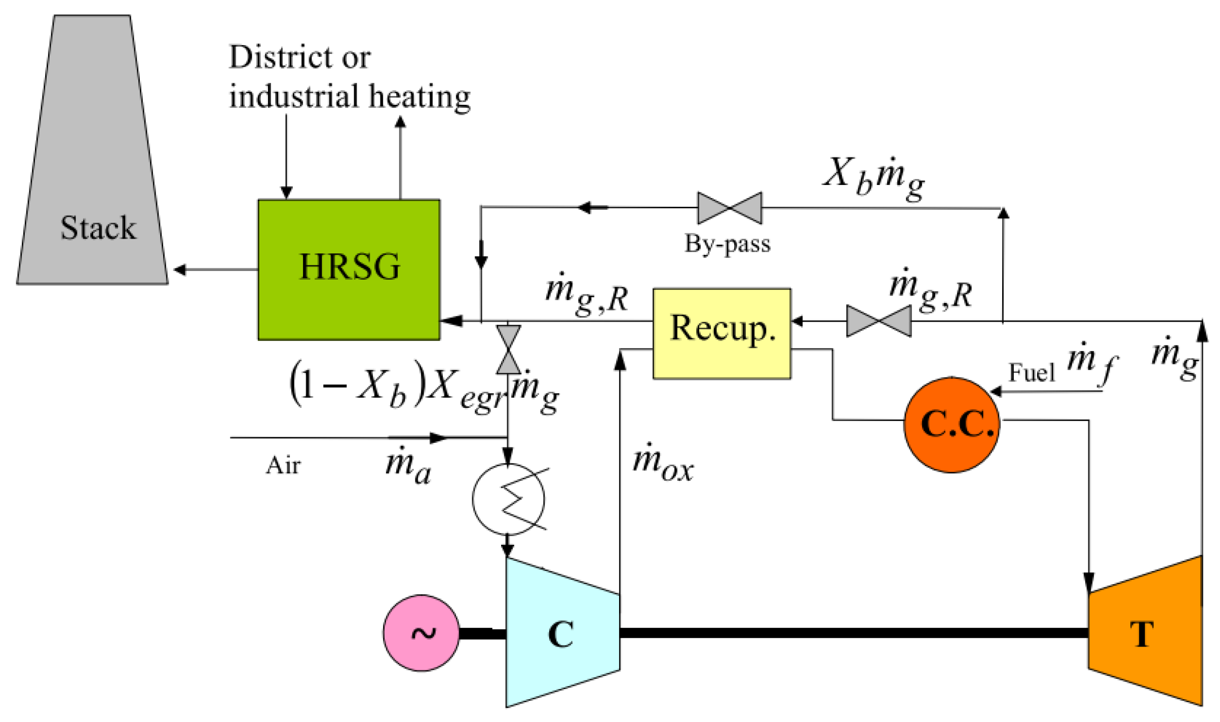
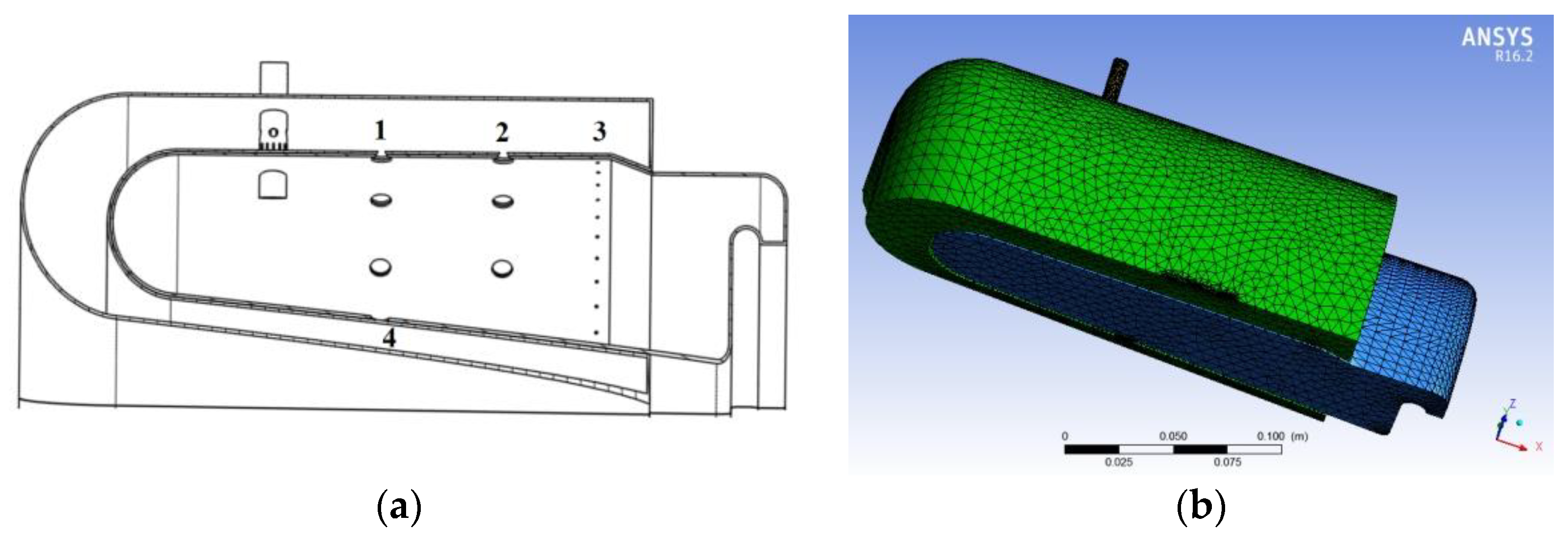
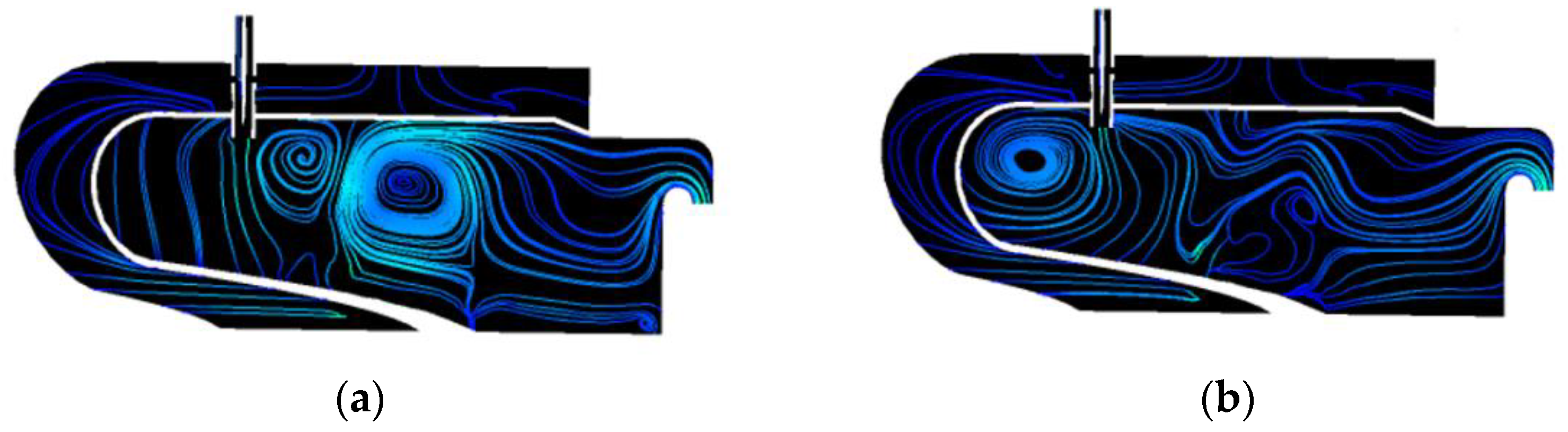
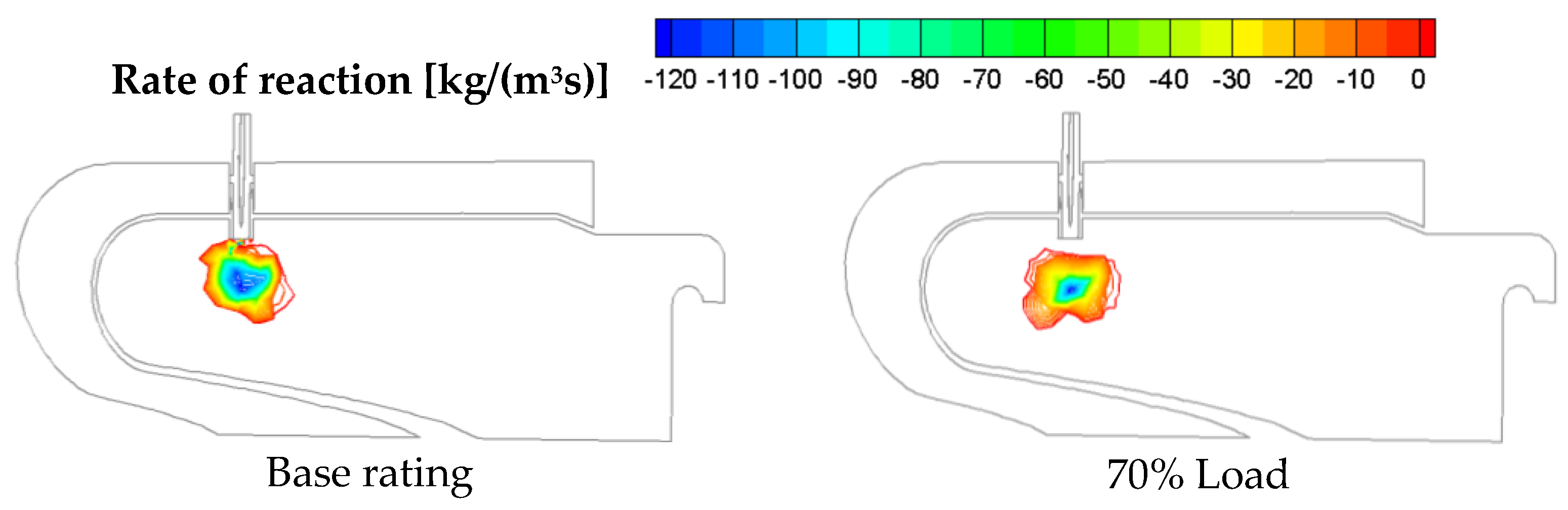
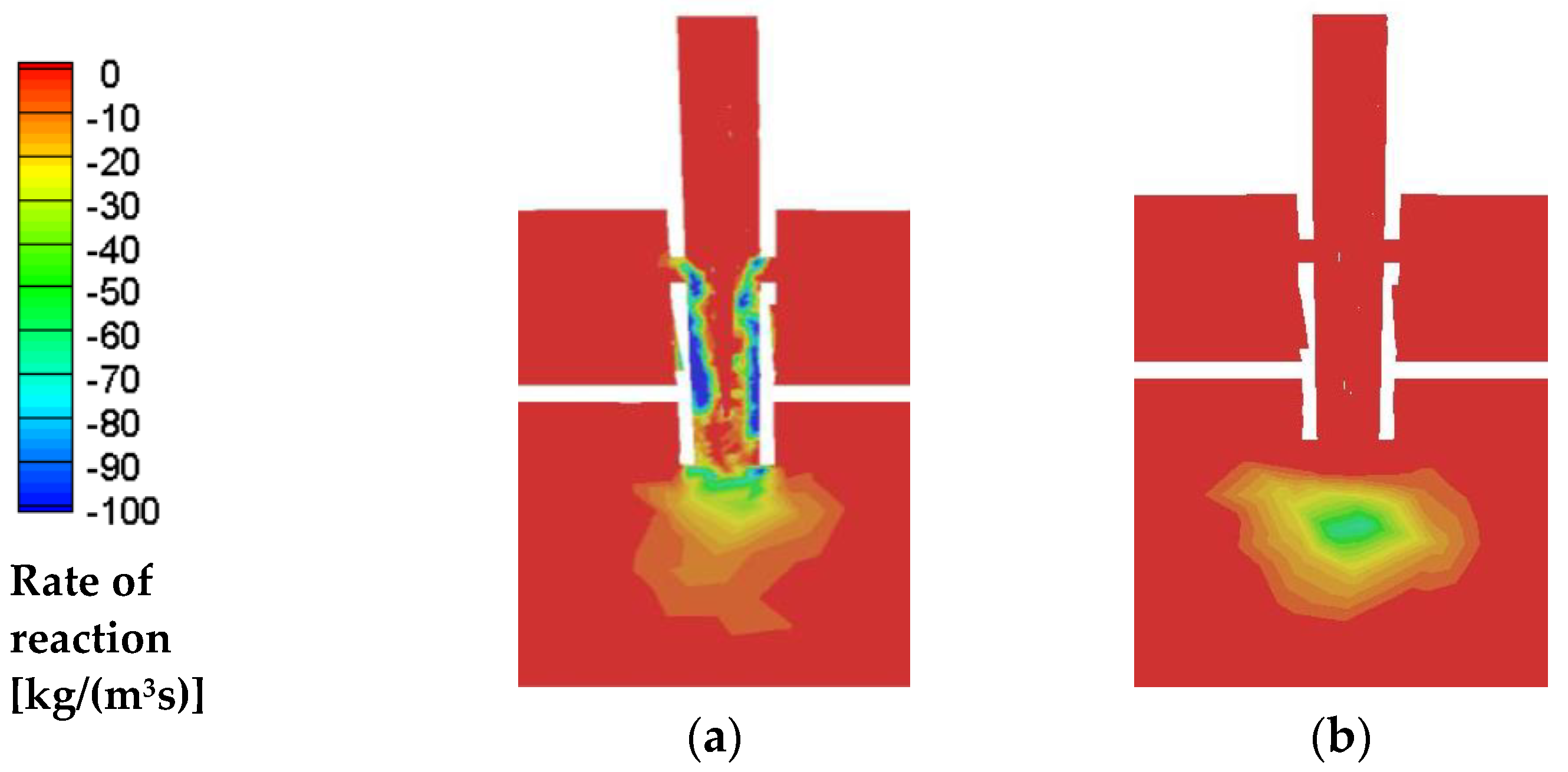
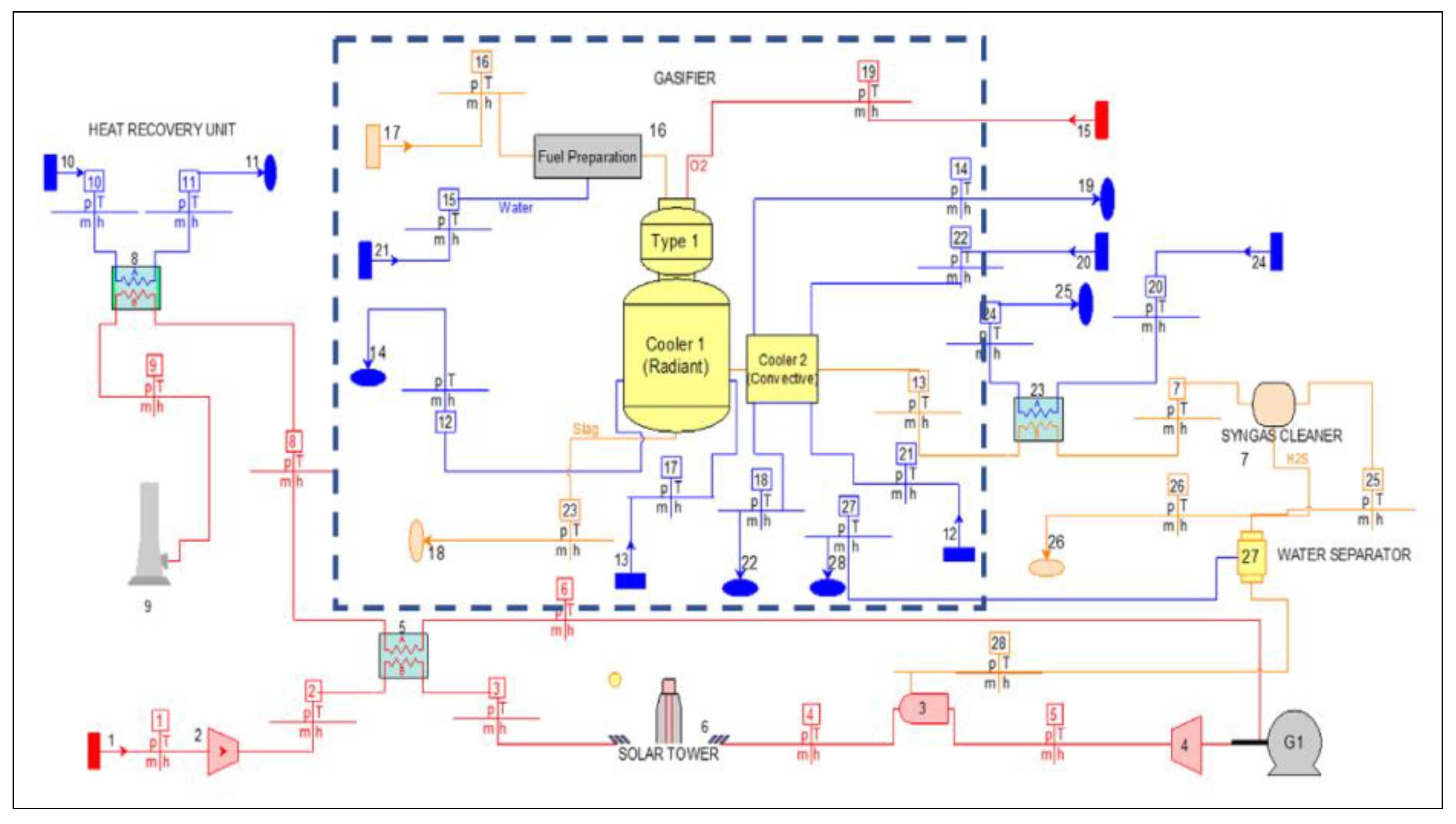
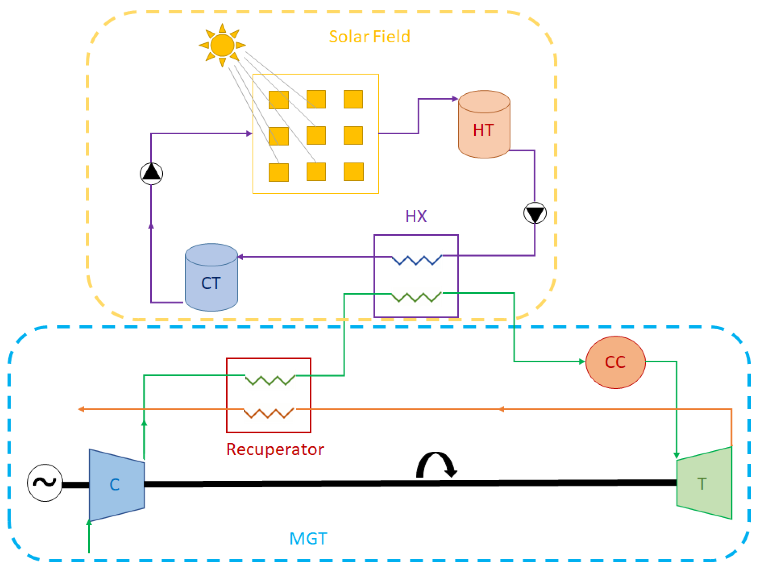
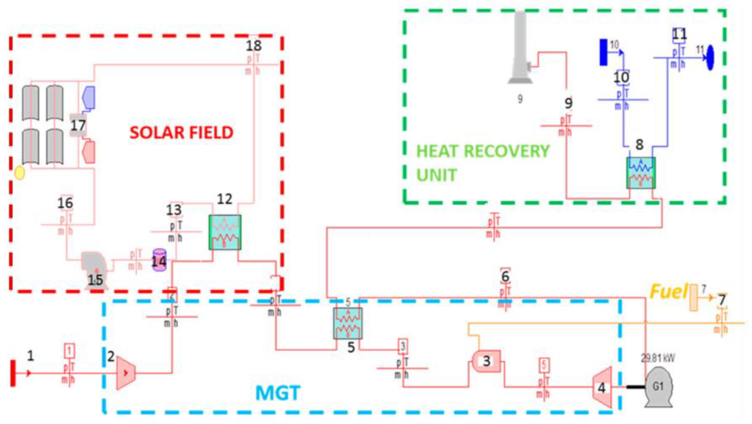
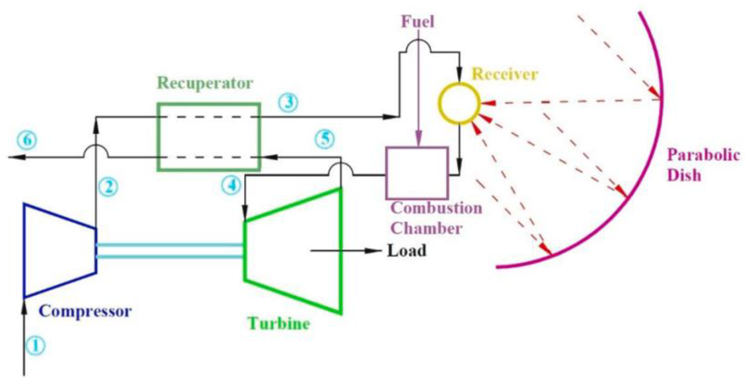
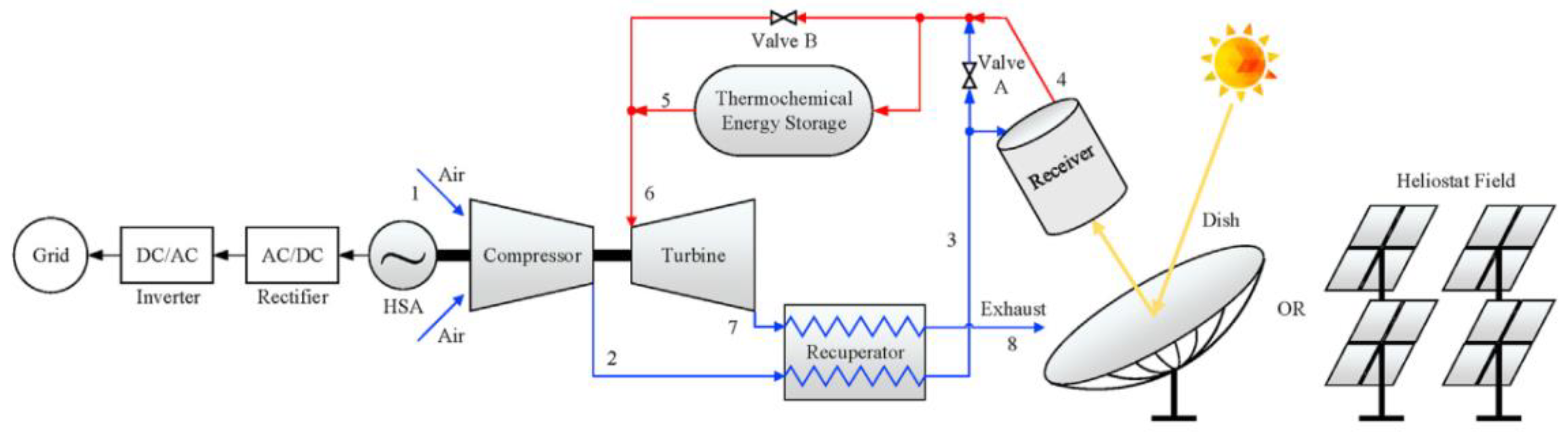
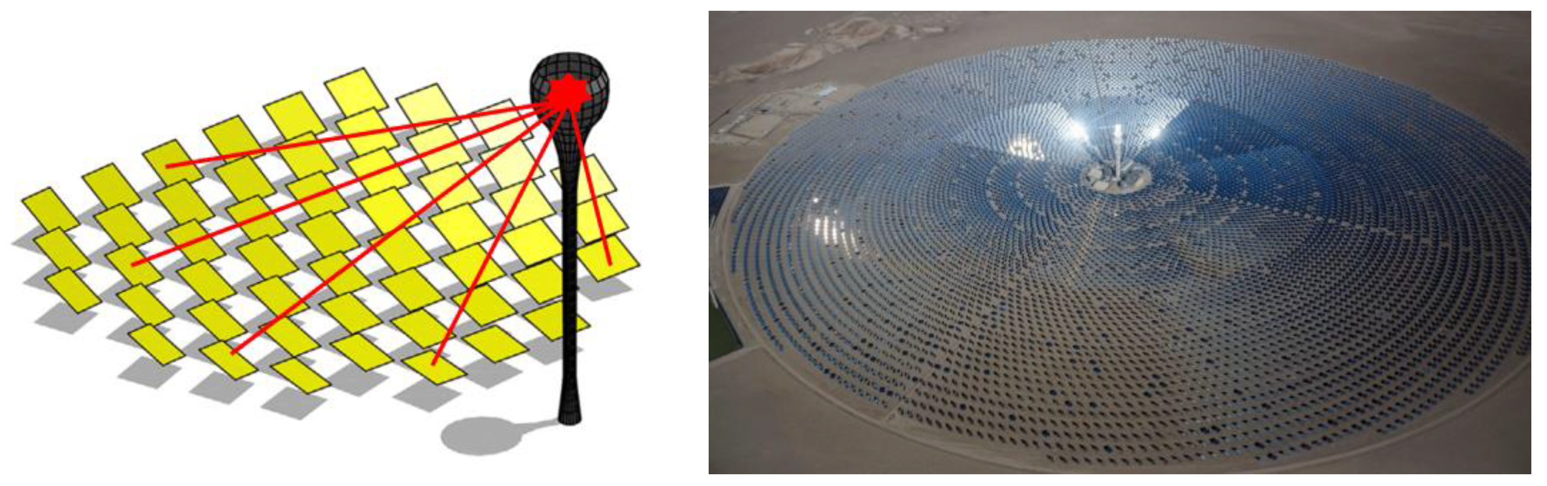
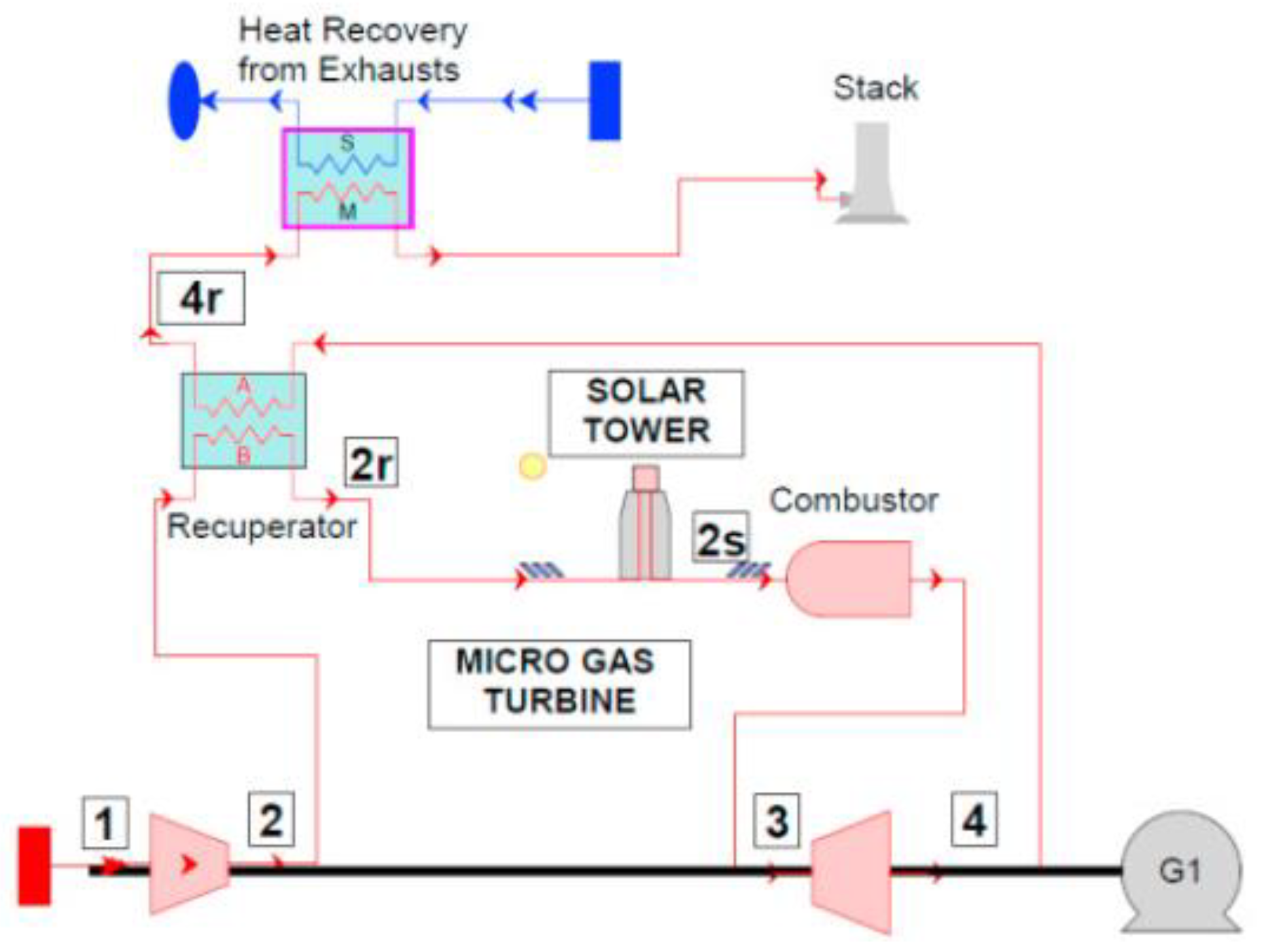
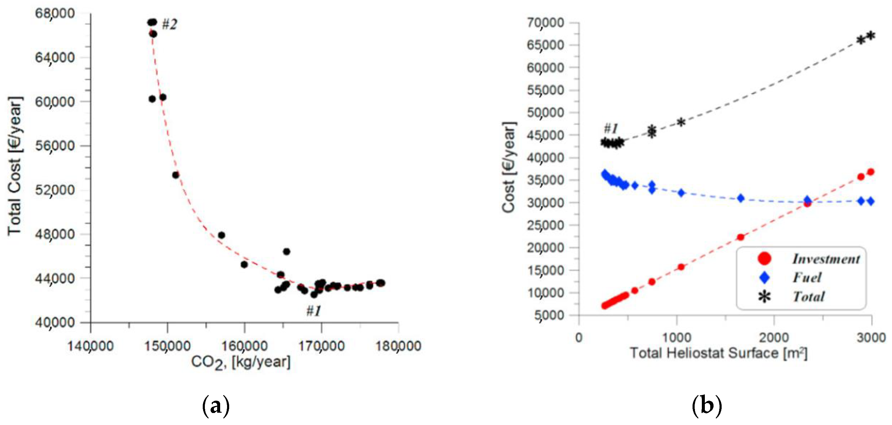
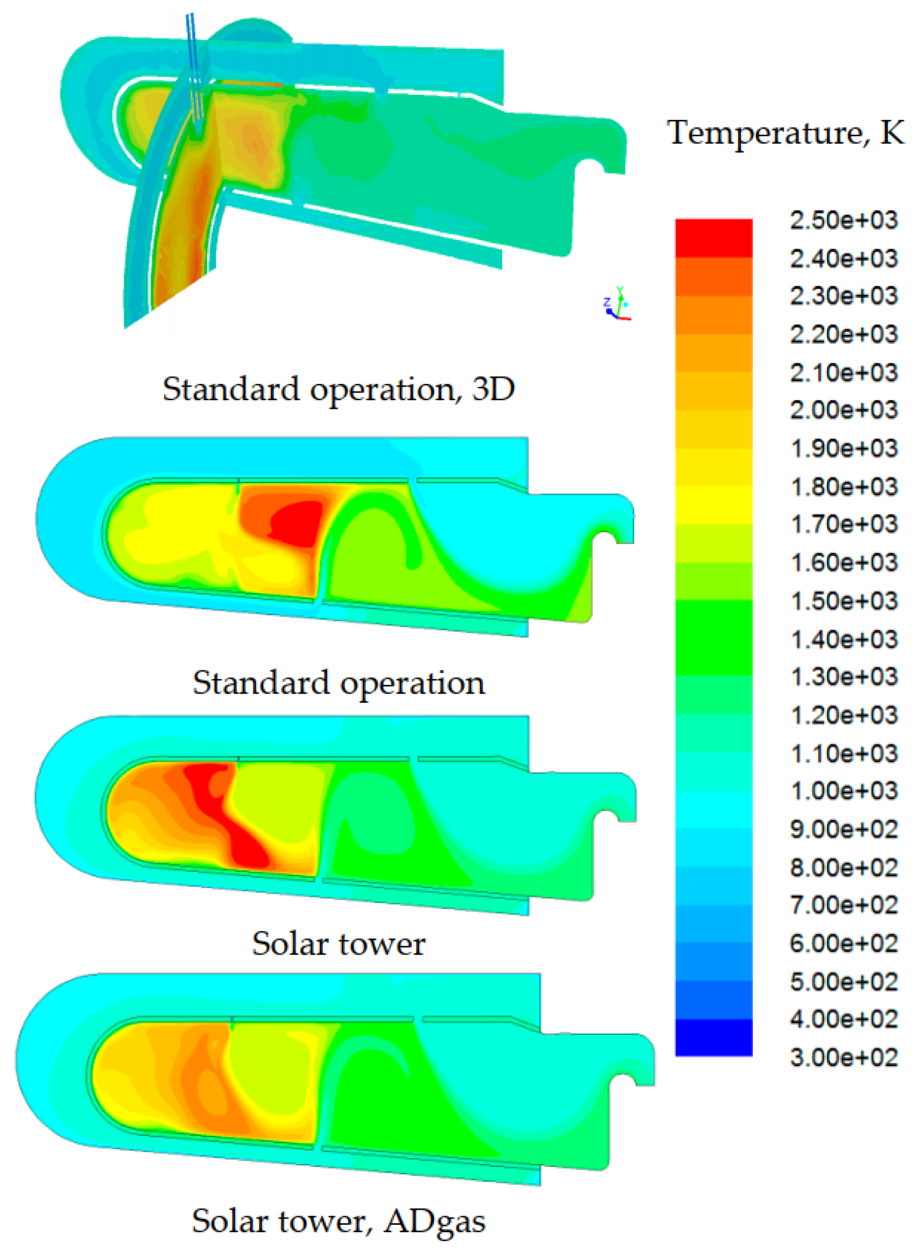
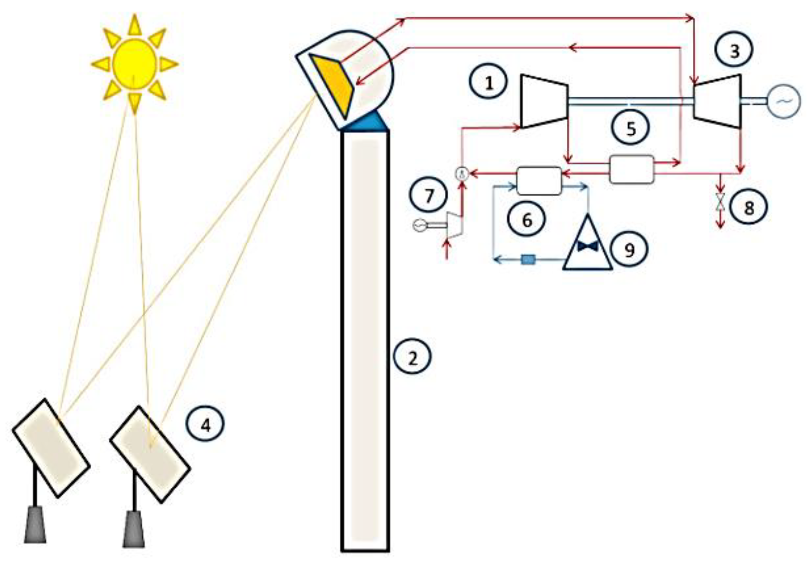
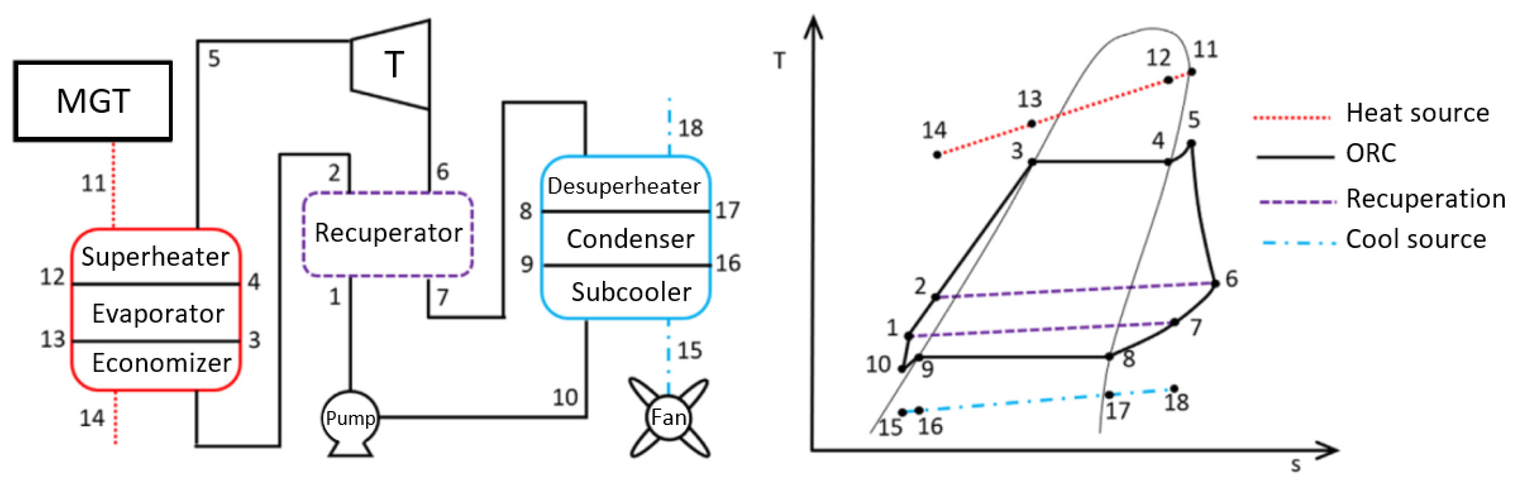
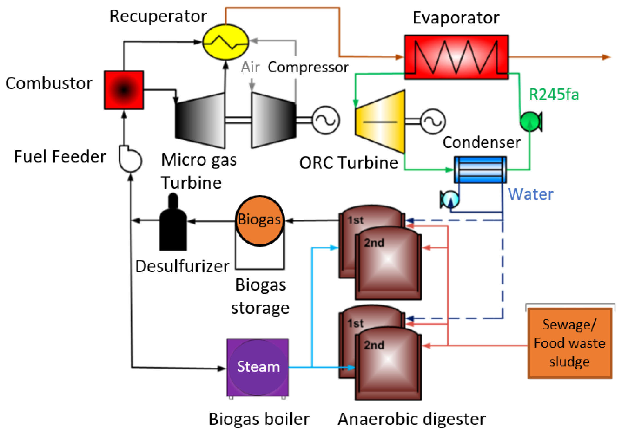
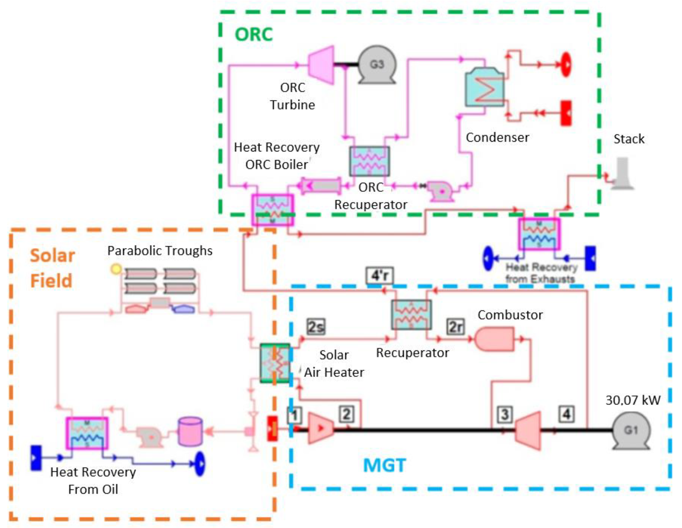
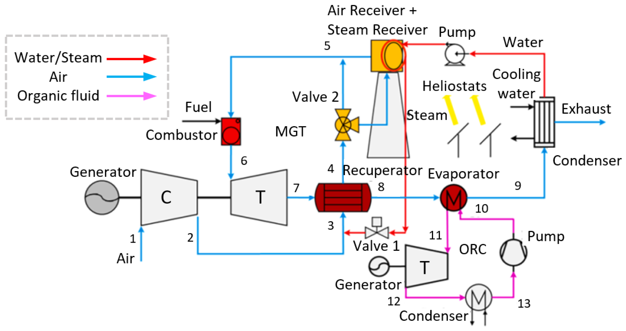
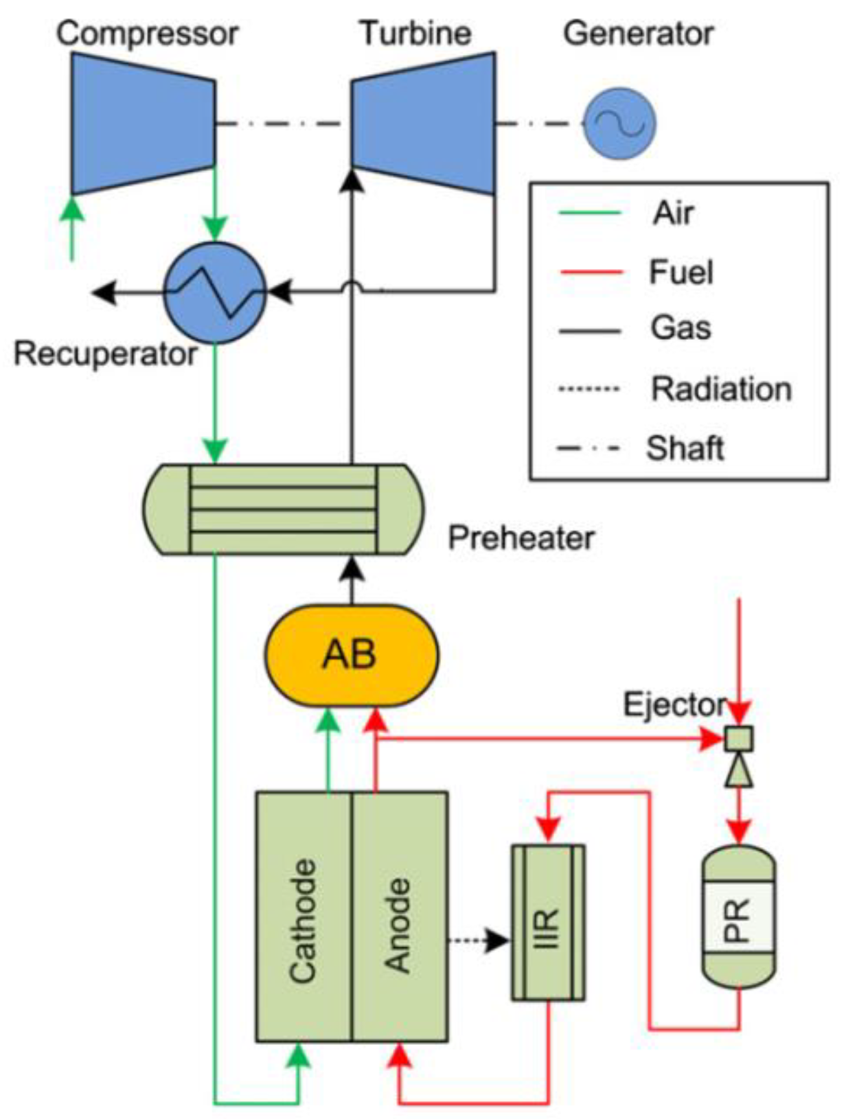
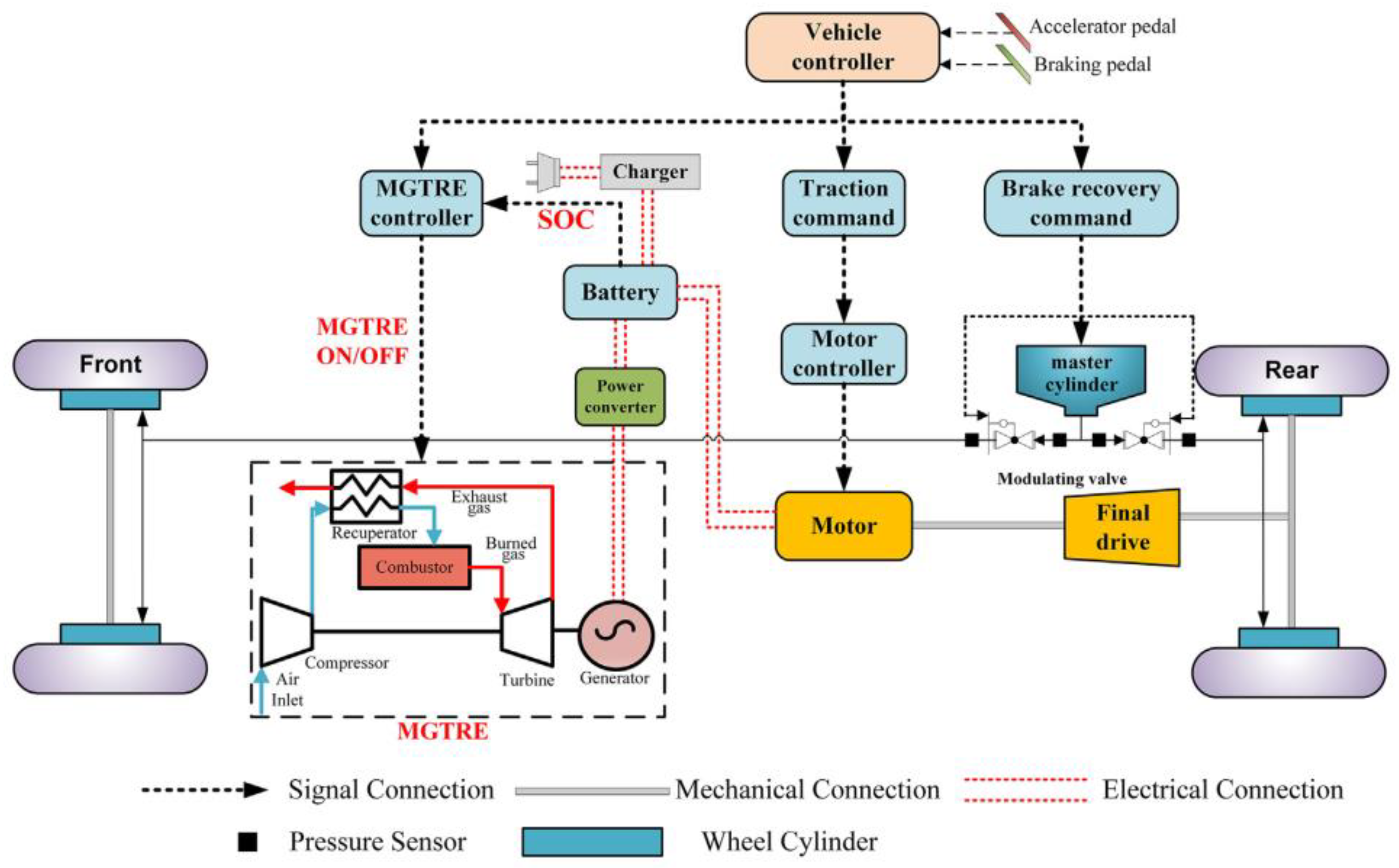
| Manufacturer | Model | Power Output | Efficiency | Pressure Ratio | TIT/EGT | Nominal Speed | CO2 |
|---|---|---|---|---|---|---|---|
| kWel | % | °C | rpm | g/kWhel | |||
| ABB [25] | MT 100 | 100 | 30 | 4.5 | 950/300 | 70,000 | 660 |
| Bladon Jets | MTG12TL | 12 | - | - | - | 134,000 | - |
| Bowman | - | 80 | 27 | 4.3 | 680/300 | 68,000 | 733.33 |
| Capstone [26] | C30 | 30 | 26 | 3.2 | 871/275 | 96,000 | 761.54 |
| C65 | 65 | 28 | 3.2 | 871/309 | 85,000 | 707.14 | |
| C200 HP | 200 | 33 | 3.2 | 870/280 | 45,000 | 600 | |
| Elliott Energy System | TA 45 | 45 | 30 | 4.0 | 871/280 | 116,000 | 660 |
| TA 80 | 80 | 30 | 4.0 | 871/280 | 68,000 | 660 | |
| TA 200 | 200 | 30 | 4.0 | 871/280 | 43,000 | 660 | |
| ET Group [27] | - | 45 | 28 | - | - | 60,000 | 707.14 |
| Honeywell (AlliedSignal) [28] | Parallon 75 | 75 | 28.5 | 3.7 | 900/250 | 85,000 | 694.74 |
| Ingersoll-Rand | - | 70 | 33 | 3.3 | 870/200 | 60,000 | 594.59 |
| MTT BV [29] | - | 3 | 16 | 2.8 | - | 240,000 | 1237.5 |
| Nissan | - | 2.6 | 8–10 | 2.8 | 850/250 | 100,000 | 2200 |
| Power WorksTM | - | 70 | 30 (HHV) | 3 | 704/- | - | 660 |
| Turbec (Ansaldo Energia) [30] | AE-T100 | 100 | 30 | 4.5 | 950/270 | 70,000 | 660 |
Table 2.
Natural gas and biogas chemical properties.
| Fuel Compos. [%, molar] | NG | BIOM O | BIOM AD | SW |
|---|---|---|---|---|
| CH4 | 92.00 | 18.00 | 65.00 | 7.00 |
| C2H6 | 3.70 | 2.00 | - - | 7.00 |
| C3H8 | 1.00 | 2.00 | - - | 7.00 |
| C4H10 | 0.25 | 2.00 | - - | - - |
| N2 | 2.90 | 8.00 | - - | - - |
| H2 | - - | 25.00 | - - | 18.00 |
| CO | - - | 33.00 | - - | 61.00 |
| CO2 | 0.15 | 10.00 | 35.00 | - - |
| H2O | - - | - - | - - | - - |
| Mol. Mass [g/mol] | 17.34 | 21.92 | 25.83 | 23.76 |
| LHV [kJ/kg] | 47,182 | 19,198 | 20,183 | 21,697 |
| fst | 0.0620 | 0.1680 | 0.145 | 0.1530 |
| Taf [K] | 2220 | 2231 | 2126 | 2300 |
| f | 0.0087 | 0.0208 | 0.0198 | 0.0184 |
| φ | 0.137 | 0.123 | 0.136 | 0.1203 |
Table 3.
Computational results [35].
Table 3.
Computational results [35].
| NG | BIOM O | BIOM AD | SW | |
|---|---|---|---|---|
| Tout [K] | 1176 | 1140 | 1165 | 1183 |
| Tmax [K] | 2557 | 2753 | 2511 | 2689 |
| NO [%] | - - | 50.6 | −31.6 | 39.8 |
| CO [%] | - - | −8.3 | 14.7 | −1.8 |
| CH4 [%] | - - | −27.7 | 44.2 | −93.0 |
Table 4.
Combustor outputs from CFD based simulations [113].
Table 4.
Combustor outputs from CFD based simulations [113].
| Standard Operation 3D | Standard Operation | Solar Tower | Solar Tower ADgas | |
|---|---|---|---|---|
| O2 [mol%] | 11.1 | 10.2 | 13.3 | 12.9 |
| Tmax [K] | 2511 | 2468 | 2480 | 2265 |
| Tmean,out [K] | 1164 | 1173 | 1147 | 1150 |
| NO [ppm] | 226 | 86 | 74 | 7 |
| CO [ppm] | 1200 | 3400 | 900 | 1300 |
| UHC [ppm] | 2 | 5 | 0.5 | 2 |
Table 5.
Working fluids properties [120].
Table 5.
Working fluids properties [120].
| MM [kg/mol] | Tcrit [°C] | pcrit [kPa] | Tsat@pamb [°C] | |
|---|---|---|---|---|
| Water | 18.01 | 374 | 22,064 | 100 |
| Butane | 58.12 | 151.98 | 3796 | −0.49 |
| Pentane | 72.15 | 196.55 | 3379 | 36.06 |
| Heptane | 100.2 | 266.98 | 2736 | 98.38 |
| Cyclopentane | 70.13 | 288.87 | 4571 | 49.26 |
| Benzene | 78.11 | 288.87 | 1894 | 80.07 |
| Toluene | 92.14 | 318.6 | 4126 | 110.6 |
Disclaimer/Publisher’s Note: The statements, opinions and data contained in all publications are solely those of the individual author(s) and contributor(s) and not of MDPI and/or the editor(s). MDPI and/or the editor(s) disclaim responsibility for any injury to people or property resulting from any ideas, methods, instructions or products referred to in the content. |
© 2023 by the author. Licensee MDPI, Basel, Switzerland. This article is an open access article distributed under the terms and conditions of the Creative Commons Attribution (CC BY) license (https://creativecommons.org/licenses/by/4.0/).
Share and Cite
MDPI and ACS Style
De Robbio, R. Micro Gas Turbine Role in Distributed Generation with Renewable Energy Sources. Energies 2023, 16, 704. https://doi.org/10.3390/en16020704
AMA Style
De Robbio R. Micro Gas Turbine Role in Distributed Generation with Renewable Energy Sources. Energies. 2023; 16(2):704. https://doi.org/10.3390/en16020704
Chicago/Turabian StyleDe Robbio, Roberta. 2023. "Micro Gas Turbine Role in Distributed Generation with Renewable Energy Sources" Energies 16, no. 2: 704. https://doi.org/10.3390/en16020704
Note that from the first issue of 2016, this journal uses article numbers instead of page numbers. See further details here.