Review

High-Temperature Materials for Complex Components in Ammonia/Hydrogen Gas Turbines: A Critical Review

1
College of Physical Sciences and Engineering, Cardiff University, Cardiff CF10 AA, UK
2
Institute of Thermal Engineering, Poznan University of Technology, 60-965 Poznan, Poland
3
Institute of Energy Research, Jiangsu University, Zhenjiang 212013, China
4
Institute of Thermal Engineering, TU Bergakademie Freiberg, 09599 Freiberg, Germany
*
Author to whom correspondence should be addressed.
Energies 2023, 16(19), 6973; https://doi.org/10.3390/en16196973
Submission received: 25 August 2023 / Revised: 13 September 2023 / Accepted: 2 October 2023 / Published: 6 October 2023

Abstract

:
This article reviews the critical role of material selection and design in ensuring efficient performance and safe operation of gas turbine engines fuelled by ammonia–hydrogen. As these energy fuels present unique combustion characteristics in turbine combustors, the identification of suitable materials becomes imperative. Detailed material characterisation is indispensable for discerning defects and degradation routes in turbine components, thereby illuminating avenues for improvement. With elevated turbine inlet temperatures, there is an augmented susceptibility to thermal degradation and mechanical shortcomings, especially in the high-pressure turbine blade—a critical life-determining component. This review highlights challenges in turbine design for ammonia–hydrogen fuels, addressing concerns like ammonia corrosion, hydrogen embrittlement, and stress corrosion cracking. To ensure engine safety and efficacy, this article advocates for leveraging advanced analytical techniques in both material development and risk evaluation, emphasising the interplay among technological progress, equipment specifications, operational criteria, and analysis methods.

1. Introduction

As we move towards a more sustainable and net-zero emission era, innovative power generation systems that leverage alternative energy fuels are gaining significant interest worldwide. The potential of hydrogen (H2) as an energy source to support a low-carbon economy has attracted considerable attention in ongoing research, reflecting the increasing urgency to mitigate the adverse impacts of climate change and global warming. However, numerous technical challenges exist, particularly concerning the storage, distribution, and sustainable usage of hydrogen [1]. Consequently, a growing body of scientific work is currently investigating the feasibility of indirect storage methods [2]. In particular, chemicals such as ammonia (NH3) are being examined as viable alternatives for hydrogen carriers and storage. Interestingly, ammonia shows promise as a potential alternative energy carrier for hydrogen due to its high hydrogen energy density, low storage costs per unit volume, and the ease of its storage and transportation processes, thus presenting it as a feasible option for energy fuels [2]. It is worth noting that ammonia is widely used as a fertiliser in agro-industries, implying that there is an already well-established infrastructure for its production, storage, and distribution. Despite those advantages, there are extant limitations and research gaps that need to be addressed. A major challenges is that ammonia exhibits unique combustion characteristics compared with hydrocarbon fuels. It has a relatively low burning velocity (~7 cm/s), low flame temperature, narrow flammability range, and requires a higher ignition energy [3,4]. It is important to note that the combustion characteristics may vary based on the conditions under which combustion occurs, such as but not limited to, temperature, pressure, and the fuel–air mixture.
Combustion of ammonia can lead to high levels of nitrogen oxide (NOx) emissions, contributing to air pollution [5]. These challenges, however, are not insurmountable, and potential solutions may involve fuel blending, incorporating fuels such as hydrogen or methane with ammonia. By doping ammonia with these fuels, the burning velocity can be improved, and the reaction can be more effectively regulated [6,7]. Such blends also bear the potential to reduce NOx emissions, thereby increasing the feasibility of ammonia as an energy production medium [6,8,9]. Further investigation is required to determine the viability of ammonia-fuel blends as a low or zero-carbon energy source and to understand any potential environmental consequences. Renowned researchers in the field, including Valera-Medina et al., 2018 [2] and Kobayashi et al., 2019 [10], have demonstrated that to fully harness the potential of ammonia as an energy source, a thorough understanding of the combustion dynamics and associated chemical reactions is essential. This comprehensive understanding would provide a foundation for addressing and overcoming the challenges presented by ammonia’s inherently low flammability and the issue of NOx emissions during combustion.
In this context, and given the inherent complexities associated with the use of ammonia as a fuel source, it is critical to investigate the role that current power generation systems, such as gas turbines, can play in addressing these challenges. The versatility and high-efficiency characteristics of gas turbines make them promising candidates for burning alternative fuels like ammonia and hydrogen [11]. However, their widespread adoption and performance optimisation are impeded by several material challenges. The high-temperature, high-pressure, and chemically aggressive environments inherent in these turbines demand materials that can withstand extreme conditions while maintaining structural integrity, functional performance, and long-term durability [12,13,14,15,16,17]. A key challenge in the development of high-temperature materials for ammonia–hydrogen gas turbines is the need for robust coatings and surface treatments to protect the materials from corrosion and oxidation. The development of such materials is essential for the commercialisation of ammonia as a carbon-free fuel. Advanced manufacturing techniques such as additive manufacturing are also being investigated for producing complex turbine components with sophisticated geometries [18,19,20,21].
In this review, we critically assess the combustion characteristics of ammonia and hydrogen within gas turbines. Understanding the interaction between these characteristics and the materials is essential for an in-depth conception of material selection, design, durability, and compatibility of turbine components. This review emphasises the significance of materials selection and design in ensuring the efficient operation of gas turbine engines fuelled with ammonia–hydrogen. The successful and safe operation of gas turbine engines relies on a combination of technological advancements, operational requirements, and analytical methodologies. Furthermore, this paper addresses the critical need for advanced high-temperature materials in complex turbine components (i.e., blades) and explores recent advancements and future directions in material development. By providing a comprehensive review and identifying research opportunities in this evolving field, our findings will benefit researchers, material scientists, engineers, and policymakers working towards sustainable energy technologies and developing efficient, reliable, and eco-friendly power generation systems. Subsequent sections will further explore the potential role of gas turbines in the context of ammonia–hydrogen combustion under gas turbine conditions and discuss strategies for optimising their performance.

2. Literature Background
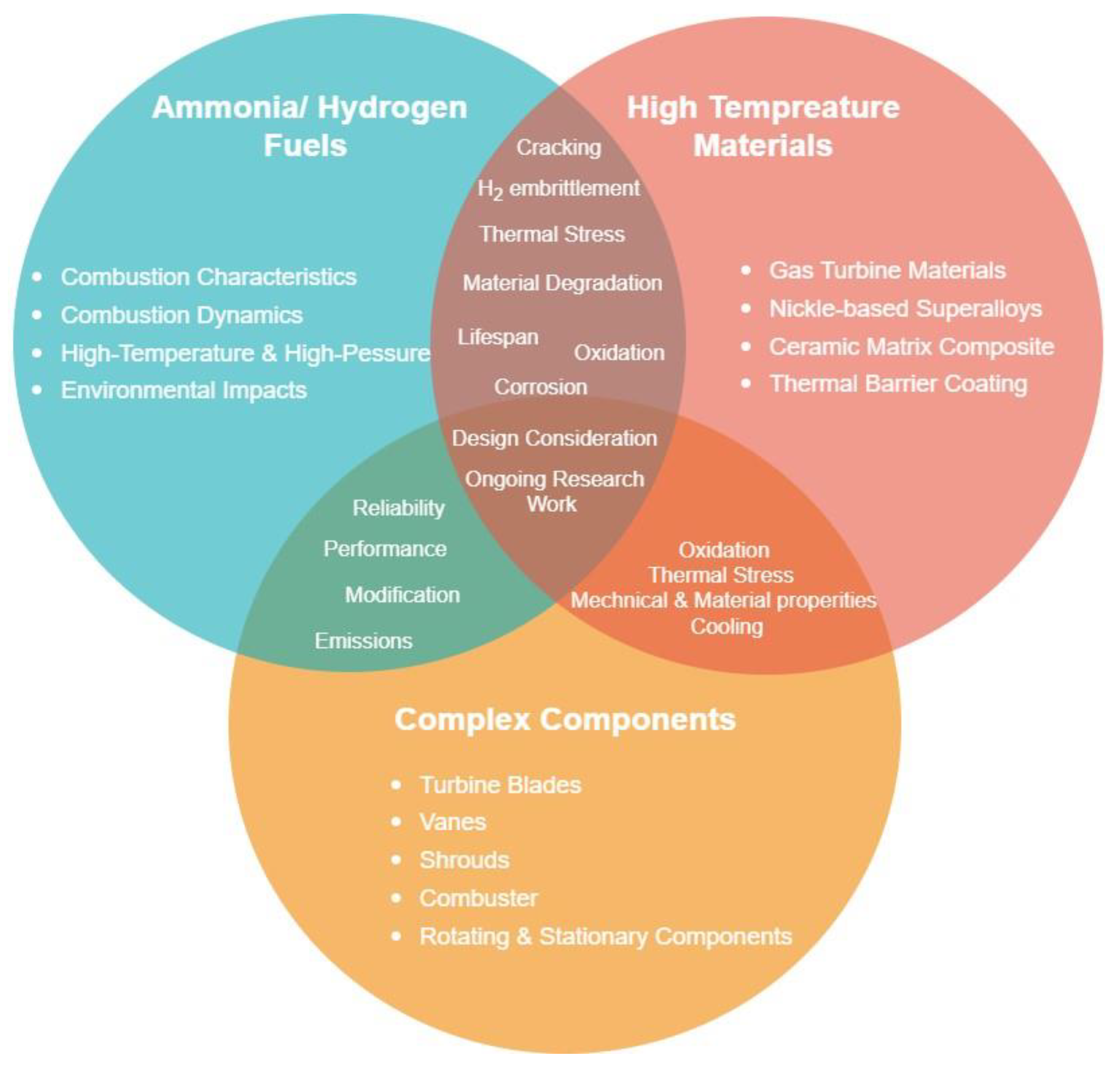
2.1. Overview

In recent academic dialogues, ammonia’s role in gas turbines has gained prominence due to its potential as a green and sustainable substitute for conventional hydrocarbon fuels. To navigate and deepen our understanding of the scholarly landscape on this topic, it is vital to comprehend both current research directions and collaborative ties among experts. In pursuit of this insight, we collated a significant collection of the literature on ammonia from the Google Scholar, Scopus, and Web of Science databases. We then conducted a comprehensive bibliometric assessment of these data. Our methodological approach revealed patterns of co-authorship, networks, and keyword associations, shedding light on scholarly collaborations and thematic interconnections. These detailed findings will be published later this year.
Highlining these findings, Figure 1 illustrates the key connections among the selected authors. Out of 1553 authors, only 34 met the criteria of having authored at least five papers on ‘gas turbines and ammonia’, with each paper receiving more than 10 citations. Two significant clusters stand out: one with authors like Kobayashi and Tsujimura from Tohoku University, Japan, and another cluster including authors from Cardiff University, UK, like Valera-Medina and Bowen. These links point to possible joint research activities at their respective universities and indicate common research topics.
Based on an in-depth co-occurrence analysis of keywords extracted from the literature on ‘gas turbines and ammonia’, a set of 34 keywords were identified. Each of these appeared over 20 times among the 2096 keywords reported in this collection. Figure 2 presents these frequently appearing keywords, with “ammonia”, “hydrogen”, “exergy analysis”, “energy”, and “optimization” standing out as the most universal across discussions of ammonia’s role in gas turbines. The three discrete clusters, coded in red, green, and blue hues, indicate distinct research areas like ammonia combustion, gas turbine systems, and affiliated subjects such as renewable energy and power generation.
The results underscore key focal points in this area, emphasising efforts to improve the performance of ammonia-driven gas turbine engines with methodical optimisation, in-depth exergy analysis, and the investigation of substitute fuels like hydrogen, methane, or biomass. Moreover, there is a marked focus on a reduction in specific emissions, especially NOx. Researchers also seem increasingly involved in foundational topics like laminar flame velocity and Markstein length, indicating a drive to understand fundamental combustion processes and flame behaviours within ammonia-powered gas turbines. Collectively, these revelations offer a record of current research trajectories and the academic community’s endeavours to advance eco-friendly and efficient gas turbine solutions driven by ammonia.
A thorough analysis was conducted to identify emerging research themes and to illuminate the complex interrelationships within the field of ammonia-driven gas turbines. This paper presents insights from an extensive review spanning six decades. This paper is structured as follows: Section 2.2 provides a systematic literature review on the characteristics of combustion of ammonia, hydrogen, and ammonia–hydrogen blends under gas turbine conditions; Section 2.3 includes the challenges in design and material selection for gas turbines powered by ammonia and hydrogen fuels; and Section 3 provides a summary and identifies research gaps and future directions, which summarise the main findings of the conducted study.

2.2. Characteristics of Ammonia–Hydrogen Combustion in Gas Turbines

Understanding how ammonia–hydrogen reacts with materials is essential. Thus, studying their relevant characteristics in gas turbines becomes important.

2.2.1. Hydrogen in Gas Turbines

Since its invention in the early 20th century, the gas turbine, normally fuelled by natural gas and diesel, has been used for electricity generation, propulsion and aviation [23]. Hydrogen can be combusted in a gas turbine [24]; however, the distinction between hydrogen and other hydrocarbon fuels introduces complexities when transitioning to hydrogen usage. Given that turbines have been principally designed and optimised for natural gas combustion, these variances necessitate specific modifications to the turbines to facilitate a complete hydrogen combustion [25,26]. The challenges associated with hydrogen combustion mainly arise from its high reactivity and unique physical properties [25]. Hydrogen’s high reactivity causes higher flame speed and flame temperatures, and lower auto-ignition delay [27,28]. High flame speeds can result in combustion occurring outside the designated combustion zone. High flame temperatures can lead to significant challenges including the degradation of turbine materials and the need for advanced cooling techniques [29,30]. Furthermore, the elevated temperatures can compromise turbine efficiency, introduce combustion instabilities, and alter acoustic signatures, potentially causing resonance phenomena [31,32]. Moreover, the distinctive flame characteristics of hydrogen need vigilant operational management, given its broad flammability limits, and raise concerns regarding both erosion of turbine components and the overarching safety [33,34]. The lower autoignition temperature for hydrogen denotes a reduced energy need for initiating combustion, which potentially can cause the combustion reaction to occur too early [35]. Hydrogen’s flame speed significantly exceeds that of natural gas by over threefold, implying conventional combustors may not be able to handle hydrogen’s flame dynamics, thus risking damage [32,35]. Given hydrogen’s lower volumetric heating value, triple the flow rate is required for equivalent power outputs compared with natural gas. Thus, gas turbines that utilise hydrogen demand flow rate adjustments [32]. In addition, hydrogen’s minuscule molecular structure might induce leakages through components designed for natural gas, presenting risks due to its invisibility and flammability. Transitioning to hydrogen offers the benefit of CO2 emissions reduction, although its combustion might influence NOx emissions [24,28,32,35]. To overcome these issues, one might consider the deployment of advanced combustion techniques, utilising improved turbine materials and enhancing operational controls. Adjusting the turbine’s compressor may address the lower volumetric heating value of hydrogen. Implementing redesigned piping, enclosures, and flame detectors might mitigate associated hazards [25,36]. Nevertheless, the most fundamental alteration pertains to the combustor [37].
Thermodynamically, temperature and pressure are critical variables that affect the cycle’s effectiveness and characteristics. Gas turbines with a higher inlet pressure result in improved exergy and thermal efficiency, while those with a higher outlet pressure decrease these attributes. The cycle’s exergy and thermal efficiency are directly affected by higher turbine inlet temperatures [38]. The flame temperature generally increases with the hydrogen fraction in fuel mixtures. The curve of the flame temperature exhibits two linear regimes, with a higher rate of temperature growth when the hydrogen (H2) fraction exceeds 90%, indicating H2 dominance in the second regime, as shown in Figure 3 [39,40]. Hydrogen-doped ammonia can be used as a carbon-free fuel, and NH3/H2/air flames attain higher maximum flame temperatures with higher H2 content [41]. All equivalence ratios studied have shown increased normalised heat release rates with H2 addition. With an increase in hydrogen proportion, maximum heat release occurs at lower temperatures in stoichiometric and fuel lean zones. Fuel-rich and stoichiometric regions still have a higher rate of heat release in general [39,42].
Recently, dry low NOx (DLN) burners have dominated the gas turbine burner landscape [43]. These burners reduce NOx formation in flue gas by premixing fuel and air, which decreases flame temperature. However, they were not originally designed to handle the conditions of hydrogen combustion such as its rapid ignition before complete premixing [32,35]. Pure hydrogen combustion mandates non-DLN burners, which either partially premix or dilute fuel using nitrogen and steam to curb NOx emissions [32]. General Electric (GE) claimed that using their non-DLN burners has attained up to 100% hydrogen combustion [44]. Nevertheless, the bulk of modern large-scale turbines use DLN burners. Thus, an alternative solution is blending hydrogen and natural gas. Limited hydrogen addition does not impede performance but can decrease emissions [10,45,46].
Siemens’ robust gas turbines can manage fuel mixes with up to 30%vol hydrogen, with larger percentages for smaller units [25,47]. GE’s larger turbines can accommodate between 15%vol and 33%vol hydrogen, and Mitsubishi’s offerings can support 30%vol [44,48]. These figures pertain to potentially altered new turbines. Fuel variation may affect turbine efficiency. Thermodynamic research indicates that hydrogen–natural gas mixtures in turbines could enhance efficiency [49,50,51,52]. Nevertheless, real-world effects might differ due to retrofitting measures for hydrogen compatibility. Some studies demonstrated a potential efficiency drop [50,53]. However, Ansaldo Energy has reportedly run a gas turbine with 70%vol hydrogen without efficiency loss. Several commercial examples exist of turbines on high hydrogen fuel concentrations [54,55]. A GE turbine in Korea has operated on a minimum of 70% hydrogen for two decades [56]. A 485 MW combined-cycle plant in the USA aims to achieve 100% hydrogen combustion by 2030, starting at 20% [57,58]. Under the HYFLEXPOWER initiative, a Siemens turbine will be retrofitted for hydrogen, and an Italian power plant recently emerged as the first to operate solely on hydrogen [59,60,61].

2.2.2. Ammonia in Gas Turbines

Ammonia has been considered a potential fuel for many decades, with interests peaking at different times, particularly during the energy crises of the 1970s and shifts in energy paradigms [62]. The direct utilisation of ammonia as a fuel for internal and external combustion systems is not a new idea or commercial on a large scale. There have been instances of ammonia being used in internal combustion engines between the 1970s and 1980s and other applications on laboratory scales [63]. However, ammonia’s potential is due to its widespread production and its storage and handling infrastructure, primarily for agricultural purposes. In terms of global production, ammonia ranks second after sulfuric acid, boasting an annual yield of over 250 million tonnes in 2023 [64], making ammonia an indispensable element in agricultural, industrial, and potential clean energy applications worldwide. The interest in ammonia as a fuel in recent years is due to its potential as a carbon-free source, especially when it is synthesised using renewables such as solar and wind power [2]. Its utility as a hydrogen carrier becomes of great interest when it is decomposed. Ammonia serves both as a direct fuel and a hydrogen carrier [2]. Its higher volumetric energy density compared with hydrogen makes it a more spatially efficient storage medium.
Despite hydrogen’s superior gravimetric energy density of 120 MJ/kg, its volumetric energy density lags behind conventional fossil fuels with values of 8.49 MJ/L (liquid form) and 4.5 MJ/L (compressed) [65]. In contrast, ammonia’s gravimetric and volumetric energy densities are 18.8 MJ/kg and 12.7 MJ/L, respectively [2,65]. Ammonia storage conditions are more moderate than those for hydrogen, allowing it to be stored as a liquid at ambient temperature with about 10 bar pressure or at −33.4 °C (−28.12 °F) under atmospheric pressure [65]. This facilitates more energy-efficient storage with minimal boil-off losses. Its properties, including a high autoignition temperature of 650 °C (1202 °F) and greater density in both liquid and gaseous states compared with hydrogen, make its storage and transport logistics more favourable [66]. One drawback, however, is the energy-intensive reconversion of ammonia to hydrogen gas [67]. While ammonia’s toxicity warrants caution, existing infrastructure manages this risk effectively [68]. In other words, ammonia can overcome the complexities associated with hydrogen storage and distribution, and its complexities are significantly less than those associated with hydrogen.
The concept of using ammonia as a fuel has roots going back to the early 20th century, but the exact “first” use can be challenging to pin down due to miscellaneous applications and research initiatives over the years. Ammonia’s potential as an energy carrier is not entirely new, even if its adoption on a large scale is still emerging. During the Second World War, conventional fuel shortage led Belgium to power buses using ammonia [69]. A more avant-garde application came in the 1960s when the U.S.A. utilised ammonia as a fuel in the groundbreaking X15 aircraft [70]. This period of innovation continued with explorations into ammonia’s viability for gas turbines and reciprocating engines [62]. Despite the unidentified outcomes from these studies, the historical precedents set the stage for renewed interest in ammonia as a sustainable energy solution in today’s context.
Previous work has shown that the combustion of ammonia presents poor characteristics, including poor reactivity, slow-burning velocity, narrow flammability range, high auto-ignition temperature, and a propensity for excessive NOx emissions [10,71]. Upon ignition, ammonia exhibited an adiabatic flame temperature lower than both hydrogen and natural gas, being recorded at 1800 °C (3272 °F), 2110 °C (3812 °F), and 1950 °C (3542 °F), respectively. The combined effects of this lower temperature and the absence of CO2 in the resultant gases led to reduced radiative heat transfer, thereby impeding combustion [65,72]. Ammonia also exhibited lower laminar burning velocities compared with hydrogen and natural gas, with values of 0.07 m/s, 2.91 m/s, and 0.37 m/s, respectively [73,74]. Furthermore, its narrow flammability range further exacerbated ignition challenges. A significant concern with ammonia combustion is the potential for NOx emissions. Stoichiometric combustion of ammonia did not produce NOx. Nevertheless, under actual conditions, nitrogen-containing radicals might be generated, leading to NOx formation [74]. However, NOx removal technologies were mature, and strategies like selective catalytic reduction (SCR) were available to mitigate such emissions [75]. Interestingly, ammonia from the fuel might have been utilised for this purpose [65]. The presence of potential unburned ammonia presented an issue due to its toxic nature [73]. Furthermore, it was found that ammonia could lead to corrosion in materials, warranting careful consideration. Various strategies exist for enhancing the combustion process [76]. Using gaseous ammonia over its liquid form, integrating combustion additives, and incorporating a swirler and flame holder are all established methods that have been proven to enhance combustion stability and efficiency while reducing NOx emissions [77,78]. Another opportunity being explored involves blending with other fuels [79,80]. This secondary fuel might serve solely as an ignition aid or be part of a continuous fuel blend. Studies have indicated that the efficiency of ammonia combustion can be significantly improved with the inclusion of auxiliary fuels, such as hydrogen and methane [81,82,83].
Combustors, simulating those found in gas turbines, have been tested with a blend of ammonia and hydrogen [84,85,86]. These experimental trials resulted in a significant increase in laminar flame velocity. Nevertheless, this enhancement was accompanied by an increased radical formation, which subsequently escalated NOx emissions and shortened the combustion process’s operational range [65]. Conversely, some research indicates that the incorporation of hydrogen can attenuate the NOx formation [2]. Mixtures of ammonia with hydrocarbons have demonstrated augmented flame velocity and enhanced radiation heat transfer [87]. A remarkable reduction in CO2 emissions was attributed to a reduced hydrocarbon utilisation, indicating such blends could be key in transitioning from carbon-intensive fuels. However, an increased ammonia concentration might pose risks of heightened NOx emissions [65]. The key challenges in combusting ammonia in gas turbines revolve around its limited flammability, combustion instability, and potential NOx emissions [88]. Previous research in this domain has largely been confined to small-scale experiments under specific conditions. In Japan, combustion studies involving both pure ammonia and an ammonia–methane blend were combusted in a 50 kW turbine [74]. The process’s combustion efficiency was determined by comparing the thermal efficiency (based on the fuel’s LHV) to the efficiency of pure natural gas combustion. Results for pure ammonia floated between 89% and 96%, while the blend showed between 93% and 100%. Furthermore, the turbine exhibited operational flexibility with the mixed fuel, functioning even below 40% of its rated capacity [74]. Ammonia was also introduced into a commercial coal-fired power plant in Japan. Although the addition was minimal on an energy scale (0.6–0.8%), there was a notable reduction in CO2 emissions without compromising efficiency [2]. Experimental setups using small-scale gas turbine burners have successfully achieved stable flames with blends containing up to 80%vol ammonia with methane and 50%vol ammonia with hydrogen [89].
Ammonia cracking is a process that decomposes ammonia into hydrogen and nitrogen gases, offering a potential source of hydrogen fuel or hydrogen–ammonia blends for gas turbines [74]. This process essentially mirrors the synthesis of ammonia [90]. The catalyst type determines the necessary operational temperature. For instance, ruthenium-based catalysts are effective at approximately 500 °C, but efforts are underway to identify catalysts that operate at reduced temperatures [62]. Regarding capacity, ammonia crackers have been engineered to handle up to 10 tons per hour [91]. The debate between direct ammonia utilisation versus its decomposition remains unresolved. While Aziz et al. [65] encourage the direct use of ammonia in combustion or fuel cells, Ikäheimo et al. [92] support the decomposition of ammonia followed by hydrogen combustion. Alboshmina [16] conducted a comprehensive study that introduces the development and evaluation of an innovative cracker system that utilises energy derived from the combustion process for the pre-cracking of ammonia. A distinct geometry, which was validated with testing, has been shown to supply the requisite energy for the cracking mechanism while simultaneously establishing recirculation domains that bolster flame stabilisation. Furthermore, the research succeeded in reducing NOx emission levels by incorporating a minor proportion of the fuel mixture into the area preceding the cracker and following the burner. Both computational and empirical findings ascertain that a specific design—namely, a hemispherically tipped bluff body—positioned at the heart of a swirl combustor can amplify flame resilience (manifested as enhanced resistance to blowoff), cultivate expansive recirculation areas for protracted residence durations, and utilise the anchoring apparatuses that secure the cracker to distribute uncombusted ammonia for NOx regulation objectives. Consequently, the system outlined therein is judged to be suitable for ammonia-based fuel applications, predicting a reduction in NOx emissions while facilitating the effective combustion of ammonia-rich mixtures.

2.2.3. Advancements in Ammonia–Hydrogen Co-Firing in Gas Turbines

In 1936, J. Breton [93] measured the detonation velocity of ammonia–oxygen mixture and the results revealed that there are detonation boundaries (25.4–75.0% at 1500 m/s), similar to flammability limits, beyond which consistent detonation is not observed. Information on the phenomenon was experimentally observed. In 1967, Verkampf et al. [94] conducted experimental investigations to assess the minimum ignition energy, quenching distance, flame stability limits, and performance in gas turbine burners when utilising ammonia–air mixtures. Relative to propane, which has a minimum ignition energy of less than 0.5 millijoules, ammonia exhibited a significantly higher value of 8 millijoules. Under stoichiometric conditions, the quenching distance of ammonia–air stood at 0.275 inches, in contrast with the recorded 0.08 inches for propane–air. Flame stability assessments showed that ammonia combusted at merely half the air-flow velocity achievable with hydrocarbon fuels, and the stable flame’s equivalence ratio range was notably more restricted than that of hydrocarbon fuels. These results were corroborated during gas turbine burner evaluations. The study concluded that, in the absence of augmentations like enhancing ignition system energy, expanding the combustion liner diameter approximately twofold, and gaseous state ammonia injection, conventional gas turbine burners cannot use pure ammonia as a direct replacement for hydrocarbons. Two strategies to enhance ammonia’s combustion characteristics were explored: the introduction of additives and ammonia’s partial pre-dissociation. Additives, assessed within the flame stability apparatus, constituted 5% by volume of the overall fuel. At this concentration, no additive sufficiently enhanced the flame stability parameters. Notably, 28% dissociated ammonia represented the minimum ignition energy, quenching distance, and flame stability attributes of methane. Subsequent testing of partially dissociated ammonia in a gas turbine burner suggested that gas turbine combustion systems, designed optimally for hydrocarbon fuels, could feasibly utilise 28% dissociated ammonia as an alternative fuel source.
Over the years, significant strides have been made in understanding how to effectively use ammonia as an alternative fuel. Many studies have been focused on transportation applications [5], exploring ammonia combustion in spark-ignition (SI) gasoline engines [95,96] and compression-ignition (CI) diesel engines [97,98]. In these studies, ammonia is mixed with other fuels such as hydrogen, diesel, gasoline, biodiesel, and other fuels to enhance combustion performance. The results have shown that using ammonia-based fuels for power generation is an enticing prospect, particularly for complementing intermittent renewable energy sources like wind and solar. Given the widespread deployment of gas turbine power plants for electricity generation in recent years and the urgent need to reduce carbon dioxide emissions, the concept of utilising ammonia–hydrogen in gas turbines presents a noteworthy opportunity [9].
Initial research conducted in this century on ammonia combustion in gas turbines illustrates some challenges, such as ammonia’s lower reactivity and the requirement for higher ignition energy compared with conventional fossil fuels [9,99]. A team of researchers from Cardiff University conducted many studies on the combustion of alternative fuel blends of ammonia/hydrogen/methane in a laboratory-scale generic swirl burner for large combustion applications [89,100,101]. The results from the swirl burner demonstrated the need for an innovative injection approach to maintain combustion stability, particularly when injecting hydrogen with ammonia. Xiao et al. [9] developed a comprehensive chemical–kinetic mechanism to facilitate the use of ammonia–hydrogen blends as a viable alternative fuel source for gas turbine power generation systems. Their mechanism/model renovated and advanced the kinetic mechanism, utilising Mathieu’s model [99] as a base. Mathieu’s model was originally built for shock-tube experiments on ammonia ignition delay time measurements under high pressure of up to 30 bars. Xiao’s model accuracy was simulated and examined by evaluating parameters such as NOx emissions, ignition delay times, and laminar burning velocity, with particular attention paid to high-stress conditions usually associated with gas turbine operation. Under such conditions, the model was proficient at predicting various phenomena, including autoignition, flashback, and emission characteristics. Furthermore, in comparison with other mechanisms presented in the study by Xiao et al. [9], the findings exhibited satisfactory accuracy of the proposed model under varying practical equivalence ratio conditions. Figure 4 presents the potential of utilising ammonia–hydrogen fuels in gas turbine combustors in terms of NOx emissions and the NO mechanism, respectively, under pressurised conditions. The simulation data were presented against experimental data sets available in Refs. [99,102].
It can be clearly seen from Figure 4 that NOx emissions decrease with the increase of pressure. In addition, the NO sub-mechanism showed good agreement with the NO profile of Mathieu’s model [99] under 10 bars. These findings provide a valuable resource for shaping the design of micro-gas turbine combustors. However, the results of the laminar burning velocity under various equivalence ratios revealed a decrease in the burning velocity of the ammonia–hydrogen mixture with the increase in the ammonia concentration. A good agreement was observed between the simulation and experimental data on the laminar burning velocity when the ammonia mole fraction was varied between 45 and 70% under fuel lean (150–450 mm/s), stoichiometric (200–600 mm/s), and rich (250–600 mm/s) conditions. A good agreement was also observed between the simulation and experimental data of the ignition delay time (100–1000 µs) at 30 bars and under fuel lean stoichiometric and rich conditions. Moreover, in the pursuit of a more universally applicable model, the team simplified the proposed mechanism and evaluated it within the framework of a 2D large-eddy simulation, representing the turbulent combustion of ammonia/hydrogen fuels under gas turbine conditions. This simplified version maintained a strong correlation with the parent model while providing enhanced computational efficiency and thus paving the way for detailed ammonia chemistry applications in future computational fluid dynamics (CFD) analyses under gas turbine combustion conditions. Consequently, the resulting model is therefore more suited for use in 3D CFD simulation studies of operational gas turbine combustors.
In a numerical study conducted by Hewlett et al. [72], the feasibility of utilising by-product ammonia, generated from every tonne of steel produced using blast furnace processes within the steelworks industry, for gas turbine power generation was investigated. This ammonia, largely obtained in a vapour state, is created from the purification process of coke oven gas (COG). In 2017, the global production of by-product ammonia within the steel industry was estimated at 1.7 Mt. This inspires researchers to investigate by-product ammonia present in the waste streams of many other industries such as oil refining, dairy farming, and biomass processing. CHEMKIN-PRO software was utilised to determine the optimal proportion of ammonia vapour, and in a separate instance, anhydrous ammonia derived from said vapour, when mixed with COG or methane at equivalence ratios ranging between 1.0 and 1.4 under an elevated input temperature of 550 K. Under this condition for pure anhydrous ammonia, NOx and CO concentrations were found to range from 600 ppm to > 20 ppm and 0 ppm to 10,000 ppm, respectively, when the equivalence ratio varied from 0.75 to 1.40. A Brayton–Rankine cycle, incorporating integrated recuperation, was designed using Aspen Plus software. Efficiencies for the entire cycle were calculated based on a set of favourable equivalence ratios, as determined from combustion simulations. These findings subsequently reported a sequence of emissions testing in a representative gas turbine combustor. The study predicted that 15%vol addition of steelwork COG, at an inlet temperature of 550 K, may contribute to the reactivity of ammonia-blended fuels, whilst reducing undesirable emissions. A detailed experimental investigation was carried out by Hewlett et al. [71] following their numerical analyses in Ref. [10] using a premixed swirl burner in a model GT combustor, previously used in the successful combustion of NH3/hydrogen blends, with favourable NOx and unburned fuel emissions. The study focused on ammonia in the industrial wastewater of steelworks. This by-product ammonia was present in an aqueous blend of 60–70%vol water and was normally destroyed. Continuing their research, the addition of 10, 15, and 20%vol COG to each NH3-based fuel was investigated experimentally at 25 kW power with inlet temperatures >500 K, at atmospheric pressure. The study also investigated the combustion performance of combining anhydrous and aqueous by-product NH3 in an approximate 50:50%vol blend, comparing the performance with that of each unblended ammonia source. The results confirmed their predicted numerical analyses. NO levels of <200 ppm and <300 ppm from the combustion of 15% COG with both ammonia and a 70% ammonia, 30% water blend were achievable. However, further work is required to find the optimum equivalence ratio for the blends and to predict the ideal fuel-rich primary zone operating conditions. A number of related experimental studies undertaken by Cardiff University’s Gas Turbine Research Centre (GTRC) and Centre of Excellence on Ammonia Technologies demonstrated the potential to use lean premixed NH3/H2 mixtures in a staged model GT combustor, with NOx and unburned fuel concentrations <50 ppm [104].
Mao et al. [105] investigated the effects of equivalence ratio, inlet temperature, and pressure on NO demission and primary laminar burning velocity for two-stage combustion of 70%NH3/30%H2 (by vol). Figure 5 illustrates the chemical reactor network model that was developed using CHEMKIN-PRO software for a gas turbine burner. The variations in NO mole fraction, as observed with changes in both the primary and total equivalence ratios, highlighted the significant role of the primary equivalence ratio in NO emissions at atmospheric pressure. A primary equivalence ratio of 1.25 was found as the most effective ratio for minimising NO emissions. As pressure increased, NO concentrations at different primary equivalence ratios exhibited distinct trends with pressure. The pressure effect was split into two parts: (1) it suppresses NO formation in the primary combustion zone by reducing the thickness of the primary flame and (2) it enhances thermal NO formation in the lean combustion zone. Hence, considering the combined impact of pressure in these two combustion zones, the NO emission could be maintained below 100 ppm at a total equivalence ratio of 0.6, provided the pressure exceeds 0.5 MPa, regardless of the primary equivalence ratio. An examination of the influence of inlet temperature and pressure on laminar burning velocity revealed that the increase in the laminar burning velocity with the increase in inlet temperature was more significant than the reduction effect of pressure. Moreover, elevated pressure significantly reduced NO emissions, enabling the achievement of low NO concentrations, even at high inlet temperatures, when pressurised. Consequently, conditions of high inlet temperature and pressurisation are viable for enhancing both flame propagation and NO emission control of the NH3/H2 fuel mixture. At pressurised conditions, it is feasible to achieve NO emissions of less than 200 ppm and a laminar burning velocity exceeding 0.2 m/s, for inlet temperatures ranging between 500 K and 600 K.
In a simulation study of the spray behaviour of ammonia–biodiesel fuel blends for micro-gas turbine engines [106], ammonia was blended with 2%, 4%, and 6% (by volume) biodiesel. The simulation results revealed that diesel fuel exhibited a lower flow velocity and turbulence kinetic energy when compared with the ammonia–biodiesel fuel blends, with a diesel fluid-flow velocity of 2960.0 m/s. Of all the blends, the 6.00% ammonia with a 94.00% biodiesel blend demonstrated the highest maximum velocity at 4870.9 m/s, attributed to the baseline flow of diesel. These findings indicate that the ammonia component within the ammonia–biodiesel fuel significantly influences the spray performance in a premix injector. In another study, Kurata et al. [107,108] managed to achieve stable combustion with ammonia in a 50 kW class system using a diffusion-flame-type combustor. However, the emissions of NOx from this system were notably higher than those from conventional natural gas-fuelled gas turbine combustion.
Since 2016, researchers have investigated the feasibility and applicability of ammonia/hydrogen as fuels for applications in gas turbine combustion systems [109,110,111,112,113]. Somarathne et al. [114] investigated the emission characteristics and the dynamics of turbulent ammonia/air flames in a swirl combustor under elevated pressure conditions. The optimal global equivalence ratio for minimising NO emissions was identified to be 1.1. Furthermore, the local NO concentration was observed to be closely related to the local temperature. Another experimental study by Hayakawa et al. [115] highlighted the stable combustion of premixed ammonia/air solutions when a swirler was implemented. At a particular equivalence ratio, NO and NH3 emissions were comparable. A preliminary assessment of ammonia–hydrogen combustion in swirling gas turbine combustors was conducted by Valera-Medina et al. [74]. Their findings revealed a more restricted operability range for pure ammonia compared with mixed fuels, which could be attributed mainly to hydrogen’s heightened diffusivity. Elevated NOx emissions were linked to the surplus OH and O present. Staged combustion methodologies have been both theoretically and empirically validated for their effectiveness in mitigating NOx emissions [114,116,117,118,119,120,121]. Somarathne et al. [122] pioneered the integration of secondary air injection in ammonia-powered gas turbines. Their research underscored the dilution impact from injected air as the principal factor for NO reduction, emphasising the need to avoid excessively rich primary mixtures. In their subsequent research [114], a combustor design, which follows the rich-burn, rapid-quench, and lean-burn approach, was conceptualised. Within this structure, modifiable fuel/oxidiser equivalence ratios were set for both the primary and secondary injection zones. Their findings highlighted an optimal global-to-primary equivalence ratio of 1.1 for the most favourable reduction in NO emissions from NH3/air blends, irrespective of the thermal wall conditions. Concurrently, Kurata et al. [119] introduced a novel micro-engine configuration tailored for NH3/air blends, taking cues from conventional gas turbines to enhance emission metrics. Experimental outcomes from this design indicated the feasibility of achieving an exceptionally low NO emission rate of 337 ppm, while concurrently ensuring minimal leakage of NH3 and N2O.
Regarding the chemical reaction mechanism of ammonia in gas turbines, Sun et al. [123] conducted 3D Reynolds-averaged Navier–Stokes (RANS) simulations on a premixed NH3/H2 swirling flame, using a reduced chemical kinetic mechanism. The outcomes revealed an inverse relationship between NO emissions and residual NH3 at the swirling combustor outlet for a 100%NH3-0%H2-air mixture. Across all examined scenarios, H2-NH3 blending reduced unburned NH3, mostly under rich combustion conditions. The study emphasises the potential benefits of co-firing ammonia and hydrogen in the development of low-emission gas turbine engines. In a recent investigation by Kumuk and Ilbas [85], the numerical modelling of ammonia–hydrogen fuel mixtures (ranging from 10% to 50%) was executed within a turbulent eddy gas turbine combustion chamber at varying cooling angles (15°, 30°, and 45°) utilising computational fluid dynamics code. The findings indicated a decline in peak temperature levels within the combustion chamber upon ammonia integration. In addition, the flame trajectory was observed to shift towards the combustion chamber’s exhaust, attributed to ammonia’s subdued burning rate in flame-active regions. Despite these alterations, an increase in NOx concentrations was significant within the flame’s core following the introduction of ammonia. Among the assessed angles, the 45° inclination offered the most uniform temperature distribution, particularly when compared with the 15° and 30° scenarios at the chamber’s outlet. Consequently, the potential of ammonia–hydrogen fuel blends as a viable and eco-friendly alternative, especially concerning combustion efficacy, was stressed. Li et al. [124] conducted a comprehensive review on the fundamentals of ammonia combustion characteristics and explored possible methodologies to enhance its combustion for practical gas turbine engines. They discussed the difficulties and challenges faced by combustion technologies aiming to deploy and commercialise ammonia combustion systems. In the literature, numerous research efforts have delved into the chemical kinetic mechanisms involved in ammonia-related combustion [9,125,126,127,128,129,130,131,132,133]. Figure 6 illustrates a summary of relevant reaction mechanisms developed for ammonia combustion [134].
In a recent and extensive literature review, Alnasif et al. [140] delved deeper into this subject, providing updated insights and findings. This review explained the existing reaction mechanisms reported in the literature, with a focus on modelling parameters that influenced reaction rates, which subsequently dictated the efficacy of each mechanism. The key findings indicated that the majority of these mechanisms faltered in accurately predicting combustion attributes of ammonia flames, such as laminar flame speed, ignition delay time, and nitrogen oxide (NOx) emissions. Moreover, a comprehensive optimisation to align these mechanisms with experimental measurements for the aforementioned combustion attributes was missing. For instance, while Duynslaegher’s [127] mechanism aptly forecasted the laminar flame speed under lean and stoichiometric conditions, Nakamura’s [141] methodology offered accurate predictions for the same under rich conditions. However, both mechanisms exhibited limitations in predicting NO mole fractions. In a similar vein, Glarborg’s 2018 [142] mechanism provided precise estimations of NO mole fractions for lean and stoichiometric flames, whereas Wang’s [143] approach excelled under rich conditions for such emissions. The review further demonstrated analogous instances. Particularly, the predictive accuracy of the mechanisms was contingent upon operational parameters, mixture proportions, and equivalence ratios. Most mechanisms tailored for blended NH3 mixtures displayed creditable predictive accuracy at reduced hydrogen concentrations, but their performance declined as hydrogen levels increased [140]. This degradation in predictability underscored a pivotal shift in reactions that warranted further investigation. Nonetheless, there exists a persistent requirement for the continued development and refinement of these mechanisms for the practical combustion of ammonia-based fuels, particularly under conditions relevant to industrial conditions. The limited data concerning power generation using ammonia-blended fuels highlights the imperative for further investigation. In-depth studies would enhance our comprehension and management of combustion mechanisms when using ammonia-based fuels, especially in contexts relevant to gas turbines.
In ammonia turbines, burner design optimisation is paramount [124,134]. The recirculation patterns generated by the swirl burner not only increase fuel residence durations but also amplify turbulent mixing, promoting more consistent ammonia combustion and further extending the combustion stability limit [115]. The angle of the swirl burner blades emerges as an important factor influencing the swirl number. An excessively high swirl number can constrict the burner’s stable region. Furthermore, graded combustion techniques have been integrated into the swirl burner, with low NOx combustion realised with the strategic design of air dilution apertures [119]. Furthermore, recent advancements have witnessed the exploration of technologies such as moderate intense low-oxygen dilution (MILD) combustion, humidification methods, and dry low-emission (DLE) techniques in the context of gas turbines. Detailed insights, inclusive of emissions at varying equivalence ratios, are outlined in Table 1.
Since 2014, Cardiff University’s research centres, including the Gas Turbine Research Centre (GTRC), Net-Zero Innovation Institute (NZII), and Centre of Excellence on Ammonia Technologies (CEAT), have been actively involved in investigating the use of ammonia–hydrogen and ammonia–methane blends. The successful completion of several collaborative projects involving industrial and academic organisations from across the globe has been a result of their research endeavours [11]. Blends of ammonia and hydrogen were evaluated by gradually increasing the ammonia concentration in increments of 10% (vol %) NH3, starting from 50% NH3 (vol %) with the remaining gas comprising hydrogen [148]. The study results revealed that the optimal blend, which exhibited the lowest unburned ammonia content and the highest flame temperature, was the 60–40% NH3-H2 mixture. However, this blend also demonstrated high levels of NO emissions. To address this issue, a small amount of NH3/H2 mixture (X = 4%) was injected downstream of the primary zone in a newly designed burner that promoted circulation, thereby enhancing the residence time and reducing the NO emissions in the exhaust gas. The findings of further investigation pertain to the unburned NH3 and NOx emissions, namely, NO, NO2, and N2O, under diverse operational conditions when using NH3-H2 blends in a tangential swirl burner that simulates industrial gas turbines [149]. The outcomes suggest that NOx emissions can be effectively balanced at equivalence ratios close to 1.05–1.2, while also providing a deeper understanding of the chemical mechanisms that govern the generation and elimination of these undesirable emissions. This knowledge is expected to contribute towards the wider implementation of NH3-based energy systems.
Cardiff University’s CEAT achieved a significant milestone recently by designing and testing a novel NH3 cracking system that uses the combustion process’s energy to partially crack ammonia into hydrogen and nitrogen [16]. This system, along with its unique geometry, generated recirculation regions that improved flame stabilisation and reduced NOx emissions. Currently undergoing patent applications, the system is considered viable for the efficient combustion of ammonia-based blends while mitigating NOx emissions. These findings show promise for the widespread use of ammonia as a fuel for power generation. Cardiff University’s CEAT is also engaged in research work on various aspects related to NH3-H2 blends, including stability limits of fuel blends for medium to large-scale industrial applications, combustion of humidified NH3-H2 mixtures, novel trigeneration NH3-H2 power cycles, thermoacoustic combustion instabilities, and high-temperature materials for NH3-H2 fuelled gas turbines. The development of NH3-H2 gas turbines requires the use of high-temperature materials that can withstand the extreme conditions of combustion processes. These materials should be able to resist the corrosive effects of the combustion products while maintaining their strength and durability at high temperatures [39]. One possible approach is the use of advanced alloys and ceramics with superior strength, corrosion resistance, and thermal stability. A key challenge in developing high-temperature materials for ammonia–hydrogen gas turbines is the need for robust coatings and surface treatments to protect the materials from corrosion and oxidation, as will be discussed later. Advanced coating technologies, such as thermal barrier coatings and chemical vapour deposition coatings, are being explored to enhance the durability and longevity of the materials. The development of such materials is essential for the commercialisation of ammonia as a low-carbon fuel. Advanced manufacturing techniques such as additive manufacturing are also being investigated for producing complex turbine components with sophisticated geometries. This review aims to provide researchers with comprehensive information on the characteristics of ammonia–hydrogen combustion, gas turbine design and materials, and high-temperature materials for complex components in gas turbines.
Regarding the latest news on ammonia–hydrogen for gas turbines, in 2021, GE and IHI signed a memorandum of understanding (MOU) agreement on the thermo-economics of ammonia as power and a second MOU to create a roadmap enabling GE’s 6F.03, 7F, and 9F gas turbines to commercially operate on 100% ammonia by 2023 [150]. In August 2022, Singapore announced a 600 MW state-of-the-art advanced combined cycle gas turbine power plant fuelled by hydrogen [151]. They are also willing to work with partners on low-carbon hydrogen and hydrogen-derived fuels such as green ammonia in order to support the decarbonisation of the energy and chemical industries as well as the maritime and aviation sectors. In July 2023, leading experts in power generation, Johnson Matthey and Doosan Enerbility [152], are jointly developing integrated solutions for hydrogen-fuelled power plants in South Korea with an interest in ammonia-cracking technologies to enable hydrogen-fuelled turbines to reduce CO2 emissions by over 21% when gas turbines are fired up with 50% hydrogen. South Korea is swiftly progressing to set up the world’s first hydrogen power tender market. With ambitions to pioneer a green transition, the Korean government announced, on 9 August 2023, that it would launch a full-fledged hydrogen power market by 2025 [153]. Korea’s Ministry of Trade, Industry, and Energy (MOTIE) also announced that 73 power plants (43 companies) participated in the competitive bidding for a general hydrogen power plant, which was held for the first time with a capacity of 3.88 MWh, thus making the country become the first in the world to hold a tender solely for hydrogen power generation. South Korea plans to expand the share of hydrogen and ammonia power generation to 2.1% by 20230 and 7.1% by 2036 [154]. On 7 August 2023, Japan’s Mitsubishi Heavy Industries (MHI) started operations at Nagasaki Carbon Neutral Park, which is a centre dedicated to the development of MHI group’s energy decarbonisation technologies [155]. As part of their work, they announced testing will be performed using an actual size burner of a large-scale combustion furnace to combust at least 50% ammonia at power plants in February 2024. To support Japan’s ambitious programmes, Australia agreed to supply Japan with green ammonia [156]. These moves come after their initiative to create a clean hydrogen market that boasts a substantial reduction in carbon dioxide emissions compared with current levels.

2.3. Challenges in Design and Material Selection for Gas Turbines

2.3.1. Existing Gas Turbine Technologies

A gas turbine is a class of heat engines that convert the chemical energy stored in fuel into mechanical energy and is extensively used in power generation, marine, propulsion, and aircraft. The fundamental working principle of a gas turbine involves the combustion of fuel with compressed air, which leads to the production of high-temperature high-pressure gas. This gas, flue gas, is then made to expand through a turbine, thereby driving a generator or other machinery [157]. Although the fundamental principle of gas turbines used in aircraft, commonly referred to as “jet engines”, is similar to that of conventional gas turbines, the end result is distinct, as the jet engines generate the required thrust for the aircraft to move forward [15]. The distinction between the gas turbine used in aircraft and its stationary counterpart used in power stations is illustrated in Figure 7.
Nowadays, gas turbines are the most versatile turbomachinery, with the capacity to support various modes of deployment across critical industries, such as power generation, oil and gas, process plants, aviation, domestic, and related smaller industries. These turbines can operate with a variety of different fuels, such as natural gas, diesel, and even hydrogen. They possess a high degree of efficiency, with select models achieving efficiency ratings of up to 40% and 60% in the simple-cycle (Brayton cycle) and combined-cycle (Brayton–Rankine) configurations, respectively [159]. Gas turbines are considered a promising solution to address growing concerns related to meeting energy demands and reducing greenhouse gas emissions. This is due to their higher efficiency, lower emissions compared with other energy sources, and faster start-up and shutdown, which make them well-suited for use as peaking units during peak hours. They are also known for their relatively straightforward maintenance and operation, making them a preferred option for power generation in isolated areas and emerging economies [11]. As a result, both power producers and governments are relying more on gas turbine installations, whether in a combined cycle power plant (CCPP) or a simple cycle configuration [160]. However, gas turbines do have some disadvantages as they produce a significant amount of exhaust gas, which can be harmful to the environment if not properly treated. They also require efficient cooling systems, which can be a challenge in hot environments [161].
In order to mitigate the high temperature-loaded components, including combustion chambers, transition pieces, stationary and moving blades and discs, specialised technical solutions are required. One such method is the utilisation of air as a cooling medium, sourced from the compressor discharge. Even at high compression ratios, this approach offers a higher cooling capacity per kilogram of air. A variety of technical methods, including film cooling of surface components, convective cooling through ducts in component walls (conduction occurs here), and thermal barrier coatings are being developed to achieve effective cooling. Examples of these solutions include shower heads for film cooling and impingement jets for convective cooling. Each of these cooling techniques has a distinct impact on various factors such as cooling efficiency, component life, cost, and environmental impact [159,160,161].
The development of gas turbine engines is dependent on the availability of materials and their ability to be transformed into useful shapes. Materials with improved temperature capability can reduce cooling air flow by either reducing it or increasing the turbine inlet temperature, thus improving the engine’s performance and efficiency [162]. The selection of materials for combustion and turbine areas is closely linked to the ability to cool them with the working fluid and air, and air cooling is a crucial feature of gas turbines. The compressor circulates controlled amounts of air around components, preventing excessive heat absorption from the gas stream and ensuring safe operation. About one-third of the compressor air is used to cool the walls of flame tubes while bleeding air from the compressor pressurises oil seals and cools lubricating oils. The turbine discs’ faces are externally cooled by high-pressure air, while the nozzle guiding vanes and turbine blades are internally cooled. This allows the gas temperature to be raised while keeping the blade temperature at a low enough level to protect the material physical characteristics [163]. The American Petroleum Institute Standard 616 (for small to intermediate engines) regulates gas turbines for power generation systems. The thermal efficiency of gas turbines increases with an increase in the temperature of the gas flow exiting the combustor and entering the turbine.
Today’s high-performance gas turbines operate with turbine inlet temperatures (TIT) as low as 1600 °C (2912 °F). In the high-temperature regions of turbines, nickel-base superalloy blades and nozzles (vanes) are used to maintain strength at extreme temperatures while resisting corrosion. These superalloys typically soften and melt between 1200 and 1500 °C (2732 °F) when vacuum cast. Therefore, it is crucial that blades and nozzles closest to the combustor operate at temperatures many times exceeding their melting point while being cooled to acceptable service temperatures (typically, eight- to nine-tenths of the melting point) to maintain integrity [164,165].
In a gas turbine, the process of air acceleration involves the use of an inlet, low-pressure compressor (LPC), and high-pressure compressor (HPC). The LPC and HPC modules work in tandem to compress the inlet gas to high pressure, which results in a simultaneous increase in temperature as the gas flows through static and rotating blades. In the combustor, the compressed air is mixed with atomised fuel, resulting in a high-temperature gas stream. The maximum temperature is attained within the combustion chamber, where combustion products are directed towards the turbine module to extract thermal energy for driving the fan and compressor. The expansion of the gas stream within the turbine module results in a decrease in pressure and temperature. Subsequently, the hot gas passes through the jet pipe and nozzle, producing thrust for aircraft propulsion or mechanical energy (shaft-rotation) in stationary units [166]. Throughout engine operation, typical pressure and temperature profiles are observed along the engine axis, as systematically depicted in Figure 1 and Figure 2 in [166].
The operation of gas turbines under severe operation conditions necessitates the development of new and innovative material technologies. Conventional gas turbines use a wide range of materials, from single-crystal nickel-based alloys for high-pressure turbine blades to polymer composites for fan blades in aero-engines [167]. The material specifications for heavily loaded aero-engine components are typically more demanding than those for stationary gas turbines, owing to tougher and more rapidly changing operating conditions. During the take-off and landing of an aircraft, for example, the output power of the gas turbine can shift dramatically in a matter of seconds, causing transient thermal loading and associated stress levels that encourage fatigue degradation in the materials. Emergency shutdowns pose the most challenging cycle circumstance for land-based turbines and can stop their long-term operation [167,168].
The demand for more flexible energy generation with quick gas turbine operation is also growing, particularly with the addition of more renewable energy sources to the electrical grid. As a result, the gap between the needs of aviation and stationary gas turbines may decrease, leading to an increased usage of aero-engine-derived technologies. Generally, the use of aero-engines has benefited stationary gas turbine technology [167,168]. Although aero-engines have been engineered to achieve higher turbine inlet temperatures, resulting in reduced fuel consumption and enhanced power generation capabilities that exceed those of land-based systems, this has an impact on the structural materials used in the high- and low-pressure turbine components, as well as the combustion chamber. In a modern aero-engine, the mechanical load due to centrifugal forces at full speed (12,000 rpm) on the blade root of a single blade in a modern aero-engine can be equal to the weight of a double-decker bus [169]. Additionally, thermal barrier coating systems used for heavily loaded engine components, such as initial blades and high-pressure turbine vanes, are often more strain-tolerant in aero-engines for both temperature and fatigue reasons. The choice of material in aero-engines is also influenced by weight, in addition to demanding operating conditions. When engine weight decreases, materials with high specific strength are developed, resulting in the use of titanium alloys in the compressor of aviation engines, such as Ti6Al4V or more sophisticated alloys with a maximum service temperature of 600 °C (1112 °F) [167].
Safety laws and regulations also impose additional material standards for aero-engines, such as the ability of fan housing to resist the failure of a fan blade. Carbon fibre-reinforced polymers are one of the ideal materials for this application [167]. The phenomenon of foreign object damage (FOD), caused by larger objects like birds, debris, engine components, misplaced tools, or hail being drawn into the turbine, can also damage blades. The Federal Aviation Administration (FAA) mandates that oxide ceramic textile firewall blankets used to separate a burning aero-engine from the rest of the aircraft should withstand 15 min at 1093 °C (1999 °F) without flame penetration [167].
Coatings are an essential part of the design of gas turbines. They are applied to metallic structural materials to provide performance advantages that cannot be achieved with a single material. Without coatings, no single-crystal alloy with high strength and low creep would survive in a gas turbine. Similarly, no oxidation-resistant alloy can provide the necessary mechanical strength to the structural materials [168]. Figure 8 illustrates the progression and prediction of the temperature capabilities of materials used in gas turbine engines, including nickel-based superalloys, thermal barrier coatings (TBCs), ceramic matrix composites (CMCs), and thermal/environmental barrier coatings (T/EBCs), as well as the highest gas temperatures that can be tolerated with cooling (rough estimates) [167,168]. The figure depicts the development of temperature capabilities in material families over the past few decades. The saturation of single-crystal Ni-based alloys can be overcome using TBCs, which also allows for years of rapid advancement. The thermal/environmental barrier coatings (T/EBCs) that protect CMCs may withstand temperatures of more than 1500 °C (2732 °F) [167,168].

2.3.2. Challenges in Gas Turbines Fired on Ammonia–Hydrogen Fuels

Gas turbines that use ammonia and hydrogen as fuels face various challenges that need to be addressed to ensure reliable and efficient operation. Blending these fuels for gas turbines is a promising approach that could generate significant amounts of zero-carbon energy, thus contributing to mitigating climate change. However, ammonia and hydrogen fuels present several complexities compared with conventional fossil fuels [11]. They are highly reactive gases that can corrode and damage gas turbine components, particularly at high temperatures. The materials used in gas turbines should be capable of withstanding these corrosive gases and maintaining their structural integrity over time. Advanced materials, coatings, and surface treatments can help improve material compatibility [170]. Furthermore, ammonia and hydrogen have different storage and transportation requirements compared with other conventional fossil fuels. Ammonia requires specialised tanks and pipelines that are resistant to corrosion and can maintain high fuel pressure, whereas hydrogen requires storage at high pressure and low temperature. Both fuels require careful handling and transportation to ensure safety and prevent leaks or accidents. [2,171]. Figure 9 emphasises the critical material-related issues such as high-temperature oxidation, corrosion, hydrogen embrittlement, and thermal barrier coatings that need to be addressed in the design and development of gas turbine systems.
Hydrogen-enriched ammonia has an advantage over other combustion-promoting fuels since it can synthesise molecular hydrogen in situ by ammonia decomposition without the need for a separate container [5]. Compared with conventional fossil fuels, ammonia and hydrogen exhibit different combustion characteristics, as discussed earlier, that can impact the efficiency and emissions of gas turbines. In the case of hydrogen combustion, countermeasures are necessary to prevent abnormal combustion and NOx production due to its faster ignition speed, lower calorific value, and higher adiabatic flame temperature. Conversely, ammonia combustion requires countermeasures to avoid unstable combustion and the production of NOx and N2O, given its slower combustion speed, lower calorific value, and nitrogen content [5,172]. Although both ammonia and hydrogen fuels are cleaner than fossil fuels, their combustion still results in emissions that require careful management. Hydrogen production can result in higher levels of CO and unburned hydrocarbons, while ammonia combustion can lead to higher levels of NOx. Advanced emission control technologies, including selective catalytic reduction (SCR) and lean-burn combustion, can assist in mitigating these emissions and improving the environmental performance of gas turbines. Several studies have investigated the combustion process of ammonia and hydrogen fuels [11,148,149,170]. For instance, a Japanese group conducted a number of experimental investigations on a spark-ignition engine fuelled by ammonia and hydrogen, with a compression ratio varying from 7 to 15 using a fuel composition of 80% NH3 to 20% H2 (by vol), to study its NOx emission characteristics [173,174]. The results showed that the size of the compression ratio significantly influenced the ammonia escape phenomenon, which was more noticeable at higher compression ratios. The ignition time also impacted how much N2O was produced during ammonia combustion, with later ignition times resulting in increased N2O production. Nitrous oxide emissions were low at the maximum brake torque (MBT) ignition time. The NOx output from ammonia-blended hydrogen combustion was comparable to that of burning conventional fossil fuels, despite the different principles involved in NOx creation. Therefore, SCR or ternary catalysts are efficient ways to clean up NOx emissions from ammonia-blended hydrogen engines.
The laminar combustion rate of ammonia can be increased as the hydrogen share rises, according to a research study conducted by Lee et al. [175]. Hydrogen substitution worsens the combustion emissions of ammonia fuel, making it more likely to produce NOx and N2O, raising the level of pollution. The University of Iowa conducted a study on the potential of ammonia mixtures with methane and the use of swirl stabilisers and bluff bodies [10,11]. The study found that ammonia emissions and unburned ammonia could be reduced, thereby increasing combustion efficiency and reducing NOx emissions. Therefore, ambitious research programs aimed at improving ammonia utilisation for gas turbines have been initiated. To control emissions from ammonia/air combustion, a research group proposed a two-stage rich-lean combustion concept, as shown in Figure 10 [11]. Fuel-rich ammonia flames are characterised by low NOx production, high amounts of unburned NH3, and high levels of H2. In two-stage rich-lean combustors, the primary combustion zone is maintained at fuel-rich conditions, resulting in low NO production but also large amounts of unburned ammonia and hydrogen from ammonia degradation. The secondary combustion zone is enabled by air injection to oxidise hydrogen, which in turn enables the consumption of NH3 at very low equivalence ratios. There are thus few unburned fuels and a low concentration of NOx from combustion.
The concept of using multi-stage combustion systems has been consistently suggested as a means of improving the combustion efficiency of ammonia in gas turbines [176]. In gas turbine combustors, one of the main challenges associated with using ammonia fuel can be overcome, as full recovery of molecularly stored energy can be achieved while maintaining low NOx emissions. The rich-quench-lean (RQL) technology [177] was developed to address this challenge. It involves multi-staged combustion at different equivalency ratios, which enables a reduction in emissions and improves stability in the primary combustion zone [176,178]. The high hydrogen content in the post-combustion of ammonia-rich flames has attracted the interest of researchers and developers, leading to the evaluation of this technology as part of a new cycle integration [104,179].
Another approach to increase power output and efficiency is with the use of cycles that allow for the movement of more mass through the system. Gas turbine cycles with steam injection have been studied and improved over time for combined heat and power (CHP) and combined cooling, heat, and power (CCHP) configurations [180]. Humidification has also been applied at various compressor stages and in systems incorporating steam reforming, demonstrating its great versatility [181,182]. However, to prevent combustion and ignition issues, a thorough understanding of the humidified regimes is required. This method can be effectively used in CCHP by optimising energy consumption through the cooling and heating properties of different streams, enabling operation under off-design conditions once the limits of steam injection are understood and the effects on the flame/combustion process are minimised. Steam injection is also considered the best method for the recovery of waste heat [183].
A reduction in NOx production can be achieved by injecting steam into the combustion area, providing an additional benefit. Steam can also be used for blade or vane cooling in the turbine instead of air from the compressor due to its higher heat transfer coefficient [184]. Steam injection is more effective than increasing humidity in the inlet air for reducing nitrogen oxide emissions, with a 1.7 times superior efficiency. Dilution using steam injection has a stronger inhibitory effect at high flame temperatures, where nitrogen oxides are formed in hydrogen-based mixtures. Combining steam injection with the recirculation of other combustion products can improve gas turbine and fuel efficiency. The use of steam injection in a combustion chamber increases the specific work of a gas turbine by about 3% for every 2% increase in the steam/air ratio. Furthermore, various combinations of cooling, heating, and power molecules can be used to accommodate different gas turbine plant applications. The combination of a steam turbine and a gas turbine is common in large CCHP plants, aiming to reduce energy consumption and carbon dioxide emissions while satisfying district heating or cooling demand [176,178].

2.3.3. High-Temperature Materials for Complex Components

Materials selection might be problematic for gas turbines due to extreme environmental conditions. Cryogenic liquids cause severe toughness and ductility problems with metals, while metals that encounter hot exhaust gases should withstand creep and stress rupture at high temperatures [185]. Various components of a gas turbine require materials with high mechanical, thermal, and manufacturability properties, as well as stability under working conditions [168]. The thermodynamic cycle determines the gas temperature and pressure, and thus assists in materials selection for each section, from the fan at the front to the compressor, combustor, and turbine. Gas turbines mostly have two types of axial turbines: impulse turbines and reaction turbines. The full enthalpy drop between the nozzle and the rotor causes a very high velocity to enter the rotor of an impulse turbine, resulting in a high enthalpy drop. The enthalpy drop is divided between the rotor and the nozzle in the reaction turbine. The fan’s blades are primarily made of titanium alloys and polymer matrix composites, with some aluminium in outer, static structural components. In the compressor, the gas-stream temperature can rise as high as 700 °C (1292 °F) under compression, and the blades and disks are mostly titanium alloy [166]. High-temperature nickel- and cobalt-based sheet alloys have been the main materials used in the combustor section. Figure 11 shows an example of the main parts of the Alstom gas turbine and the materials used in each part [168].
In a high-pressure turbine, the rotating turbine blades face extreme temperature and stress combinations after combustion. These blades have thin walls and multilayer geometries, allowing complex internal cooling systems to operate. They consist of single-crystal nickel-based superalloy substrates coated with a porous, low-conductivity yttria-stabilised zirconia topcoat that acts as a heat barrier. The blades are fastened to turbine discs made of polycrystalline nickel-based alloys. The engine’s discs, among the most safety-important parts, are frequently made from powders that are consolidated and formed using extrusion and superplastic forging to optimise strength and fatigue qualities. Their failure could lead to catastrophic consequences. Consequently, advanced manufacturing and materials science techniques are applied to ensure they have the highest quality and performance attributes. Polycrystalline-cast nickel-based superalloys predominate in the rotating and stationary parts of the turbine section’s later phases. The engine shafts require high strength and fatigue resistance and are often made of either high-strength steels or nickel-based superalloys [167,186].
Hydrogen embrittlement is a phenomenon that occurs when certain mechanical properties of materials degrade under the influence of applied stress and exposure to a gaseous hydrogen environment. Crack initiation usually occurs at the surface near the root of a notch or surface defect. The applied stress values required to cause failure are usually in tension mode and can stay well below the yield strength for highly susceptible materials. Constant static loading is usually considered to be more sensitive to hydrogen embrittlement than cyclic or dynamic loading, particularly at high cycles. The residual stress is also important and must be considered in combination with the applied external stress. Material screening tests using static loading on specially designed notched coupons are commonly used to determine a threshold stress value. In a well-characterised condition, such threshold stress values may be used to indicate the maximum allowable stress that can be applied to avoid hydrogen embrittlement under an applied external load. This phenomenon can lead to cracking, blistering, and other forms of damage to the material [187]. Here is some detailed information about hydrogen embrittlement for materials in gas turbine engines:
  • Hydrogen embrittlement can occur through different mechanisms, including stress corrosion cracking, hydrogen-induced cracking, or hydrogen embrittlement [188]. The diffusion of hydrogen atoms into a metal can make it more brittle and prone to cracking. This process can cause various metals, especially high-strength steel, to become brittle and fracture following exposure to hydrogen [187].
  • Hydrogen embrittlement can cause material degradation and reduced efficiency in gas turbine engines [189]. This phenomenon can lead to cracking, blistering, and other forms of damage to the material [190]. The use of hydrogen as a fuel in gas turbines can also increase the turbine inlet temperature, which can lead to material degradation and reduced efficiency [189].
  • To avoid the degradation of turbine performance when using hydrogen in combustion, the system may require some changes, such as varying the mass flow rate, changing the pressure ratio, or the design and structure of the cycle [188]. The use of hydrogen can also require changes in the gas turbine design to avoid material degradation and maintain performance. Materials can also be designed to be more resistant to hydrogen embrittlement [188].
  • There is ongoing research being conducted to better understand the effects of hydrogen embrittlement on materials used in gas turbine engines and how to mitigate these effects [189,190]. Studies have investigated the effect of adding hydrogen to natural gas on combustion using numerical simulation [190].
Hydrogen is known to cause catastrophic damage to a wide range of materials. When a metal is subjected to strain in the presence of gaseous hydrogen, hydrogen environment embrittlement (HEE) may occur. The susceptibility of most metals to HEE is highest at ambient temperature and decreases below 200 °F. It is important to consider start-up and shutdown conditions as even brief exposure to warm hydrogen may cause embrittlement. Among metals, martensitic steels, nickel and nickel alloys, and titanium alloys are particularly susceptible to HEE. To prevent HEE in nickel-based alloys, for instance, it is necessary to avoid plastic strain using a protective barrier, such as electroplating with copper or gold or weld deposition with a non-susceptible alloy [185]. Figure 12 shows the hydrogen process into a bulk alloy, depicting also the interaction among hydrogen and different features in the material [191].
Hence, engine materials depend on the operating conditions. Risks may also be considered since materials can be affected by hydrogen embrittlement. Steel, for example, can be affected by hydrogen embrittlement. In steel, the gas will react with cementite (Fe3C) above 493 K, producing methane that reduces steel strength and causes cracks to appear [188]. In addition, using liquid hydrogen is also recommended for metals with high ductility at low temperatures, such as aluminium, copper, bronze, Monel, Inconel, titanium, and austenitic stainless steel. To avoid hydrogen permeability, non-porous materials are used [188]. Table 2 lists some examples of materials used in gas turbine engines [185,192].
Ongoing research is being conducted to better understand hydrogen embrittlement effects and how to mitigate them. Although it can cause material degradation and reduced efficiency, mitigation measures can be taken to avoid these effects. In a recent study examining the potential integration of hydrogen into the EU residential natural gas infrastructure as a measure to mitigate CO2 emissions, several significant observations were noted [193]. Hydrogen, while playing a pivotal role, presents inherent risks associated with flame flashback. Notably, the wall temperature emerged as a critical parameter influencing this flashback phenomenon, underlining the imperative of stringent temperature regulation. Furthermore, the rate of hydrogen addition was found to directly influence the propensity for flashback. Additionally, it was observed that flame dynamics were exacerbated with an increase in premixture velocity. These revelations underscore the paramount importance of safety and meticulous engineering practices to ensure a seamless transition to a more sustainable energy landscape.
Corrosion is a significant factor that can affect the efficiency of gas turbines as it leads to the degradation of materials when exposed to ammonia. While ammonia and ammonium hydroxide are not inherently corrosive, specific materials can experience corrosion issues, especially in the presence of oxygen [194]. The corrosion caused by ammonia can have a substantial impact on gas turbine performance, including the occurrence of stress corrosion cracking in steel. This cracking is triggered when contaminants in ammonia come into contact with the surface of the steel [195]. Notably, observations have revealed that stress corrosion cracking in brass is most severe in ammonia vapour environments. Such corrosion can result in decreased performance and increased maintenance requirements [196].
Ammonia corrosion can occur in gas turbines even at relatively low temperatures, starting from approximately 750 °C (1382 °F) [197]. The synthesis of ammonia in the converter takes place within a temperature range of 840 to 930 °F (450 to 500 °C), and the resulting synthesis gas poses a significant corrosion risk [198]. When hydrogen and ammonia are utilised as fuel in engines and gas turbines for power generation, material degradation becomes more pronounced at elevated temperatures due to hydrogen embrittlement and ammonia corrosion [188,198]. Additionally, combating issues related to unstable combustion, generation of NOx and N2O, and improving combustion efficiency becomes essential when using ammonia as a fuel. Its slow combustion speed, lower calorific value, and higher nitrogen content compared with conventional fuels necessitate specific countermeasures [188,198]. In particular, the low-pressure blades of gas turbines are susceptible to corrosion fatigue due to steam condensation containing Cl and S on the last-stage blades. This condensation accelerates localised pitting corrosion. Moreover, the presence of high chloride salts from the air and sulphur contaminants from fuels can lead to hot corrosion of turbine components at elevated temperatures [199].
In gas turbines, it is necessary to use a combination of coatings and internal cooling mechanisms to achieve the required mechanical robustness and strength since a single material may not be sufficient [168]. The development of gas turbines fuelled by syngas (CO + H2) has provided some experience with hydrogen-containing fuels, with aero turbines driving much of the materials development due to their severe operating conditions and strict requirements for high efficiency and low weight. However, for industrial-scale land-based turbines, low-cost requirements and difficulties with scaling up certain manufacturing methods limit the selection of materials. While single-crystal alloys have high-temperature tolerance, their large-scale defect-free manufacturing is a challenge for industrial-scale gas turbines [168]. Superalloys, with their enhanced mechanical strength, low creep rates, satisfactory fatigue properties, and excellent corrosion and oxidation resistance at elevated temperatures, are commonly used for high-temperature gas turbine applications, with nickel-based superalloys receiving the most focus [167]. These superalloys have different microstructures and strengthening mechanisms, with single-crystalline nickel-based superalloys often being used for the demanding application of turbine blades in the first stage, which experiences the highest gas-temperature stresses, as shown in Figure 13 [162,200].
Nickel-based superalloys are widely chosen as turbine blade materials due to their high corrosion resistance, microstructural stability, and exceptional thermal strength [167,200]. With advancements in casting methods and alloy compositions used for producing rotor blades, there has been a direct increase in the inlet temperature of the blades, which, in turn, enhances the rotor’s efficiency [167]. Over time, casting methods have evolved from conventional investment casting, which produces an equiaxed-(EQ) grain structure, to directional solidification (DS), which can produce columnar-grain (CG) and single-crystal (SC) structures [163,200]. Although polycrystalline Ni-based superalloys inherently possess superior strength, their properties can be further enhanced with processing. By aligning the grains of the material along the primary stress axis of rotor blades, it is possible to improve their creep rupture life, creep rupture ductility, and thermal fatigue resistance [168]. DS casting can produce oriented CG or SC structures that align or eliminate grain boundaries entirely. The use of modern processing techniques and advancements in chemical composition have enabled the creation of Ni-based superalloys with exceptional high-temperature properties that were previously unimaginable. Although gas turbine engines currently use SC superalloys more frequently, castings in the columnar and equiaxed forms are still relevant in many situations [163,200].
Table 3 provides an overview of the representative alloys used in casting superalloys, along with their respective chemical compositions. It is worth noting that single-crystal superalloys differ from polycrystalline and directionally solidified alloys in terms of their chemical composition. Unlike the latter, single-crystal superalloys do not contain elements such as C, B, and Zr that contribute to grain boundary hardening. Furthermore, the composition of single-crystal superalloys exhibits variations compared with polycrystalline and directionally solidified alloys. The content of Cr decreases as we move from polycrystalline alloys to directionally solidified alloys and single-crystal alloys. On the other hand, refractory elements like Mo, W, Ta, and Re show an increasing trend in their content as we transition from polycrystalline alloys to directionally solidified alloys and single-crystal alloys.
To enhance the temperature stability of single-crystal alloys, the development of alloys has involved the addition of costly elements such as Re and Ru. As a result, single-crystal superalloys are categorised into different generations based on their Re and Ru contents. First-generation alloys do not contain Re, while second-generation alloys contain approximately two to three per cent Re. Third-generation alloys have a higher Re content, typically around five to six per cent. The terms “fourth generation” and “fifth generation” are used to refer to single-crystal alloys that incorporate Ru into their composition [201]. In summary, the classification of single-crystal superalloys into different generations based on their Re and Ru contents helps to distinguish and understand the variations and improvements in their temperature stability and performance characteristics.
Thermal barrier coating (TBC) systems are essential to protect gas turbine engine components from extreme temperatures generated by the combustion of jet fuel [202,203]. The hot section of the engine can experience temperatures up to 1300 °C (2372 °F), rendering metallic materials unsuitable for use due to their vulnerability to harsh effects. Therefore, TBC systems are crucial to ensure effective protection and significantly enhance gas turbine efficiency [204]. Typically, TBC systems use stabilised ZrO2 with 7 wt.% Y2O3 (7YSZ) for this purpose [168,202]. Figure 14 illustrates that TBC systems consist of four layers with different functions.
Nickel-based superalloys (such as INCONEL) are commonly used in the turbine blade and combustion chamber of gas turbine engines due to their ability to withstand high-temperature conditions. To protect these alloys from intense heat created by burning jet fuel, thermal barrier coating (TBC) systems are used [168,204]. The substrate material for TBC systems is typically INCONEL alloys, which are coated with bond coating powders of MCrAlY (where M is Ni, Co, or both alongside Fe) to provide good oxidation resistance to the metallic substrate and good adherence between the metallic substrate and ceramic topcoat. Various techniques can be used to apply the bond coating, such as high-velocity oxy-fuel (HVOF), atmospheric plasma spray (APS), suspension plasma spray (SPS), vacuum or low-pressure plasma spray (LPPS or VPS), and electron beam-physical vapour deposition (EB-PVD) [168,202,204], with the HVOF method being the most suitable due to its affordability and sufficient characteristic properties [204].
A thermally grown oxide (TGO) layer is situated between the topcoat and bond coat, and Al is a crucial component that generates an alpha-alumina TGO layer during operation. The ceramic topcoat layer is the most crucial component of the TBC system, and its main function is to act as an insulating layer, lowering the temperature of the metallic substrate. The thickness of the ceramic top coating layer can range from 100 to 500 μm, depending on the deposition technique used [168,204]. Commercially available TBC systems commonly use ZrO2 stabilised with 7 wt.% Y2O3 (7YSZ) for TBC applications. As the TBC system operates at high temperatures (>950 °C (>1742 °F)), Al in the bond coat layer diffuses towards the bond coat layer/ceramic topcoat layer interface, reacting with oxygen that enters through the ceramic topcoat layer, resulting in the development of a TGO layer between the bond and the ceramic topcoat. Slow-growing TGO protects the underlying alloy from high-temperature oxidation. While other deposition techniques, such as suspension plasma spraying (SPS), plasma spray manufactured using atmospheric plasma spraying (APS), and electron-beam physical vapour deposition (EB-PVD), are currently being developed, the TBC ceramic topcoat is commercially produced using the EB-PVD method, the APS method, or the SPS method [168,202,204].
Overall, the TBC system is crucial in protecting gas turbine engines from high-temperature conditions, improving their efficiency by enabling higher turbine input temperatures with lower cooling requirements. Figure 15 below shows a schematic of general structures of TBC produced with the EB-PVD method, the APS method, and the SPS method.
In contrast with the lamellar microstructure of APS coatings, the columnar microstructure of EB-PVD and SPS coatings results in a smoother surface, higher strain tolerance, and better aerodynamic properties. However, microporosities between the lamellae of APS coatings contribute to their inferior heat conductivity. While APS and SPS methods are more cost-effective and suitable for coating large items, the EB-PVD process offers superior performance properties [168,202,204].
When selecting a ceramic top coating material, several key characteristics should be considered to ensure resistance to damaging environmental effects such as oxidation, hot corrosion, wear, and flying ash damage [204]. These characteristics include a high melting temperature, low thermal conductivity, high thermal expansion coefficient, stable phase structure, strong adhesion to the metallic substrate, low sintering rate, and high resistance to erosion, corrosion, and oxidation. Although no material can completely satisfy all of these criteria, it has been suggested for over 35 years that 6–8 weight per cent yttria-stabilised zirconia (YSZ) is the most suitable candidate [168,204]. YSZ is widely used as a ceramic top coat for TBC in gas turbine systems, although it has some undesirable properties that limit gas turbine operating conditions [168,204]. The metastable, non-transformable tetragonal phase (t′) of YSZ is desirable due to its high bend strength, fracture toughness, and thermal shock resistance. However, temperatures above 1200 °C (2192 °F) cause a phase transformation of the t′ phase into the cubic (c) and equilibrium transformable tetragonal (t) phases, which leads to spalling of the coating.
Additionally, heated corrosion caused by Na2SO4 + V2O5 salts and CMAS assault caused by flying ash can damage YSZ quickly and severely. Many efforts to improve YSZ have focused on enhancing the stability of the non-transformable tetragonal phase at high temperatures with the addition of stabilisers such as CeO2, Sc2O3, and TiO2 [168,202,204]. To enable next-generation powerful gas turbine engines to function without harm, the TBC material should be capable of withstanding tough conditions such as hot corrosion and CMAS assault, as well as temperatures above 1200 °C (2192 °F). An improvement in turbine engine efficiency directly correlates with an increase in engine power and turbine inlet temperature. Therefore, an alternative ceramic topcoat material with significantly better thermal properties than YSZ should be developed. Nevertheless, the discovery of a new material that can replace YSZ requires extensive experimental research, data analysis, and evaluation [204].

2.3.4. Turbine Blades: Design, Heat Flux, and Cooling Technology

The process of designing an aerofoil for gas turbine blades is a complex task that requires expertise in several fields, including aerodynamics, materials science, and manufacturing. The general steps involved in designing an aerofoil for gas turbine blades include:
  • Determining the operating conditions of the gas turbine such as the air flow rate, temperature, pressure, and Mach number. The Mach number is defined as the ratio of velocity to the acoustic speed of a gas at a given temperature M = V/a, where (V) is the gas velocity and (a) is the acoustic speed. The acoustic speed is the ratio change in pressure of the gas with respect to its density if the entropy is held constant [12].
  • Defining the design parameters of the turbine blades, such as the chord length, twist angle, and camber. These parameters affect the aerodynamic performance and structural integrity of blades and turbines [12,205].
  • Selecting an appropriate aerofoil shape. There are many aerofoil shapes to choose from, each with its own unique characteristics. The choice of aerofoil shape depends on the operating conditions and design parameters [205,206].
  • Using computational fluid dynamics (CFD) modelling and analyses to optimise the design of blades and gas turbines [205,207].
  • Performing structural analysis. The blade should also be designed to withstand the high stresses and temperatures of the gas turbine environment. Structural analysis can be used to ensure that the blade will not fail under these conditions [167,208].
  • Choosing appropriate materials and manufacturing processes [163,166,167].
  • Testing and validating the design [12].
To increase the efficiency of gas turbines, optimising the aerodynamic characteristics of the turbine blade design is a crucial aspect of heat-and-power engineering. Many different approaches have been utilised for designing the aerofoil of turbine blades, resulting in a wide range of design options. However, the Bezier curves method has proven to be an efficient blade parameterisation method [205,206], which utilises 13 parameters to represent the profile design, as shown in Figure 16. In this method, the blade profile geometry is computed in the coordinate system, where the leading and trailing edges are oriented and scaled at X = 0 and Y = 0 and X = 1 and Y = 0, respectively [205].
The selected parameters are directly linked to both the gas-dynamic and mechanical properties of the turbine blade cascade. Parameters such as Rmax and Xrmax have a considerable impact on the moment of inertia and moment of resistance of the profile. Rut, Xut, and αut determine the throat and spacing of the blade cascade. Parameters α1 and α2 specify the inlet and exit angles of the flow, respectively, and their combination defines the stagger angle. Lastly, ω1 characterises the sensitivity of profile operation at non-design inlet angles of the flow. Parameters Xmax and Ymax are included in the design production process for different types of blades to ensure consistency. These parameters significantly impact the curvature distribution of the blade suction and pressure sides, thereby allowing for effective control of the pressure distribution on the blade sides with their adjustment [207,208]. The selected parameters are related to the design of an individual aerodynamic profile, yet they are crucial in determining the primary features of a blade cascade. To determine the shape of a blade passage, it is necessary to establish parameters such as the stagger angle, opening, flow inlet angle, flow exit angle, blade spacing, and blade chord. Based on these characteristics, some profile parameters, such as Xbend, Rbend, and αbend, can be computed using geometrical construction, while others can be expressed using statistical relationships [205,206].
Advanced gas turbines rely on turbine cooling technology to enhance their efficiency and power output. This technology enables the gas temperatures to rise while keeping the blade metal temperatures low enough to preserve the desired material properties [12,209]. With the development of new materials and cooling schemes, firing temperatures have increased rapidly, resulting in improved turbine efficiency. The first stage of the turbine’s blades, which are typically subjected to severe temperatures, stresses, and harsh environments, is often the limiting factor of the turbomachine. Figure 17 depicts the fire temperature and blade alloy capability.
Accurately predicting the metal temperature of turbine blades and vanes is crucial to their lifespan and to avoid premature failure. Local hot spots can significantly reduce their lifespan, and a 30 °C (86 °F) error in temperature prediction can lead to a 50% reduction in their life [203,210]. Designers have to accurately predict aerofoil metal temperatures and local heat transfer coefficients to avoid such issues. However, predicting the metal temperature is challenging due to the complex flow around the aerofoils. Figure 18 shows the heat flux distribution around an input guide vane and a rotor blade. On the suction surface of the vane or blade, the flow changes from laminar to turbulent and the heat transfer coefficients sharply increase, while on the pressure surface, the heat transfer increases as the flow accelerates around the blade. The front edge of the vane or blade has high heat transfer coefficients, which decrease as the flow travels along the blade [10,79,80].
Advanced cooling techniques and material development are essential to mitigate such issues and improve cycle efficiency. Cooling air is discharged from the compressor and directed to the stator, rotor, and other turbine components to provide proper cooling. The type of cooling, coolant temperature, location and direction of coolant injection, and amount of coolant all have an impact on aerodynamics. Experimental research is ongoing to investigate these aspects in two- and annular-dimensional cascades [203].
The blades of gas turbines can be cooled internally and externally. To cool the turbine blades internally, a coolant is directed through a series of winding cooling passages that are lined with rib turbulators located within the blade, as illustrated in Figure 19. Jet impingement is used to cool the leading edge of the blade, while pin-fin cooling with ejection is used for the trailing edge. Although the cooling techniques used for the blades are similar to those used for the vanes, the heat transfer patterns differ significantly. When the blades rotate, the flow of coolant through the passages is altered, necessitating the consideration of rotation when enhancing internal heat transfer [209,210,211].
A low flow of coolant leads to higher blade temperatures and shortens component lifespans, in the same way, too much flow of coolant reduces engine performance. It is essential that the turbine cooling system is designed to minimise compressor discharge air usage for cooling purposes to take full advantage of the high turbine inlet gas temperature. As a result, engine cooling systems should be designed to ensure that the maximum blade temperatures and temperature gradients are in accordance with the blade thermal stress that can be tolerated during operation [203,209,211]. The process of external cooling, also referred to as film cooling, requires a thermal barrier coating and a film cooling process. A film of external coolant is used to protect the outer surface of the blades from the hot combustion gases, and this is accomplished by ejecting coolant air through specific holes, as depicted in Figure 19 [203,211]. When there is too little coolant flow, blade temperatures increase, and the lifespan of the component is reduced, just as too much coolant flow diminishes engine performance. It is crucial to design the turbine cooling system to minimise the use of compressor discharge air for cooling purposes, and to take advantage of the high turbine inlet gas temperature. Consequently, engine cooling systems should be designed to ensure that the maximum blade temperatures and temperature gradients conform to the blade thermal stress that can be endured during operation [203,209,211].
The following table (Table 4) compares different types of gas turbine engine technologies and highlights various factors that can impact the efficiency of a gas turbine engine. Some of the critical factors include the temperature and pressure of the air entering the engine, the temperature at which the fuel is burned in the combustion chamber, the temperature of gases entering the turbine section, the quality of the fuel used, and the material selection for the gas turbine.

2.3.5. Materials Characterisation Techniques

Materials characterisation techniques are essential for the development and optimisation of gas turbine materials and blades. These techniques are used to investigate the structural, mechanical, and physical properties of materials and components, enabling the identification of any defects and the optimisation of performance [217,218]. The following are some of the commonly used materials characterisation techniques for gas turbine materials and blades:
  • Optical microscopy is a widely used method for characterising the microstructure of materials. It provides a large field of view and high depth of field, making it ideal for imaging larger features. In the case of gas turbine materials and blades, optical microscopy can be used to assess the quality of the material and identify any defects such as cracks or voids [219].
  • Scanning electron microscopy (SEM) is a high-resolution imaging technique that is used to investigate the surface morphology and composition of materials. It is particularly useful for investigating the microstructure of gas turbine materials and blades, as well as identifying any defects or degradation of the blade surfaces [220].
  • Atomic force microscopy (AFM) is a technique that provides high-resolution imaging of surfaces at the nanoscale. It is particularly useful for assessing the degradation of the blade surfaces, enabling the identification of any defects such as pitting, cracking or corrosion [221].
  • Energy-dispersive X-ray spectroscopy (EDS) is a technique that is used to obtain the chemical composition of materials. In the case of gas turbine materials and blades, EDS analysis can be used to identify the presence of impurities or degradation products, enabling the identification of any defects or degradation mechanisms [222].
  • X-ray diffraction (XRD) is a technique that is used to investigate the crystal structure of materials. It is particularly useful for investigating the crystal structure of gas turbine materials and blades, enabling the identification of any defects or degradation mechanisms [223].
  • Thermal analysis techniques are used to investigate the thermal properties of materials. This can include assessing the thermal stability of gas turbine materials and blades, as well as identifying any degradation mechanisms that may be induced by high temperatures [224].
Table 5 illustrates various types of microscopes used for materials characterisation along with their pros and cons. The selection of an appropriate microscope technique primarily relies on the specific material properties that need to be investigated. When it comes to gas turbine blade materials, optical microscopy; scanning electron microscopy (SEM), atomic force microscopy (AFM), and energy-dispersive X-ray spectroscopy (EDS) are the most frequently used techniques [225,226]. Optical microscopy and SEM provide a broader field of view and greater depth of field, making them suitable for analysing larger features, whereas AFM is utilised to evaluate surface degradation and EDS is used to determine the chemical composition of the blades. The utilisation of these microscopy techniques enables a more comprehensive understanding of the microstructure, surface attributes, and defects in gas turbine blade materials by researchers and engineers. The acquired insights can assist in refining the performance and design of turbine blades and developing innovative materials with better characteristics. However, it is crucial that each technique has its advantages and drawbacks and choosing the most suitable approach will depend on the unique features of the sample under investigation and the specific research inquiry.

3. Summary and Future Directions

As the urgency to transition towards sustainable and net-zero emission power systems is accelerating, the search for viable alternatives to conventional energy sources has never been more crucial. Hydrogen has emerged as a key player in the drive towards a low-carbon economy. However, challenges concerning its storage, distribution, and sustainable use, remain. Ammonia, primarily recognised for its applications in agro-industries, has been proposed as a promising medium for hydrogen storage and transportation. This consideration is due to its impressive energy density coupled with an already well-established production infrastructure. Notwithstanding its potential, the direct combustion of ammonia is hindered by several challenges, including: (i) unique combustion attributes that differ from conventional hydrocarbon fuels, which include low burning velocities, flame temperature, and a limited flammability range, and (ii) significant NOx emissions resulting from its combustion, which add to environmental pollution. Potential solutions, such as fuel blending with hydrogen or methane, have emerged to address these challenges, emphasising the need for a deeper understanding of ammonia’s combustion dynamics.
Gas turbines, known for their versatility and efficiency, are increasingly being viewed as ideal platforms for deploying alternative fuels like ammonia and hydrogen. However, a shift to hydrogen combustion in turbines is not without complications. The intrinsic characteristics of hydrogen, such as its high reactivity and distinct flame dynamics, require various modifications, from advanced cooling techniques due to elevated flame temperatures to the redesigning of combustors and adjustments in fuel flow rates. Safety risks arise from potential leakages due to hydrogen’s small molecular structure. On the brighter side, using hydrogen in turbines can dramatically reduce CO2 emissions. Harnessing its full potential demands advancements like innovative combustion techniques, turbine material enhancements, and component modifications.
Considering thermodynamics, it is evident that variables like temperature and pressure significantly influence the combustion cycle’s efficiency and characteristics. It is vital to understand hydrogen’s impact on flame temperatures, especially at high concentrations. Blending hydrogen with natural gas could offer a temporary solution, ensuring performance while potentially reducing emissions.
From the material perspective, the adoption of ammonia–hydrogen blends in gas turbines presents significant challenges. Issues such as hydrogen embrittlement and ammonia-induced corrosion critically affect turbine performance and lifespan. Comprehensive solutions, from robust coatings and surface treatments to the development of advanced manufacturing techniques, are essential. Effective application of appropriate materials characterisation techniques such as optical microscopy, SEM, and AFM can provide multifaceted insights into material properties, subsequently informing the development of materials that can withstand the rigorous conditions posed by gas turbines.
In conclusion, gas turbine efficiency hinges on the careful design and selection of materials. Materials characterisation is vital for optimising turbine materials, identifying defects, and understanding degradation mechanisms. While computational fluid dynamics helps predict turbine performance, managing high inlet temperatures is crucial to prevent thermal degradation and mechanical failure of components like turbine blades, which often face issues such as thermal fatigue, corrosion, and oxidation. Designing turbines for ammonia/hydrogen fuel requires accounting for various factors including calorific content, density, emissions, and combustion behaviours. Moreover, it is essential to address ammonia corrosion, hydrogen embrittlement, and stress corrosion cracking in turbine design and operation. Harnessing the best analytical tools and techniques will enable the development of appropriate materials, ensuring a gas turbine’s efficient and safe operation.
The evolution of gas turbine technologies is multidimensional, encompassing aerodynamics, materials science, cooling technologies, and combustion science. This study underscores the importance of optimal material selection for turbines using ammonia–hydrogen fuel. As we continue researching, understanding the nuances of turbine operations under ammonia–hydrogen combustion becomes more critical, guiding strategies for performance enhancement in a world increasingly focused on environmental sustainability.

Author Contributions

Conceptualisation, M.A. (Mohammad Alnajideen), A.V.M. and M.A. (Mustafa Alnaeli); methodology, M.A. (Mohammad Alnajideen) and A.V.M.; software, M.A. (Mohammad Alnajideen) and H.S.; validation, M.A. (Mohammad Alnajideen), R.N., A.A. (Ali Alsaegh), A.A. (Ali Alnasif) S.M., A.V.M. and P.J.B.; formal analysis, M.A. (Mohammad Alnajideen), M.A. (Mustafa Alnaeli), P.W. and S.E.; investigation, M.A. (Mohammad Alnajideen), M.A. (Mustafa Alnaeli), P.C., A.V.M. and P.J.B.; resources, M.A. (Mohammad Alnajideen) and A.V.M.; data curation, M.A. (Mohammad Alnajideen); writing—original draft preparation, M.A. (Mustafa Alnaeli) and M.A. (Mohammad Alnajideen); writing—review and editing, M.A. (Mohammad Alnajideen), P.C., P.W. and S.E.; visualisation, M.A. (Mohammad Alnajideen), A.A. (Ali Alsaegh), A.V.M., P.W., H.S., A.A. (Ali Alnasif) and S.E.; supervision, M.A. (Mohammad Alnajideen), R.N. and A.V.M.; project administration, M.A. (Mohammad Alnajideen) and A.V.M.; funding acquisition, M.A. (Mohammad Alnajideen) and A.V.M. All authors have read and agreed to the published version of the manuscript.

Funding

This research received no external funding.

Data Availability Statement

No new data were created or analysed in this study. Data sharing is not applicable to this article.

Acknowledgments

Cardiff University authors gratefully acknowledge the support from the ESPRC through the program SAFE AGT (EP/T009314/1). Information on the data underpinning the results presented here, including how to access them, can be found in the Cardiff University data catalogue at http://orca.cf.ac.uk/XXXXX.

Conflicts of Interest

The authors declare no conflict of interest.

References

  1. Sartbaeva, A.; Kuznetsov, V.; Wells, S.A.; Edwards, P. Hydrogen nexus in a sustainable energy future. Energy Environ. Sci. 2008, 1, 79–85. [Google Scholar] [CrossRef]
  2. Valera-Medina, A.; Xiao, H.; Owen-Jones, M.; David, W.I.; Bowen, P. Ammonia for power. Prog. Energy Combust. Sci. 2018, 69, 63–102. [Google Scholar] [CrossRef]
  3. Hayakawa, A.; Goto, T.; Mimoto, R.; Arakawa, Y.; Kudo, T.; Kobayashi, H. Laminar burning velocity and Markstein length of ammonia/air premixed flames at various pressures. Fuel 2015, 159, 98–106. [Google Scholar] [CrossRef]
  4. Chu, H.; Xiang, L.; Nie, X.; Ya, Y.; Gu, M.; Jiaqiang, E. Laminar burning velocity and pollutant emissions of the gasoline components and its surrogate fuels: A review. Fuel 2020, 269, 117451. [Google Scholar] [CrossRef]
  5. Cardoso, J.S.; Silva, V.; Rocha, R.C.; Hall, M.J.; Costa, M.; Eusébio, D. Ammonia as an energy vector: Current and future prospects for low-carbon fuel applications in internal combustion engines. J. Clean. Prod. 2021, 296, 126562. [Google Scholar] [CrossRef]
  6. Yapicioglu, A.; Dincer, I. Experimental investigation and evaluation of using ammonia and gasoline fuel blends for power generators. Appl. Therm. Eng. 2019, 154, 1–8. [Google Scholar] [CrossRef]
  7. Gaffin, W. NASA ECI Programs: Benefits to Pratt & Whitney Engines. In Turbo Expo: Power for Land, Sea, and Air; American Society of Mechanical Engineers: New York, NY, USA, 1982. [Google Scholar]
  8. Evans, M.J.; Chinnici, A.; Medwell, P.R.; Dally, B.B. Autoignition of Hydrogen/Ammonia Blends at Elevated Pressures and Temperatures. 2019. Available online: https://www.h2knowledgecentre.com/content/conference902 (accessed on 20 August 2023).
  9. Xiao, H.; Valera-Medina, A.; Bowen, P.J. Modeling combustion of ammonia/hydrogen fuel blends under gas turbine conditions. Energy Fuels 2017, 31, 8631–8642. [Google Scholar] [CrossRef]
  10. Kobayashi, H.; Hayakawa, A.; Somarathne, K.K.A.; Okafor, E.C. Science and technology of ammonia combustion. Proc. Combust. Inst. 2019, 37, 109–133. [Google Scholar] [CrossRef]
  11. Valera-Medina, A.; Banares-Alcantara, R. Techno-Economic Challenges of Green Ammonia as an Energy Vector; Academic Press: Cambridge, MA, USA, 2020. [Google Scholar]
  12. Boyce, M.P. Gas Turbine Engineering Handbook; Elsevier: Amsterdam, The Netherlands, 2011. [Google Scholar]
  13. Giampaolo, T. Gas Turbine Handbook: Principles and Practice; CRC Press: Boca Raton, FL, USA, 2020. [Google Scholar]
  14. Jaw, L.; Mattingly, J. Aircraft Engine Controls; American Institute of Aeronautics and Astronautics: New York, NY, USA, 2009. [Google Scholar]
  15. Kerrebrock, J.L. Aircraft Engines and Gas Turbines; MIT Press: Cambridge, MA, USA, 1992. [Google Scholar]
  16. Alboshmina, N. Ammonia Cracking with Heat Transfer Improvement Technology; Cardiff University: Cardiff, UK, 2019. [Google Scholar]
  17. Fubara, T.C. Techno-Economic Modelling of Sustainable Energy Future Scenarios with Natural Gas as a Transition Fuel to a Low Carbon Economy; University of Surrey: Guildford, UK, 2016. [Google Scholar]
  18. Yang, S.; Zhao, Y.F. Additive manufacturing-enabled design theory and methodology: A critical review. Int. J. Adv. Manuf. Technol. 2015, 80, 327–342. [Google Scholar] [CrossRef]
  19. Mehla, S.; Gudi, R.D.; Mandaliya, D.; Hisatomi, T.; Domen, K.; Bhargava, S.K. Additive Manufacturing as the Future of Green Chemical Engineering. In Additive Manufacturing for Chemical Sciences and Engineering; Springer: Berlin/Heidelberg, Germany, 2022; pp. 239–307. [Google Scholar]
  20. Gao, W.; Zhang, Y.; Ramanujan, D.; Ramani, K.; Chen, Y.; Williams, C.B.; Wang, C.C.L.; Shin, Y.C.; Zhang, S.; Zavattieri, P.D. The status, challenges, and future of additive manufacturing in engineering. Comput.-Aided Des. 2015, 69, 65–89. [Google Scholar] [CrossRef]
  21. Sun, C.; Wang, Y.; McMurtrey, M.D.; Jerred, N.D.; Liou, F.; Li, J. Additive manufacturing for energy: A review. Appl. Energy 2021, 282, 116041. [Google Scholar] [CrossRef]
  22. Van Eck, N.J.; Waltman, L. VOSviewer Manual. Man; VOSviewer Version 1.6.15; Centre for Science and Technology Studies, Leiden University: Leiden, The Netherlands, 2015; Available online: https://www.vosviewer.com (accessed on 1 April 2020).
  23. Breeze, P. Gas-Turbine Power Generation; Academic Press: Cambridge, MA, USA, 2016. [Google Scholar]
  24. Elmanakhly, F. Co-Production of Hydrogen and Ethylene in an Oxygen Permeable Membrane Reactor; University of Waterloo: Waterloo, ON, Canada, 2022. [Google Scholar]
  25. Taamallah, S.; Vogiatzaki, K.; Alzahrani, F.M.; Mokheimer, E.M.; Habib, M.; Ghoniem, A.F. Fuel flexibility, stability and emissions in premixed hydrogen-rich gas turbine combustion: Technology, fundamentals, and numerical simulations. Appl. Energy 2015, 154, 1020–1047. [Google Scholar] [CrossRef]
  26. Bothien, M.R.; Ciani, A.; Wood, J.P.; Fruechtel, G. Toward decarbonized power generation with gas turbines by using sequential combustion for burning hydrogen. J. Eng. Gas Turbines Power 2019, 141, 121013. [Google Scholar] [CrossRef]
  27. Andersson, M.; Larfeldt, J.; Larsson, A. Co-Firing with Hydrogen in Industrial Gas Turbines; Svenskt Gastekniskt Center: Malmö, Sweden, 2013. [Google Scholar]
  28. Bancalari, E.; Chan, P.; Diakunchak, I.S. Advanced hydrogen gas turbine development program. In Turbo Expo: Power for Land, Sea, and Air; American Society of Mechanical Engineers: New York, NY, USA, 2007. [Google Scholar]
  29. Wu, J.; Brown, P.; Diakunchak, I.; Gulati, A.; Lenze, M.; Koestlin, B. Advanced gas turbine combustion system development for high hydrogen fuels. In Turbo Expo: Power for Land, Sea, and Air; American Society of Mechanical Engineers: New York, NY, USA, 2007. [Google Scholar]
  30. Neugebauer, R. Hydrogen Technologies; Springer Nature: Berlin, Germany, 2023. [Google Scholar]
  31. Ebrahimi, H. Overview of gas turbine augmentor design, operation, and combustion oscillation. In Proceedings of the 42nd AIAA/ASME/SAE/ASEE Joint Propulsion Conference & Exhibit, Sacramento, CA, USA, 9–12 July 2006. [Google Scholar]
  32. Bohan, K.; Klapdor, E.; Prade, B.; Haeggmark, A.; Bulat, G.; Prasad, N.; Welch, M.; Adamsson, P.; Johnke, T. Hydrogen Power with Siemens Gas Turbines. A Siemens White Paper, 2020 Hydrogen Power with Siemens Gas Turbines. Available online: https://www.siemens-energy.com/csc (accessed on 1 April 2020).
  33. Jones, R.; Goldmeer, J.; Monetti, B. Addressing gas turbine fuel flexibility. GE Energy 2011, 4601, 1–20. [Google Scholar]
  34. Rahm, S.; Goldmeer, J.; Molière, M.; Eranki, A. Addressing gas turbine fuel flexibility. In Proceedings of the POWER-GEN Middle East Conference, Manama, Bahrain, 17–19 February 2009. [Google Scholar]
  35. Ditaranto, M.; Heggset, T.; Berstad, D. Concept of hydrogen fired gas turbine cycle with exhaust gas recirculation: Assessment of process performance. Energy 2020, 192, 116646. [Google Scholar] [CrossRef]
  36. Hormaza Mejia, N.A. Experimental Investigation of Hydrogen and Hydrogen/Methane Mixture Leakage from Low-Pressure Natural Gas Infrastructure. Master’s Thesis, University of California, Irvine, CA, USA, 2019. [Google Scholar]
  37. Chiesa, P.; Lozza, G.; Mazzocchi, L. Using hydrogen as gas turbine fuel. J. Eng. Gas Turbines Power 2005, 127, 73–80. [Google Scholar] [CrossRef]
  38. Mehrpooya, M.; Sharifzadeh, M.M.M.; Katooli, M.H. Thermodynamic analysis of integrated LNG regasification process configurations. Prog. Energy Combust. Sci. 2018, 69, 1–27. [Google Scholar] [CrossRef]
  39. Chai, W.S.; Bao, Y.; Jin, P.; Tang, G.; Zhou, L. A review on ammonia, ammonia-hydrogen and ammonia-methane fuels. Renew. Sustain. Energy Rev. 2021, 147, 111254. [Google Scholar] [CrossRef]
  40. Nozari, H.; Karabeyoğlu, A. Numerical study of combustion characteristics of ammonia as a renewable fuel and establishment of reduced reaction mechanisms. Fuel 2015, 159, 223–233. [Google Scholar] [CrossRef]
  41. Choi, S.; Lee, S.; Kwon, O.C. Extinction limits and structure of counterflow nonpremixed hydrogen-doped ammonia/air flames at elevated temperatures. Energy 2015, 85, 503–510. [Google Scholar] [CrossRef]
  42. Li, J.; Huang, H.; Deng, L.; He, Z.; Osaka, Y.; Kobayashi, N. Effect of hydrogen addition on combustion and heat release characteristics of ammonia flame. Energy 2019, 175, 604–617. [Google Scholar] [CrossRef]
  43. Ayed, A.H.; Kusterer, K.; Funke, H.-W.; Keinz, J.; Striegan, C.; Bohn, D. Experimental and numerical investigations of the dry-low-NOx hydrogen micromix combustion chamber of an industrial gas turbine. Propuls. Power Res. 2015, 4, 123–131. [Google Scholar] [CrossRef]
  44. Goldmeer, J.; Catillaz, J. Hydrogen for Power Generation. General Electric. 2021. Available online: www.ge.com/gas-power/future-of-energies (accessed on 1 March 2022).
  45. Meziane, S.; Bentebbiche, A. Numerical study of blended fuel natural gas-hydrogen combustion in rich/quench/lean combustor of a micro gas turbine. Int. J. Hydrogen Energy 2019, 44, 15610–15621. [Google Scholar] [CrossRef]
  46. Park, S.; Kim, U.; Lee, M.; Kim, S.; Cha, D. The effects and characteristics of hydrogen in SNG on gas turbine combustion using a diffusion type combustor. Int. J. Hydrogen Energy 2013, 38, 12847–12855. [Google Scholar] [CrossRef]
  47. Noble, D.; Wu, D.; Emerson, B.; Sheppard, S.; Lieuwen, T.; Angello, L. Assessment of current capabilities and near-term availability of hydrogen-fired gas turbines considering a low-carbon future. J. Eng. Gas Turbines Power 2021, 143, 041002. [Google Scholar] [CrossRef]
  48. Pasquariello, R. Gas Turbine Innovation, with or Without Hydrogen. Turbomachinery Magazine. 2020. Available online: https://www.turbomachinerymag.com/view/gas-turbine-innovation-with-or-without-hydrogen (accessed on 21 November 2021).
  49. Xing, F.; Kumar, A.; Huang, Y.; Chan, S.; Ruan, C.; Gu, S.; Fan, X. Flameless combustion with liquid fuel: A review focusing on fundamentals and gas turbine application. Appl. Energy 2017, 193, 28–51. [Google Scholar] [CrossRef]
  50. Ishaq, H.; Dincer, I. A comprehensive study on using new hydrogen-natural gas and ammonia-natural gas blends for better performance. J. Nat. Gas Sci. Eng. 2020, 81, 103362. [Google Scholar] [CrossRef]
  51. Arsalis, A. Thermodynamic modeling and parametric study of a small-scale natural gas/hydrogen-fueled gas turbine system for decentralized applications. Sustain. Energy Technol. Assess. 2019, 36, 100560. [Google Scholar] [CrossRef]
  52. Koç, Y.; Yağlı, H.; Görgülü, A.; Koc, A. Analysing the performance, fuel cost and emission parameters of the 50 MW simple and recuperative gas turbine cycles using natural gas and hydrogen as fuel. Int. J. Hydrogen Energy 2020, 45, 22138–22147. [Google Scholar] [CrossRef]
  53. De Robbio, R. Innovative combustion analysis of a micro-gas turbine burner supplied with hydrogen-natural gas mixtures. Energy Procedia 2017, 126, 858–866. [Google Scholar] [CrossRef]
  54. Ciani, A.; Wood, J.P.; Wickström, A.; Rørtveit, G.J.; Steeneveldt, R.; Pettersen, J.; Wortmann, N.; Bothien, M.R. Sequential combustion in ansaldo energia gas turbines: The technology enabler for co2-free, highly efficient power production based on hydrogen. In Turbo Expo: Power for Land, Sea, and Air; American Society of Mechanical Engineers: New York, NY, USA, 2020. [Google Scholar]
  55. Power, G.S.L.C.D. Net Zero North West Cluster Plan. 2022. Available online: https://www.ukri.org/who-we-are/how-we-are-doing/research-outcomes-and-impact/innovate-uk/net-zero-north-west-cluster-plan/ (accessed on 20 August 2023).
  56. Patel, S. GE Secures First HA-Class Hydrogen Gas Power Deal: Long Ridge Energy Terminal. Power. 2020. Available online: https://www.powermag.com/ge-secures-first-ha-class-hydrogen-gas-power-deal-long-ridge-energy-terminal/ (accessed on 13 October 2020).
  57. Sundén, B. Hydrogen, Batteries and Fuel Cells; Academic Press: Cambridge, MA, USA, 2019. [Google Scholar]
  58. Langston, L.S. Generating a Greener Future: Combined cycle gas turbines are advancing electrical energy production. Am. Sci. 2021, 109, 80–84. [Google Scholar]
  59. Mati, A.; Ademollo, A.; Carcasci, C. Assessment of paper industry decarbonization potential via hydrogen in a multi-energy system scenario: A case study. Smart Energy 2023, 11, 100114. [Google Scholar] [CrossRef]
  60. Erdener, B.C.; Sergi, B.; Guerra, O.J.; Chueca, A.L.; Pambour, K.; Brancucci, C.; Hodge, B.-M. A review of technical and regulatory limits for hydrogen blending in natural gas pipelines. Int. J. Hydrogen Energy 2023, 48, 5595–5617. [Google Scholar] [CrossRef]
  61. Rahman, M.N.; Wahid, M.A. Renewable-based zero-carbon fuels for the use of power generation: A case study in Malaysia supported by updated developments worldwide. Energy Rep. 2021, 7, 1986–2020. [Google Scholar] [CrossRef]
  62. Engstam, L. Power-to-X-to-Power in Combined Cycle Power Plants: A Techno-Economic Feasibility Study. 2021. Available online: http://kth.diva-portal.org/smash/record.jsf?pid=diva2%3A1605535&dswid=-9534 (accessed on 20 August 2023).
  63. Valera-Medina, A.; Amer-Hatem, F.; Azad, A.; Dedoussi, I.; De Joannon, M.; Fernandes, R.; Glarborg, P.; Hashemi, H.; He, X.; Mashruk, S. Review on ammonia as a potential fuel: From synthesis to economics. Energy Fuels 2021, 35, 6964–7029. [Google Scholar] [CrossRef]
  64. Statista. Production Capacity of Ammonia Worldwide from 2018 to 2021, with a Forecast for 2026 and 2030. Available online: https://www.statista.com/statistics/1065865/ammonia-production-capacity-globally/ (accessed on 20 August 2023).
  65. Aziz, M.; TriWijayanta, A.; Nandiyanto, A.B.D. Ammonia as effective hydrogen storage: A review on production, storage and utilization. Energies 2020, 13, 3062. [Google Scholar] [CrossRef]
  66. Chavando, J.A.M.; Silva, V.B.; da Cruz Tarelho, L.A.; Cardoso, J.S.; Hall, M.J.; Eusébio, D. Chapter 7—Ammonia as an alternative. In Combustion Chemistry and the Carbon Neutral Future; Brezinsky, K., Ed.; Elsevier: Amsterdam, The Netherlands, 2023; pp. 179–208. [Google Scholar]
  67. Lim, D.; Moon, J.A.; Yoon, C.W.; Lim, H. Feasibility of electricity generation based on an ammonia-to-hydrogen-to-power system. Green Chem. 2023, 25, 3888–3895. [Google Scholar] [CrossRef]
  68. Otto, M.; Vesely, L.; Kapat, J.; Stoia, M.; Applegate, N.D.; Natsui, G. Ammonia as an Aircraft Fuel: A Critical Assessment From Airport to Wake. ASME Open J. Eng. 2023, 2, 021033. [Google Scholar] [CrossRef]
  69. Chorowski, M.; Lepszy, M.; Machaj, K.; Malecha, Z.; Porwisiak, D.; Porwisiak, P.; Rogala, Z.; Stanclik, M. Challenges of Application of Green Ammonia as Fuel in Onshore Transportation. Energies 2023, 16, 4898. [Google Scholar] [CrossRef]
  70. Takahashi, T.T. Maneuvering Capabilities of Hypersonic Airframes. In Proceedings of the AIAA SCITECH 2023 Forum, Online, 23–27 January 2023. [Google Scholar]
  71. Hewlett, S.G.; Pugh, D.G.; Valera-Medina, A.; Giles, A.; Runyon, J.; Goktepe, B.; Bowen, P.J. Industrial wastewater as an enabler of green ammonia to power via gas turbine technology. In Proceedings of the ASME Turbo Expo, Online, 21–25 September 2020. [Google Scholar]
  72. Hewlett, S.G.; Valera-Medina, A.; Pugh, D.G.; Bowen, P.J. Gas turbine co-firing of steelworks ammonia with coke oven gas or methane: A fundamental and cycle analysis. In Proceedings of the ASME Turbo Expo, Phoenix, AZ, USA, 17–21 June 2019. [Google Scholar]
  73. Giddey, S.; Badwal, S.P.S.; Munnings, C.; Dolan, M. Ammonia as a Renewable Energy Transportation Media. ACS Sustain. Chem. Eng. 2017, 5, 10231–10239. [Google Scholar] [CrossRef]
  74. Valera-Medina, A.; Pugh, D.G.; Marsh, P.; Bulat, G.; Bowen, P. Preliminary study on lean premixed combustion of ammonia-hydrogen for swirling gas turbine combustors. Int. J. Hydrogen Energy 2017, 42, 24495–24503. [Google Scholar] [CrossRef]
  75. Park, Y.-K.; Kim, B.-S. Catalytic removal of nitrogen oxides (NO, NO2, N2O) from ammonia-fueled combustion exhaust: A review of applicable technologies. Chem. Eng. J. 2023, 461, 141958. [Google Scholar] [CrossRef]
  76. Kohse-Höinghaus, K. Combustion, Chemistry, and Carbon Neutrality. Chem. Rev. 2023, 123, 5139–5219. [Google Scholar] [CrossRef] [PubMed]
  77. Shchepakina, E.A.; Zubrilin, I.A.; Kuznetsov, A.Y.; Tsapenkov, K.D.; Antonov, D.V.; Strizhak, P.A.; Yakushkin, D.V.; Ulitichev, A.G.; Dolinskiy, V.A.; Hernandez Morales, M. Physical and Chemical Features of Hydrogen Combustion and Their Influence on the Characteristics of Gas Turbine Combustion Chambers. Appl. Sci. 2023, 13, 3754. [Google Scholar] [CrossRef]
  78. Mathieu, O.; Petersen, E.L. Carbon-Free Fuels; American Chemical Society: Washington, DC, USA, 2023. [Google Scholar]
  79. Shah, Z.A.; Mehdi, G.; Congedo, P.M.; Mazzeo, D.; De Giorgi, M.G. A review of recent studies and emerging trends in plasma-assisted combustion of ammonia as an effective hydrogen carrier. Int. J. Hydrogen Energy, 2023, in press. [CrossRef]
  80. Zhai, L.; Liu, S.; Xiang, Z. Ammonia as a carbon-free hydrogen carrier for fuel cells: A perspective. Ind. Chem. Mater. 2023, 1, 332–342. [Google Scholar] [CrossRef]
  81. Zhang, J.; Li, X.; Zheng, J.; Du, M.; Wu, X.; Song, J.; Cheng, C.; Li, T.; Yang, W. Non-thermal plasma-assisted ammonia production: A review. Energy Convers. Manag. 2023, 293, 117482. [Google Scholar] [CrossRef]
  82. Aalrebei, O.F.; Al Assaf, A.H.; Amhamed, A.; Swaminathan, N.; Hewlett, S. Ammonia-hydrogen-air gas turbine cycle and control analyses. Int. J. Hydrogen Energy 2022, 47, 8603–8620. [Google Scholar] [CrossRef]
  83. Bozo, M.G.; Vigueras-Zuniga, M.O.; Buffi, M.; Seljak, T.; Valera-Medina, A. Fuel rich ammonia-hydrogen injection for humidified gas turbines. Appl. Energy 2019, 251, 113334. [Google Scholar] [CrossRef]
  84. Kang, L.; Pan, W.; Zhang, J.; Wang, W.; Tang, C. A review on ammonia blends combustion for industrial applications. Fuel 2023, 332, 126150. [Google Scholar] [CrossRef]
  85. Kumuk, O.; Ilbas, M. Comparative analysis of ammonia/hydrogen fuel blends combustion in a high swirl gas turbine combustor with different cooling angles. Int. J. Hydrogen Energy, 2023, in press. [CrossRef]
  86. Valera-Medina, A.; Goktepe, B.; Santhosh, R.; Runyon, J.; Giles, A.; Pugh, D.; Marsh, R.; Bowen, P. Ammonia gas turbines (AGT): Review. European Turbine Network (ETN) Proc. In Proceedings of the Future of Gas Turbine Technology 9th International Gas Turbine Conference, Brussels, Belgium, 10–11 October 2018. [Google Scholar]
  87. Kohansal, M.; Kiani, M.; Masoumi, S.; Nourinejad, S.; Ashjaee, M.; Houshfar, E. Experimental and Numerical Investigation of NH3/CH4 Mixture Combustion Properties under Elevated Initial Pressure and Temperature. Energy Fuels 2023, 37, 10681–10696. [Google Scholar] [CrossRef]
  88. Xiao, H.; Valera-Medina, A. Chemical Kinetic Mechanism Study on Premixed Combustion of Ammonia/Hydrogen Fuels for Gas Turbine Use. J. Eng. Gas Turbines Power-Trans. Asme 2017, 139, 081504. [Google Scholar] [CrossRef]
  89. Valera-Medina, A.; Morris, S.; Runyon, J.; Pugh, D.G.; Marsh, R.; Beasley, P.; Hughes, T. Ammonia, methane and hydrogen for gas turbines. Energy Procedia 2015, 75, 118–123. [Google Scholar] [CrossRef]
  90. Lindfors, J. Performance of Cracked Ammonia Combustion in a Gas Turbine Engine-Evaluation through CFD and Chemical Reactor Network Modeling. Master’s Thesis, Chalmers University of Technology, Gothenburg, Sweden, 2022. [Google Scholar]
  91. Tyler, C. Ammonia as a source of hydrogen for hardening oils. Oil Soap 1934, 11, 231. [Google Scholar] [CrossRef]
  92. Ikäheimo, J.; Kiviluoma, J.; Weiss, R.; Holttinen, H. Power-to-ammonia in future North European 100% renewable power and heat system. Int. J. Hydrogen Energy 2018, 43, 17295–17308. [Google Scholar] [CrossRef]
  93. Lewis, B.; Von Elbe, G. Combustion, Flames and Explosions of Gases; Elsevier: Amsterdam, The Netherlands, 2012. [Google Scholar]
  94. Verkamp, F.J.; Hardin, M.C.; Williams, J.R. Ammonia combustion properties and performance in gas-turbine burners. Symp. (Int.) Combust. 1967, 11, 985–992. [Google Scholar] [CrossRef]
  95. Brohi, E. Ammonia as Fuel for Internal Combustion Engines? Master’s Thesis, Chalmers University of Technology, Gothenburg, Sweden, 2014. [Google Scholar]
  96. Lhuillier, C.; Brequigny, P.; Contino, F.; Mounaïm-Rousselle, C. Experimental study on ammonia/hydrogen/air combustion in spark ignition engine conditions. Fuel 2020, 269, 117448. [Google Scholar] [CrossRef]
  97. Avery, W. A role for ammonia in the hydrogen economy. Int. J. Hydrogen Energy 1988, 13, 761–773. [Google Scholar] [CrossRef]
  98. Dimitriou, P.; Javaid, R. A review of ammonia as a compression ignition engine fuel. Int. J. Hydrogen Energy 2020, 45, 7098–7118. [Google Scholar] [CrossRef]
  99. Mathieu, O.; Petersen, E.L. Experimental and modeling study on the high-temperature oxidation of Ammonia and related NOx chemistry. Combust. Flame 2015, 162, 554–570. [Google Scholar] [CrossRef]
  100. Valera-Medina, A.; Marsh, R.; Runyon, J.; Pugh, D.; Beasley, P.; Hughes, T.; Bowen, P. Ammonia–methane combustion in tangential swirl burners for gas turbine power generation. Appl. Energy 2017, 185, 1362–1371. [Google Scholar] [CrossRef]
  101. Xiao, H.; Valera-Medina, A.; Marsh, R.; Bowen, P.J. Numerical study assessing various ammonia/methane reaction models for use under gas turbine conditions. Fuel 2017, 196, 344–351. [Google Scholar] [CrossRef]
  102. Duynslaegher, C.; Jeanmart, H.; Vandooren, J. Flame structure studies of premixed ammonia/hydrogen/oxygen/argon flames: Experimental and numerical investigation. Proc. Combust. Inst. 2009, 32, 1277–1284. [Google Scholar] [CrossRef]
  103. Dayma, G.; Dagaut, P. Effects of air contamination on the combustion of hydrogen—Effect of NO and NO2 addition on hydrogen ignition and oxidation kinetics. Combust. Sci. Technol. 2006, 178, 1999–2024. [Google Scholar] [CrossRef]
  104. Pugh, D.; Bowen, P.; Valera-Medina, A.; Giles, A.; Runyon, J.; Marsh, R. Influence of steam addition and elevated ambient conditions on NOx reduction in a staged premixed swirling NH3/H2 flame. Proc. Combust. Inst. 2019, 37, 5401–5409. [Google Scholar] [CrossRef]
  105. Mao, C.; Wang, P.; Wang, Y.; Valera Medina, A.; Cheng, K. Effects of equivalence ratio, inlet temperature and pressure on NO emissions for two stage combustion of NH3/H2 fuel mixture. In Proceedings of the 13th Asia-Pacific Conference on Combustion (ASPACC 2021), Abu Dhabi, United Arab Emirates, 5–9 December 2021. [Google Scholar]
  106. Shariff, S.W.M.; Sulaiman, S.; Azizul, M.A. Simulation and Modelling. The Spray Behaviour of Ammonia-Biodiesel Fuel Blends and Injector Characteristics in Micro-Gas Turbine. Prog. Eng. Appl. Technol. 2022, 3, 621–629. [Google Scholar]
  107. Kurata, O.; Iki, N.; Matsunuma, T.; Inoue, T.; Tsujimura, T.; Furutani, H.; Kobayashi, H.; Hayakawa, A. Performances and emission characteristics of NH3–air and NH3CH4–air combustion gas-turbine power generations. Proc. Combust. Inst. 2017, 36, 3351–3359. [Google Scholar] [CrossRef]
  108. Iki, N.; Kurata, O.; Matsunuma, T.; Inoue, T.; Suzuki, M.; Tsujimura, T.; Furutani, H. Micro gas turbine firing kerosene and ammonia. In Turbo Expo: Power for Land, Sea, and Air; American Society of Mechanical Engineers: New York, NY, USA, 2015. [Google Scholar]
  109. Shmakov, A.; Korobeinichev, O.; Rybitskaya, I.; Chernov, A.; Knyazkov, D.; Bolshova, T.; Konnov, A. Formation and consumption of NO in H2 + O2 + N2 flames doped with NO or NH3 at atmospheric pressure. Combust. Flame 2010, 157, 556–565. [Google Scholar] [CrossRef]
  110. Kumar, P.; Meyer, T.R. Experimental and modeling study of chemical-kinetics mechanisms for H2–NH3–air mixtures in laminar premixed jet flames. Fuel 2013, 108, 166–176. [Google Scholar] [CrossRef]
  111. Powell, O.; Papas, P.; Dreyer, C. Flame structure measurements of NO in premixed hydrogen–nitrous oxide flames. Proc. Combust. Inst. 2011, 33, 1053–1062. [Google Scholar] [CrossRef]
  112. Zhao, H.; Zhao, D.; Becker, S.; Zhang, Y. NO emission and enhanced thermal performances studies on Counter-flow Double-channel Hydrogen/Ammonia-fuelled microcombustors with Oval-shaped internal threads. Fuel 2023, 341, 127665. [Google Scholar] [CrossRef]
  113. Lee, H.; Lee, M.J. Recent Advances in Ammonia Combustion Technology in Thermal Power Generation System for Carbon Emission Reduction. Energies 2021, 14, 5604. [Google Scholar] [CrossRef]
  114. Somarathne, K.D.K.A.; Okafor, E.C.; Hayakawa, A.; Kudo, T.; Kurata, O.; Iki, N.; Kobayashi, H. Emission characteristics of turbulent non-premixed ammonia/air and methane/air swirl flames through a rich-lean combustor under various wall thermal boundary conditions at high pressure. Combust. Flame 2019, 210, 247–261. [Google Scholar] [CrossRef]
  115. Hayakawa, A.; Arakawa, Y.; Mimoto, R.; Somarathne, K.D.K.A.; Kudo, T.; Kobayashi, H. Experimental investigation of stabilization and emission characteristics of ammonia/air premixed flames in a swirl combustor. Int. J. Hydrogen Energy 2017, 42, 14010–14018. [Google Scholar] [CrossRef]
  116. Okafor, E.C.; Tsukamoto, M.; Hayakawa, A.; Somarathne, K.D.K.A.; Kudo, T.; Tsujimura, T.; Kobayashi, H. Influence of wall heat loss on the emission characteristics of premixed ammonia-air swirling flames interacting with the combustor wall. Proc. Combust. Inst. 2021, 38, 5139–5146. [Google Scholar] [CrossRef]
  117. Pacheco, G.P.; Rocha, R.C.; Franco, M.C.; Mendes, M.A.A.; Fernandes, E.C.; Coelho, P.J.; Bai, X.S. Experimental and kinetic investigation of stoichiometric to rich NH3/H2/Air flames in a swirl and bluff-body stabilized burner. Energy Fuels 2021, 35, 7201–7216. [Google Scholar] [CrossRef]
  118. Rocha, R.C.; Costa, M.; Bai, X.S. Combustion and Emission Characteristics of Ammonia under Conditions Relevant to Modern Gas Turbines. Combust. Sci. Technol. 2021, 193, 2514–2533. [Google Scholar] [CrossRef]
  119. Kurata, O.; Iki, N.; Inoue, T.; Matsunuma, T.; Tsujimura, T.; Furutani, H.; Kawano, M.; Arai, K.; Okafor, E.C.; Hayakawa, A.; et al. Development of a wide range-operable, rich-lean low-NOx combustor for NH3 fuel gas-turbine power generation. Proc. Combust. Inst. 2019, 37, 4587–4595. [Google Scholar] [CrossRef]
  120. Li, Z.X.; Li, S.H. Effects of inter-stage mixing on the NOx emission of staged ammonia combustion. Int. J. Hydrogen Energy 2022, 47, 9791–9799. [Google Scholar] [CrossRef]
  121. Somarathne, K.D.K.A.; Okafor, E.C.; Sugawara, D.; Hayakawa, A.; Kobayashi, H. Effects of OH concentration and temperature on NO emission characteristics of turbulent non-premixed CH4/NH3/air flames in a two-stage gas turbine like combustor at high pressure. Proc. Combust. Inst. 2021, 38, 5163–5170. [Google Scholar] [CrossRef]
  122. Somarathne, K.; Hatakeyama, S.; Hayakawa, A.; Kobayashi, H. Numerical study of a low emission gas turbine like combustor for turbulent ammonia/air premixed swirl flames with a secondary air injection at high pressure. Int. J. Hydrogen Energy 2017, 42, 27388–27399. [Google Scholar] [CrossRef]
  123. Sun, Y.; Cai, T.; Shahsavari, M.; Sun, D.; Sun, X.; Zhao, D.; Wang, B. RANS simulations on combustion and emission characteristics of a premixed NH3/H2 swirling flame with reduced chemical kinetic model. Chin. J. Aeronaut. 2021, 34, 17–27. [Google Scholar] [CrossRef]
  124. Duan, L.; Li, T. Research progress of ammonia combustion characteristic and stable-combustion technology. Huazhong Keji Daxue Xuebao (Ziran Kexue Ban)/J. Huazhong Univ. Sci. Technol. (Nat. Sci. Ed.) 2022, 50, 41–54. [Google Scholar] [CrossRef]
  125. Miller, J.A.; Bowman, C.T. Mechanism and modeling of nitrogen chemistry in combustion. Prog. Energy Combust. Sci. 1989, 15, 287–338. [Google Scholar] [CrossRef]
  126. Lindstedt, R.; Lockwood, F.; Selim, M. Detailed kinetic modelling of chemistry and temperature effects on ammonia oxidation. Combust. Sci. Technol. 1994, 99, 253–276. [Google Scholar] [CrossRef]
  127. Duynslaegher, C.; Contino, F.; Vandooren, J.; Jeanmart, H. Modeling of ammonia combustion at low pressure. Combust. Flame 2012, 159, 2799–2805. [Google Scholar] [CrossRef]
  128. Tian, Z.; Li, Y.; Zhang, L.; Glarborg, P.; Qi, F. An experimental and kinetic modeling study of premixed NH3/CH4/O2/Ar flames at low pressure. Combust. Flame 2009, 156, 1413–1426. [Google Scholar] [CrossRef]
  129. Li, J.; Huang, H.; Kobayashi, N.; Wang, C.; Yuan, H. Numerical study on laminar burning velocity and ignition delay time of ammonia flame with hydrogen addition. Energy 2017, 126, 796–809. [Google Scholar] [CrossRef]
  130. Dagaut, P.; Nicolle, A. Experimental and kinetic modeling study of the effect of SO2 on the reduction of NO by ammonia. Proc. Combust. Inst. 2005, 30, 1211–1218. [Google Scholar] [CrossRef]
  131. Kéromnès, A.; Metcalfe, W.K.; Heufer, K.A.; Donohoe, N.; Das, A.K.; Sung, C.-J.; Herzler, J.; Naumann, C.; Griebel, P.; Mathieu, O. An experimental and detailed chemical kinetic modeling study of hydrogen and syngas mixture oxidation at elevated pressures. Combust. Flame 2013, 160, 995–1011. [Google Scholar] [CrossRef]
  132. Xiao, H.; Chen, A.; Zhang, M.; Guo, Y.; Ying, W. Using Ammonia as Future Energy: Modelling of Reaction Mechanism for Ammonia/Hydrogen Blends. J. Phys. Conf. Ser. 2022, 2361, 012012. [Google Scholar] [CrossRef]
  133. Cai, T.; Zhao, D.; Gutmark, E. Overview of fundamental kinetic mechanisms and emission mitigation in ammonia combustion. Chem. Eng. J. 2023, 458, 141391. [Google Scholar] [CrossRef]
  134. Wang, Z.; Yu, Z.; Chen, C.; He, Y.; Zhu, Y. Research progress on combustion characteristics of new zero carbon ammonia fuel. J. Huazhong Univ. Sci. Technol. (Nat. Sci. Ed.) 2022, 50, 27–40+78. [Google Scholar] [CrossRef]
  135. Okafor, E.C.; Naito, Y.; Colson, S.; Ichikawa, A.; Kudo, T.; Hayakawa, A.; Kobayashi, H. Experimental and numerical study of the laminar burning velocity of CH4-NH3-air premixed flames. Combust. Flame 2018, 187, 185–198. [Google Scholar] [CrossRef]
  136. Fenimore, C.; Jones, G. Oxidation of ammonia in flames. J. Phys. Chem. 1961, 65, 298–303. [Google Scholar] [CrossRef]
  137. Miller, J.A.; Smooke, M.D.; Green, R.M.; Kee, R.J. Kinetic modeling of the oxidation of ammonia in flames. Combust. Sci. Technol. 1983, 34, 149–176. [Google Scholar] [CrossRef]
  138. Skreiberg, Ø.; Kilpinen, P.; Glarborg, P. Ammonia chemistry below 1400 K under fuel-rich conditions in a flow reactor. Combust. Flame 2004, 136, 501–518. [Google Scholar] [CrossRef]
  139. Han, X.; Wang, Z.; He, Y.; Zhu, Y.; Cen, K. Experimental and kinetic modeling study of laminar burning velocities of NH3/syngas/air premixed flames. Combust. Flame 2020, 213, 1–13. [Google Scholar] [CrossRef]
  140. Alnasif, A.; Mashruk, S.; Shi, H.; Alnajideen, M.; Wang, P.; Pugh, D.; Valera-Medina, A. Evolution of ammonia reaction mechanisms and modeling parameters: A review. Appl. Energy Combust. Sci. 2023, 15, 100175. [Google Scholar]
  141. Nakamura, H.; Hasegawa, S.; Tezuka, T. Kinetic modeling of ammonia/air weak flames in a micro flow reactor with a controlled temperature profile. Combust. Flame 2017, 185, 16–27. [Google Scholar] [CrossRef]
  142. Glarborg, P.; Miller, J.A.; Ruscic, B.; Klippenstein, S.J. Modeling nitrogen chemistry in combustion. Prog. Energy Combust. Sci. 2018, 67, 31–68. [Google Scholar] [CrossRef]
  143. Wang, S.; Wang, Z.; Elbaz, A.M.; Han, X.; He, Y.; Costa, M.; Konnov, A.A.; Roberts, W.L. Experimental study and kinetic analysis of the laminar burning velocity of NH3/syngas/air, NH3/CO/air and NH3/H2/air premixed flames at elevated pressures. Combust. Flame 2020, 221, 270–287. [Google Scholar] [CrossRef]
  144. Okafor, E.C.; Somarathne, K.K.A.; Hayakawa, A.; Kudo, T.; Kurata, O.; Iki, N.; Kobayashi, H. Towards the development of an efficient low-NOx ammonia combustor for a micro gas turbine. Proc. Combust. Inst. 2019, 37, 4597–4606. [Google Scholar] [CrossRef]
  145. Sorrentino, G.; Sabia, P.; Bozza, P.; Ragucci, R.; de Joannon, M. Low-NOx conversion of pure ammonia in a cyclonic burner under locally diluted and preheated conditions. Appl. Energy 2019, 254, 113676. [Google Scholar] [CrossRef]
  146. Božo, M.G.; Valera-Medina, A. Prediction of Novel Humified Gas Turbine Cycle Parameters for Ammonia/Hydrogen Fuels. Energies 2020, 13, 5749. [Google Scholar] [CrossRef]
  147. Okafor, E.C.; Kurata, O.; Yamashita, H.; Inoue, T.; Tsujimura, T.; Iki, N.; Hayakawa, A.; Ito, S.; Uchida, M.; Kobayashi, H. Liquid ammonia spray combustion in two-stage micro gas turbine combustors at 0.25 MPa; Relevance of combustion enhancement to flame stability and NOx control. Appl. Energy Combust. Sci. 2021, 7, 100038. [Google Scholar] [CrossRef]
  148. Hussein, N.A.; Valera-Medina, A.; Alsaegh, A.S. Ammonia-hydrogen combustion in a swirl burner with reduction of NOx emissions. Energy Procedia 2019, 158, 2305–2310. [Google Scholar] [CrossRef]
  149. Mashruk, S.; Kovaleva, M.; Tung Chong, C.; Hayakawa, A.; Okafor, E.C.; Valera-Medina, A. Nitrogen oxides as a by-product of ammonia/hydrogen combustion regimes. Chem. Eng. Trans. 2021, 89, 613–618. [Google Scholar]
  150. Ammonia-Powered Gas Turbines. Available online: https://www.ge.com/gas-power/future-of-energy/ammonia-powered-gas-turbines (accessed on 10 August 2023).
  151. Wu, B. Keppel Breaks Ground for Singapore’s First Hydrogen Ready Cogeneration Plant. Company in the News 2023. Available online: https://www.theedgesingapore.com/news/company-news/keppel-breaks-ground-singapores-first-hydrogen-ready-cogeneration-plant (accessed on 10 August 2023).
  152. Bailey, M. Johnson Matthey and Doosan Enerbility Jointly Developing Integrated Ammonia-Cracking Projects. Sustainabilit 2023. Available online: https://www.chemengonline.com/johnson-matthey-and-doosan-enerbility-jointly-developing-integrated-ammonia-cracking-projects/ (accessed on 10 August 2023).
  153. Young-sil, Y. Korea Expediting Creation of World’s First Hydrogen Power Tender Market. Power Generation Avenues 2023. Available online: http://www.businesskorea.co.kr/news/articleView.html?idxno=120138 (accessed on 10 August 2023).
  154. Park, H.-S. Hanwha Impact Develops 50% Hydrogen Gas Turbine Technology. Energy 2023. Available online: https://www.kedglobal.com/energy/newsView/ked202306220011 (accessed on 10 August 2023).
  155. Čučuk, A. MHI Launches Operations at Nagasaki Carbon Neutral Park. Business Developments & Projects 2023. Available online: https://www.offshore-energy.biz/mhi-launches-operations-at-nagasaki-carbon-neutral-park/ (accessed on 10 August 2023).
  156. Smith, M. Australia Fuels Japan’s Big Bet on Ammonia. North Asia Correspondent 2023. Available online: https://www.afr.com/world/asia/australia-fuels-japan-s-big-bet-on-ammonia-20230709-p5dmux (accessed on 10 August 2023).
  157. Otto, M.; Chagoya, K.L.; Blair, R.G.; Hick, S.M.; Kapat, J.S. Optimal hydrogen carrier: Holistic evaluation of hydrogen storage and transportation concepts for power generation, aviation, and transportation. J. Energy Storage 2022, 55, 105714. [Google Scholar] [CrossRef]
  158. Langston, L. The Adaptable Gas Turbine. 2013. Available online: https://www.americanscientist.org/article/the-adaptable-gas-turbine (accessed on 19 March 2023).
  159. Poullikkas, A. An overview of current and future sustainable gas turbine technologies. Renew. Sustain. Energy Rev. 2005, 9, 409–443. [Google Scholar] [CrossRef]
  160. Yee, S.K.; Milanovic, J.V.; Hughes, F.M. Overview and comparative analysis of gas turbine models for system stability studies. IEEE Trans. Power Syst. 2008, 23, 108–118. [Google Scholar] [CrossRef]
  161. Thitakamol, B.; Veawab, A.; Aroonwilas, A. Environmental impacts of absorption-based CO2 capture unit for post-combustion treatment of flue gas from coal-fired power plant. Int. J. Greenh. Gas Control 2007, 1, 318–342. [Google Scholar] [CrossRef]
  162. Singer, R. New materials for industrial gas turbines. Mater. Sci. Technol. 1987, 3, 726–732. [Google Scholar] [CrossRef]
  163. Glenny, R.; Northwood, J.; Smith, A.B. Materials for gas turbines. Int. Metall. Rev. 1975, 20, 1–28. [Google Scholar] [CrossRef]
  164. Schilke, P.; Foster, A.; Pepe, J. Advanced Gas Turbine Materials and Coatings; General Electric Company: New York, NY, USA, 1991. [Google Scholar]
  165. Singh, K. Advanced materials for land based gas turbines. Trans. Indian Inst. Met. 2014, 67, 601–615. [Google Scholar] [CrossRef]
  166. Biswas, S.; Ramachandra, S.; Hans, P.; Kumar, S.S. Materials for Gas Turbine Engines: Present Status, Future Trends and Indigenous Efforts. J. Indian Inst. Sci. 2022, 102, 297–309. [Google Scholar] [CrossRef]
  167. Bakan, E.; Mack, D.E.; Mauer, G.; Vaßen, R.; Lamon, J.; Padture, N.P. High-temperature materials for power generation in gas turbines. In Advanced Ceramics for Energy Conversion and Storage; Elsevier: Amsterdam, The Netherlands, 2020; pp. 3–62. [Google Scholar]
  168. Stefan, E.; Talic, B.; Larring, Y.; Gruber, A.; Peters, T.A. Materials challenges in hydrogen-fuelled gas turbines. Int. Mater. Rev. 2022, 67, 461–486. [Google Scholar] [CrossRef]
  169. Nathan, S. Jewel in the Crown: Rolls-Royce’s Single-Crystal Turbine Blade Casting Foundry. The Engineer Online. Available online: https://go.gale.com/ps/i.do?id=GALE%7CA417139592&sid=sitemap&v=2.1&it=r&p=AONE&sw=w&userGroupName=anon%7E37650ece&aty=open-web-entry2015 (accessed on 20 August 2023).
  170. Valera-Medina, A.; Gutesa, M.; Xiao, H.; Pugh, D.; Giles, A.; Goktepe, B.; Marsh, R.; Bowen, P. Premixed ammonia/hydrogen swirl combustion under rich fuel conditions for gas turbines operation. Int. J. Hydrogen Energy 2019, 44, 8615–8626. [Google Scholar] [CrossRef]
  171. Zamfirescu, C.; Dincer, I. Using ammonia as a sustainable fuel. J. Power Sources 2008, 185, 459–465. [Google Scholar] [CrossRef]
  172. Cornelius, W.; Huellmantel, L.W.; Mitchell, H.R. Ammonia as an engine fuel. SAE Trans. 1966, 300–326. Available online: https://www.sae.org/publications/technical-papers/content/650052/ (accessed on 20 August 2023).
  173. Westlye, F.R.; Ivarsson, A.; Schramm, J. Experimental investigation of nitrogen based emissions from an ammonia fueled SI-engine. Fuel 2013, 111, 239–247. [Google Scholar] [CrossRef]
  174. Xu, X.; Liu, E.; Zhu, N.; Liu, F.; Qian, F. Review of the Current Status of Ammonia-Blended Hydrogen Fuel Engine Development. Energies 2022, 15, 1023. [Google Scholar] [CrossRef]
  175. Lee, J.; Kim, J.; Park, J.; Kwon, O. Studies on properties of laminar premixed hydrogen-added ammonia/air flames for hydrogen production. Int. J. Hydrogen Energy 2010, 35, 1054–1064. [Google Scholar] [CrossRef]
  176. Božo, M.G.; Mashruk, S.; Zitouni, S.; Valera-Medina, A. Humidified ammonia/hydrogen RQL combustion in a trigeneration gas turbine cycle. Energy Convers. Manag. 2021, 227, 113625. [Google Scholar] [CrossRef]
  177. Lefebvre, A.H.; Ballal, D.R. Gas Turbine Combustion: Alternative Fuels and Emissions; CRC Press: Boca Raton, FL, USA, 2010. [Google Scholar]
  178. Feitelberg, A.S.; Jackson, M.R.; Lacey, M.A.; Manning, K.S.; Ritter, A.M. Design and Performance of a Low Btu Fuel Rich-Quench-Lean Gas Turbine Combustor; USDOE Morgantown Energy Technology Center (METC): Morgantown, WV, USA, 1996.
  179. Okafor, E.C.; Somarathne, K.K.A.; Ratthanan, R.; Hayakawa, A.; Kudo, T.; Kurata, O.; Iki, N.; Tsujimura, T.; Furutani, H.; Kobayashi, H. Control of NOx and other emissions in micro gas turbine combustors fuelled with mixtures of methane and ammonia. Combust. Flame 2020, 211, 406–416. [Google Scholar] [CrossRef]
  180. De Paepe, W.; Carrero, M.M.; Bram, S.; Contino, F.; Parente, A. Waste heat recovery optimization in micro gas turbine applications using advanced humidified gas turbine cycle concepts. Appl. Energy 2017, 207, 218–229. [Google Scholar] [CrossRef]
  181. Huang, Z.; Yang, C.; Yang, H.; Ma, X. Off-design heating/power flexibility for steam injected gas turbine based CCHP considering variable geometry operation. Energy 2018, 165, 1048–1060. [Google Scholar] [CrossRef]
  182. Zhang, C.; Wang, X.; Yang, C.; Yang, Z. Control strategies of steam-injected gas turbine in CCHP system. Energy Procedia 2017, 105, 1520–1525. [Google Scholar] [CrossRef]
  183. Larson, E.D.; Williams, R.H. Steam-injected gas turbines. J. Eng. Gas Turbines Power 1987, 109, 55–63. [Google Scholar] [CrossRef]
  184. Jones, J.; Flynn, B.; Strother, J. Operating Flexibility and Economic Benefits of a Dual-Fluid Cycle 501-KB Gas Turbine Engine in Cogeneration Applications. In Turbo Expo: Power for Land, Sea, and Air; American Society of Mechanical Engineers: New York, NY, USA, 1982. [Google Scholar]
  185. Huzel, D.K.; Huang, D.H. Modern engineering for design of liquid-propellant rocket engines (Revised and enlarged edition). In Progress in Astronautics and Aeronautics; American Institute of Aeronautics & Astronautics: Reston, VA, USA, 1992; Volume 147. [Google Scholar]
  186. Pollock, T.M. Alloy design for aircraft engines. Nat. Mater. 2016, 15, 809–815. [Google Scholar] [CrossRef] [PubMed]
  187. Lee, J.A.; Woods, S. Hydrogen Embrittlement; NASA: Washington, DC, USA, 2016.
  188. González, M.S.; Rojas-Hernández, I. Hydrogen embrittlement of metals and alloys in combustion engines. Tecnol. Marcha 2018, 31, 3–13. [Google Scholar]
  189. Alhuyi Nazari, M.; Fahim Alavi, M.; Salem, M.; Assad, M.E.H. Utilization of hydrogen in gas turbines: A comprehensive review. Int. J. Low-Carbon Technol. 2022, 17, 513–519. [Google Scholar] [CrossRef]
  190. Stuen, T.H. Influence of Hydrogen Use As a Fuel on Aeroderivative Gas Turbine Performance; NTNU: Trondheim, Norway, 2021. [Google Scholar]
  191. Duarte, M.J.; Fang, X.; Rao, J.; Krieger, W.; Brinckmann, S.; Dehm, G. In situ nanoindentation during electrochemical hydrogen charging: A comparison between front-side and a novel back-side charging approach. J. Mater. Sci. 2021, 56, 8732–8744. [Google Scholar] [CrossRef]
  192. Lagow, B.W. Materials selection in gas turbine engine design and the role of low thermal expansion materials. JOM 2016, 68, 2770–2775. [Google Scholar] [CrossRef]
  193. Kıymaz, T.B.; Böncü, E.; Güleryüz, D.; Karaca, M.; Yılmaz, B.; Allouis, C.; Gökalp, İ. Numerical investigations on flashback dynamics of premixed methane-hydrogen-air laminar flames. Int. J. Hydrogen Energy 2022, 47, 25022–25033. [Google Scholar] [CrossRef]
  194. Davies, M. Corrosion by Ammonia. ASM Handb. 2006, 13, 727–735. Available online: https://www.osti.gov/biblio/6371012 (accessed on 20 August 2023).
  195. Loginow, A. A review of stress corrosion cracking of steel in liquefied ammonia service. Mater. Perform. 1986, 25, 8–22. [Google Scholar]
  196. Davalos-Monteiro, R. Observations of corrosion product formation and stress corrosion cracking on brass samples exposed to ammonia environments. Mater. Res. 2018, 22, e20180077. [Google Scholar] [CrossRef]
  197. Bordenet, B.; Singheiser, L. High Temperature Corrosion in Gas Turbines: Thermodynamic Modelling and Experimental Results; Fakultät für Maschinenwesen: Aachen, Germany, 2004. [Google Scholar]
  198. Wu, W.; Wei, B.; Li, G.; Chen, L.; Wang, J.; Ma, J. Study on ammonia gas high temperature corrosion coupled erosion wear characteristics of circulating fluidized bed boiler. Eng. Fail. Anal. 2022, 132, 105896. [Google Scholar] [CrossRef]
  199. Fathyunes, L.; Mohtadi-Bonab, M. A Review on the Corrosion and Fatigue Failure of Gas Turbines. Metals 2023, 13, 701. [Google Scholar] [CrossRef]
  200. Ma, D. Novel casting processes for single-crystal turbine blades of superalloys. Front. Mech. Eng. 2018, 13, 3–16. [Google Scholar] [CrossRef]
  201. Wee, S.; Do, J.; Kim, K.; Lee, C.; Seok, C.; Choi, B.-G.; Choi, Y.; Kim, W. Review on mechanical thermal properties of superalloys and thermal barrier coating used in gas turbines. Appl. Sci. 2020, 10, 5476. [Google Scholar] [CrossRef]
  202. Smialek, J.L.; Miller, R.A. Revisiting the birth of 7YSZ thermal barrier coatings: Stephan Stecura. Coatings 2018, 8, 255. [Google Scholar] [CrossRef]
  203. Han, J.-C. Fundamental gas turbine heat transfer. J. Therm. Sci. Eng. Appl. 2013, 5, 021007. [Google Scholar] [CrossRef]
  204. Gok, M.G.; Goller, G. State of the art of gadolinium zirconate based thermal barrier coatings: Design, processing and characterization. In Methods for Film Synthesis and Coating Procedures; IntechOpen: London, UK, 2019. [Google Scholar]
  205. Alexeev, R.; Tishchenko, V.; Gribin, V.; Gavrilov, I.Y. Turbine blade profile design method based on Bezier curves. J. Phys. Conf. Ser. 2017, 891, 012254. [Google Scholar] [CrossRef]
  206. Gribin, V.; Tishchenko, V.; Alexeev, R. Turbine blade profile design using bezier curves. In Proceedings of the 12th European Conference on Turbomachinery Fluid Dynamics and Thermodynamics, ETC 2017, Stockholm, Sweden, 3–7 April 2017. [Google Scholar]
  207. Blazek, J. Computational fluid dynamics: Principles and applications; Butterworth-Heinemann: Oxford, UK, 2015. [Google Scholar]
  208. Singh, M.P.; PE, G.M.L. Blade Design and Analysis for Steam Turbines; McGraw-Hill Education: New York, NY, USA, 2011. [Google Scholar]
  209. Halls, G. Air Cooling of Turbine Blades and Vanes: An account of the history and development of gas turbine cooling. Aircr. Eng. Aerosp. Technol. 1967, 39, 4–14. [Google Scholar] [CrossRef]
  210. Wright, L.M.; Han, J.-C. Enhanced internal cooling of turbine blades and vanes. Gas Turbine Handb. 2006, 4, 1–5. [Google Scholar]
  211. Han, J.-C.; Rallabandi, A. Turbine blade film cooling using PSP technique. Front. Heat Mass Transf. 2010, 1, 013001. [Google Scholar] [CrossRef]
  212. Sanz, W. Design of Thermal Turbomachinery; Ankara, Institute for Thermal Turbomachinery and Machine Dynamics, Graz University of Technology: Graz, Austria, 2008. [Google Scholar]
  213. Soares, C. Gas turbines in simple cycle & combined cycle applications. In The Gas Turbine Handbook; NETL: Morgantown, WV, USA, 1998. [Google Scholar]
  214. Latcovich, J.A., Jr.; Bach, C.S. Field Evaluation and Operating Experience of the Allison 501-KB5 Industrial Gas Turbine. In Turbo Expo: Power for Land, Sea, and Air; American Society of Mechanical Engineers: New York, NY, USA, 1986. [Google Scholar]
  215. Bloch, H.P.; Soares, C. Process Plant Machinery; Elsevier: Amsterdam, The Netherlands, 1998. [Google Scholar]
  216. Royce, R. Rolls Royce; Rolls Royce: Derby, UK, 2018. [Google Scholar]
  217. Alkebsi, E.A.A.; Ameddah, H.; Outtas, T.; Almutawakel, A. Design of graded lattice structures in turbine blades using topology optimization. Int. J. Comput. Integr. Manuf. 2021, 34, 370–384. [Google Scholar] [CrossRef]
  218. Yvon, P.; Carré, F. Structural materials challenges for advanced reactor systems. J. Nucl. Mater. 2009, 385, 217–222. [Google Scholar] [CrossRef]
  219. Walter, K.; Greaves, W. Life assessment of gas turbine components using nondestructive inspection techniques. In Turbo Expo: Power for Land, Sea, and Air; American Society of Mechanical Engineers: New York, NY, USA, 1997. [Google Scholar]
  220. Ramakrishnan, A.; Dinda, G. Direct laser metal deposition of Inconel 738. Mater. Sci. Eng. A 2019, 740, 1–13. [Google Scholar] [CrossRef]
  221. Fanijo, E.O.; Thomas, J.G.; Zhu, Y.; Cai, W.; Brand, A.S. Surface Characterization Techniques: A Systematic Review of their Principles, Applications, and Perspectives in Corrosion Studies. J. Electrochem. Soc. 2022. Available online: https://iopscience.iop.org/article/10.1149/1945-7111/ac9b9b/meta (accessed on 20 August 2023). [CrossRef]
  222. Bogdan, M.; Błachnio, J.; Kułaszka, A.; Zasada, D. Investigation of the Relationship between Degradation of the Coating of Gas Turbine Blades and Its Surface Color. Materials 2021, 14, 7843. [Google Scholar] [CrossRef] [PubMed]
  223. Livings, R.; Smith, N.; Biedermann, E.; Scheibel, J. Process Compensated Resonance Testing for Qualifying the Metallurgical Aspects and Manufacturing Defects of Turbine Blades. In Turbo Expo: Power for Land, Sea, and Air; American Society of Mechanical Engineers: New York, NY, USA, 2020. [Google Scholar]
  224. Karaoglanli, A.C.; Ogawa, K.; Turk, A.; Ozdemir, I. Thermal shock and cycling behavior of thermal barrier coatings (TBCs) used in gas turbines. Prog. Gas Turbine Perform. 2013, 2013, 237–260. [Google Scholar]
  225. Laguna-Camacho, J.; Villagrán-Villegas, L.; Martínez-García, H.; Juárez-Morales, G.; Cruz-Orduña, M.; Vite-Torres, M.; Ríos-Velasco, L.; Hernández-Romero, I. A study of the wear damage on gas turbine blades. Eng. Fail. Anal. 2016, 61, 88–99. [Google Scholar] [CrossRef]
  226. Gallardo, J.; Rodríguez, J.; Herrera, E. Failure of gas turbine blades. Wear 2002, 252, 264–268. [Google Scholar] [CrossRef]
  227. Choudhary, O.; Kalita, P.; Doley, P.; Kalita, A. 1. Scanning Electron Microscope-Advantages and Disadvantages in Imaging Components by OP Choudhary, PC Kalita, PJ Doley and A. Kalita. Life Sci. Leafl. 2017, 85, 1–7. [Google Scholar]
  228. Hodoroaba, V.-D. Energy-dispersive X-ray spectroscopy (EDS). In Characterization of Nanoparticles; Elsevier: Amsterdam, The Netherlands, 2020; pp. 397–417. [Google Scholar]
  229. Teixeira, Ó.; Silva, F.J.; Atzeni, E. Residual stresses and heat treatments of Inconel 718 parts manufactured via metal laser beam powder bed fusion: An overview. Int. J. Adv. Manuf. Technol. 2021, 113, 3139–3162. [Google Scholar] [CrossRef]
  230. Sun, F.; Tong, J.; Feng, Q.; Zhang, J. Microstructural evolution and deformation features in gas turbine blades operated in-service. J. Alloys Compd. 2015, 618, 728–733. [Google Scholar] [CrossRef]
  231. Kalita, O.C.P.; Doley, P.; Kalita, A. 2. Uses of Transmission Electron Microscope in Microscopy and Its Advantages and Disadvantages by OP Choudhary, PC Kalita, PJ Doley and A. Kalita. Life Sci. Leafl. 2017, 85, 8–13. [Google Scholar]
  232. Gadegaard, N. Atomic force microscopy in biology: Technology and techniques. Biotech. Histochem. 2006, 81, 87–97. [Google Scholar] [CrossRef] [PubMed]
  233. Shinato, K.W.; Huang, F.; Jin, Y. Principle and application of atomic force microscopy (AFM) for nanoscale investigation of metal corrosion. Corros. Rev. 2020, 38, 423–432. [Google Scholar] [CrossRef]
  234. Lee, D.W.; Cho, S.S.; Hong, S.H.; Joo, W.S. Failure analysis of turbine blade in atomic power plant. J. Mech. Sci. Technol. 2008, 22, 864–870. [Google Scholar] [CrossRef]
  235. Kovalev, A.; Tishchenko, L.; Shashurin, V.; Galinovskii, A. Application of X-ray diffraction methods to studying materials. Russ. Metall. (Met.) 2017, 2017, 1186–1193. [Google Scholar] [CrossRef]
  236. Nakai, I.; Abe, Y. Portable X-ray powder diffractometer for the analysis of art and archaeological materials. Appl. Phys. A 2012, 106, 279–293. [Google Scholar] [CrossRef]
  237. Wilson, T. Scanning optical microscopy. Scanning 1985, 7, 79–87. [Google Scholar] [CrossRef]
  238. Kiran Attota, R. Through-focus scanning optical microscopy applications. In Unconventional Optical Imaging; SPIE: Gaithersburg, MD, USA, 2018. [Google Scholar]
  239. Nellist, P.D. Scanning transmission electron microscopy. In Springer Handbook of Microscopy; Springer: Berlin/Heidelberg, Germany, 2019; pp. 49–99. [Google Scholar]
  240. Τawancy, H.; Al-Hadhrami, L.M. Degradation of turbine blades and vanes by overheating in a power station. Eng. Fail. Anal. 2009, 16, 273–280. [Google Scholar] [CrossRef]
  241. Hovis, D.; Heuer, A. The use of laser scanning confocal microscopy (LSCM) in materials science. J. Microsc. 2010, 240, 173–180. [Google Scholar] [CrossRef]
  242. Paddock, S.W. Principles and practices of laser scanning confocal microscopy. Mol. Biotechnol. 2000, 16, 127–149. [Google Scholar] [CrossRef]
  243. Jiao, J.; Xu, Z.; Zan, S.; Zhang, W.; Sheng, L. Research on microstructure properties of the TiC/Ni-Fe-Al coating prepared by laser cladding technology. In Proceedings of the AOPC 2017: Laser Components, Systems, and Applications, Beijing, China, 4–6 June 2017. [Google Scholar]
Figure 1. Analysis of publication citations: leading authors in gas turbine and ammonia research. Data were generated using VOS-viewer [22].
Energies 16 06973 g001
Figure 2. Keyword analysis: dominant terms in gas turbine and ammonia research publications. Data were generated using VOS-viewer [22].
Energies 16 06973 g002
Figure 3. (a) NOx emission levels with constant inlet temperature and constant flame temperature; (b) the percentage of thermal NOx share in the total NOx production as a function of mixture hydrogen fraction; equivalence ratio (ϕ) = 0.5 [40].
Energies 16 06973 g003
Figure 4. The potential of utilising NH3/H2 fuels in gas turbine combustors [9]. (a) NOx emission as a function of pressure. (bd) NO prediction of hydrogen–oxygen–nitrogen and 220 ppm of NO mixtures in a jet-stirred reactor at 10 atm, equivalence ratio of 0.5, 1.0 and 1.5, respectively. Experiment data are available in Ref. [103]. Reprinted with permission from [103]. Copyright 2017 American Chemical Society.
Energies 16 06973 g004
Figure 5. Schematic showing the 1D chemical reactor network [105]; where PSR, PFR and PaSR are the perfectly stirred reactor, plug flow reactor, and partially stirred reactor, respectively.
Energies 16 06973 g005
Figure 6. A brief historic evolution of the ammonia oxidation model [124]. Models are available in Refs. [99,126,128,135,136,137,138,139].
Energies 16 06973 g006
Figure 7. Basic configuration of a jet engine (top) and stationary gas turbine (bottom) [158].
Energies 16 06973 g007
Figure 8. Progression and projection of temperature capabilities of Ni-based superalloys, TBCs, CMCs, and T/EBCs gas turbine engine materials, and maximum allowable gas temperatures with cooling (rough estimates) [167].
Energies 16 06973 g008
Figure 9. Material challenges in ammonia/hydrogen-fuelled gas turbines.
Energies 16 06973 g009
Figure 10. The concept of a two-stage rich-lean combustion [11].
Energies 16 06973 g010
Figure 11. Main parts of an Alstom gas turbine, exposure conditions and materials used in different sections [168].
Energies 16 06973 g011
Figure 12. Hydrogen mechanisms in metals [191].
Energies 16 06973 g012
Figure 13. (a) High-pressure turbine rotor assembled with (b) single-crystal blades [200].
Energies 16 06973 g013
Figure 14. Thermal barrier coating system (TBC) [168,202].
Energies 16 06973 g014
Figure 15. Schematic of the general structures of thermal barrier coating (TBC) produced with (a) the electron beam–physical vapour deposition (EB-PVD) method, (b) the atmospheric plasma spray (APS) method, and (c) the suspension plasma spray (SPS) method [204].
Energies 16 06973 g015
Figure 16. Blade parameters [205].
Energies 16 06973 g016
Figure 17. Firing temperature increase with blade material improvement [12].
Energies 16 06973 g017
Figure 18. Gas turbine blade thermal loading schematic [211].
Energies 16 06973 g018
Figure 19. Gas turbine blade cooling schematic showing (a) external cooling and (b) internal cooling [211].
Energies 16 06973 g019
Table 1. Technical comparison of ammonia gas turbine [124].
TechnologyFuel SystemPowerEmissionsAdvantagesDisadvantagesRef.
Swirl burnerNH3-Air13.2 kWφ = 0.9, NO max: 2000 ppm;
φ = 1.2, H2 max: 5%
Enhance flame stabilityHigher emissions[115]
Rich-quick-lean-graded combustionNH3-Air31.4 kWφ = 1.1, NOx min: 42 ppmReduce thermal and fuel NOx emissions [144]
MILD
combustion
NH3-Air10.0 kWφ > 1, NOx min: 100 ppm;
φ > 1.1, ammonia > 1000 ppm
Effective NOx emissions control and broadening of combustible limitsHigh level dilution difficulty[145]
HumidificationNH3-H239.3 kWNOx min: 10 ppmImprove system efficiency and reduce emissionsUnstable combustion[146]
DLE combustionNH3-H231.5 kWφ: 0.43–0.52, NOx:100–2500 ppmReduce emissionsHydrogen is easily tempered, narrowing the operable range[74]
Liquid ammonia injectionNH3-CH4230 kWφ = 1.1,
NO: 1000 ppm,
NO2: 70 ppm,
N2O: 8 ppm,
NH3: Extremely low
Reduce gas turbine cost and sizeFlame stabilisation difficulty[147]
Table 2. Materials used in gas turbines and rocket engines.
Ref.MaterialExamplesApplicationsTemp. RangeRemarks
[185,192]Austenitic stainless steels316, 321, 347, 21-6-9, 16-25-6Nozzle tubing, ducts, bolts, bellows, hydraulic tubing, washers, shims, turbine discs, injectors, compressor−423 °F to 600 °FSusceptible to pitting and stress corrosion, low cost, and high strength
[185,192]Martensitic stainless steels440cBearings–balls, races−423 °F to 300 °FSusceptible to all forms of corrosion and low cost
[185]PH stainless steels17-4 PH, 17-7 PH, 15-5 PHValve parts–stems, poppets110 °F to
200 °F
Susceptible to H2 embrittlement., stress corrodes in high-strength temperatures,
marginal for cryogenic applications
[168,185,186,192]Nickle-based superalloys718, 625, WASPALOV®®, MAR-M-246 and 247®®,
HASTELLOY-C®®
Incoloy®® 783,
Haynes®® 242®®
Impellers, inducers, pump housings, valves, ducts, manifolds, bolts, turbine blades, turbine discs, shafts,
bellows, stators, injectors, combustors, vanes
−423 °F to 1500 °FSusceptible to hydrogen environment embrittlement, high strength, high cost, creep at high temperature and dimensional stability (for some alloys)
[185,192]Iron-based superalloys903, 909, A286Struts, ducts, bellows, bolts, turbine discs−423 °F to 1100 °FResistant to hydrogen environment, embrittlement, high strength, limited oxidation resistance
[185]Aluminium alloysA356, A357, 6061, 7075, T73, 2219Pump housings, impellers, injectors, gear cases, brackets, valve bodies−423 °F to 200 °FOften used as castings
[185]Copper alloysOFHC Cu, NARLloy-Z, NARloy-AThrust chambers, injector rings, baffles−423 °F to 1000 °FHigh oxygen grades, susceptible
to
hydrogen reaction embrittlement
[168,185,192]Titanium alloysTi-5AI-2.5 Sn ELI, Ti-6AI-4V ELI, Ti-6AI-6V-2Sn, Ti-10Y-2Fe-3AIImpellers, inducers, pump housings, valve bodies, ducts, gimbal blocks, pressure bottles, hydraulic tubing
compressor
−423 °F to 600 °FPyrophoric reaction in LOX, pure GOX, red fuming nitric acid, may absorb hydrogen above -110 °F, low density, high strength, high stiffness, high cost, poor ductility, and excellent oxidation resistance
[185]BerylliumBe-98, BeO-1.5Small thrust chambers70 °F to 1200 °FBrittle, avoid all notches in design, hazardous material, not weldable
[185]Cobalt alloysHAYNES 188, L-605, ELGILOY, MP 3Sn, STELLITE 21Injector posts, ducts, springs, turbine blades,
combustor
320 °F to 2100 °FVary in susceptibility to hydrogen environment embrittlement
[185]Low-alloy steels4130, 4340, 9310, 52,100Thrust mounts, frames, reinforcing bands, gears, shafts, bolts, bearings70 °F to 300 °FSusceptible to corrosion, marginal for cryogenic applications
[185]Fluorocarbon polymersKel-F, PTFE, FEPSeals, coatings, rub rings, electrical insulation−423 °F to 200 °FGenerally compatible with liquid oxygen
[185]ElastomersNitrile rubber, silicone rubber, chloroprene rubber, butyl rubber, fluorocarbon rubberO-rings, gaskets, sealants, electrical insulation, adhesives70 °F to 300 °FNot compatible with liquid oxygen
[185]CarbonP5N, P692Combustion chamber throat inserts, dynamic turbine seals−423 °F to 600 °FBrittle material
[163,167,168,185,186,192]CeramicsAl2O3, Zro, WC, Sio2Protective coatings on turbine blades, nozzles, thrust chambers, thermal insulation, valve seat, Poppet coatings−423 °F to 1500 °FHigh temperatures, brittle materials, low density, high specific strength, poor fracture toughness and poor ductility
Table 3. Composition of cast superalloys [201].
ClassAlloyCompositions (wt.%)
CrCoMoWAlTiTaNbReRuHfCBZrNi
Conventional Cast (CC)IN-713LC12-4.5-5.90.6-2---0.050.010.1Bal
IN-738LC168.51.752.63.43.41.750.9---0.110.010.04Bal
René 801494434.7----0.80.160.0150.01Bal
Mar-M2478100.6105.513---1.50.150.0150.03Bal
DS1stMar-
M200Hf
89-1251.9-1--20.130.0150.03Bal
CM247LC8.19.20.59.55.60.73.2---1.40.070.0150.007Bal
2ndCM186LC69.30.58.45.70.73.4-3.0-1.40.070.0150.005Bal
PWA14266.5101.76.56-4-3.0-1.50.10.0150.1Bal
SC1stCMSX-2850.685.616-------Bal
PWA1480105-451.512-------Bal
René N498263.74.240.5------Bal
AM1782551.881------Bal
RR200010153-5.54--------Bal
2ndCMSX-46.59.60.66.45.616.5-3-0.1---Bal
PWA1484510265.6-9-3-0.1---Bal
René N578256.2-7-3-0.2---Bal
3rdCMSX-10230.455.70.28-6-0.03---Bal
4thTMS-1382.95.92.95.95.9-5.6-4.920.1---Bal
5thTMS-1622.95.83.95.85.8-5.6-4.960.09---Bal
Re-freeCMSX-76100.695.70.89---0.2---Bal
Low ReCMSX-85.4100.685.70.78-1.5-0.1---Bal
Table 4. Different types of gas turbine technologies. GT: gas turbine; Exp: experimental; Sim: simulation; Calc: calculation/modelling; TIT: turbine inlet temperature (°C).
Ref.YearResearch TypeTurbine
Type
Working FuelTIT
(°C)
Power CapacityCycle EfficiencyGT MaterialsRemarks
[212,213]1989Exp.Alstom’s GT24N. G1093 °C (1999 °F)188 MW36.9%Combustor—Ni-based superalloy + coating. Blades—Single crystal alloy + coating.Superior part load efficiencies. Low emissions from 40% to 100% load. High fuel flexibility (natural gas composition; oil). Very low combined cycle start-up times.
[183,214]1987Calc.Allison 501-KBAir982 °C (1800 °F)3.4 MW24.0%Combustor—Hastelloy X (AMS.5536). Blades—Inconel 738+ coatingThe study found that supplying extra air at the required temperature increased the mass flow through the turbine, resulting in increased efficiency and power output. However, creating steam for injection by heating it in the combustor reduced the efficiency. The characteristics of the working fuel were found to be one of the most important factors in increasing output.
[212,214]1982Exp.Allison 501-KB5N. G1035 °C (1895 °F)3.9 MW29.5%Combustor—Hastelloy X (AMS.5536). Blades—Mar-M-246, AEP 32 coatingThe 501-KB engine was upgraded by increasing the engine speed, modifying the exhaust diffuser, and increasing the firing temperature by a specific amount. The vane and blade materials were changed, and the coating was modified to ensure consistent structural life without any changes to the aerofoil design.
[7,212]1971Exp.Pratt & Whitney
JT8D-15A
Kerosene 1004 °C (1839 °F)25 MW40%The combustor section and blades are made from nickel-based superalloysCompared with other gas turbines, the JTBD-15A has a high bypass ratio, resulting in a greater amount of air being directed through the engine to produce thrust rather than being lost as waste heat.
[215,216]1950Exp.Rolls-Royce Avon 200Kerosene1700 °C/1150 °C (3092 °F/2102 °F)17 MW27.6%Blades are made from single-crystal alloy + coatingIn 2007, the gas turbine was improved by upgrading and coating the material used for the turbine blades, as well as changing the blade material to a single crystal and redesigning them to improve thermal efficiency and cycle performance. Swirler burner technology was also implemented in the combustion system to reduce combustion instability and emissions.
[212]1998Exp.GE 9HN. G1430 °C (2606 °F)480 MW60%Blades are made from single-crystal alloy + coatingThe turbine blades are cooled using steam instead of air for better cooling effectiveness and higher heat capacity. There are no detrimental effects of steam on the properties of the coated single-crystal alloy, and there are no mechanical or thermal effects. The machine will be highly instrumented and stripped down.
Table 5. Various types of microscopes used for materials characterisation.
TechniquesAdvantageDisadvantageRemarks
Scanning electron microscopy (SEM)The ability to capture high-resolution images of the surface and subsurface characteristics of materials, identification of crystallographic orientation and grain boundaries, and analysis of elemental composition and chemical bonding. Additionally, SEM is user-friendly and easy to operate with proper training and advances in computer technology and associated software [225,226,227]. It is expensive and requires a vacuum environment, which can limit the analysis of certain materials. Additionally, SEM can be sensitive to charging effects, which can affect image quality. Sample preparation for SEM can be time-consuming and requires specialised equipment [227,228].This technique can be used to analyse the microstructure of gas turbine blade materials, including the crystallographic orientation and grain boundaries. It can also be utilised to study the surface characteristics of the material such as wear, corrosion, and cracks [225,226,229,230].
Transmission electron microscopy (TEM)It provides high-resolution imaging of the microstructure and crystal defects. It can be used to identify the crystallographic orientation and grain boundaries. Also, it can be used to analyse the elemental composition and chemical bonding of materials [231].It requires a vacuum environment, which can limit the analysis of certain materials. TEM is sensitive to radiation, which can affect image quality. Sample preparation can be time-consuming and require specialised equipment [231].TEM can be used to examine the crystal structure and defects within turbine blade materials, such as dislocations, vacancies, and interstitials [230].
Atomic force microscopy (AFM)It provides high-resolution imaging of surface topography and features. Used to analyse surface roughness, wear, and corrosion and measure mechanical properties such as surface adhesion and elasticity [225,232,233].Limited to analysing surfaces in air or liquid environments, which may not be representative of operating conditions. It can be affected by tip wear and contamination, which can affect image quality and accuracy.
A limited depth penetration makes it less useful for analysing subsurface features [232,233].
AFM can be used to examine the surface roughness and mechanical properties of turbine blade materials, including hardness, elasticity, and adhesion. It can provide information on the topography and morphology of materials at the nanoscale [225,234].
X-Ray diffraction (XRD)It provides information about the crystal structure and phase composition of materials. Used to analyse the degree of crystallographic orientation in polycrystalline materials. The non-destructive technique can be used on bulk samples [235,236].It is sensitive to sample size and homogeneity, which can affect analysis accuracy. Requires knowledge of the crystal structure and phase composition of the material being analysed.
Difficulties in providing detailed information about microstructure or surface features [235,236].
XRD can be used to examine the crystal structure of turbine blade materials and identify the presence of different phases or crystallographic defects [226].
Optical microscopyIt is relatively inexpensive compared with other imaging techniques. Easy to use. Has a larger field of view compared with LSCM, which allows larger samples to be imaged without the need for stitching. Widely used in biological research and can also be used to study materials, such as metals and polymers [237,238].It provides lower-resolution images compared with LSCM, which can make it difficult to see fine details. It can be destructive, especially if the sample needs to be stained or sectioned. It has a limited depth of field, which can make it difficult to image samples with a large height or depth [238].Optical microscopy can be used to examine the surface and subsurface features of turbine blade materials, including surface roughness, grain size, and cracks [225,226].
Scanning transmission electron microscopy (STEM)It provides high-resolution imaging of surface topography and features. Used to analyse crystal structure, defects, and chemical composition at the atomic level. Also used to analyse thin films and bulk materials [239].Requires a vacuum environment, which can limit the analysis of certain materials. High-resolution imaging requires careful sample preparation and may damage the sample. Limited field of view, making it less useful for analysing large areas or volumes [239].STEM can be used to examine the crystal structure and chemical composition of turbine blade materials at an atomic resolution [240].
Energy-dispersive X-Ray spectroscopy (EDS)It provides information about the elemental composition and distribution of materials. Used to analyse small sample volumes or areas. Used in conjunction with other microscopy techniques to provide additional information [226,228].Affected by variations in sample thickness, crystal structure and beam penetration depth. Spectral interference can occur when multiple elements have overlapping X-ray spectra. May not provide detailed information about microstructure or surface features [228]. EDS can be used to analyse the chemical composition and elemental distribution of turbine blade materials [225,226].
Laser scanning confocal microscopy (LSCM)It provides high-resolution images compared with optical microscopy. LSCM is a non-destructive imaging technique, which means it can be used to study samples without altering or damaging them. Used to create three-dimensional images of samples, which is useful for studying the structure and morphology of biological specimens. LSCM can be used to study a wide range of materials, including metals, ceramics, and polymers, as well as biological samples [241,242].It can be expensive to purchase and maintain, which can be a limitation for smaller labs or research groups. Requires careful sample preparation and staining, which can be time-consuming and may affect the quality of the image. LSCM has a limited field of view, which means that larger samples may need to be imaged in multiple parts and stitched together, which can introduce errors [242].LSCM can be used to examine the surface topography and roughness of turbine blade materials at high resolution [243].
Disclaimer/Publisher’s Note: The statements, opinions and data contained in all publications are solely those of the individual author(s) and contributor(s) and not of MDPI and/or the editor(s). MDPI and/or the editor(s) disclaim responsibility for any injury to people or property resulting from any ideas, methods, instructions or products referred to in the content.

