
A Review of On-Board Carbon Capture and Storage Techniques: Solutions to the 2030 IMO Regulations
Abstract
:
1. Introduction
- Short-term, which includes the initial study of the possible CO2 reduction solution;
- Mid-term, where the best measures are selected;
- Long-term, where selected measures are developed in order to achieve the reduction target.
Aim of the Review
- An overview of the CCS technologies that could be applied for on board usage;
- A brief description of the systems that might be used in these cases;
- A collection of the available literature data;
- A comparison of vantages and disadvantages of the more promising solutions with respect to different types of vessels.
2. Different Carbon Capture Techniques
- GWP reduction capacity: The IMO regulations mentioned before, having the imposition to reduce by 40% the output of CO2 by 2030, is the first limit that needs to be respected. Looking over this limited goal, the real objective being 2050 zero emissions, means that the more the technology can capture, less likely it is that a new change will have to be made soon on the vessel, making it more future proof.
- Volume: What sets the maritime application aside from other CCS applications that can be applied in other industrial fields, i.e., in the energy production [35], are the reduced spaces that are available for the implementation of the technology, as previously mentioned. Therefore, these technologies must be very space efficient and able to be applied in an already existing system.
- CO2 purity: The output concentration of the captured CO2 is also interesting when looking at possible applications that it might find later in its lifecycle, as there are obviously different ideas on how to handle the captured quantities of CO2 [36]. The one way could be to store the CO2 in depleted natural gas reservoirs [37,38], but on the other hand it could also be interesting to reuse the captured CO2, i.e., to favour synthetic fuel production [39,40]. On-board applications are the best-case solution and will be discussed later.
- Energy needs: CCS systems themselves need energy to work properly, causing the need to look at how much energy the system needs and how this affects the energy that can already be generated on board with the auxiliary motors that are being used [41]. A consideration must be made, looking at the fact that if a technology is too energy hungry, the growth in terms of energy might be compensated by burning more fuel and in producing more emissions, therefore if the system needs more energy the effective reduction in terms of CO2 can be found as
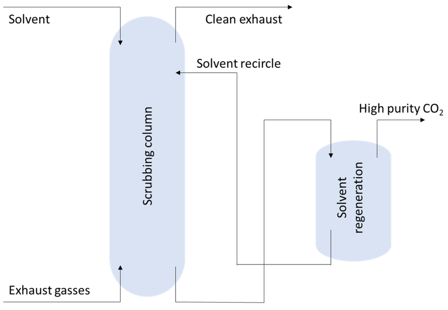
2.1. Solvent Scrubbing
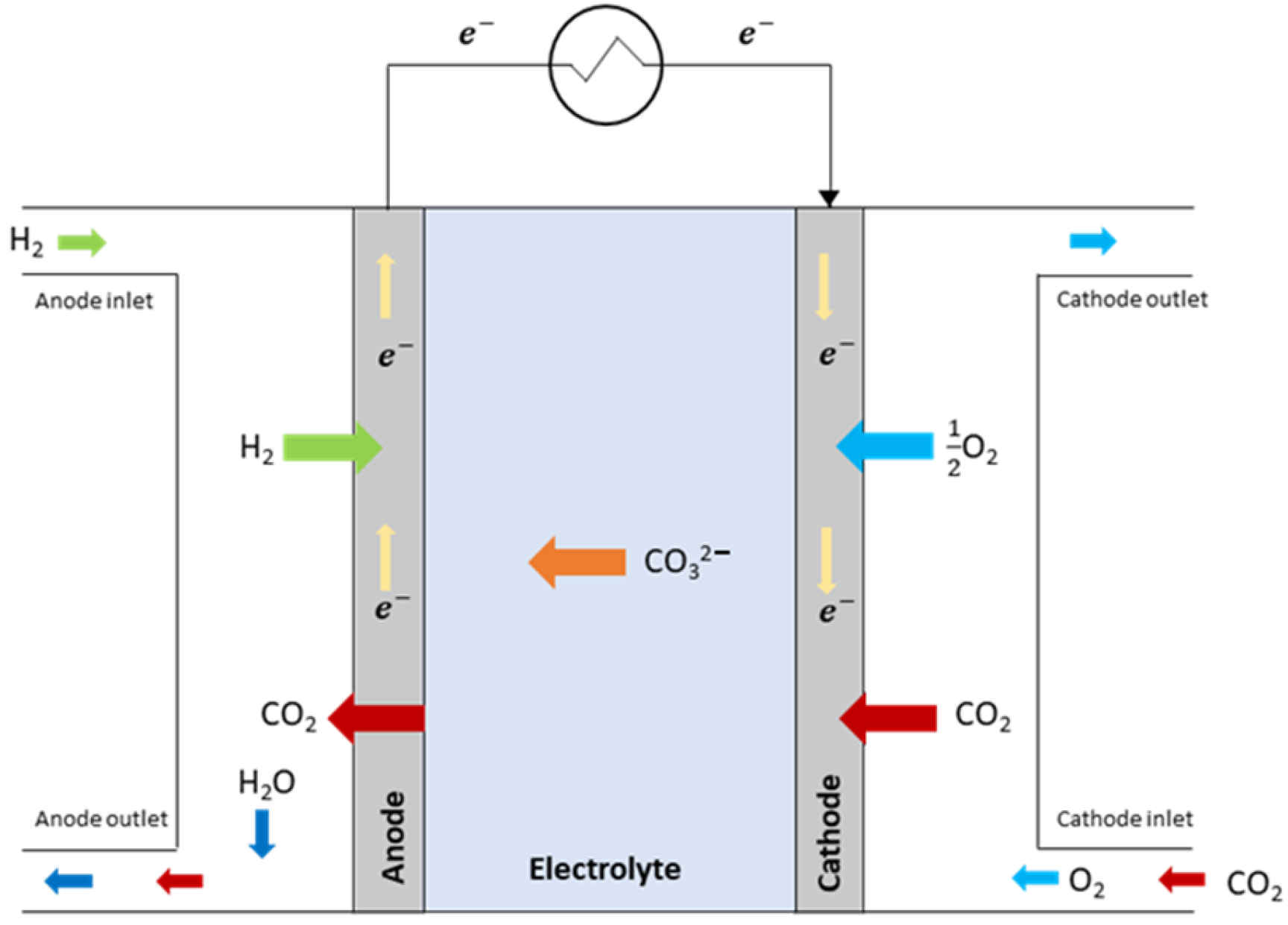
2.2. Molten Carbonate Fuel Cells
2.3. Calcium Hydroxide to Limestone Reaction
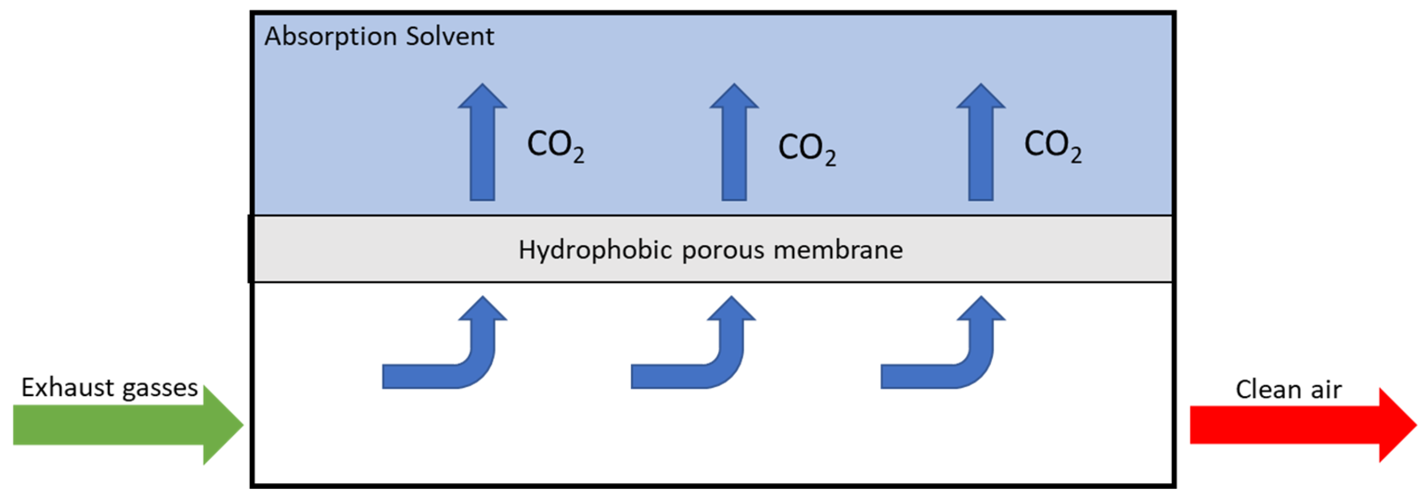
2.4. Membrane
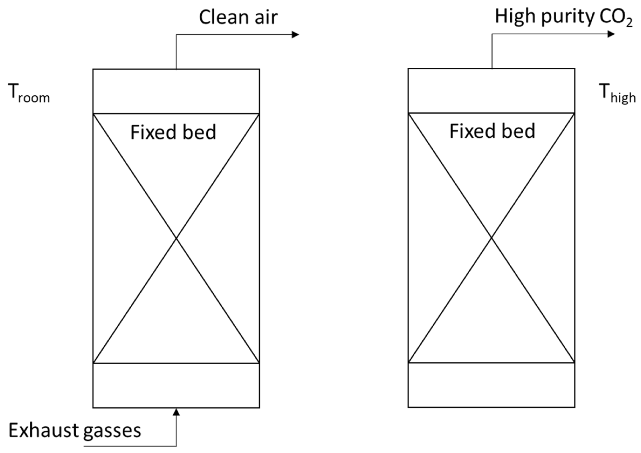
2.5. Fixed Bed Adsorption and Desorption
2.6. Ionic Liquids
3. Discussion of the Results
- Route length: The longer the route is, the more complex the technology implementation is, in terms of reagents or CO2 to be stored, driving the dimension of the equipment.
- Route-planning: Having a fixed trading scheme facilitates the logistics for the reagents or CO2 supply and handling while unplanned voyages make it more complex, especially if trading is carried out in remote locations as typically happens for merchant vessels.
- Space availability: Space is one of the main challenges, especially talking about retrofit. Optimize the performances is always one of the main topics during the development of a new technology, but space constraints are indubitably impacting on the possibility of installing a system on board a ship. Even if for certain ships the available space could be considered more or easier to be used, the loss of cargo capacity must be considered and the trade-off carefully evaluated.
- Maintenance: The impact that maintenance has cannot be considered as much as others but is still worth evaluating. Maintenance is to be considered not merely in terms of cost for it but also in terms of personnel capability and availability and passenger ships are typically better structured then others in this aspect.
- Reagent/fuel transportation capability: Similarly to space availability, this factor can have a huge impact depending on the ship type. However, the weight this factor has varies among the different technologies depending on the actual necessity of carrying reagents or fuel in big quantities.
- Public opinion: It is worth considering the public opinion on the evaluation, even if with minimal impact, being an important driver for shipowners, especially for passenger ships. Some technologies can be seen more environmentally friendly or more advanced than others, resulting in being more appealing for public opinion.
- Technology cost: Seen mainly as the capex for the technology implementation, this can be a driver for certain maritime segments (cost of the technology implementation compared with the ship value).
- Levelized capturing cost: This is indubitably one of the main drivers for the technology implementation. This parameter considers capex, opex, amortization, additional income or expenditures from CO2 handling, carbon taxes or credits over the remaining ship-lifetime period and allows us to better compare the different technologies with the most objective analysis.
4. Conclusions
- -
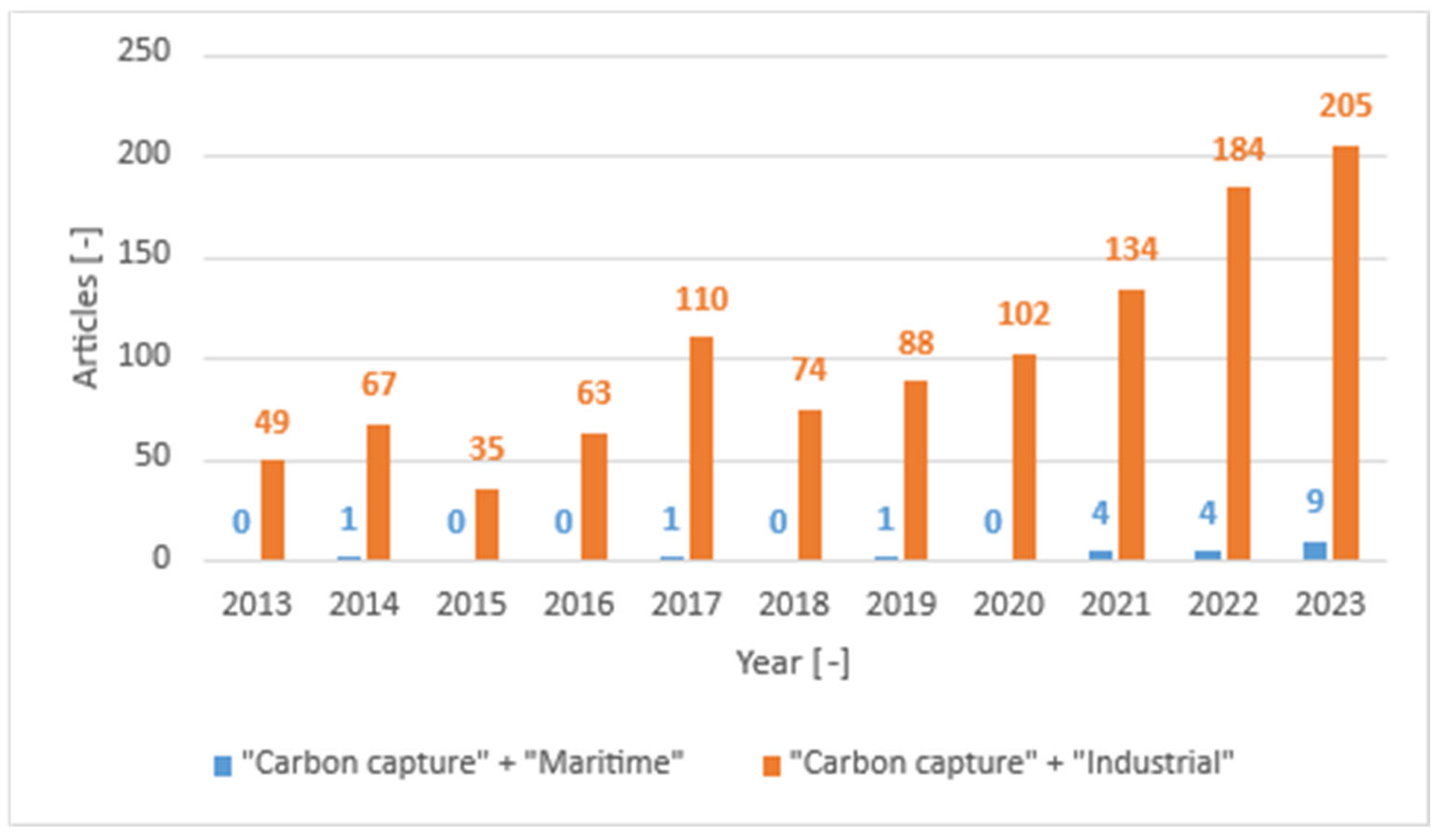
- Research in this field is still without real applications, but is attracting increasing attention;
- -
- There are numerous possible CCS technologies that have already been tested on land and appear promising on board;
- -
- There are some intrinsic limitations to the on-board environment for system installations, mainly related to space and safety;
- -
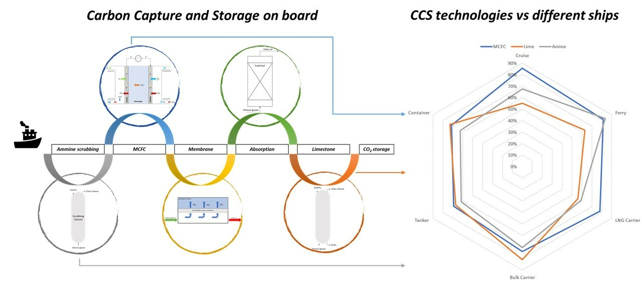
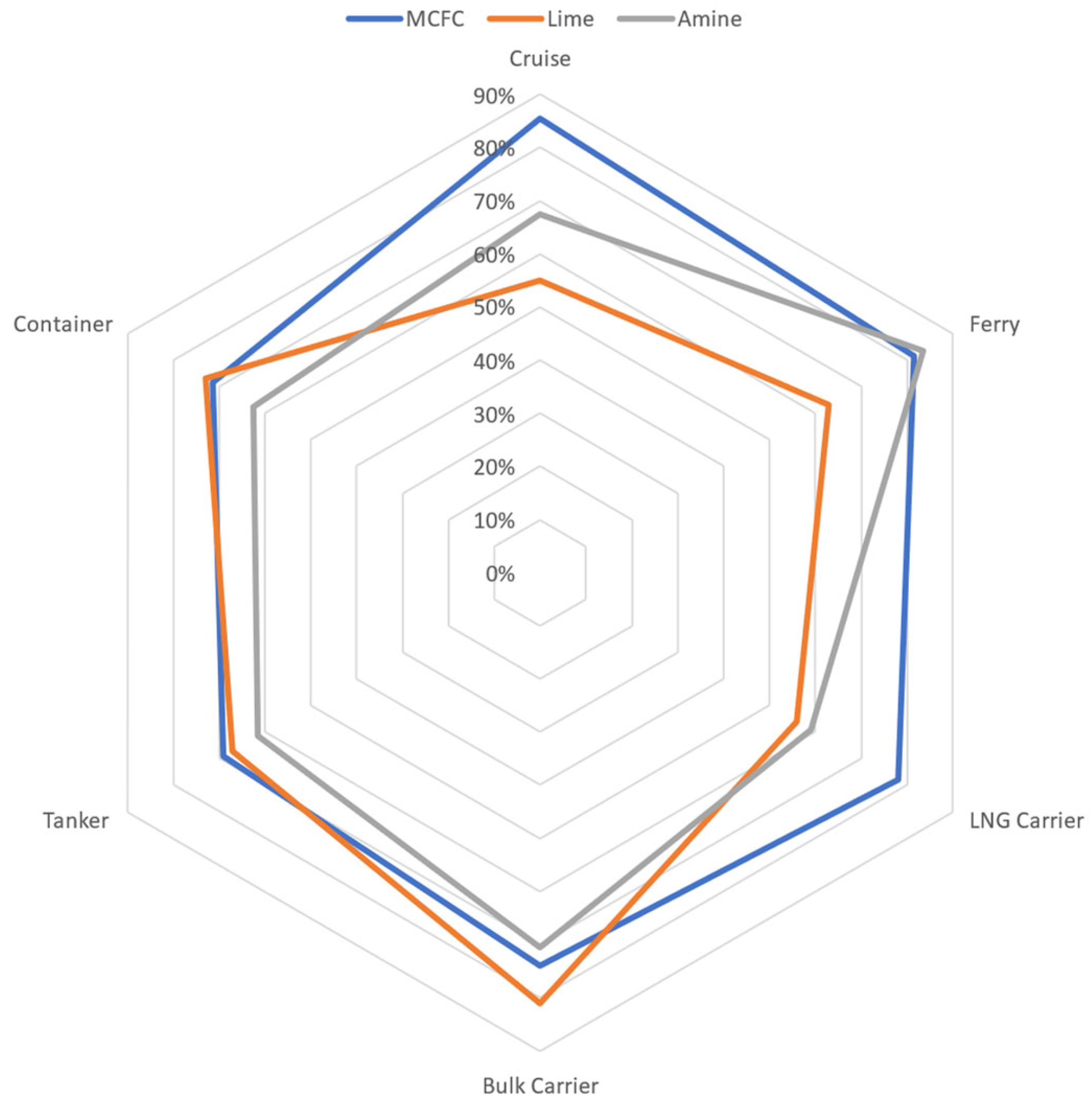
- The choice of the appropriate CCS systems on board depends on the type of vessel;
- -
- Molten Carbonate Fuel Cells could be applied satisfactorily on all ships, but amines would be preferable for ferries and lime for cargoes.
5. Future Work
Author Contributions
Funding
Data Availability Statement
Conflicts of Interest
Abbreviations
| CCS | Carbon Capture and Storage |
| DIPA | DiIsoPropanolAmine |
| DEA | DiEthanolAmine |
| EEDI | Energy Efficiency Design Index |
| EEXI | Energy Efficiency Existing Ship Index |
| ETS | Emission Trading Scheme |
| GWP | Global Warming Potential |
| ICE | Internal Combustion Engines |
| IMO | International Maritime Organisation |
| LNG | Liquefied Natural Gas |
| KPI | Key Performance Indicator |
| MC | Membrane Contactor |
| MDEA | Methyl DiEthanolAmine |
| MEA | MonoEthanolAmine |
| MGS | Membrane Gas Separator |
| OCCS | On-board Carbon Capture and Storage |
| TEA | TriEthanolAmine |
| TRL | Technology Readiness Level |
| TSILs | Task Specific Ionic Liquids |
Appendix A

| Vessel | Route-Length | Route-Planning | Space Availability | Available Personal | Reagent/Fuel Transportation Capability | Public Opinion | Technology Cost | Levelized Capturing Cost | |||||||||||||||||
|---|---|---|---|---|---|---|---|---|---|---|---|---|---|---|---|---|---|---|---|---|---|---|---|---|---|
| 1–2 Days | 1 Week | 2 Weeks or More | Fixed Routes | Planned in Advance | Not Planned | Space Available w/o Cargo Loss | Space Available w/ Cargo Loss | Little Space Available | Crew Available | Mid Crew Available | Little Crew Available | Space Available w/o Cargo Loss | Space Available w/ Cargo Loss | Little Space Available | Good | Neutral | Bad | Expensive Ship | Mid-Level Ship | Cheap Ship | High | Mid | Low | ||
| Cruise | MCFC | X | X | X | X | X | X | X | X | ||||||||||||||||
| Limestone | X | X | X | X | X | X | X | X | |||||||||||||||||
| Amine | X | X | X | X | X | X | X | X | |||||||||||||||||
| Ferry | MCFC | X | X | X | X | X | X | X | X | ||||||||||||||||
| Limestone | X | X | X | X | X | X | X | X | |||||||||||||||||
| Amine | X | X | X | X | X | X | X | X | |||||||||||||||||
| LNG Carrier | MCFC | X | X | X | X | X | X | X | X | ||||||||||||||||
| Limestone | X | X | X | X | X | X | X | X | |||||||||||||||||
| Amine | X | X | X | X | X | X | X | X | |||||||||||||||||
| Bulk Carrier | MCFC | X | X | X | X | X | X | X | X | ||||||||||||||||
| Limestone | X | X | X | X | X | X | X | X | |||||||||||||||||
| Amine | X | X | X | X | X | X | X | X | |||||||||||||||||
| Tanker | MCFC | X | X | X | X | X | X | X | X | ||||||||||||||||
| Limestone | X | X | X | X | X | X | X | X | |||||||||||||||||
| Amine | X | X | X | X | X | X | X | X | |||||||||||||||||
| Container | MCFC | X | X | X | X | X | X | X | X | ||||||||||||||||
| Limestone | X | X | X | X | X | X | X | X | |||||||||||||||||
| Amine | X | X | X | X | X | X | X | X | |||||||||||||||||
References
- Scheffer, M.; Brovkin, V.; Cox, M. Positive feedback between global warming and atmospheric CO2 concentration inferred from past climate change. Geophys. Res. Lett. 2006, 33, 1–4. [Google Scholar] [CrossRef]
- Arnell, N.W.; Cannell, M.G.; Hulme, M.; Kovats, R.S.; Mitchell, J.F.; Nicholls, R.J.; Parry, M.L.; Livermore, M.T. The Consequences of CO2 Stabilisation for the Impacts of Climate Change. Clim. Change 2002, 53, 413–446. [Google Scholar] [CrossRef]
- Crippa, M.; Guizzardi, D.; Banja, M.; Solazzo, E.; Muntean, M.; Schaaf, E.; Pagani, F.; Monforti-Ferrario, F.; Olivier, J.G.; Quadrelli, R. CO2 Emissions of All World Countries. JRC Science of Policy Report; European Commission: Brussels, Belgium, 2022. [Google Scholar] [CrossRef]
- Pathak, M.; Slade, R.; Shukla, P.R.; Skea, J.; Pichs-Madruga, R.; Urge-Vorsat, D. WG III Contribution to the Sixth Assessment Report; IPCC: Geneva, Switzerland, 2022. [Google Scholar]
- Friedlingstein, P.; Jones, M.W.; O’Sullivan, M.; Andrew, R.M.; Bakker, D.C.; Hauck, J.; Le Quéré, C.; Peters, G.P.; Peters, W.; Pongratz, J. Global Carbon Budget. Earth Syst. Sci. Data 2022, 14, 4811–4900. [Google Scholar] [CrossRef]
- Longa, F.D.; Detz, R.; van der Zwaan, B. Integrated assessment projections for the impact of innovation on CCS deployment in Europe. Int. J. Greenh. Gas Control 2020, 103, 103–133. [Google Scholar]
- Fiorini, A.; Pasimeni, F.; Georgakaki, A.; Tzimas, E. Analysis of the European CCS Research and Innovation Landscape. Energy Procedia 2017, 114, 7651–7658. [Google Scholar] [CrossRef]
- Størset, S.Ø.; Tangen, G.; Berstad, D.; Eliasson, P.; Hoff, K.A.; Langørgen, Ø.; Munkejord, S.T.; Roussanaly, S.; Torsæter, M. Profiting from CCS innovations: A study to measure potential value creation from CCS research and development. Int. J. Greenh. Gas Control 2019, 83, 208–215. [Google Scholar] [CrossRef]
- IMO. IMO Strategy on Reduction of GHG Emission from Ships. Available online: http://www.imo.org (accessed on 3 January 2023).
- Comer, B.; Chen, C.; Rutherford, D. Relating Short-Term Measures to IMO’s Minimum 2050 Emissions Reduction Target; Emissions Reduction Target; International Council on Clean Transportation. 2018. Available online: https://theicct.org/publication/relating-short-term-measures-to-imos-minimum-2050-emissions-reduction-target/ (accessed on 13 May 2023).
- Joung, T.H.; Kang, S.G.; Lee, J.K.; Ahn, J. The IMO initial strategy for reducing Greenhouse Gas (GHG) emissions, and its follow-up actions towards 2050. J. Int. Marit. Saf. Environ. Aff. Shipp. 2020, 4, 1–7. [Google Scholar] [CrossRef]
- Rutherford, D.; Mao, X.; Comer, B. Potential CO2 reductions under the Energy Efficiency Existing Ship Index. Int. Counc. Clean. Transp. 2020, 222, 1–12. Available online: https://theicct.org/publication/potential-co2-reductions-under-the-energy-efficiency-existing-ship-index/ (accessed on 23 April 2023).
- United Nation Climate Change. Emissions from Fuel Used for International Aviation and Maritime Transport. Available online: https://unfccc.int/ (accessed on 4 January 2023).
- Chuah, L.F.; Mokhtar, K.; Ruslan, S.M.; Bakar, A.A.; Abdullah, M.A.; Osman, N.H.; Bokhari, A.; Mubashir, M.; Show, P.L. Implementation of the energy efficiency existing ship index and carbon intensity indicator on domestic ship for marine environmental protection. Environ. Res. 2023, 222, 115–348. [Google Scholar] [CrossRef] [PubMed]
- Fedi, L. The monitoring, reporting and verification of ships’ carbon dioxide emissions: A European substantial policy measure towards accurate and transparent carbon dioxide quantification. Ocean Yearbook. Online 2017, 31, 381–417. [Google Scholar] [CrossRef]
- Cariou, P.; Lindstad, E.; Jia, H. The impact of an EU maritime emissions trading system on oil trades. Transp. Res. Part D Transp. Environ. 2021, 99, 102992. [Google Scholar] [CrossRef]
- Ordinary Legislative Procedure. Interinstitutional Negotiations-ETS. Available online: https://www.europarl.europa.eu/ (accessed on 4 January 2023).
- EU ETS. Available online: https://climate.ec.europa.eu/eu-action/eu-emissions-trading-system-eu-ets_en (accessed on 2 January 2023).
- Levander, O. New concepts in ferry propulsion. Wärtsilä Technol. J. 2007, pp. 45–50. Available online: http://www.123seminarsonly.com/Seminar-Reports/020/44752818-Ferry-Propulsion-New-Concept.pdf (accessed on 2 March 2023).
- Ling-Chin, J.; Roskilly, A. Investigating the implications of a new-build hybrid power system for Roll-on/Roll-off cargo ships from a sustainability perspective—A life cycle assessment case study. Appl. Energy 2016, 181, 416–434. [Google Scholar] [CrossRef]
- Bengtsson, S.; Andersson, K.; Fridell, E. A comparative life cycle assessment of marine fuels: Liquefied natural gas and three other fossil fuels. J. Eng. Marit. Environ. 2011, 225, 97–110. [Google Scholar] [CrossRef]
- Chiong, M.C.; Kang, H.S.; Shaharuddin, N.M.; Mat, S.; Quen, L.K.; Ten, K.H.; Ong, M.C. Challenges and opportunities of marine propulsion with alternative fuels. Renew. Sustain. Energy Rev. 2021, 149, 111–397. [Google Scholar] [CrossRef]
- Gabiña, G.; Martin, L.; Basurko, O.C.; Clemente, M.; Aldekoa, S.; Uriondo, Z. Waste oil-based alternative fuels for marine diesel engines. Fuel Process. Technol. 2016, 153, 28–36. [Google Scholar] [CrossRef]
- Paulauskiene, T.; Bucas, M.; Laukinaite, A. Alternative fuels for marine applications: Biomethanol-biodiesel-diesel blends. Fuel 2019, 248, 161–167. [Google Scholar] [CrossRef]
- Law, L.C.; Mastorakos, E.; Evans, S. Estimates of the Decarbonization Potential of Alternative Fuels for Shipping as a Function of Vessel Type, Cargo, and Voyage. Energies 2022, 15, 7468. [Google Scholar] [CrossRef]
- Shu, G.; Liang, Y.; Wei, H.; Tian, H.; Zhao, J.; Liu, L. A review of waste heat recovery on two-stroke IC engine aboard ships. Renew. Sustain. Energy Rev. 2013, 19, 385–401. [Google Scholar] [CrossRef]
- Zhu, S.; Zhang, K.; Deng, K. A review of waste heat recovery from the marine engine with highly efficient bottoming power cycles. Renew. Sustain. Energy Rev. 2020, 120, 109–611. [Google Scholar] [CrossRef]
- IEA. CO2 Capture and Storage: A Key Carbon Abatement Option; IEA: Paris, France, 2008. [Google Scholar]
- NETL. Carbon Sequestration Technology Roadmap and Program Plan 2007, Ensuring the Future of Fossil Energy Systems through the Successful Deployment of Carbon Capture and Storage Technologies; NETL: Albany, OR, USA, 2007; Available online: http://cepac.cheme.cmu.edu/pasi2008/slides/siirola/library/reading/2007Roadmap.pdf (accessed on 31 August 2023).
- García-Mariaca, A.; Llera-Sastresa, E. Review on carbon capture in ice driven transport. Energies 2021, 14, 6865. [Google Scholar] [CrossRef]
- Maelum, M.; Mathisen, A.; Jayarathna, C.; Skagestad, R.; Belgaroui, J.; Dijkhuizen, C. Ship-Based CO2 Capture–Port Integration. In Proceedings of the 16th International Conference on Greenhouse Gas Control Technologies, Lyon, France, 23–27 October 2022. [Google Scholar]
- EverLong. Available online: https://everlongccus.eu/about-the-project (accessed on 21 August 2023).
- Carbon Capture, Storage and Utilization. Available online: https://energy.ec.europa.eu/topics/oil-gas-and-coal/carbon-capture-storage-and-utilisation_en (accessed on 21 July 2023).
- ENI. Cattura, Stoccaggio e Riutilizzo della CO2 (CCUS). Available online: https://www.eni.com/it-IT/attivita/gestione-anidride-carbonica.html (accessed on 25 August 2023).
- Carbon Capture and Storage (CCS) in Italy. Available online: https://ocre-geoscience.com/carbon-capture-and-storage-ccs-in-italy/ (accessed on 6 June 2023).
- Su, D.; Herraiz, L.; Lucquiaud, M.; Thomson, C.; Chalmers, H. Thermal integration of waste to energy plants with Post-combustion CO2 capture. Fuel 2023, 332, 126004. [Google Scholar] [CrossRef]
- Al Baroudi, H.; Awoyomi, A.; Patchigolla, K.; Jonnalagadda, K.; Anthony, E.J. A review of large-scale CO2 shipping and marine emissions management for carbon capture, utilization and storage. Appl. Energy 2021, 287, 116510. [Google Scholar] [CrossRef]
- Global CCS Institute. Knowledge Sharing Report. CO2 Liquid Logistics Shipping Concept (LLSC): Overall Supply Chain Optimization; Global CCS Institute: Melbourne, Australia, 2011; Available online: https://www.globalccsinstitute.com/resources/publications-reports-research/knowledge-sharing-report-co2-liquid-logistics-shipping-concept-llsc-overall-supply-chain-optimization/ (accessed on 7 July 2023).
- Ren, B.; Xu, Y.; Huang, Y.W.; She, C.; Sun, B. Methanol production from natural gas reforming and CO2 capturing process, simulation, design, and technical-economic analysis. Energy 2023, 263, 125–879. [Google Scholar] [CrossRef]
- Hidalgo, D.; Martín-Marroquín, J.M. Power-to-methane, coupling CO2 capture with fuel production: An overview. Renew. Sustain. Energy Rev. 2020, 132, 110057. [Google Scholar] [CrossRef]
- Fang, S.; Xu, Y.; Li, Z.; Ding, Z.; Liu, L.; Wang, H. Optimal Sizing of Shipboard Carbon Capture System for Maritime Greenhouse Emission Control. IEEE Trans. Ind. Appl. Inst. Electr. Electron. Eng. Inc. 2019, 55, 5543–5553. [Google Scholar] [CrossRef]
- NETL. Carbon Dioxide Capture Handbook; NETL: Albany, OR, USA, 2015. Available online: https://netl.doe.gov/sites/default/files/netl-file/Carbon-Dioxide-Capture-Handbook-2015.pdf (accessed on 4 June 2023).
- EverLong. Available online: https://everlongccus.eu/work-packages/work-package-2 (accessed on 17 August 2023).
- Emis. Scrubbing Definition. Available online: https://emis.vito.be/en/bat/tools-overview/sheets/gas-scrubbing-general#:~:text=A%20scrubber%20is%20a%20waste,technique%20for%20many%20gaseous%20emissions (accessed on 21 December 2022).
- Haszeldine, R.S. Carbon capture and storage: How green can black be? Science 2009, 325, 1647–1652. [Google Scholar] [CrossRef] [PubMed]
- Smith, N.; Miller, G.; Aandi, I.; Gadsden, R.; Davison, J. Performance and Costs of CO2 Capture at Gas Fired Power Plants. Energy Procedia 2013, 37, 2443–2452. [Google Scholar] [CrossRef]
- Agbonghae, E.O.; Hughes, K.J.; Ingham, D.B.; Ma, L.; Pourkashanian, M. Optimal process design of commercial-scale amine-based CO2 capture plants. Ind. Eng. Chem. Res. 2014, 53, 14815–14829. [Google Scholar] [CrossRef]
- Luo, X.; Wang, M. Study of solvent-based carbon capture for cargo ships through process modeling and simulation. Appl. Energy 2017, 195, 402–413. [Google Scholar] [CrossRef]
- Lin, Y.J.; Rochelle, G.T. Approaching a reversible stripping process for CO2 capture. Chem. Eng. J. 2016, 283, 1033–1043. [Google Scholar] [CrossRef]
- Liang, Z.H.; Rongwong, W.; Liu, H.; Fu, K.; Gao, H.; Cao, F.; Zhang, R.; Sema, T.; Henni, A.; Sumon, K.; et al. Recent progress and new developments in post-combustion carbon-capture technology with amine-based solvents. Int. J. Greenh. Gas Control 2015, 40, 26–54. [Google Scholar] [CrossRef]
- Haghtalab, A.; Eghbali, H.; Shojaeian, A. Experiment and modeling solubility of CO2 in aqueous solutions of Diisopropanolamine + 2-amino-2-methyl-1-propanol + Piperazine at high pressures. J. Chem. Thermodyn. 2014, 71, 71–83. [Google Scholar] [CrossRef]
- Ji, C.; Yuan, S.; Huffman, M.; El-Halwagi, M.M.; Wang, Q. Post-combustion carbon capture for tank to propeller via process modeling and simulation. J. CO2 Util. 2021, 51, 101655. [Google Scholar] [CrossRef]
- Wehrung, Q.; Destefanis, E.; Caviglia, C.; Bernasconi, D.; Pastero, L.; Bruno, M.; Bernasconi, A.; Magnetti Vernai, A.; Di Rienzo, A.; Pavese, A. Experimental Modeling of CO2 Sorption/Desorption Cycle with MDEA/PZ Blend: Kinetics and Regeneration Temperature; Università di Torino: Turin, Italy, 2023; status (submitted). [Google Scholar]
- Jung, J.; Jeong, Y.S.; Lim, Y.; Lee, C.S.; Han, C. Advanced CO2 capture process using MEA scrubbing: Configuration of a split flow and phase separation heat exchanger. Energy Procedia 2013, 37, 1778–1784. [Google Scholar] [CrossRef]
- Arstad, B.; Blom, R.; Swang, O. CO2 absorption in aqueous solutions of alkanolamines: Mechanistic insight from quantum chemical calculations. J. Phys. Chem. A 2007, 111, 1222–1228. [Google Scholar] [CrossRef]
- Da Silva, E.F.; Svendsen, H.F. Ab initio study of the reaction of carbamate formation from CO2 and alkanolamines. Ind. Eng. Chem. Res. 2004, 43, 3413–3418. [Google Scholar] [CrossRef]
- Xie, H.B.; Zhou, Y.; Zhang, Y.; Johnson, J.K. Reaction mechanism of monoethanolamine with CO2 in aqueous solution from molecular modelling. J. Phys. Chem. A 2010, 114, 11844–11852. [Google Scholar] [CrossRef] [PubMed]
- Danckwerts, P.V. The reaction of CO2 with ethanolamines. Chem. Eng. Sci. 1979, 34, 443–446. [Google Scholar] [CrossRef]
- Lv, B.; Guo, B.; Zhou, Z.; Jing, G. Mechanisms of CO2 Capture into Monoethanolamine Solution with Different CO2 Loading during the Absorption/Desorption Processes. Environ. Sci. Technol. 2015, 49, 10728–10735. [Google Scholar] [CrossRef] [PubMed]
- Wang, Z.; Fang, M.; Pan, Y.; Yan, S.; Luo, Z. Amine-based absorbents selection for CO2 membrane vacuum regeneration technology by combined absorption-desorption analysis. Chem. Eng. Sci. 2013, 93, 238–249. [Google Scholar] [CrossRef]
- Oh, S.Y.; Binns, M.; Cho, H.; Kim, J.K. Energy minimization of MEA-based CO2 capture process. Appl. Energy 2016, 169, 353–362. [Google Scholar] [CrossRef]
- Liu, J.; Wang, S.; Zhao, B.; Tong, H.; Chen, C. Absorption of carbon dioxide in aqueous ammonia. Energy Procedia 2009, 1, 933–940. [Google Scholar] [CrossRef]
- Zhang, M.; Guo, Y. Analysis on Regeneration Energy of NH3-based CO2 Capture with Equilibrium-based Simulation Method. Energy Procedia 2017, 114, 1480–1487. [Google Scholar] [CrossRef]
- Chung, W.; Roh, K.; Lee, J.H. Design and evaluation of CO2 capture plants for the steelmaking industry by means of amine scrubbing and membrane separation. Int. J. Greenh. Gas Control 2018, 74, 259–270. [Google Scholar] [CrossRef]
- Van den Akker, J.T. Carbon Capture Onboard LNG-Fueled Vessels: A Feasibility Study. Master’s Thesis, Delft University of Technology, Delft, The Netherlands, 2 October 2017. Available online: https://repository.tudelft.nl/islandora/object/uuid:a94741f3-c7cb-4970-80d1-bceebff4e423?collection=education (accessed on 31 August 2023).
- Awoyomi, A.; Patchigolla, K.; Anthony, E.J. CO2/SO2 emission reduction in CO2 shipping infrastructure. Int. J. Greenh. Gas Control 2019, 88, 57–70. [Google Scholar] [CrossRef]
- Awoyomi, A.; Patchigolla, K.; Anthony, E.J. Process and economic evaluation of an onboard capture system for LNG-fueled CO2 carriers. Ind. Eng. Chem. Res. 2020, 59, 6951–6960. [Google Scholar] [CrossRef]
- Lee, S.; Yoo, S.; Park, H.; Ahn, J.; Chang, D. Novel methodology for EEDI calculation considering onboard carbon capture and storage system. Int. J. Greenh. Gas Control 2021, 105, 103241. [Google Scholar] [CrossRef]
- Asimakopoulou, A. MemCCSea: Carbon Capture at Sea Project Concept & Key Objective; CATO: Rotterdam, The Netherlands, 2022; Available online: https://www.co2-cato.org/cato-download/5823/20220623_160651_MemCCSea.pdf (accessed on 19 June 2023).
- Mastropasqua, L.; Pierangelo, L.; Spinelli, M.; Romano, M.C.; Campanari, S.; Consonni, S. Molten carbonate fuel cells retrofits for CO2 capture and enhanced energy production in the steel industry. Int. J. Greenh. Gas Control 2019, 88, 195–208. [Google Scholar] [CrossRef]
- Campanari, S.; Chiesa, P.; Manzolini, G.; Giannotti, A.; Federici, F.; Bedont, P.; Parodi, F. Application of MCFCs for active CO2 capture within natural gas combined cycles. Energy Procedia 2011, 4, 1235–1242. [Google Scholar] [CrossRef]
- Carapellucci, R.; di Battista, D.; Cipollone, R. The retrofitting of a coal-fired subcritical steam power plant for carbon dioxide capture: A comparison between MCFC-based active systems and conventional MEA. Energy Convers. Manag. 2019, 194, 124–139. [Google Scholar] [CrossRef]
- Archetti, M.; Audasso, E.; Bosio, B.; Bove, D. High temperature fuel cells to reduce CO2 emission in the maritime sector. E3S Web Conf. 2022, 334, 1–8. [Google Scholar] [CrossRef]
- Barckholtz, T.A.; Taylor, K.M.; Narayanan, S.; Jolly, S.; Ghezel-Ayagh, H. Molten carbonate fuel cells for simultaneous CO2 capture, power generation, and H2 generation. Appl. Energy 2022, 313, 118553. [Google Scholar] [CrossRef]
- Campari, S.; Manzolini, G.; Chiesa, P. Using MCFC for high efficiency CO2 capture from natural gas combined cycles: Comparison of internal and external reforming. Appl. Energy 2013, 112, 772–783. [Google Scholar] [CrossRef]
- Audasso, E.; Kim, K.; Accardo, G.; Sung, K.H.; Yoon, P.S. Investigation of molten carbonate electrolysis cells performance for H2 production and CO2 capture. J. Power Sources 2022, 523, 231039. [Google Scholar] [CrossRef]
- Rexed, I. Applications for Molten Carbonate Fuel Cells; KTH Royal Institute of Technology, School of Chemical Science and Engineering: Stockholm, Sweden, 2014. [Google Scholar]
- Perez-Trujillo, J.P.; Elizalde-Blancas, F.; Della Pietra, M.; McPhail, S.J. A numerical and experimental comparison of a single reversible molten carbonate cell operating in fuel cell mode and electrolysis mode. Appl. Energy 2018, 226, 1037–1055. [Google Scholar] [CrossRef]
- Audasso, E.; Bosio, B.; Bove, D.; Arato, E.; Barckholtz, T.; Kiss, G.; Rosen, J.; Elsen, H.; Gutierrez, R.B.; Han, L. New, Dual-Anion Mechanism for Molten Carbonate Fuel Cells Working as Carbon Capture Devices. J. Electrochem. Soc. 2020, 167, 8. [Google Scholar] [CrossRef]
- Audasso, E.; Bosio, B.; Bove, D.; Arato, E.; Barckholtz, T.; Kiss, G.; Rosen, J.; Elsen, H.; Gutierrez, R.B.; Han, L. The Effects of Gas Diffusion in Molten Carbonate Fuel Cells Working as Carbon Capture Devices. J. Electrochem. Soc. 2020, 167, 11. [Google Scholar] [CrossRef]
- Morita, H.; Kawase, M.; Mugikura, Y. AsaDegradation mechanism of molten carbonate fuel cell based on long-term performance: Long-term operation by using bench-scale cell and post-test analysis of the cell. J. Power Sources 2010, 195, 6988–6996. [Google Scholar] [CrossRef]
- Barckholtz, T.; Elsen, H.; Kalamaras; Kiss, G.; Rosen, J.; Bove, D.; Audasso, E.; Bosio, B. Experimental and Modeling Investigation of CO3−−/OH− Equilibrium Effects on Molten Carbonate Fuel Cell Performance in Carbon Capture Applications. Frontiers 2021, 9, 669761. [Google Scholar] [CrossRef]
- Bove, D.; Audasso, E.; Barckholtz, T.; Kiss, G.; Rosen, J.; Bosio, B. Process analysis of molten carbonate fuel cells in carbon capture applications. Int. J. Hydrog. Energy 2021, 46, 15032–15045. [Google Scholar] [CrossRef]
- Rosen, J.; Geary, T.; Hilmi, A.; Blanco-Gutierrez, R.; Yuh, C.Y.; Pereira, C.S.; Han, L.; Johnson, R.A.; Willman, C.A.; Ghezel-Ayagh, H. Molten Carbonate Fuel Cell Performance for CO2 Capture from Natural Gas Combined Cycle Flue Gas. J. Electrochem. Soc. 2020, 167, 6. [Google Scholar] [CrossRef]
- Boudouard Equilibrium. Available online: https://www.giessereilexikon.com/en/foundry-lexicon/Encyclopedia/show/boudouard-equilibrium-4705/?cHash=e172a61ebbc38ae84221e9903d5ec7a4 (accessed on 21 December 2022).
- Randstro, S. New Materials for the Molten Carbonate Fuel Cell. Ph.D. Thesis, KTH, School of Chemical Science and Engineering (CHE), Chemical Engineering and Technology, Applied Electrochemistry, Stockholm, Sweden, 2008. Available online: https://www.diva-portal.org/smash/get/diva2:13180/FULLTEXT01.pdf (accessed on 16 May 2023).
- Bosio, B.; Archetti, M.; Audasso, E.; Bove, D. Process analysis of a molten carbonate fuel cell on-board application to reduce vessel CO2 emissions. Chem. Eng. Process. Process Intensif. 2023, 190, 109415. [Google Scholar] [CrossRef]
- Abohamzeh, E.; Salehi, F.; Sheikholeslami, M.; Abbassi, R.; Khan, F. Review of hydrogen safety during storage, transmission, and applications processes. J. Loss Prev. Process Ind. 2021, 72, 104569. [Google Scholar] [CrossRef]
- Takahashi, T.; Kawabata, M.; Yoshida, A.; Kai, T.; Kimura, H.; Inoue, A. Methanol Steam Reforming over Copper Catalyst Prepared from Amorphous Cu-Zr Alloy with Minute Amounts of Noble Metals. Stud. Surf. Sci. Catal. 2007, 172, 293–296. [Google Scholar]
- Office of Energy Efficiency & Renewable Energy. Methane Reforming. Available online: https://www.energy.gov/eere/fuelcells/hydrogen-production-natural-gas-reforming (accessed on 2 January 2023).
- Della Pietra, M.; Discepoli, G.; Bosio, B.; McPhail, S.J.; Barelli, L.; Bidini, G.; Ribes-Greus, A. Experimental investigation of SO2 poisoning in a Molten Carbonate Fuel Cell operating in CCS configuration. Int. J. Hydrog. Energy 2016, 41, 18822–18836. [Google Scholar] [CrossRef]
- Ship Technology. Viking Lady. Available online: https://www.ship-technology.com/projects/viking-lady/ (accessed on 11 January 2023).
- Inal, O.B.; Deniz, C. Emission Analysis of LNG Fuelled Molten Carbonate Fuel Cell System for a Chemical Tanker Ship: A Case Study. Mar. Sci. Technol. Bull. 2020, 10, 118–133. [Google Scholar] [CrossRef]
- Han, S.J.; Yoo, M.; Kim, D.W.; Wee, J.H. Carbon dioxide capture using calcium hydroxide aqueous solution as the absorbent. Energy Fuels 2011, 25, 3825–3834. [Google Scholar] [CrossRef]
- Costagliola, M.A.; Prati, M.V.; Perretta, G. Post combustion CO2 capture with calcium and lithium hydroxide. Sci. Rep. 2022, 12, 10518. [Google Scholar] [CrossRef]
- Caserini, S.; Pagano, D.; Campo, F.; Abbà, A.; De Marco, S.; Righi, D.; Renforth, P.; Grosso, M. Potential of Maritime Transport for Ocean Liming and Atmospheric CO2 Removal. Front. Clim. 2021, 3, 575900. [Google Scholar] [CrossRef]
- Archetti, M.; Bosio, B. Road to maritime sector decarbonization. In Technology and Science for the Ship of the Future; Rizzuto, E., Ruggiero, V., Eds.; IOS Press: Amsterdam, The Netherlands, 2022. [Google Scholar] [CrossRef]
- Harvey, L.D.D. Mitigating the atmospheric CO2 increase and ocean acidification by adding limestone powder to upwelling regions. J. Geophys. Res. Ocean. 2008, 113, 4. [Google Scholar] [CrossRef]
- Zhou, P.; Wang, H. Carbon capture and storage-Solidification and storage of carbon dioxide captured on ships. Ocean Eng. 2014, 91, 172–180. [Google Scholar] [CrossRef]
- Ecospray Technologies S.R.L. Internal Technical Report, Carbon Capture with Calcium Hydroxide; Ecospray Technologies S.R.L.: Alzano Scrivia, Italy, 2023. [Google Scholar]
- Foteinis, S.; Andresen, J.; Campo, F.; Caserini, S.; Renforth, P. Life cycle assessment of ocean liming for carbon dioxide removal from the atmosphere. J. Clean. Prod. 2022, 370, 133309. [Google Scholar] [CrossRef]
- Limestone to Calcium Hydroxide. Available online: https://chem.libretexts.org/Bookshelves/Inorganic_Chemistry/Supplemental_Modules_and_Websites_(Inorganic_Chemistry)/Descriptive_Chemistry/Elements_Organized_by_Block/1_s-Block_Elements/Group__2_Elements%3A_The_Alkaline_Earth_Metals/Z020_Chemistry_of_Calcium_(Z20)/Calcium_Hydroxide (accessed on 25 June 2023).
- Limestone and Calcium Oxide. Available online: https://www.essentialchemicalindustry.org/chemicals/calcium-carbonate.html (accessed on 3 July 2023).
- Oh, J.; Anantharaman, R.; Zahid, U.; Lee, P.S.; Lim, Y. Process design of onboard membrane carbon capture and liquefaction systems for LNG-fueled ships. Sep. Purif. Technol. 2022, 282, 120052. [Google Scholar] [CrossRef]
- Siagian, U.W.R.; Raksajati, A.; Himma, N.F.; Khoiruddin, K.; Wenten, I.G. Membrane-based carbon capture technologies: Membrane gas separation vs. membrane contactor. J. Nat. Gas. Sci. Eng. 2019, 67, 172–195. [Google Scholar] [CrossRef]
- Zhang, N.; Pan, Z.; Zhang, L.; Zhang, Z. Decarburization characteristics of coalbed methane by membrane separation technology. Fuel 2019, 242, 470–478. [Google Scholar] [CrossRef]
- Damartzis, T.; Asimakopoulou, A.; Koutsonikolas, D.; Skevis, G.; Georgopoulou, C.; Dimopoulos, G.; Nikolopoulos, L.; Bougiouris, K.; Richter, H.; Lubenau, U. Solvents for Membrane-Based Post-Combustion CO2 Capture for Potential Application in the Marine Environment. Appl. Sci. 2022, 12, 6100. [Google Scholar] [CrossRef]
- Nasiman, T.; Kanoh, H. CO2 Capture by a K2CO3-Carbon Composite under Moist Conditions. Ind. Eng. Chem. Res. 2020, 59, 3405–3412. [Google Scholar] [CrossRef]
- Borhani, T.N.G.; Azarpour, A.; Akbari, V.; Alwi, S.R.W.; Manan, Z.A. CO2 capture with potassium carbonate solutions: A state-of-the-art review. Int. J. Greenh. Gas. Control 2015, 41, 142–162. [Google Scholar] [CrossRef]
- Balsamo, M.; Erto, A.; Lancia, A.; di Natale, F. Carbon dioxide capture from model marine diesel engine exhaust by means of K2CO3-based sorbents. Chem. Eng. Trans. 2016, 52, 415–420. [Google Scholar]
- Krödel, M.; Landuyt, A.; Abdala, P.M.; Müller, C.R. Mechanistic Understanding of CaO-Based Sorbents for High-Temperature CO2 Capture: Advanced Characterization and Prospects. ChemSusChem 2020, 13, 6259–6272. [Google Scholar] [CrossRef]
- Larkin, C.; Morrison, J.; Hemmings, M.; Guanhong, L.; Zhang, G.; Oliva, F.; García–García, F.R. Hollow Fibre Adsorption Unit for On-board Carbon Capture: The Key to Reducing Transport Emissions. Carbon. Capture Sci. Technol. 2022, 2, 100034. [Google Scholar] [CrossRef]
- Olson, J. Rates of Poisoning in Fixed-Bed Reactors. Ind. Eng. Chem. Fundam. 1968, 7, 185–188. [Google Scholar] [CrossRef]
- Ramdin, M. CO2 Capture with Ionic Liquids: Experiments and Molecular Simulations. Ph.D. Thesis, Mechanical, Maritime and Materials Engineering, Department of Process and Energy, Delft University of Technology, Delft, The Netherlands, 1 December 2015. Available online: https://repository.tudelft.nl/islandora/object/uuid%3Ab6ed1913-75b8-44c4-8e6e-4d8744917b84 (accessed on 28 May 2023).
- Aghaie, M.; Rezaei, N.; Zendehboudi, S. A systematic review on CO2 capture with ionic liquids: Current status and future prospects. Renew. Sustain. Energy Rev. 2018, 96, 502–525. [Google Scholar] [CrossRef]
- Stevanovic, S.; Podgorsek, A.; Moura, L.; Santini, C.C.; Padua, A.A.H.; Gomes, M.F.C. Absorption of carbon dioxide by ionic liquids with carboxylate anions. Int. J. Greenh. Gas Control 2013, 17, 78–88. [Google Scholar] [CrossRef]
- Sistla, Y.S.; Khanna, A. CO2 absorption studies in amino acid-anion based ionic liquids. Chem. Eng. J. 2015, 273, 268–276. [Google Scholar] [CrossRef]
- Zhang, X.; Zhang, X.; Dong, H.; Zhao, Z.; Zhang, S.; Huang, Y. Carbon capture with ionic liquids: Overview and progress. Energy Environ. Sci. 2012, 5, 6668–6681. [Google Scholar] [CrossRef]
- Ramdin, M.; De Loos, T.W.; Vlugt, T.J.H. State-of-the-art of CO2 capture with ionic liquids. Ind. Eng. Chem. Res. 2012, 51, 8149–8177. [Google Scholar] [CrossRef]
- Sistla, Y.S.; Khanna, A. Carbon dioxide absorption studies using amine-functionalized ionic liquids. J. Ind. Eng. Chem. 2014, 20, 2497–2509. [Google Scholar] [CrossRef]
- Kaviani, S.; Kolahchyan, S.; Hickenbottom, K.L.; Lopez, A.M.; Nejati, S. Enhanced solubility of carbon dioxide for encapsulated ionic liquids in polymeric materials. Chem. Eng. J. 2018, 354, 753–757. [Google Scholar] [CrossRef]
- Kearns, D.; Liu, H.; Consoli, C. Technology Readiness and Costs of CCS; Global CCS Institute: Melbourne, Australia, 2021; Available online: https://www.globalccsinstitute.com/wp-content/uploads/2021/03/Technology-Readiness-and-Costs-for-CCS-2021-1.pdf (accessed on 6 May 2023).
- Ramezani, R.; Di Felice, L.; Gallucci, F. A Review on Hollow Fiber Membrane Contactors for Carbon Capture: Recent Advances and Future Challenges. Processes 2022, 10, 2103. [Google Scholar] [CrossRef]
- Zhai, H.; Rubin, E.S. Systems analysis of ionic liquids for post-combustion CO2 capture at coal-fired power plants. Energy Procedia 2014, 63, 1321–1328. [Google Scholar] [CrossRef]
- Al-Enazi, A.; Okonkwo, E.C.; Bicer, Y.; Al-Ansari, T. A review of cleaner alternative fuels for maritime transportation. Energy Rep. 2021, 7, 1962–1985. [Google Scholar] [CrossRef]
- Bulk, S.; Is carbon capture on ship feasible? Oil Gas. Clim. Initiat. 2021. Available online: https://www.ogci.com/wp-content/uploads/2023/04/OGCI_STENA_MCC_November_2021.pdf (accessed on 21 May 2023).
- Panja, P.; McPherson, B.; Deo, M. Techno-Economic Analysis of Amine-based CO2 Capture Technology: Hunter Plant Case Study. Carbon Capture Sci. Technol. 2022, 3, 100041. [Google Scholar] [CrossRef]
- Roussanaly, S.; Anantharaman, R. Cost-optimal CO2 capture ratio for membrane-based capture from different CO2 sources. Chem. Eng. J. 2017, 327, 618–628. [Google Scholar] [CrossRef]
- Wood and Department for Business, Energy and Industrial Strategy. Assessing the Cost Reduction Potential and Competitiveness of Novel (Next Generation) UK Carbon Capture Technology. 13333-8820-RP-001 Benchmarking State-of-the-Art and Next Generation Technologies. 2018. Available online: https://www.woodplc.com (accessed on 15 June 2023).
- International CCS Knowledge Centre. The Shand CCS Feasibility Study. Public Report. 2018. Available online: https://ccsknowledge.com/ (accessed on 26 June 2023).
- CCS Report. Available online: https://www.iea.org/fuels-and-technologies/carbon-capture-utilisation-and-storage (accessed on 20 May 2023).
- Benson, S.M.; Orr, F.M. Carbon dioxide capture and storage. MRS Bull. 2008, 33, 303–305. [Google Scholar] [CrossRef]
- Mc-Kinney, M.; Møller Center for Zero Carbon Shipping. A Case Study of the Largest Shipping Segments, Main Carbon-Based Fuels, and Full and Partial Application as Part of a Newbuild or Retrofit. 2022, pp. 1–15. Available online: https://cms.zerocarbonshipping.com/media/uploads/publications/The-role-of-onboard-carbon-capture-in-martime-decarbonization.pdf (accessed on 7 August 2023).
- Race, J.; Aghajani, H.; Wetenhall, B.; Benson, S.D.; Chalmers, H.; Ferrari, M.C.; Li, J. Impact of CO2 impurity on CO2 compression, liquefaction and transportation. Energy Procedia 2014, 63, 2764–2778. [Google Scholar] [CrossRef]
- Chen, F.; Morosuk, T. Exergetic and economic evaluation of CO2 liquefaction processes. Energies 2021, 14, 7174. [Google Scholar] [CrossRef]
- Wilkes, M.D.; Mukherjee, S.; Brown, S. Linking CO2 capture and pipeline transportation: Sensitivity analysis and dynamic study of the compression train. Int. J. Greenh. Gas Control 2021, 11, 103449. [Google Scholar] [CrossRef]
- Øi, L.E.; Eldrup, N.; Adhikari, U.; Bentsen, M.H.; Badalge, J.L.; Yang, S. Simulation and cost comparison of CO2 liquefaction. Energy Procedia 2016, 86, 500–510. [Google Scholar] [CrossRef]
- Witkowski, A.; Majkut, M.; Rulik, S. Analysis of pipeline transportation systems for carbon dioxide sequestration. Arch. Thermodyn. 2014, 35, 117–140. [Google Scholar] [CrossRef]
- Deng, H.; Roussanaly, S.; Skaugen, G. Techno-economic analyses of CO2 liquefaction: Impact of product pressure and impurities. Int. J. Refrig. 2019, 103, 301–315. [Google Scholar] [CrossRef]
- Wang, D.; Zhang, Y.D.; Adu, E.; Yang, J.P.; Shen, Q.W.; Tian, L.; Wu, L. Influence of dense phase CO2 pipeline transportation parameters. Int. J. Heat. Technol. 2016, 34, 479–484. [Google Scholar] [CrossRef]
- Gough, C.; O’keefe, L.; Mander, S. COOLTRANS (Dense Phase Carbon Dioxide Pipeline Transportation) WP5.2.1 Social Impacts of the Installation of Pipeline Network; Tyndall Manchester Climate Change Research: Manchester, UK, 2012; Available online: https://documents.manchester.ac.uk/display.aspx?DocID=42714 (accessed on 9 August 2023).
- Maritime Engineering Study Materials. Available online: https://marineengineeringonline.com/co2-flooding-system-on-ships/ (accessed on 14 February 2023).
- Basini, L.E.; Furesi, F.; Baumgärtl, M.; Mondelli, N.; Pauletto, G. CO2 capture and utilization (CCU) by integrating water electrolysis, electrified reverse water gas shift (E-RWGS) and methanol synthesis. J. Clean. Prod. 2022, 377, 134280. [Google Scholar] [CrossRef]
- Parekh, A.; Chaturvedi, G.; Dutta, A. Sustainability analyses of CO2 sequestration and CO2 utilization as competing options for mitigating CO2 emissions. Sustain. Energy Technol. Assess. 2023, 55, 102942. [Google Scholar] [CrossRef]
- Fu, L.; Ren, Z.; Si, W.; Ma, Q.; Huang, W.; Liao, K.; Huang, Z.; Wang, Y.; Li, J.; Xu, P. Research progress on CO2 capture and utilization technology. J. CO2 Util. 2022, 66, 102260. [Google Scholar] [CrossRef]
- EU Carbon Credits Trading. Available online: https://tradingeconomics.com/commodity/carbon (accessed on 30 March 2023).
- Weber, V. Are we ready for the ship transport of CO2 for CCS? Crude solutions from international and European law. Rev. Eur. Comp. Int. Environ. Law 2021, 30, 387–395. [Google Scholar] [CrossRef]
- Giannelos, S.; Konstantelos, I.; Strbac, G. A new class of planning models for option valuation of storage technologies under decision-dependent innovation uncertainty. In Proceedings of the 2017 IEEE Manchester PowerTech, Manchester, UK, 18–22 June 2017. [Google Scholar] [CrossRef]
- Giannelos, S.; Jain, A.; Borozan, S.; Falugi, P.; Moreira, A.; Bhakar, R.; Mathur, J.; Strbac, G. Long-Term Expansion Planning of the Transmission Network in India under Multi-Dimensional Uncertainty. Energies 2021, 14, 7813. [Google Scholar] [CrossRef]
- Shi, Z.; Wang, W.; Huang, Y.; Li, P.; Dong, L. Simultaneous optimization of renewable energy and energy storage capacity with the hierarchical control. CSEE J. Power Energy Syst. 2022, 8, 95–104. [Google Scholar]


| 1990 | 2005 | 2020 | 2021 | |
|---|---|---|---|---|
| Total global CO2 emissions [Mton CO2] | 22,717 | 30,161 | 35,960 | 37,857 |
| CO2 emissions from maritime sector [Mton CO2] | 370.99 | 571.64 | 667.04 | 699.72 |
| Percentage of marine sector impact referred to the global | 1.63 | 1.89 | 1.85 | 1.84 |
| System | Solvent | CO2 Capture Efficiency | Amine Temperature Regeneration | Research |
|---|---|---|---|---|
| Cargo Diesel vessel | MEA at 35%w | 73% | - | [48] |
| Cargo Diesel vessel with diesel gas turbine | MEA at 35%w | 90% | - | [48] |
| LNG fuelled vessel | MEA at 30%w | 87% | 120 °C | [65] |
| Cargo Diesel vessel | NH3 at 3.5 to 4.1%w | 75% | 132 °C | [66] |
| LNG fuelled vessel | NH3 at 4 to 10%w | 90% | - | [67] |
| LNG and Diesel fuelled vessels | MDEA at 22%w and Pz at 8%w | 12% by 2030 35% by 2040 68% by 2050 | - | [68] |
| Primary Amine | Secondary Amine | Tertiary Amine | NH3 | |
|---|---|---|---|---|
| Maturity | 5 | 5 | 4 | 4 |
| Energy penalty | 2 | 3 | 3 | 4 |
| CO2 loading | 3 | 3 | 4 | 3 |
| OPEX | 2 | 2 | 2 | 4 |
| Application | Efficiency | Reference |
|---|---|---|
| LNG | 85% | [88] |
| Diesel | 85% | [88] |
| Technology | Fuel | CO2 Reduction | Specific Duty (MJ/ton CO2) | References |
|---|---|---|---|---|
| MEA | Diesel | 73–90% | 3.77–3.85 | [48] |
| NH3 | Diesel | 75% | 4.2–4.5 | [66] |
| MEA | LNG | 87% | - | [66] |
| NH3 | LNG | 90% | 2.7–3.4 | [67] |
| MCFC | Diesel | 85% | −3441 * | [87] |
| LNG | 85% | −3441 * | ||
| Calcium hydroxide | Diesel/LNG | - | - | [97] |
| Membrane Contactor | - | 90–96% | - | [123] |
| Fixed bed (K2CO3–sorbent) | Diesel | 43% | - | [110] |
| Fixed bed (hollow fibre) | - | - (No efficiency was given, just capacity per unit of fibre 5.1 mg-CO2cm−1) | - | [112] |
| Ionic liquids | - | 85–90% | - | [124] |
| Factors | Weight | ||
|---|---|---|---|
| MCFC | Calcium Hydroxide | MEA | |
| Route-length | 10% | 15% | 25% |
| Route-planning | 15% | 10% | 15% |
| Space availability | 20% | 15% | 20% |
| Maintenance | 5% | 5% | 5% |
| Reagent/fuel transportation capability | 5% | 20% | 5% |
| Public opinion | 5% | 10% | 5% |
| Technology cost | 20% | 5% | 5% |
| Levelized capturing cost | 20% | 20% | 20% |
| Applicability Factor | Weight | Multiplicator | |||
|---|---|---|---|---|---|
| Route-length | 1–2 days | 1 week | 2 weeks or more | ||
| MCFC | 15% | 1 | 0.9 | 0.8 | |
| Limestone | 5% | 1 | 0.8 | 0.8 | |
| Amine | 25% | 1 | 0.7 | 0.5 | |
| Route-planning | Fixed routes | Planned in advance | Not planned | ||
| MCFC | 15% | 1 | 0.8 | 0.7 | |
| Limestone | 10% | 1 | 0.8 | 0.7 | |
| Amine | 15% | 1 | 0.7 | 0.5 | |
| Space availability | Space available w/o cargo loss | Space available w/cargo loss | Little space available | ||
| MCFC | 20% | 1 | 0.9 | 0.8 | |
| Limestone | 20% | 1 | 0.6 | 0.4 | |
| Amine | 20% | 1 | 0.6 | 0.4 | |
| Maintenance | Crew available | Mid crew available | Little crew available | ||
| MCFC | 5% | 0.7 | 0.7 | 0.7 | |
| Limestone | 5% | 1 | 1 | 1 | |
| Amine | 5% | 1 | 0.9 | 0.8 | |
| Reagent/fuel transportation capability | Space available w/o cargo loss | Space available w/cargo loss | Little space available | ||
| MCFC | 5% | 1 | 0.9 | 0.8 | |
| Limestone | 25% | 1 | 0.6 | 0.2 | |
| Amine | 5% | 1 | 0.8 | 0.6 | |
| Public opinion | Good | Neutral | Bad | ||
| MCFC | 5% | 1 | 0.6 | 0.4 | |
| Limestone | 10% | 1 | 0.6 | 0.4 | |
| Amine | 5% | 1 | 0.6 | 0.4 | |
| Technology cost | Expensive ship | Mid-level ship | Cheap ship | ||
| MCFC | 15% | 0.8 | 0.7 | 0.6 | |
| Limestone | 5% | 0.8 | 0.8 | 0.8 | |
| Amine | 5% | 0.9 | 0.8 | 0.7 | |
| Levelized capturing cost | High | Mid | Low | ||
| MCFC | 20% | 0.6 | 0.8 | 0.8 | |
| Limestone | 20% | 0.6 | 0.8 | 1 | |
| Amine | 20% | 0.6 | 0.8 | 1 | |
| Liquefaction Technique | Reference |
|---|---|
| Compression to 100 bars, reaching supercritical state [137,138] even considering impurities. High temperatures through compression [139] and therefore integration into the heat exchange system. | [48] |
| Ethane-propane liquefaction cycle | [104] |
| Use of external cooling (meaning that CO2 and the cooling gas are not in direct contact) typically using ammonia, no high pressures. An external circuit to cool the ammonia again is present. Internal cooling unit, use of high pressure and heat exchange with water, and then an expansion causing cooling. | [137] |
| Storage System | Space | Cost | Risk |
|---|---|---|---|
| Liquefied CO2 | Small volumes thanks to the passage to liquid phase | High operative costs due to high pressure and low temperature | Danger for the operators due to high pressure and low temperature |
| Dense phase CO2 | Space requirements higher respect to the liquified solution, but space can be recovered reusing depleted LNG tanks | Lower operative costs respect to the liquified solution, but further storage facilities might be required | Reduced risks respect to the liquefied solution due to less critical working conditions, but pressure is still high |
| Chemically bound CO2 | Small volumes necessary for the final product, but chemical compound storage has to be considered | Main costs related to the regeneration of the chemicals | No risk related to the stability of the chemical CO2 bond |
Disclaimer/Publisher’s Note: The statements, opinions and data contained in all publications are solely those of the individual author(s) and contributor(s) and not of MDPI and/or the editor(s). MDPI and/or the editor(s) disclaim responsibility for any injury to people or property resulting from any ideas, methods, instructions or products referred to in the content. |
© 2023 by the authors. Licensee MDPI, Basel, Switzerland. This article is an open access article distributed under the terms and conditions of the Creative Commons Attribution (CC BY) license (https://creativecommons.org/licenses/by/4.0/).
Share and Cite
Risso, R.; Cardona, L.; Archetti, M.; Lossani, F.; Bosio, B.; Bove, D. A Review of On-Board Carbon Capture and Storage Techniques: Solutions to the 2030 IMO Regulations. Energies 2023, 16, 6748. https://doi.org/10.3390/en16186748
Risso R, Cardona L, Archetti M, Lossani F, Bosio B, Bove D. A Review of On-Board Carbon Capture and Storage Techniques: Solutions to the 2030 IMO Regulations. Energies. 2023; 16(18):6748. https://doi.org/10.3390/en16186748
Chicago/Turabian StyleRisso, Riccardo, Lucia Cardona, Maurizio Archetti, Filippo Lossani, Barbara Bosio, and Dario Bove. 2023. "A Review of On-Board Carbon Capture and Storage Techniques: Solutions to the 2030 IMO Regulations" Energies 16, no. 18: 6748. https://doi.org/10.3390/en16186748