Review

Fibre Bragg Grating Sensors for Condition Monitoring of High-Voltage Assets: A Review

by
Veeresh Ramnarine
,
Vidyadhar Peesapati
and
Siniša Djurović
*
Department of Electrical and Electronic Engineering, School of Engineering, The University of Manchester, Manchester M13 9PL, UK
*
Author to whom correspondence should be addressed.
Energies 2023, 16(18), 6709; https://doi.org/10.3390/en16186709
Submission received: 29 July 2023 / Revised: 3 September 2023 / Accepted: 14 September 2023 / Published: 19 September 2023

Abstract

:
The high-voltage (HV) assets in the existing power transmission network will experience increased electrical, thermal, environmental and mechanical stresses and, therefore, robust condition monitoring is critical for power system reliability planning. Fibre Bragg grating (FBG) sensors offer a promising technology in HV applications due to their immunity to electromagnetic interference and multiplexing capability. This paper reviews the current technology readiness levels of FBG sensors for condition monitoring of transformers, transmission lines, towers, overhead insulators and power cables, with the aim of stimulating further development and deployment of fibre-based HV asset management systems. Currently, there are several reported cases of FBG sensors used for condition monitoring of HV assets in the field, proving their feasibility for long-term use in the power grid. The review shows that FBG technology is versatile and can facilitate multi-parameter measurements, which will standardise the demodulation equipment and reduce challenges with integrating different sensing technologies.

1. Introduction

The power transmission network is one of the most critical aspects in modern society, and the health of its infrastructure is of significant importance as industries continue to transition to a more electric future. As a result, the high-voltage (HV) assets in the existing network will experience increased electrical, thermal, environmental and mechanical stresses. For example, electrification of transport, heating and other sources increase the peak demand and load profiles of the network. In addition, assets are subject to more voltage distortions due to harmonics and transients from increased use of nonlinear loads, e.g., LEDs, inverter controllers, electric vehicle chargers and the interconnection of renewable generation and HVDC links. These increases and fluctuations in voltage amplitude even by a small percentage have a significant impact on life reduction, or residual life extent, according to the inverse power law [1]. These factors coupled with climate change—which has the effect of higher demand for cooling and heating [2], as well as extreme ambient temperature, wind speed, rainfall, icing and lightning activity—add further electrical, thermal and mechanical stresses to the HV assets on the grid.
Without immediate attention, these assets face increased risk of potential failure, leading to local and wider electrical system reliability and resilience issues and subsequently economic losses due to unplanned downtime and infrastructure repairs. Thus, novel techniques of online condition monitoring continue to be of interest in power system stability and reliability planning. Fibre optic sensors offer promising technologies for online condition monitoring of high-voltage systems due to their immunity to electromagnetic interference (EMI), among other advantages, and within the past 20 years, several techniques using fibre optics have been developed and applied in power grids.

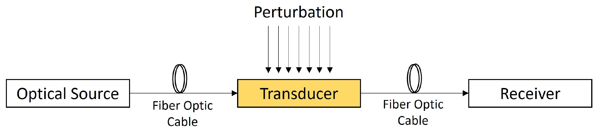
1.1. Fibre Optic Sensors

Fibre optic sensors may be defined as a means through which a measurand interacts with light guided in an optical fibre (an intrinsic sensor) or guided to and returned from an external medium (an extrinsic sensor) by an optical fibre to produce a corresponding optical signal [3]. Due to this interaction, changes in the measurand (perturbation of the system) produce resultant changes in specific properties of the optical signal. Figure 1 shows the typical block diagram of a fibre sensing system. In intrinsic sensors, the optical fibre is the transducer and directly modulates properties of light in response to the perturbation, whereas in extrinsic sensors an external medium is used for modulation [4]. Properties of the optical signal that can be modulated include amplitude, wavelength/colour, delay/phase and polarisation.
Since first patented in 1967, several technologies and applications of fibre optic sensors have been developed [5]. However, most of the advancements on fibre optics were focused on telecommunication and the sensors market was dominated by electronic sensors [3,6]. Recent developments in the last 20 years show that fibre optic sensors have significant potential in all industries, including the power industry. Some of its key features include [3,4,5,6,7]:
  • Physically small and light in weight;
  • Long lifetime;
  • General robustness;
  • Low attenuation;
  • Distributed or multiplexed measurements;
  • Electromagnetically passive and thus useful high-voltage systems.

1.2. Fibre Optic Sensor Technologies

1.2.1. Interferometric Sensors

Interferometric fibre optic sensors include a light splitter which splits the light into two arms: one isolated from the perturbation (reference arm) and one subjected to the perturbation (sensing arm). The light in the sensing arm experiences a change in delay and hence phase, relative to the reference arm as a result of the perturbation [6]. Interferometric sensors offer high sensitivity and correlating the phase change to the perturbation is relatively straightforward. Careful fabrication is required, however, to ensure the sensing arm is effectively biased [5].

1.2.2. Distributed Sensors

Distributed fibre optic sensors are based on detecting the back-scattering of light, typically using Raman or Brillouin principles [8]. In Raman scattering, the frequency of back-scattered light is shifted, and the intensity is temperature dependent. In Brillouin scattering, the frequency is also shifted but the magnitude of the shift is dependent on the temperature and strain of the fibre [9]. Measurements at several positions along the fibre are conducted by calculating the time between emitted light pulses and the back-scattered pulses, thus allowing distributed sensing. Distributed sensors offer high spatial resolution but have the drawback of long acquisition times [10].

1.2.3. Spectroscopy Sensors

Spectroscopy sensors are typically used for chemical sensing applications and use the medium under test as the transducer. Either broadband or narrow band light is emitted into the liquid or gas being tested and the absorption response can be used to determine the chemical composition of the medium [3]. These sensors have the benefit of simple optical source and collection geometries and can work as part of a point sensor network, but are limited to chemical sensing applications [5].

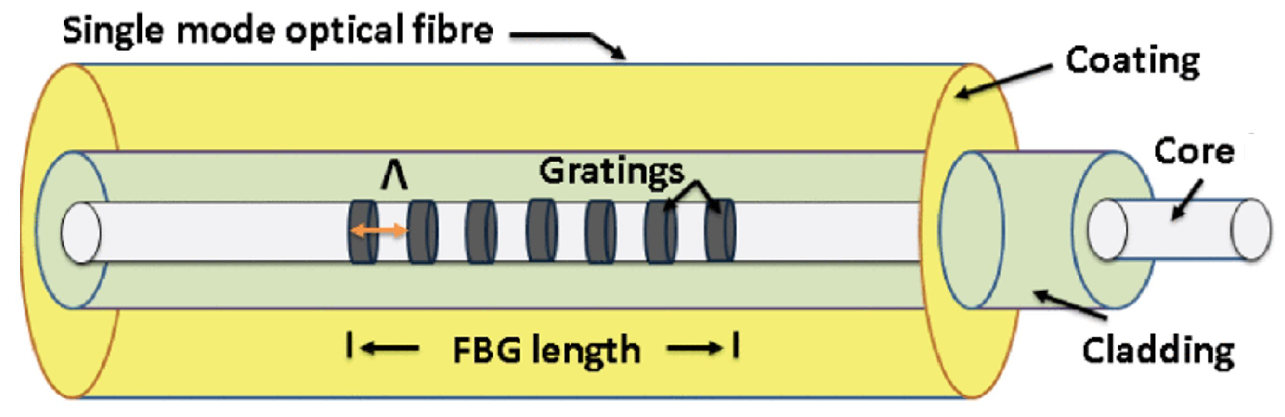
1.2.4. Fibre Bragg Grating (FBG) Sensors

FBG sensors consist of a single mode fibre with periodic changes in the refractive index of the core, termed ‘gratings’. The structure of the FBG sensor is shown in Figure 2. A sequence of adjacent equidistant gratings forms the sensing section of the fibre and is called a FBG sensing head. Due to the alternating layers of refractive indices in the core, light of a specific wavelength is reflected, which can be detected by an interrogator. The wavelength of the reflected light is modulated by temperature and strain of the fibre gratings, enabling direct measurement of these parameters. However, indirect sensing of other variables can be conducted by pairing with materials that function as strain transducers. Since the measurand data are encoded in the wavelength, FBG sensors are not affected by attenuation or power loss. They can also include an array of gratings on one fibre, allowing multi-point measurements.
Due to their multiplexing capability and range of sensing, FBG sensors have become an emerging technology for use in high-voltage applications. This paper will specifically review the advancements of FBG sensors for condition monitoring power transformers, transmission lines, overhead insulators, transmission towers and power cables. The aim of this work is to stimulate further development and deployment of FBG sensors in HV applications, as it will likely form part of the future grid asset management systems.

2. Overview of FBG Sensor Technology

The feature of multiplexing was made possible due to in-fibre gratings, which was first discovered by Hill in 1978 [11] by exposing the core of fibre to intense oppositely propagating argon laser beams. The result was periodic changes in the refractive index of the core, termed ‘gratings’. In 1989, Meltz [12] introduced a controllable method of fibre grating fabrication by exposing and illuminating the core from the side of the fibre with coherent UV radiation. This breakthrough spurred the research and commercialisation of FBG sensors [13].

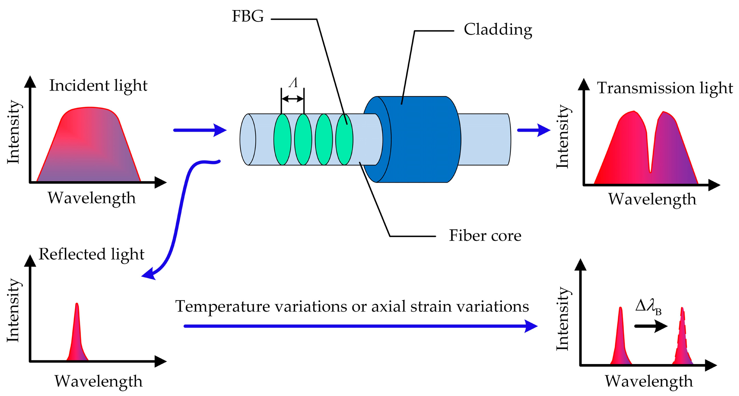
2.1. FBG Principle of Operation

When a fibre containing a FBG head is illuminated with broadband light, a particular wavelength is reflected, as illustrated in Figure 3. The wavelength of the reflected light is known as the Bragg wavelength and is as given by [14]:
λ B = 2 Λ n
where λ B is the Bragg wavelength, Λ is the grating period and n is the effective refractive index of the core.
The principle by which FBG sensors are used is based on detecting the shift in the wavelength of the reflected light and, therefore, its configuration only requires one end of the fibre to be connected to the interrogation setup [6]. The shift in the Bragg gratings wavelength occurs due to a change in the grating period or the effective refractive index and is dependent on the temperature and strain. When the fibre is stretched or compressed, the grating period is changed, resulting in a change in the Bragg wavelength, allowing the magnitude of strain to be computed. Temperature impacts the Bragg wavelength due to variation of the silica refraction index induced by the thermo-optic effect as well as the thermal expansion which alters the period of the microstructure [14]. Therefore, it can inherently act as a strain and/or temperature sensor, and packaged temperature and strain FBG sensors are readily available in the sensors market.
The Bragg wavelength shift due to applied strain ( Δ ϵ ) and temperature changes ( Δ T) is given by [14]:
Δ λ B λ B = k ϵ Δ ϵ + k T Δ T
The FBG sensitivity factors are design dependent and can vary with packaging and bonding methodologies [16]. For temperature and strain measurements in HV applications, specific packaging designs have been proposed, which are discussed in this paper. Measurement of other parameters requires specific materials to be incorporated which produce a strain effect that the FBG sensor can detect. Examples of designs to achieve sensing of various parameters in HV assets, including acoustic pressure, dissolved hydrogen and moisture are presented in the following sections.

2.2. FBG Multiplexing

One of the additional advantages of this FBG technology is its intrinsic multiplexing capability. Multiple gratings (each with a specific Bragg wavelength) can be coded on a single optical fibre and detected using single optical source. This structure is known as a FBG array sensor and is an attractive option for multi-point sensing [17,18]. In the sensor array, each FBG reflects a specific light spectrum matching its designed Bragg wavelength.

2.3. FBG Interrogation Techniques

There are several techniques for interrogating FBG sensors to determining the Bragg wavelength, such as the interferometric detection and the scanning Fabry Perot filter methods. In the interferometric method [19], the reflected light is passed to an unbalanced interferometer which has a transfer function dependent on the wavelength. This method can sample at high frequencies, but the range of Bragg wavelength shifts that can be detected is limited. The scanning Fabry Perot filter method can be used for FBG sensors that have Bragg wavelength shifts across the full spectrum [20]. Interrogators based on this technique [21] couple the FBG reflected light to a narrow band scanning filter. Since the filter sweeps over the expected wavelength range, at one point light will pass through and be detected at the output of the filter, which can be used to determine the Bragg condition.
To date, the principles surrounding FBG technology and its operation have been widely published in research journals. Thus, the remaining sections of this paper will focus on the application of FBG sensors in HV assets.

3. FBG Sensors for Condition Monitoring of Transformers

Power transformers are critical assets in power generation plants and transmission systems and, therefore, outages can incur high repair costs [22]. Transformer monitoring can aid in predicting major failures and allow repairs to be conducted at a reduced cost during a planned outage [23]. Monitoring is performed through an effective maintenance strategy which can include routine testing of the windings, insulation and oil composition, all of which are established in various standards [24,25]. These tests are critical during the transformer service life as various electrical and thermal stresses can result in degradation to the components of the transformer. For example, the insulating oil experiences ageing due to faults such as partial discharges and/or thermal faults [25]. Severe short circuit or lightning produces high radial and axial forces which can cause winding deformations [26]. Online monitoring technology has the advantages of reducing the interval between tests to nearly zero and allowing detection of changes shortly after the occurrence [27]. As a result, several parameters such as temperature, partial discharge, dissolved gas and winding deformation have been proposed for online monitoring using FBG technology.

3.1. Temperature

Hotspots and overheating in power transformers can lead to cracking of the windings and insulation ageing, reducing the service life [28]. Internal temperature monitoring can assist with failure prediction and thus power system reliability planning. Since the FBG sensor can directly measure temperature at multiple points, it is a viable option for use in transformer condition monitoring.
In [29], fibre consisting of 20 FBGs were taped to the outside of a 100 kVA transformer tank and loaded in a lab environment. The temperature measurements from the FBG matched with thermal camera imaging. This installation can be conducted quickly but does not provide an indication of the winding and insulation temperatures and is only suitable for dry type transformers, as shown in [30] where 10 FBG sensors were adhered to a 3 MVA mold transformer in the Korea grid. For oil immersed equipment, FBG sensors will have to be installed inside the transformer housing in the factory before being placed in service. To secure the fibre for these applications, insulating paper or protective packaging, as shown in Figure 4, is required. In [10], 12 protected FBG sensors were installed in a 20 MVA, 345/20 kV transformer at the lower and high-voltage bars and windings. Overloading tests were conducted in the laboratory to prove the viability of continuous hotspot monitoring using the FBG sensors.
To concentrate measurements on the coil, 24 sensor heads in fibre coated with high temperature polyimide and protected with insulating paper were installed on the outside of the windings during the manufacture of a 10 kV transformer [32]. Factory tests showed that the temperature rise measured from the FBG sensor was 83.7k vs. 48.9k measured from a probe at the top oil. Thus, measurement at just the top oil is not sufficient for thermal monitoring and ageing analysis. FBG sensors were also installed on the windings of a 5 kV [33] and 35 kV transformer [34]. The authors of [35] achieved fully online temperature monitoring by installing 3 arrays (11 gratings each) on the top of the 3 windings and various locations in the tank for oil measurement in a 110 kV transformer in Zhejiang Province, China. The authors of [31] also tested FBG temperature monitoring on a 110 kV transformer, but attached the sensors to both the core and windings. The authors of [36] aimed to increase the spatial distribution of the measurement for enhanced hotspot location and thermal ageing estimation. The actual winding temperature was recorded by using used slotted copper wire. The set-up consisted of 14 optical fibres and a total of 218 FBG sensors in the low-voltage (LV) and high-voltage (HV) coils, strips, iron core and top oil of a 35 kV/4000 kVA transformer. In order to obtain measurements closer to the iron core, [37] developed a spring-shaped carbon fibre clamp to fit around the core. When the transformer was subjected to nonlinear loads, the temperature recorded from the FBG sensor was within 1 when compared to readings from pyrometer (obtained directly on the core as the housing was removed for testing).
The existing research and development showed that during manufacture, FBG sensors can be embedded to enable online monitoring when placed in service. However, the warranty period of transformers usually lasts 30–35 years [38] and, therefore, the roll-out of this technology through overhaul will be a slow process. Alternatively, existing equipment can be retrofitted as performed in [39] during the factory repair period. During the repair, 14 sensors were installed in the windings, core, top oil level, bus bars of a 110 kV transformer and placed back in service. Results for 10 months were collected and used to estimate the thermal life loss.
Temperature monitoring using FBG sensor technology all reported high accuracy through the laboratory and field studies, proving that it is a viable option. An alternative fibre-based technology is distributed temperature sensors (DTS), which were also proposed in [40,41]. DTS offer higher spatial resolution tha FBG sensors, which are limited by measurements at fixed points. However, DTS have longer acquisition times and higher costs [10]. Among these two competing technologies, FBG sensors offer certain advantages and are useful for online monitoring depending on the application.

3.2. Partial Discharge

Partial discharge (PD) occurs in transformers due to defects in the insulation, and if not detected early, can lead to failure of the asset [42]. It refers to a localised electrical discharge which partially bridges the insulation between conductors [43]. Energy from the PD heats and evaporates some of the adjacent material creating high-frequency acoustic emissions up to several MHz [44] and, therefore, acoustic emission (AE) detection methods have been used for PD monitoring.
FBG sensors are sensitive to strain and can produce Bragg wavelength shifts due the mechanical pressures form the acoustic emissions. Due to their robustness and electromagnetic immunity, FBG sensors can be installed inside transformer tanks, improving the AE detection sensitivity versus other methods, and leading to earlier fault warnings [45]. The authors of [46] mounted a FBG sensor under pre-stress on a slotted acrylic sheet, so that it could be more sensitive to the acoustic waves. PD tests using a needle-plane electrode arrangement in an oil tank showed that the shift in peak Bragg wavelength was highly correlated (correlation coefficient of 0.85) with the PD amplitude measured using coupling capacitors.

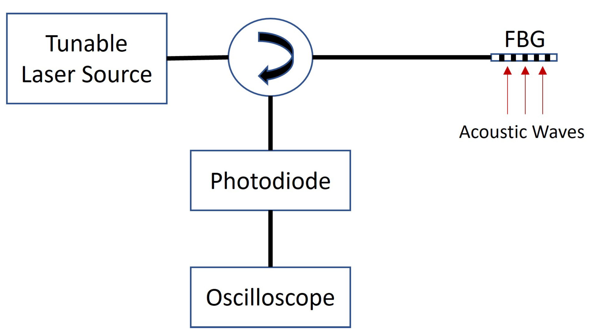
3.2.1. Tunable Laser-Based Interrogation for Improved Sensitivity

A challenge associated with using FBG sensors for measuring AE signals is the sensitivity of wavelength shifts at low PD amplitudes. Hence, the tunable laser-based interrogation developed in [47] is used for PD detection in favour of wavelength-based interrogation. In this method, a narrow-band laser source tuned at the mid-reflection wavelength of the FBG is illuminated in the fibre and the reflected light is measured by a photodiode, shown in Figure 5. Thus, shifts in the reflected spectrum are converted to a changing voltage signal which can be measured and analysed.
The authors of [48] energised a defect in an oil tank which produced a PD of 320–460 pC and compared the response of four FBG sensors placed inside the tank to a PZT acoustics sensor on the wall of the tank. The FBG detection method yielded higher sensitivity over a PZT-based acoustic transducer by 4.84 dB. The FBG sensor also has higher bandwidth response than the PZT transducer, as investigated in [49] using an acoustic actuator ranging from 20 to 500 kHz.

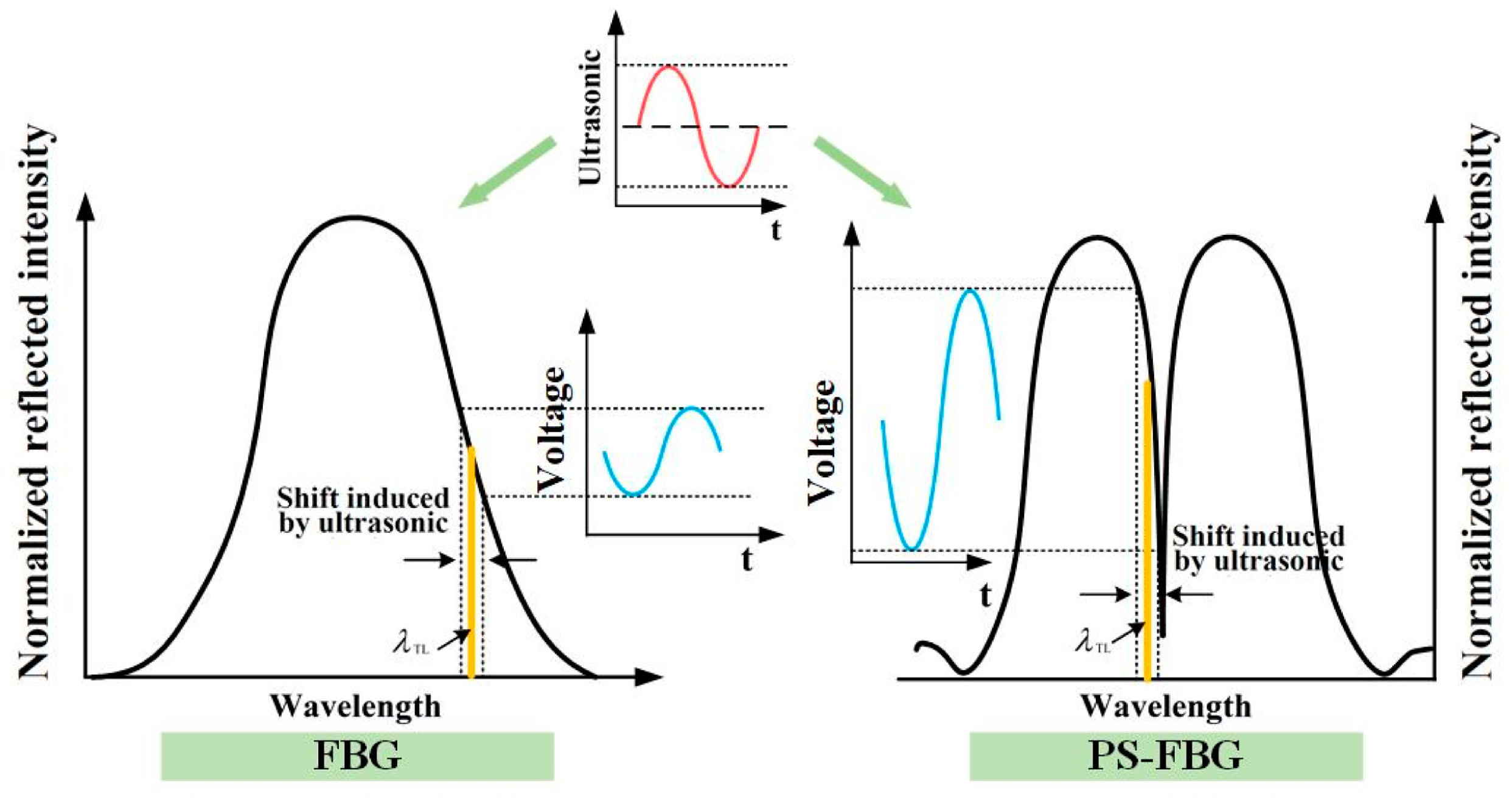
3.2.2. Phase-Shifted FBG Sensors for Improved Sensitivity

To further increase sensitivity, the authors of [48] repeated the experiments using phase-shifted FBG (PS-FBG) sensors. The π phase-shifted FBG has two peaks in the reflected spectrum and a narrow transmission window. This increases the slope of the linear region in the reflected spectrum, resulting in larger photo-intensity changes for the same shift in wavelength as compared to traditional FBG sensor, as shown in Figure 6. Simulations of reflected spectra showed that the introduction of a phase shift in a 1550 nm 10 nm length grating reduces the line width by approximately 16 times [50]. In PD tests, the PS-FBG sensor has a higher sensitivity of 17.5 times than PZT transducer, thus outperforming the traditional FBG sensor [45].

3.2.3. Acoustic Amplifiers for Improved Sensitivity

Passive acoustic amplifiers are also used to increase the sensitivity of FBG sensors to PD activity. In [51,52,53], a mandrel was used since it covers a broad frequency bandwidth, required for PD detection. In such an arrangement, the FBG sensor was attached to the outer wall of the mandrel to detect strains that the mandrel transfers to the fibre when an acoustic pressure wave strikes the cylinder. Elastic diaphragms were also proposed [54,55] since they vibrate with the acoustic signals, generating an amplified strain that the FBG head can measure. However, the sensitivity of this type of packaging is omnidirectional. In tests where the relative direction of the AE source was rotated, the response of the mandrel packaged sensor varied by less than 3% but the diaphragm-based sensor reduced by 80% when the AE source was normal to the diaphragm.

3.2.4. PD Location Detection

Since the FBG-based PD sensors relies on the acoustic emissions, the PD source location can be determined using the arrival times of the signals and the speed of sound in the medium, typically transformer oil [56]. This triangulation method described in IEEE standard C57.127 [57] was investigated in simulations [58,59] and tests [60,61], but was based on sensors mounted outside the tank. This is ineffective for real conditions due to blockage from the windings and the variation in sound velocities across different media (oil, steel walls) [57]. The FBG sensors can be installed inside the tank and hence mitigate these issues [62]. The authors of [63] mounted three FBG sensors in a 350 mm × 400 mm × 400 mm oil tank containing a metallic particle energized with a high-voltage test transformer. At 17 kV, a partial discharge of 600–700 pC occurred which was located within 25 mm using the arrival times at each FBG sensor. Signal processing techniques such as the Hilbert transform, discrete wavelength transform and cross recurrence plot analysis were applied in [64,65] to increase the SNR of the FBG responses and improve location estimation.

3.2.5. PD Classification

In addition to amplitude measurement and location detection, PD classification was performed using FBG sensors. The authors of [66] generated (1) corona, (2) surface and (3) particle movement discharges in various oils using (1) a needle-plane, (2) a pressboard sandwiched between an IEC-B electrode and ground plane and (3) sphere and particle electrodes, respectively. Ternary plots of the filtered acoustic emissions showed that the three types of discharges formed separate clusters suggesting possibilities of classification, regardless of oil type.

3.2.6. Outlook on PD Measurement using FBG Sensors

PD detection using FBG sensors are of high interest among research institutes, but current work is still limited to simulated discharges in test cells. Other fibre optic-based technologies for PD detection such as interferometric [67,68] and distributed sensors [69] have been proposed but are also in the preliminary stages. There currently exists a research gap between research facilities and field deployment of fibre optic-based PD measurements in transformers.

3.3. Oil Assessment

Overheating and internal faults accelerate the decomposition of transformer insulating oil and oil impregnated cellulose, leading to a loss of insulating properties and eventual failure [70]. This decomposition produces gaseous by-products including hydrogen (H2), methane (CH4), acetylene (C2H2), ethylene (C2H4), ethane (C2H6), carbon monoxide (CO) and carbon dioxide (CO2), which are monitored using dissolved gas analysis (DGA) [25]. Conventional DGA is conducted offline by lab testing samples of the transformer oil. Fibre optic sensors have the potential to perform online oil analysis since they can be installed inside the tank to record data throughout the transformer’s service life.

3.3.1. Hydrogen

Hydrogen is the principal gas produced during partial discharges and levels of >100 ppm should prompt additional investigation [25]. In several studies, FBG-based hydrogen sensors have been developed and tested with mineral oil. The typical structure of these sensors (Figure 7) involves a palladium (Pd) coating which has the ability to absorb hydrogen and expand, stretching the gratings, producing a Bragg wavelength shift [71]. The authors of [72] tested a FBG sensor glued to 100 μ m Pd foil in a chamber of mineral oil with varying amounts of hydrogen gas dissolved. The sensitivities in wavelength shift (pm) per hydrogen concentration (ppm) were 0.33 pm/ppm at 500 ppm and 0.18 pm/ppm at 2000 ppm, with a response time of 46 h. The authors proposed that slow response time is not detrimental to the application in a transformer, as gas generation rates are low and current sampling intervals are annually.
The sensor can be improved by first coating with polyimide (PI) and/or titanium (Ti) to use as adhesion layers to prevent the Pd from peeling off. The intermediate adhesion layer increases the robustness of the sensor but does not affect the sensitivity of the sensor, as tested in [73]. The authors of [74] coated a bare fibre with PI and then used magnetron sputtering to deposit uniform layers of Ti and Pd on the fibre. H2 concentrations ranging from 0 to 900 ppm in transformer oil were created by inserting a PD defect in a tank of transformer oil. A linear relationship between the Bragg wavelength shift (pm) and H2 concentration with a slope of 0.057 pm/ppm was observed.
As the H2 absorbed increases, the Pd structure changes from α phase to β phase and becomes susceptible to fractures [71]. Alloys were proposed as alternatives to provide higher structural stability. Tests were performed with pure Pd and Pd/Ag alloy sputtered on a FBG sensor [75]. Linear responses were also obtained with sensitivities of 0.044 pm/ppm and 0.055 pm/ppm for the pure Pd and alloyed Pd, respectively. Further advancement in the sensitivity of magnetron sputtered sensors was achieved by using side polished (SP-FBG), D-shaped fibres with the Pd coating only on the flat side of the fibre. The response of FBG and SP-FBG hydrogen sensors tested in [76,77] for concentrations of 0–700 ppm were 0.042 and 0.477 pm/ppm (>11 times sensitivity), since the curvature deformation caused by Pd on one side created a greater strain effect than axial expansion. The response time was 4 h, which was quicker than the 100 μ m foil used in [72].
The authors of [78] examined the reliability of the magnetron sputtered Pd/Ag alloy sensor by conducting 50 absorption and desorption cycles, with concentrations up to 2000 ppm. At the end of the experiment, the alloy film was still bonded but the adhesion weakened due to repeated expansions and contractions, leading to an 8% decrease in sensitivity. The sensor used did not include any PI or Ti adhesion layers and, therefore, more studies are required with different sensor designs. However, the initial reliability work along with the sensitivities for a wide range of hydrogen concentrations suggest that FBG sensors can be used in long-term online oil monitoring.

3.3.2. Moisture

Moisture is another key parameter for transformer monitoring as it affects the insulating properties of the oil [79]. In addition, when the cellulose paper absorbs moisture, its degradation and ageing rate increases [80]. Polyimide reacts with water and expands, similar to palladium film with hydrogen and, therefore, PI coated FBG sensors can be used for moisture detection. In [81], a PI coated FBG sensor was placed in a litre of dried mineral oil while demineralised water was pipetted and stirred in. The Bragg wavelength shift was linearly related to the water activity calculated using a moisture probe. The study was extended [82,83] by installing an array with PI-coated FBG sensors in 5 kVA transformers with mineral oil and FR3 oil. When subjected to 24 h cyclic loading, the water activity varied (due to cyclic absorption of moisture by the cellulose) which was detected by both the FBG array and a moisture probe. The authors of [84] exposed transformer oils to saturated humid air and obtained perfect correlation between wavelength shifts and water content for the ranges tested: 50–300 ppm in mineral oil and 5–30 ppm in ester oil. The high accuracy demonstrated in these studies suggests that PI-coated FBG sensors have the potential for development of online moisture monitoring in transformers.

3.3.3. General Ageing

The effective refractive index of fibre is a result of the core and the surrounding medium. Tests show that aged mineral transformer oil has a higher refractive index [85] and, therefore, this can be detected using fibre optic sensors. The authors of [86] obtained five field samples of differing oil quality for testing. Immersing the FBG head in the oil samples yielded different shifts in the Bragg wavelength. The study only contained preliminary results and, therefore, further tests are required to match the actual oil quality to the FBG measurements, to monitor overall ageing.

3.3.4. Outlook on Oil Assessment Using FBG Sensors

The existing research shows that FBG sensors can assist in DGA but is currently limited to water vapour and hydrogen. Other fibre optic technologies such as spectroscopy and luminescence reflection have been studied for oil ageing [87] and dissolved gas monitoring of acetylene [88] and methane [89], which are other key gases produced during internal transformer defects. More research and development is required to achieve full online DGA in transformers using FBG sensors.

3.4. Winding Deformation

Statistics show that over 20% of transformer failures are due to mechanical (bending, breaking, displacement, loosening) issues [90]. Lightning and short-circuits generate a large current and are likely causes since they lead to mechanical deformations in the windings [91].
The authors of [92] glued a FBG sensor transverse to the core laminations of a 3 kVA transformer to monitor these mechanical defects. Nonlinear loads applied to the transformer caused harmonic distortions and increased mechanical vibration of the windings which were detected by the FBG sensor. This lab-scaled study suggests that winding monitoring is possible, but the direct installation of fibre is not robust for long-term installations. The authors of [93] packaged three FBG sensors in polyether ether ketone (PEEK) and installed them on the upper-middle and lower part of a winding in a transformer. PEEK was used since it is rigid and has a low expansion coefficient. A Bragg wavelength shift of 0.133 pm/kPa was observed when the windings were subjected to strains from a pressure testing machine. Other sensor designs using FBG packaged in the transformerboard [94] and attached to the cantilever [95] were proposed but not yet tested.
The use of FBG sensors for structural monitoring of windings has potential but the research is still underdeveloped. In addition, other fibre optic technologies can work for this application such as distributed strain sensors using Brillouin scattering which have been proposed and lab tested using a power transformer [96,97].

4. FBG Sensors for Condition Monitoring of Transmission Line Conductors

Transmission line conductors on the HV network are mounted on towers with large spans and, therefore, are subjected to increasing ambient temperatures, wind and icing due to climate change effects along with the higher ampacities from growing energy demand. All of these factors can affect the reliable operation of transmission line infrastructure. For example, the fluctuations in the heat from power transfer or environmental conditions causes the conductor sag to vary which can limit the conductor clearances or ampacity [98]. Extreme icing on overhead transmission lines can lead to flash over, and mechanical impacts such as conductor breakage and tower collapse [99]. High wind speeds produce vibrations on the conductor which can create wear on the strands or tower fittings. Corrosion due to humidity and chemical pollutants is another phenomenon which impacts the reliability of overhead conductors [100]. Thus, multi-parameter condition monitoring of overhead transmission lines will be critical in future power grids. The roll-out of optical ground wire (OPGW) and the optical phase conductor (OPPC) represents a catalyst for integrating fibre-based sensors, especially in remote locations. Currently, several research tests and pilot projects have been conducted to monitor key conductor parameters such as temperature, sag, icing and vibrations using FBG sensors. Distributed sensing using Raman and/or Brillouin principles have also been tested for monitoring temperature and strain on transmission lines. This technology allows high spatial resolution and thus, measurements can be conducted along an entire line. However, FBG sensors have features such as faster acquisition times [10] and a wider range of measurement parameters, which may be more advantageous in certain overhead line applications.

4.1. Temperature

The FBG sensor response to temperature is established and, therefore, prototypes for use in transmission lines have been developed.
The authors of [101] built a temperature sensor by packaging a FBG sensor in two steel shells to protect from stress. The sensor was installed on an overhead line at the #44 tower of the 110 kV Zhengzou transmission line, China. A similar design instead with a 2 mm diameter copper tube was installed on a line inside the campus of the Universidad Nacional de Colombia with the aim of achieving a dynamic line rating [102]. These sensors were attached on the overhead conductor for heat transfer. Alternatively, an egg-shaped aluminium housing split in two halves that can be opened and clamped over the conductor was proposed in [103]. The housing included aluminium probes through which FBG sensors were inserted and secured with epoxy. After calibration, the sensor was installed on a 400 kV line in Subhasgram, Kolkata, shown in Figure 8.
Distributed temperature sensing of phase conductors using Raman and Brillouin scattering has also been proposed [104,105] using the fibre in OPGW/OPPCs which has the advantage of measuring temperature along an entire line. However, wide-scale deployment will be slow as grids are still transitioning from conventional conductors to OPPCs. The FBG temperature sensors are clamped on to existing transmission lines and can be deployed more quickly.

4.2. Sag

Sag can be calculated by applying the tension in the middle of the span to the catenary equation. Tension can be directly measured using a FBG strain sensor clamped directly onto the transmission line. As the conductor sags, the clamps move further apart, applying a strain to the gratings. FEA modelling of a clamping mechanism was conducted to ensure that the design transferred the strain to the FBG sensors [106]. Simpler versions of the clamps were lab tested [107] and installed on a 110 kV line [108], shown in Figure 9.

4.3. Icing

The concept of using FBG sensors for ice monitoring was presented [109] in 1997 by attaching a strain beam with fibre bonded between the overhead conductor and insulator to determine additional tension on the lines due to the icing. Designs have improved since and avoid the transmission line by connecting the tension sensor between the tower cross arm and low voltage side of the insulator (Figure 10). Tests were carried out to validate the linearity of the FBG sensor response by applying a tensile load across the connecting points of the strain beam [110]. In this design, a separate temperature compensation FBG was required to detect only the strain. A similar FBG tension sensor was attached to an insulator, lab tested in an ice chamber and then installed on an 800 kV HVDC line Yun Guang in [105]. Weights were hung from the transmission lines to simulate the load of icicles. The Bragg wavelength increased with the weight but also with environmental temperature. A separate Brillouin optical scheme was carried out in the OPGW for temperature compensation. However, the conductor has a higher temperature than the ground wire and, therefore, this scheme should be used for OPPCs.
These strain beams are influenced by both axial and eccentric load. The authors of [111,112] proposed an I beam structure instead of a column-type beam since it has a higher accuracy under eccentric axial load. The I beam was made using an elastic element and included diagonal grooves in either end for fitting the FBG heads. Through FEA modelling, the design was built so that with applied load, one end is compressed and another one is stretched, allowing compensation of temperature. Loading using weights in an outdoor environment and in an icing chamber were conducted to ensure reliability of the sensor in all conditions. The structure was further modified [113] to include a cantilever to allow tilt measurements. This prototype was tested under various mechanical loads in the lab and a 250 h outdoor experiment which included a snowstorm, proving the robustness of the design. A combined strain and tilt sensor assembly, using the cantilever design, was installed on the #44 tower of the 110 kV Zhengzou line, China [114], to accompany the temperature sensor discussed in [101]. The authors of [115] used a standard FBG strain sensor on a tower with a 1 m length OPGW attached as a sample line for testing. The results showed that the wind affected the response and subsequently a correction factor for effective gravity acceleration and moving average filter were added to the measurements to improve accuracy.
Figure 10. Schematic of transmission line monitoring with FBG tension sensor [116].
Energies 16 06709 g010
Similar to distributed temperature sensing, Brillouin scattering can be used to measure strain on the line due to icicle loads. However, this technology is limited to the availability of the OPPC infrastructure. The FBG tension sensor has the advantage of measuring other parameters including mechanical vibrations, as discussed in the following sections.

4.4. Mechanical Vibrations

In addition to static mechanical loads (e.g., icing), transmission lines are affected by dynamic strains which include aeolian vibrations and galloping.

4.4.1. Aeolian Vibrations

Aeolian Vibrations, caused by low to moderate winds, are vertical oscillations with amplitudes small in comparison to the line diameter. The effects are long-term wear to the suspension clamps and broken conductor strands [117,118]. To measure aeolian vibrations, two FBG sensors were bonded directly onto a 60 kV transmission line in Trondheim, Norway [117]. Vibrations from 0.065 Hz to 12 Hz occurred on the transmission line with amplitudes varying according to the wind speeds. This case study conducted in 2000, proved that FBG sensors can be used for dynamic mechanical loading of transmission conductors, but more robust sensor packaging would be required. The authors of [119] designed a cantilever beam structure that clamps over the conductor. Through FEA simulations, the optimal placement of the FBG sensor to transfer strain was determined. This sensor was built and withstood tests [118] on a 10 m sample conductor attached to a vibration test bench, validating its use for online aeolian vibration monitoring.

4.4.2. Galloping

Galloping is a low frequency, high amplitude vibration caused by medium to strong winds. It can lead to loosening of cross arm bolts, damaged insulator strings and flash over as phases can breach clearances [120]. The authors of [121] clamped a standard FBG strain sensor to a 70 m sample conductor attached to a galloping tester located in the State Grid Key Laboratory of Power Overhead Transmission Line Galloping (Zhengzhou, China). Since the frequency of oscillations is low, static FBG load sensors can be used for such measurements, standardising installations and reducing the fibre/packaging required for multi-parameter monitoring of transmission lines. The tension sensor presented in [111,112] for icing measurement was tested for monitoring of galloping [116] by applying dynamic loads of 0.2 Hz to 3 Hz, using the force amplitudes from 2 kN to 10 kN. It exhibited stable response over the frequency range. The FBG sensor also yielded high accuracy when connected to the galloping line tester. These sensors, however, measure the magnitude of the dynamic strain but do not distinguish galloping in the horizontal and vertical directions. As a result, [122] placed three FBG sensors, spaced 120 apart in a ball eye fitting, in order to decouple the tension into both horizontal and vertical components. The design was field tested on a transmission line in Henan, China, and the accuracy was validated using a video monitoring system set up at the same tower.

4.5. Fault Detection for Power System Protection

In addition to the physical monitoring of conductors, FBG-based sensors have been proposed for building current sensors to be used in fault detection. Opto-magnetic current sensors were developed in [123] by attaching fibre gratings to magnetostrictive materials such as Terfenol-D, which produces a strain due to the AC magnetic field around the current flowing in a conductor. Simulations on radial and network power systems with opto-magnetic current sensors placed 3 cm away from each phase conductor showed that fault currents can be detected and used for relay operation [124]. An alternative FBG-based current measurement device was built using a piezoelectric stack connected to a Rogowski coil [125]. The output voltage of the coil will cause a strain deformation in the stack due to the inverse piezoelectric effect, which the FBG sensor can detect. The sensor was integrated with protection relays in [126]. These FBG-based current sensors offer fast response to transients and easy installations due to their small sizes and, therefore, are a promising alternative to traditional current transformers. Optical current transformers without Bragg gratings also exist since first proposed for HV transmission lines in the 1960s [127]. These current sensors were based on the Faraday effect and the various interrogation techniques to measure the Faraday rotation are presented in [128]. However, the FBG-based sensor has the advantage of interfacing with a standard interrogator that monitors the fault current along with the physical parameters [126] discussed on the previous sections.

5. FBG Sensors for Condition Monitoring of Composite Insulators

Overhead insulators are key components in transmission line infrastructure as they support the conductors and also provide insulation between the high voltage phase and the grounded tower cross arms. Porcelain, glass and composite insulators are mainly used in transmission lines, with the latter having advantages of lighter and smaller structures, and higher hydrophobicities [129]. While composite insulators should be designed to withstand pollution and icing [130], in extreme conditions these climate impacts can cause tracking and puncturing of the insulation surface [131]. Conducive bird droppings and biological contamination, such as algae, can also affect the insulator performance and lead to flash over [131]. These assets are also prone to mechanical defects such as cracking of the core rod due to mechanical load and chemical erosion [132]. Some of the existing live line inspection techniques include visual inspections, IR thermography, acoustic emission and electric field measurement [133], and the pros and cons of each method were reviewed by a CIGRE working group in [134]. Due to the construction of the composite insulators, research showed the possibility of embedding fibre optic cables within the housing. This encouraged work into monitoring of key parameters of the insulator using FBG sensors to aid in condition monitoring and diagnostics.

5.1. Structural Faults

Failure mode analysis of composite insulators shows that decay-like and brittle fractures are common defects which occur under environmental and mechanical stresses [135]. FBG sensors can directly measure strain and tests prove that structural monitoring of insulator core rods can be achieved. The authors of [136,137] bonded FBG heads to the surface of core rod subjected to pulling forces, ranging 0–50 kN, which created linear changes in Bragg wavelength. For a more robust design, the fibre can be embedded in the core rod during manufacturing. The authors of [138] built a core rod with nine FBG heads through the centre and showed the sensors matched the changes in tensile stress. This design was also applied to a 220 kV insulator using three gratings [139,140]. After strain calibration tests in the lab, the insulator was placed in service and successfully detected stresses caused by a strong gale during 7–9 August 2012.
The FBG sensors can also assist with detecting crack initiation and the development of cracks to fractures, as proposed in [141]. A 10 kV composite insulator rod with four fibres, each with five gratings pasted on the surface, was tested under mechanical load until cracks and eventual fractures formed. The Bragg wavelengths either increased or decreased (depending on the relative sensor location) with crack development, and, therefore, can be used for early warning of cracks in the core rod.

5.2. Temperature

Internal defects cause internal discharge and increase the surface current leading to temperature rises [142]. Detecting abnormal heating can therefore assist with failure prediction. Along with mechanical strain, embedded FBG sensors in the core rod can directly monitor temperature. This arrangement has been developed and tested in the lab [143] and in the field on 110 kV [101] and 220 kV insulators [139,140].
Temperature monitoring through embedded FBG sensors can also allow early detection of arcing events. This is critical in polluted environments where insulators are susceptible to the high leakage current and discharge activities over their surfaces [144]. Results from dry band arc studies [145,146,147] on insulators with FBG temperature sensors showed a drop in the temperature of the moist polluted composite insulator due to evaporation, followed by rapid increase in temperature during the arc. The arc discharge can therefore be found earlier by using the time point when the temperature begins to drop sharply.

5.3. Icing

In cold and high humidity environments, insulators can be covered by ice, leading to possible flash overs. The strain created by the weight of ice formation can be measured using the FBG sensors bonded onto the core rod. Ice loading was simulated in [148,149] by hanging weights on the sheds of a composite insulator with three FBG sensor arrays embedded. Figure 11 shows the schematic of the FBG array embedded between the core rod and the housing of the insulator. The wavelength shifts were linearly related to the simulated load, but the coefficient was dependent on the location of the icicle relative to the FBG in the core rod. Additionally, for multiple icicle loads, the wavelength shifts can be either additive or subtractive and thus a location algorithm is required. The research was extended [150,151] to develop the location detection system using 6 fibres each with 13 distributed FBG sensors. Tests in an artificial icing climate chamber prove that the shed number and axial position (within 60 degrees) of the icicles can be determined. This arrangement is costly due to the number of sensors required and further work can be carried out to optimise the design.

5.4. Salt Contamination

Contamination adversely affects the dielectric performance and reliability of HV insulators. In high salt fog conditions, the dielectric strength can be reduced by up to 80% [152]. Online monitoring of salt deposits is another method to improve condition monitoring of insulators. As previously discussed, polyimide-coated FBGs are sensitive to humidity since they absorb water, creating axial expansion of the grating. However, in the presence of salt fog, the salt re-absorbs the water from the PI layers, leading to a reduced wavelength shift of the FBG sensor. Lab tests of a FBG sensor mounted on a ceramic disc in a humidity chamber (95% relative humidity) with repeated salt fog sprays show that the Bragg wavelength is affected by the equivalent salt deposit density [153,154]. The effect of salt deposits is not the same at different humidities and more work is required to determine the response of PI-coated FBG sensors in actual environmental conditions.

6. FBG Sensors for Condition Monitoring of Transmission Towers

The transmission tower represents the support structure for transmission lines and should withstand additional loads such as wind and icing [130]. However, extreme winds and manufacturing defects can lead to structural damage to the tower [155,156]. Thus, condition monitoring of transmission towers is critical as a single failure usually triggers a cascading failure involving a number of adjacent towers along the line, incurring significant costs and outages [157].
Standard packaged FBG strain sensors enable structural monitoring and have been applied to several transmission towers. The installation process first involves FEA simulations of the tower to determine the weak points at which strain monitoring are most critically required. The authors of [158] installed FBG strain sensors on the angle braces of a transmission tower at Mount Jianshan, China. FEA simulations and lab tests were conducted to determine the position of maximum strain transfer from the angle brace to the sensor, prior to welding installation. Live monitoring showed increased strains on the tower due to wind-induced galloping (recorded using a camera). The authors of [159] opted for an ‘L’-shaped clamp installation using anti-loosening bolts. A total of 16 FBG strain sensors were installed on the weak points of a 500 kV transmission line tower in Hubei Province, China. The authors of [160] developed an elastic matrix rated at 360 MPa (higher than the maximum allowable stress of steel used in towers) to transfer strain to the fibre grating. The packaged sensor was installed on the key sections of the #44 tower of a 110 kV transmission line tower, Jibei, China, and sealed with 3 M waterproof cement. High stress recorded by one sensor in August 2015 revealed settlement displacement of one foot by approximately 5 mm, which prompted preventative measures.
Tower vibration can also be used in condition monitoring since changes in the vibration frequency of the tower will indicate mechanical deformation of the structure. The authors of [161] installed a FBG vibration sensor on a 220 kV transmission tower in the south coast of China, which is subject to strong winds and hurricanes every year.
Soil displacement and landslides are also major causes of tower defects in areas with high land movement [162]. FBG-based soil displacement sensors were installed at the #50 tower in Sichuan, China, which is affected by earthquakes [163]. Similar FBG sensors were used at a transmission tower in the Maoxian, Sichuan Province, China, to measure surface and deep soil displacements [164]. The monitoring results indicated a shallow and slowly moving landslide which caused the tower to be deformed, allowing relocation before total collapse.
FBG sensors can also be used for monitoring of critical bolts in the transmission tower. Shear stresses on the bolt and loosening of the nut due to galloping have been proposed and lab tested in [165,166]. These ’smart’ bolts are made by inserting one or multiple FBG sensors in the shank.

7. FBG Sensors for Condition Monitoring of Power Cables

High voltage power cables are used for connections in urban and submarine areas. The cable construction includes a conducting core, polymeric insulation and an outer sheath for mechanical and environmental protection [167]. Similar to overhead infrastructure, power cables will be under the influence of electric, thermal, mechanical and environmental factors which lead to degradation and ageing. Several failure causes exist for power cables and were listed by a CIGRE working group in [168]. Some of these include electrical treeing, overheating, improper handling and installation, fatigue of the outer sheath, moisture and ground chemical contamination. Cables are also vulnerable to external damage from excavation works since they are typically installed underground [169]. When a fault occurs on a power cable, digging to determine the location incurs repair delays. Among available online diagnostics tests of power cables, visual inspection, partial discharge and temperature measurements are the most commonly practiced by utilities [168]. FBG sensors may offer a new technology to conduct these online diagnostics, and thus initial research has been explored in this area.
Packaged FBG temperature sensors were developed in [170,171] for use of monitoring power cables in harsh, moist underground conditions. A metal armoured FBG temperature sensor was developed to resist strains and bites of rodents for application in underground pits. A total of 60 of these metal armoured sensors were installed in four cable pits in the substation in the Yunnan power network, Yanjin, China [172].
The cable joint is the weakest point in the cable and is the location where most failures occur. Therefore, monitoring of potential defects at these locations is critical for asset management [173]. The authors of [174] placed a FBG sensor inside a metal spring hosing and installed it on a cable joint in an underground cable, Korea. Field test results showed that the temperature measurement was proportional to the power through the cable.
Distributed temperature sensing of cables using Raman or Brillouin scattering is more actively researched [175,176] since cables with fibres embedded can be manufactured. However, in existing cable installations, FBG technology can be easier deployed, as shown in Figure 12, by clamping on the cable surface. Protective heat transduction packaging is only required at the sensor head(s) and the rest of the fibre can be sealed using other cheaper means. For newer cable installations that can include embedded fibres, FBG sensing does not offer a more attractive technology to distributed sensing, unless other condition monitoring parameters can be integrated.
Partial discharge monitoring was attempted in [177] using a needle inserted in a 1.5 m XLPE cable to form a spine defect. The voltage of the needle was increased until an obvious FBG response was observed, which occurred at a discharge of 7124 pC. While this shows it is possible to detect PD in cables, the current state of the technology is impractical as it is only sensitive to high levels of discharge and, therefore, cannot provide early warning of defects. The authors of [178] investigated whether PD can lead to detectable temperature changes in the cable, allowing indirect PD measurement. A cable joint with a knife scratch defect was placed in a constant temperature chamber and results showed a temperature variation of 0.2 caused by a partial discharge of 300 pC. However, this temperature difference is low and difficult to distinguish when placed in actual operating conditions.

8. Conclusions

FBG sensors are a promising technology for condition monitoring of HV assets. Various key parameters in transformers, transmission lines, overhead insulators, transmission towers and power cables have been researched, and in certain cases, deployed in HV equipment. Other fibre-based technologies, such as distributed sensing for temperature and strain of overhead lines and spectroscopy for transformer oil analysis, have also been tested. However, these competing technologies are not as versatile as FBG sensors. Thus, FBG sensors can enable multi-parameter condition monitoring of assets.
This unique ability has attracted attention in field applications such as the #44 tower of the 110 kV line in Zhengzou, China, where several FBG sensors including angle, tension, temperature and aeolian vibration sensors were installed for condition monitoring [114]. The FBG technology allowed all of these parameters to be monitored, with the principles of operation discussed in the earlier chapters.
The authors in this work have reviewed the current technology readiness levels (TRLs) of FBG sensors for various condition monitoring parameters in transformers, overhead infrastructure and cables with the aim of stimulating further research, development and deployment in this area. A summary of TRLs for these parameters in shown in Figure 13.
At this stage, FBG sensors are feasible for deployment in the field to monitor certain parameters of each HV asset. For example, FBG sensors for temperature measurement are established and, therefore, have been installed in the field in transformers, cables, transmission lines and overhead insulators. Similarly, structural monitoring using FBG technology has been demonstrated in the field for overhead infrastructure. Two cases have been presented where the online structural monitoring of transmission towers prompted preventative maintenance actions before tower collapse.
While the TRL levels of these parameters have reached the deployment stage, the installation cases are still relatively new (within the last decade) and exist in a few locations. Wide-scale roll-out and long-term reliability have not been proven as FBG sensors can be susceptible to ageing and failure due to installation and harsh environmental conditions. To provide warning of this issue, Ref. [179] developed a fault detection for FBG sensing systems. Another consideration for wide-scale deployment is the management of data. Multi-parameter online condition monitoring systems will generate large amounts of data which can assist in big data and digitalisation of assets [180] but will increase storage requirements. The incorporation of FBG sensors along with interrogation and storage will therefore increase the costs of the power system and substation equipment. Investment in condition monitoring systems for larger assets such as power transformers and transmission towers may be feasible but smaller assets such as composite insulators may not be justified at this time. Increasing the capacity of commercially available interrogators would also assist in increasing the practical adoption potential of FBG sensing in this context. With more cases of deployment and commercial availability, FBG-based systems can be more cost competitive, encouraging adoption by grid operators.
Other condition monitoring parameters such as partial discharge in cables and transformers are currently more challenging to deploy but continue to be of interest among research facilities. Dissolved gas analysis in transformer oil is another condition monitoring technique that has the potential for field application based on the initial test results published in the literature. With further advancements in the future, these parameters in the research and development stages can be rolled out in assets. This will allow a comprehensive sensing system to be built using one type of fibre optic technology which can reduce the overall cost of the condition monitoring equipment and spur interest among grid operators to adopt the technology into their HV assets.

Author Contributions

Conceptualization, V.P. and S.D.; methodology, V.R.; investigation, V.R.; writing—original draft preparation, V.R.; writing—review and editing, V.P. and S.D. All authors have read and agreed to the published version of the manuscript.

Funding

This research received no external funding.

Institutional Review Board Statement

Not applicable.

Informed Consent Statement

Not applicable.

Data Availability Statement

Not applicable.

Conflicts of Interest

The authors declare no conflict of interest.

Abbreviations

The following abbreviations are used in this manuscript:
HVHigh voltage
LEDLight emitting diode
HVDCHigh-voltage direct current
EMIElectromagnetic interference
FBGFibre Bragg grating
DTSDistributed temperature sensor
PDPartial discharge
AEAcoustic emission
PS-FBGPhase-shifted fibre Bragg grating
PZTLead zirconate titanate
PEEKPolyether ether ketone
DGADissolved gas analysis
PIPolyimide
SP-FBGSide-polished fibre Bragg grating
OPGWOptical ground wire
OPPCOptical power conductor
FEAFinite element analysis
XLPECross-linked polyethylene
TRLTechnology readiness level

References

  1. Montanari, G.C.; Fabiani, D.; Morshuis, P.; Dissado, L. Why residual life estimation and maintenance strategies for electrical insulation systems have to rely upon condition monitoring. IEEE Trans. Dielectr. Electr. Insul. 2016, 23, 1375–1385. [Google Scholar] [CrossRef]
  2. Burillo, D. Chapter 5—Effects of climate change in electric power infrastructures. In Power System Stability; Okedu, K.E., Ed.; IntechOpen: Rijeka, Croatia, 2018. [Google Scholar] [CrossRef]
  3. Culshaw, B. Optical fiber sensor technologies: Opportunities and-perhaps-pitfalls. J. Light. Technol. 2004, 22, 39–50. [Google Scholar] [CrossRef]
  4. Castrellon-Uribe, J. Chapter 1—Optical fiber sensors: An overview. In Fiber Optic Sensors; Yasin, M., Harun, S.W., Arof, H., Eds.; IntechOpen: Rijeka, Croatia, 2012. [Google Scholar] [CrossRef]
  5. Culshaw, B.; Kersey, A. Fiber-Optic Sensing: A Historical Perspective. J. Light. Technol. 2008, 26, 1064–1078. [Google Scholar] [CrossRef]
  6. Elsherif, M.; Salih, A.E.; Muñoz, M.G.; Alam, F.; AlQattan, B.; Antonysamy, D.S.; Zaki, M.F.; Yetisen, A.K.; Park, S.; Wilkinson, T.D.; et al. Optical Fiber Sensors: Working Principle, Applications, and Limitations. Adv. Photonics Res. 2022, 3, 2100371. [Google Scholar] [CrossRef]
  7. Mohammed, A.; Hu, B.; Hu, Z.; Djurović, S.; Ran, L.; Barnes, M.; Mawby, P.A. Distributed Thermal Monitoring of Wind Turbine Power Electronic Modules Using FBG Sensing Technology. IEEE Sens. J. 2020, 20, 9886–9894. [Google Scholar] [CrossRef]
  8. Ukil, A.; Braendle, H.; Krippner, P. Distributed Temperature Sensing: Review of Technology and Applications. IEEE Sens. J. 2012, 12, 885–892. [Google Scholar] [CrossRef]
  9. Amira, Z.; Mohamed, B.; Tahar, E. Monitoring of temperature in distributed optical sensor: Raman and Brillouin spectrum. Optik 2016, 127, 4162–4166. [Google Scholar] [CrossRef]
  10. Lobo Ribeiro, A.B.; Eira, N.F.; Sousa, J.M.; Guerreiro, P.T.; Salcedo, J.R. Multipoint Fiber-Optic Hot-Spot Sensing Network Integrated Into High Power Transformer for Continuous Monitoring. IEEE Sens. J. 2008, 8, 1264–1267. [Google Scholar] [CrossRef]
  11. Hill, K.O.; Fujii, Y.; Johnson, D.C.; Kawasaki, B.S. Photosensitivity in optical fiber waveguides: Application to reflection filter fabrication. Appl. Phys. Lett. 1978, 32, 647–649. [Google Scholar] [CrossRef]
  12. Meltz, G.; Morey, W.W.; Glenn, W.H. Formation of Bragg gratings in optical fibers by a transverse holographic method. Opt. Lett. 1989, 14 15, 823–825. [Google Scholar] [CrossRef]
  13. Hill, K. Photosensitivity in optical fiber waveguides: From discovery to commercialization. IEEE J. Sel. Top. Quantum Electron. 2000, 6, 1186–1189. [Google Scholar] [CrossRef]
  14. Jin, W.; Lee, T.; Ho, S.; Ho, H.; Lau, K.; Zhou, L.; Zhou, Y. Structural Strain and Temperature Measurements Using Fiber Bragg Grating Sensors. In Guided Wave Optical Components and Devices; Elsevier Inc.: Berkeley, CA, USA, 2006; pp. 389–400. [Google Scholar] [CrossRef]
  15. Wei, J.; Hao, Y.; Fu, Y.; Yang, L.; Gan, J.; Yang, Z. Detection of Glaze Icing Load and Temperature of Composite Insulators Using Fiber Bragg Grating. Sensors 2019, 19, 1321. [Google Scholar] [CrossRef] [PubMed]
  16. Mohammed, A.; Djurovic, S. In-Situ Thermal and Mechanical Fibre Optic Sensing for In-Service Electric Machinery Bearing Condition Monitoring. In Proceedings of the 2019 IEEE International Electric Machines I & Drives Conference (IEMDC), San Diego, CA, USA, 12–15 May 2019; pp. 37–43. [Google Scholar] [CrossRef]
  17. Mohammed, A.; Djurović, S. FBG array sensor use for distributed internal thermal monitoring in low voltage random wound coils. In Proceedings of the 2017 6th Mediterranean Conference on Embedded Computing (MECO), Bar, Montenegro, 11–15 June 2017; pp. 1–4. [Google Scholar] [CrossRef]
  18. Mohammed, A.; Djurović, S. FBG Thermal Sensing Ring Scheme for Stator Winding Condition Monitoring in PMSMs. IEEE Trans. Transp. Electrif. 2019, 5, 1370–1382. [Google Scholar] [CrossRef]
  19. Kersey, A.D.; Berkoff, T.A.; Morey, W.W. High-resolution fibre-grating based strain sensor with interferometric wavelength-shift detection. Electron. Lett. 1992, 28, 236–238. [Google Scholar] [CrossRef]
  20. Wang, G.; Pran, K.; Sagvolden, G.; Havsgård, G.B.; Jensen, A.; Johnson, G. Ship hull structure monitoring using fibre optic sensors. Smart Mater. Struct. 2001, 10, 472. [Google Scholar] [CrossRef]
  21. Jackson, D.; Lobo Ribeiro, A.; Reekie, L.; Archambault, J. Simple multiplexing scheme for a fiber-optic grating sensor network. Opt. Lett. 1993, 18, 1192. [Google Scholar] [CrossRef]
  22. N’cho, J.S.; Fofana, I.; Hadjadj, Y.; Beroual, A. Review of Physicochemical-Based Diagnostic Techniques for Assessing Insulation Condition in Aged Transformers. Energies 2016, 9, 367. [Google Scholar] [CrossRef]
  23. CIGRE. Guide on Economics of Transformer Management; Technical Report; CIGRE: Paris, France, 2004. [Google Scholar]
  24. C57.12.90-2015; IEEE Standard Test Code for Liquid-Immersed Distribution, Power, and Regulating Transformers. IEEE: Piscataway, NJ, USA, 2016; pp. 1–120. [CrossRef]
  25. C57.104-2019; IEEE Guide for the Interpretation of Gases Generated in Mineral Oil-Immersed Transformers. IEEE: Piscataway, NJ, USA, 2019; pp. 1–98. [CrossRef]
  26. Ebrahimi, B.M.; Fereidunian, A.; Saffari, S.; Faiz, J. Analytical estimation of short circuit axial and radial forces on power transformers windings. IET Gener. Transm. Distrib. 2014, 8, 250–260. [Google Scholar] [CrossRef]
  27. CIGRE. Guide for Transformer Maintenance; Technical Report; CIGRE: Paris, France, 2011. [Google Scholar]
  28. Duan, R. Real-Time Hotspot Tracing and Model Analysis of a Distributed Optical Fiber Sensor Integrated Power Transformer. IEEE Access 2022, 10, 57242–57254. [Google Scholar] [CrossRef]
  29. Badar, M.; Lu, P.; Wang, Q.; Boyer, T.; Chen, K.P.; Ohodnicki, P.R. Real-Time Optical Fiber-Based Distributed Temperature Monitoring of Insulation Oil-Immersed Commercial Distribution Power Transformer. IEEE Sens. J. 2021, 21, 3013–3019. [Google Scholar] [CrossRef]
  30. Kim, M.; Lee, J.H.; Koo, J.Y.; Song, M. A study on internal temperature monitoring system for power transformer using pptical fiber Bragg grating sensors. In Proceedings of the 2008 International Symposium on Electrical Insulating Materials (ISEIM 2008), Yokkaichi, Japan, 7–11 September 2008; pp. 163–166. [Google Scholar] [CrossRef]
  31. Gong, R.; Ruan, J.; Chen, J.; Quan, Y.; Wang, J.; Duan, C. Analysis and Experiment of Hot-Spot Temperature Rise of 110 kV Three-Phase Three-Limb Transformer. Energies 2017, 10, 1079. [Google Scholar] [CrossRef]
  32. Wang, L.; Wang, Q.; Qin, W.; Liao, T.; Yang, H.; Ma, G. Temperature Monitoring of Distribution Transformer Windings Based on Fiber Bragg Grating Array. In Proceedings of the 2019 2nd International Conference on Electrical Materials and Power Equipment (ICEMPE), Guangzhou, China, 7–10 April 2019; pp. 601–604. [Google Scholar] [CrossRef]
  33. Chen, W.-G.; Liu, J.; Wang, Y.-Y.; Liang, L.-M.; Zhao, J.-B.; Yue, Y.-F. The Measuring Method for Internal Temperature of Power Transformer Based on FBG Sensors. In Proceedings of the 2008 International Conference on High Voltage Engineering and Application, Chongqing, China, 9–12 November 2008; pp. 672–676. [Google Scholar] [CrossRef]
  34. Jiang, Y.; Liu, S.; Xiao, L.; Li, W. Fiber Bragg grating sensors for temperature monitoring in oil-immersed transformers. In Proceedings of the 2016 15th International Conference on Optical Communications and Networks (ICOCN), Hangzhou, China, 24–27 September 2016; pp. 1–3. [Google Scholar] [CrossRef]
  35. Wang, C.; Ding, N.; Zhan, J.; Mu, H.; Zhang, G.; Qian, P. Research on application of distributed FBG in on-line temperature sensing of power transformer. In Proceedings of the 22nd International Symposium on High Voltage Engineering (ISH 2021), Xi’an, China, 21–25 November 2021; Volume 2021, pp. 2034–2039. [Google Scholar] [CrossRef]
  36. Deng, J.G.; Nie, D.X.; Pi, B.X.; Xia, L.; Wei, L. Hot-spot temperature and temperature decay rate measurement in the oil immersed power transformer through FBG based quasi-distributed sensing system. Microw. Opt. Technol. Lett. 2017, 59, 472–475. [Google Scholar] [CrossRef]
  37. Kuhn, G.G.; Sousa, K.M.; Martelli, C.; Bavastri, C.A.; Silva, J.C.C.D. Embedded FBG Sensors in Carbon Fiber for Vibration and Temperature Measurement in Power Transformer Iron Core. IEEE Sens. J. 2020, 20, 13403–13410. [Google Scholar] [CrossRef]
  38. Ma, G.; Wang, Y.; Qin, W.; Zhou, H.; Yan, C.; Jiang, J.; Ju, Y. Optical sensors for power transformer monitoring: A review. High Volt. 2021, 6, 367–386. [Google Scholar] [CrossRef]
  39. Zhang, X.; Yao, S.; Huang, R.; Hou, D.; Huang, W.; Zheng, M. Oil-immersed transformer online hot spot temperature monitoring and accurate life lose calculation based on liber Bragg grating sensor technology. In Proceedings of the 2014 China International Conference on Electricity Distribution (CICED), Shenzhen, China, 23–26 September 2014; pp. 1256–1260. [Google Scholar] [CrossRef]
  40. Lu, P.; Buric, M.P.; Byerly, K.; Moon, S.R.; Nazmunnahar, M.; Simizu, S.; Leary, A.M.; Beddingfield, R.B.; Sun, C.; Zandhuis, P.; et al. Real-Time Monitoring of Temperature Rises of Energized Transformer Cores With Distributed Optical Fiber Sensors. IEEE Trans. Power Deliv. 2019, 34, 1588–1598. [Google Scholar] [CrossRef]
  41. Li, H.; Liu, Y.; Zhuang, X.; Xiao, H.; Fan, X.; Wang, J.; Li, X.; Jiang, T. Test and Analysis on Extended Temperature Rise of 110 kV Transformer Based on Distributed Temperature Sensing. IEEE Trans. Power Deliv. 2023, 38, 1030–1041. [Google Scholar] [CrossRef]
  42. Meitei, S.N.; Borah, K.; Chatterjee, S. Partial Discharge Detection in an Oil-Filled Power Transformer Using Fiber Bragg Grating Sensors: A Review. IEEE Sens. J. 2021, 21, 10304–10316. [Google Scholar] [CrossRef]
  43. BS EN 60270:2001+A1:2016; High-voltage test techniques. Partial discharge measurements. IEEE: Piscataway, NJ, USA, 2016.
  44. Lundgaard, L. Partial discharge. XIV. Acoustic partial discharge detection-practical application. IEEE Electr. Insul. Mag. 1992, 8, 34–43. [Google Scholar] [CrossRef]
  45. Tian, T.; Zhou, X.; Wang, S.; Luo, Y.; Li, X.; He, N.; Ma, Y.; Liu, W.; Shi, R.; Ma, G. A π-Phase-Shifted Fiber Bragg Grating Partial Discharge Sensor toward Power Transformers. Energies 2022, 15, 5849. [Google Scholar] [CrossRef]
  46. Sarkar, B.; Koley, C.; Roy, N.; Kumbhakar, P. Condition monitoring of high voltage transformers using Fiber Bragg Grating Sensor. Measurement 2015, 74, 255–267. [Google Scholar] [CrossRef]
  47. Lissak, B.; Arie, A.; Tur, M. Highly sensitive dynamic strain measurements by locking lasers to fiber Bragg gratings. Opt. Lett. 1998, 23, 1930–1932. [Google Scholar] [CrossRef] [PubMed]
  48. Shi, C.; Ma, G.; Mao, N.; Zhang, Q.; Zheng, Q.; Li, C.; Zhao, S. Ultrasonic detection coherence of fiber Bragg grating for partial discharge in transformers. In Proceedings of the 2017 IEEE 19th International Conference on Dielectric Liquids (ICDL), Manchester, UK, 25–29 June 2017; pp. 1–4. [Google Scholar] [CrossRef]
  49. Zheng, Q.; Ma, G.; Jiang, J.; Li, C.; Zhan, H. A comparative study on partial discharge ultrasonic detection using fiber Bragg grating sensor and piezoelectric transducer. In Proceedings of the 2015 IEEE Conference on Electrical Insulation and Dielectric Phenomena (CEIDP), Ann Arbor, MI, USA, 18–21 October 2015; pp. 282–285. [Google Scholar] [CrossRef]
  50. Talebi, V.; Soofi, H. Distributed strain sensing, employing apodized π-phase shifted FBG: Application in power transformer oil breakdown detection. Optik 2022, 268, 169781. [Google Scholar] [CrossRef]
  51. Lima, S.E.U.; Frazao, O.; Farias, R.G.; Araujo, F.M.; Ferreira, L.A.; Santos, J.L.; Miranda, V. Mandrel-Based Fiber-Optic Sensors for Acoustic Detection of Partial Discharges—A Proof of Concept. IEEE Trans. Power Deliv. 2010, 25, 2526–2534. [Google Scholar] [CrossRef]
  52. Ghorat, M.; Gharehpetian, G.B.; Latifi, H.; Hejazi, M.A.; Bagheri, M. High-Resolution FBG-Based Fiber-Optic Sensor with Temperature Compensation for PD Monitoring. Sensors 2019, 19, 5285. [Google Scholar] [CrossRef] [PubMed]
  53. Ghorat, M.; Gharehpetian, G.B.; Latifi, H.; Hejazi, M.A.; Layeghi, A. Partial discharge acoustic emission detector using mandrel-connected fiber Bragg grating sensor. Opt. Eng. 2018, 57, 074107. [Google Scholar] [CrossRef]
  54. Wu, K.; Chen, W.; Zhang, Z.; Song, Y.; Liu, F.; Tian, H. Development of FBG discharge sensor based on surface-mounted sensitization package. In Proceedings of the 2022 IEEE International Conference on High Voltage Engineering and Applications (ICHVE), Chongqing, China, 25–29 September 2022; pp. 1–4. [Google Scholar] [CrossRef]
  55. Song, Y.; Chen, W.; Zhang, Z.; Liu, F.; Wu, K.; Lei, J. Research on a new fiber bragg grating partial discharge sensor based on coupling cone and diaphragm packaging. In Proceedings of the 22nd International Symposium on High Voltage Engineering (ISH 2021), Xi’an, China, 21–26 November 2021; Volume 2021, pp. 540–544. [Google Scholar] [CrossRef]
  56. Ilkhechi, H.D.; Samimi, M.H. Applications of the Acoustic Method in Partial Discharge Measurement: A Review. IEEE Trans. Dielectr. Electr. Insul. 2021, 28, 42–51. [Google Scholar] [CrossRef]
  57. C57.127-2018; IEEE Guide for the Detection, Location and Interpretation of Sources of Acoustic Emissions from Electrical Discharges in Power Transformers and Power Reactors. IEEE: Piscataway, NJ, USA, 2019; pp. 1–72. [CrossRef]
  58. Didouche, S.; Nacer, A.; Ziani, A.; Moulai, H.; Mazighi, K. Iterative method for partial discharges location in power transformers. Electr. Power Syst. Res. 2022, 211, 108225. [Google Scholar] [CrossRef]
  59. Kozako, M.; Murayama, H.; Hikita, M.; Kashine, K.; Nakamura, I.; Koide, H. New Partial Discharge location method in power transformer based on acoustic wave propagation characteristics using numerical simulation. In Proceedings of the 2012 IEEE International Conference on Condition Monitoring and Diagnosis, Bali, Indonesia, 23–27 September 2012; pp. 854–857. [Google Scholar] [CrossRef]
  60. Howells, E.; Norton, E. Location of Partial Discharge Sites in On-Line Transformers. IEEE Trans. Power Appar. Syst 1981, PAS-100, 158–162. [Google Scholar] [CrossRef]
  61. Eleftherion, P. Partial discharge. XXI. Acoustic emission based PD source location in transformers. IEEE Electr. Insul. Mag. 1995, 11, 22–26. [Google Scholar] [CrossRef]
  62. Mondal, M.; Kumbhar, G. Partial Discharge Localization in a Power Transformer: Methods, Trends, and Future Research. IETE Tech. Rev. 2017, 34, 504–513. [Google Scholar] [CrossRef]
  63. Ma, G.M.; Zhou, H.Y.; Shi, C.; Li, Y.B.; Zhang, Q.; Li, C.R.; Zheng, Q. Distributed Partial Discharge Detection in a Power Transformer Based on Phase-Shifted FBG. IEEE Sens. J. 2018, 18, 2788–2795. [Google Scholar] [CrossRef]
  64. Kanakambaran, S.; Sarathi, R.; Srinivasan, B. Locating Partial Discharges in Power Transformers Using Fiber Bragg Gratings; Engineers Australia: Barton, ACT, Australia, 2015; p. 11. [Google Scholar]
  65. Kanakambaran, S.; Sarathi, R.; Srinivasan, B. Identification and localization of partial discharge in transformer insulation adopting cross recurrence plot analysis of acoustic signals detected using fiber Bragg gratings. IEEE Trans. Dielectr. Electr. Insul. 2017, 24, 1773–1780. [Google Scholar] [CrossRef]
  66. Kanakambaran, S.; Sarathi, R.; Srinivasan, B. Robust Classification of Partial Discharges in Transformer Insulation Based on Acoustic Emissions Detected Using Fiber Bragg Gratings. IEEE Sens. J. 2018, 18, 10018–10027. [Google Scholar] [CrossRef]
  67. Lima, S.E.U.; Frazão, O.; Farias, R.G.; Araújo, F.M.; Ferreira, L.A.; Santos, J.L.; Miranda, V. Fiber fabry-perot sensors for acoustic detection of partial discharges in transformers. In Proceedings of the 2009 SBMO/IEEE MTT-S International Microwave and Optoelectronics Conference (IMOC), Belem, Brazil, 3–6 November 2009; pp. 307–311. [Google Scholar] [CrossRef]
  68. Gao, C.; Yu, L.; Xu, Y.; Wang, W.; Wang, S.; Wang, P. Partial Discharge Localization Inside Transformer Windings via Fiber-Optic Acoustic Sensor Array. IEEE Trans. Power Deliv. 2019, 34, 1251–1260. [Google Scholar] [CrossRef]
  69. Zhou, Z.; Liu, H.; Zhang, D.; Han, Y.; Yang, X.; Zheng, X.; Qu, J. Distributed Partial Discharge Locating and Detecting Scheme Based on Optical Fiber Rayleigh Backscattering Light Interference. Sensors 2023, 23, 1828. [Google Scholar] [CrossRef]
  70. Sun, C.; Ohodnicki, P.R.; Stewart, E.M. Chemical Sensing Strategies for Real-Time Monitoring of Transformer Oil: A Review. IEEE Sens. J. 2017, 17, 5786–5806. [Google Scholar] [CrossRef]
  71. Dai, J.; Zhu, L.; Wang, G.; Xiang, F.; Qin, Y.; Wang, M.; Yang, M. Optical Fiber Grating Hydrogen Sensors: A Review. Sensors 2017, 17, 577. [Google Scholar] [CrossRef]
  72. Fisser, M.; Badcock, R.A.; Teal, P.D.; Hunze, A. High-Sensitivity Fiber-Optic Sensor for Hydrogen Detection in Gas and Transformer Oil. IEEE Sens. J. 2019, 19, 3348–3357. [Google Scholar] [CrossRef]
  73. Ma, G.M.; Li, C.R.; Luo, Y.T.; Mu, R.D.; Wang, L. High sensitive and reliable fiber Bragg grating hydrogen sensor for fault detection of power transformer. Sensors Actuators B Chem. 2012, 169, 195–198. [Google Scholar] [CrossRef]
  74. Ma, G.M.; Li, C.R.; Mu, R.D.; Jiang, J.; Luo, Y.T. Fiber bragg grating sensor for hydrogen detection in power transformers. IEEE Trans. Dielectr. Electr. Insul. 2014, 21, 380–385. [Google Scholar] [CrossRef]
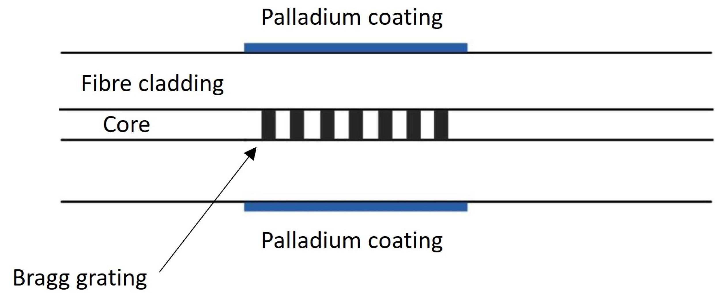
  75. Ma, G.M.; Jiang, J.; Li, C.R.; Song, H.T.; Luo, Y.T.; Wang, H.B. Pd/Ag coated fiber Bragg grating sensor for hydrogen monitoring in power transformers. Rev. Sci. Instrum. 2015, 86, 045003. [Google Scholar] [CrossRef]
  76. Jiang, J.; Ma, G.M.; Li, C.R.; Song, H.T.; Luo, Y.T.; Wang, H.B. Highly Sensitive Dissolved Hydrogen Sensor Based on Side-Polished Fiber Bragg Grating. IEEE Photonics Technol. Lett. 2015, 27, 1453–1456. [Google Scholar] [CrossRef]
  77. Luo, Y.T.; Wang, H.B.; Ma, G.M.; Song, H.T.; Li, C.; Jiang, J. Research on High Sensitive D-Shaped FBG Hydrogen Sensors in Power Transformer Oil. Sensors 2016, 16, 1641. [Google Scholar] [CrossRef] [PubMed]
  78. Liao, W.; Chen, Z.; Xie, Y. Research on Long-term Reliability of Pd/Ag Fiber Bragg Grating Hydrogen Sensor. In Proceedings of the ECITech 2022, The 2022 International Conference on Electrical, Control and Information Technology, Kunming, China, 25–27 March 2022; pp. 1–4. [Google Scholar]
  79. N’cho, J.S.; Fofana, I. Review of Fiber Optic Diagnostic Techniques for Power Transformers. Energies 2020, 13, 1789. [Google Scholar] [CrossRef]
  80. Jiang, J.; Ma, G. Moisture Detection with Optical Methods. In Optical Sensing in Power Transformers; Wiley Online Library: Hoboken, NJ, USA, 2021; pp. 37–64. [Google Scholar] [CrossRef]
  81. Ansari, M.A.H.; Martin, D. Feasibility of Optical Fibre Sensors for Moisture Diagnosis in Transformer Insulation. In Proceedings of the 2018 Condition Monitoring and Diagnosis (CMD), Perth, WA, Australia, 23–26 September 2018; pp. 1–6. [Google Scholar] [CrossRef]
  82. Ansari, M.A.; Martin, D.; Saha, T.K. Investigation of Distributed Moisture and Temperature Measurements in Transformers Using Fiber Optics Sensors. IEEE Trans. Power Deliv. 2019, 34, 1776–1784. [Google Scholar] [CrossRef]
  83. Ansari, M.A.; Martin, D.; Saha, T.K. Advanced Online Moisture Measurements in Transformer Insulation Using Optical Sensors. IEEE Trans. Dielectr. Electr. Insul. 2020, 27, 1803–1810. [Google Scholar] [CrossRef]
  84. Akre, S.; Fofana, I.; Yéo, Z.; Brettschneider, S.; Kung, P.; Sékongo, B. On the Feasibility of Monitoring Power Transformer’s Winding Vibration and Temperature along with Moisture in Oil Using Optical Sensors. Sensors 2023, 23, 2310. [Google Scholar] [CrossRef] [PubMed]
  85. Kisch, R.J. Using Refractive Index to Monitor Oil Quality in High Voltage Transformers. Master’s Thesis, The University of British Columbia, Vancouver, BC, Canada, 2008. [Google Scholar]
  86. Onn, B.I.; Arasu, P.T.; Al-Qazwini, Y.; Abas, A.F.; Tamchek, N.; Noor, A.S.M. Fiber Bragg grating sensor for detecting ageing transformer oil. In Proceedings of the 2012 IEEE 3rd International Conference on Photonics, Pulau Pinang, Malaysia, 1–3 October 2012; pp. 110–113. [Google Scholar] [CrossRef]
  87. Nilakanta Meitei, S.; Borah, K.; Chatterjee, S. Review on monitoring of transformer insulation oil using optical fiber sensors. Results Opt. 2023, 10, 100361. [Google Scholar] [CrossRef]
  88. Yan, G.; Zhang, A.P.; Ma, G.; Wang, B.; Kim, B.; Im, J.; He, S.; Chung, Y. Fiber-Optic Acetylene Gas Sensor Based on Microstructured Optical Fiber Bragg Gratings. IEEE Photonics Technol. Lett. 2011, 23, 1588–1590. [Google Scholar] [CrossRef]
  89. Tao, C.; Li, X.; Yang, J.; Shi, Y. Optical fiber sensing element based on luminescence quenching of silica nanowires modified with cryptophane-A for the detection of methane. Sens. Actuators B Chem. 2011, 156, 553–558. [Google Scholar] [CrossRef]
  90. Tenbohlen, S.; Jagers, J.; Vahidi, F. Standardized survey of transformer reliability: On behalf of CIGRE WG A2.37. In Proceedings of the 2017 International Symposium on Electrical Insulating Materials (ISEIM), Toyohashi, Japan, 11–15 September 2017; Volume 2, pp. 593–596. [Google Scholar] [CrossRef]
  91. Cheng, Y.; Bi, J.; Chang, W.; Xu, Y.; Pan, X.; Ma, X.; Chang, S. Proposed methodology for online frequency response analysis based on magnetic coupling to detect winding deformations in transformers. High Volt. 2020, 5, 343–349. [Google Scholar] [CrossRef]
  92. Kuhn, G.G.; de Morais Sousa, K.; da Silva, J.C.C. Dynamic Strain Analysis of Transformer Iron Core with Fiber Bragg Gratings. In Advanced Photonics 2018 (BGPP, IPR, NP, NOMA, Sensors, Networks, SPPCom, SOF); Optica Publishing Group: Washington, DC, USA, 2018; p. JTu2A.74. [Google Scholar] [CrossRef]
  93. Liu, Y.; Li, L.; Zhao, L.; Wang, J.; Liu, T. Research on a new fiber-optic axial pressure sensor of transformer winding based on fiber Bragg grating. Photonic Sens. 2017, 7, 365–371. [Google Scholar] [CrossRef]
  94. de Melo, A.G.; Benetti, D.; de Lacerda, L.A.; Peres, R.; Floridia, C.; Silva, A.d.A.; Rosolem, J.B. Static and Dynamic Evaluation of a Winding Deformation FBG Sensor for Power Transformer Applications. Sensors 2019, 19, 4877. [Google Scholar] [CrossRef] [PubMed]
  95. Monteiro, C.S.; Rodrigues, A.V.; Viveiros, D.; Linhares, C.; Mendes, H.; Silva, S.O.; Marques, P.V.S.; Tavares, S.M.O.; Frazão, O. Optical Fiber Sensors for Structural Monitoring in Power Transformers. Sensors 2021, 21, 6127. [Google Scholar] [CrossRef]
  96. Ma, G.; Liu, Y.; Li, Y.; Fan, X.; Xu, C.; Qin, W. Optical Frequency-Response Analysis for Power Transformer. IEEE Trans. Power Deliv. 2021, 36, 1562–1570. [Google Scholar] [CrossRef]
  97. Gao, S.; Liu, Y.; Li, H.; Sun, L.; Liu, H.; Rao, Q.; Fan, X. Transformer Winding Deformation Detection Based on BOTDR and ROTDR. Sensors 2020, 20, 2062. [Google Scholar] [CrossRef]
  98. Mahin, A.U.; Islam, S.N.; Ahmed, F.; Hossain, M.F. Measurement and monitoring of overhead transmission line sag in smart grid: A review. IET Gener. Transm. Distrib. 2022, 16, 1–18. [Google Scholar] [CrossRef]
  99. Chai, Q.; Luo, Y.; Ren, J.; Zhang, J.; Yang, J.; Yuan, L.; Peng, G. Review on fiber-optic sensing in health monitoring of power grids. Opt. Eng. 2019, 58, 072007. [Google Scholar] [CrossRef]
  100. CIGRE. Sustainability of Overhead Line Conductors and Fittings—Conductor Condition Assessment and Life Extension Volume 1: State of the Art; Technical Report; CIGRE: Paris, France, 2023. [Google Scholar]
  101. Liu, S.; Xiao, W.; Chen, H.; Bai, H.; Feng, Y.; Fang, X. Temperature Measurements for Transmission Lines Based on Passive Optical Sensing. Appl. Mech. Mater. 2014, 543–547, 1035–1041. [Google Scholar] [CrossRef]
  102. Barón, F.; Álvarez Botero, G.; Amortegui, F.; Pastor, D.; Varón, M. Temperature measurements on overhead lines using fiber Bragg grating sensors. In Proceedings of the 2017 IEEE International Instrumentation and Measurement Technology Conference (I2MTC), Turin, Italy, 22–25 May 2017; pp. 1–4. [Google Scholar] [CrossRef]
  103. Gangopadhyay, T.; Paul, M.; Bjerkan, L. Fiber-optic sensor for real-time monitoring of temperature on high voltage (400KV) power transmission lines. In Proceedings of the 20th International Conference on Optical Fibre Sensors, (OFS-20), Edinburgh, UK, 5–9 October 2009; p. 7503. [Google Scholar] [CrossRef]
  104. Wei, J.; Wang, Z.; Tian, B.; Tan, Z.; Nie, S.; Li, Y.; Zhang, Y.; Gong, X.; Zhu, Z.; Xiao, R. Temperature Monitoring for Overhead Transmission Line Based on Raman Distributed Optical Fiber Sensing Technology. In Proceedings of the 2022 IEEE International Conference on High Voltage Engineering and Applications (ICHVE), Chongqing, China, 25–29 September 2022; pp. 1–4. [Google Scholar] [CrossRef]
  105. Luo, J.; Hao, Y.; Ye, Q.; Hao, Y.; Li, L. Development of Optical Fiber Sensors Based on Brillouin Scattering and FBG for On-Line Monitoring in Overhead Transmission Lines. J. Light. Technol. 2013, 31, 1559–1565. [Google Scholar] [CrossRef]
  106. Fusiek, G.; Niewczas, P. Design of an optical sensor with varied sensitivities for overhead line sag, temperature and vibration monitoring. In Proceedings of the 2022 IEEE International Instrumentation and Measurement Technology Conference (I2MTC), Ottawa, ON, Canada, 16–19 May 2022; pp. 1–6. [Google Scholar] [CrossRef]
  107. Huang, Q.; Zhang, C.; Liu, Q.; Ning, Y.; Cao, Y. New type of fiber optic sensor network for smart grid interface of transmission system. In Proceedings of the IEEE PES General Meeting, Minneapolis, MN, USA, 25–29 July 2010; pp. 1–5. [Google Scholar] [CrossRef]
  108. Wydra, M.; Kisała, P.; Harasim, D.; Kacejko, P. Overhead Transmission Line Sag Estimation Using a Simple Optomechanical System with Chirped Fiber Bragg Gratings. Part 1: Preliminary Measurements. Sensors 2018, 18, 309. [Google Scholar] [CrossRef] [PubMed]
  109. Ogawa, Y.; Ichi Iwasaki, J.; Nakamura, K. A Multiplexing LoadMonitoring System of Power Transmission Lines using FiberBragg Grating. In 12th International Conference on Optical Fiber Sensors; Optica Publishing Group: Washington, DC, USA, 1997; p. OThC16. [Google Scholar] [CrossRef]
  110. Liang, S.; Yang, H.; Miao, X.; Cao, M.; Chang, M. An Overhead Conductor Weighing Sensor Based on Fiber Bragg Grating. Appl. Mech. Mater. 2013, 462–463, 32–38. [Google Scholar] [CrossRef]
  111. Mao, N.; Ma, G.; Li, C.; Li, Y.; Shi, C.; Du, Y. High sensitive FBG load cell for icing of overhead transmission lines. In Proceedings of the 2017 25th Optical Fiber Sensors Conference (OFS), Jeju, Republic of Korea, 24–28 April 2017; pp. 1–4. [Google Scholar] [CrossRef]
  112. Guoming, M.; Li, C.; Jiang, J.; Luo, Y.T.; Cheng, Y.C. A novel optical load cell used in icing monitoring on overhead transmission lines. Cold Reg. Sci. Technol. 2012, 71, 67–72. [Google Scholar] [CrossRef]
  113. Ma, G.M.; Li, C.R.; Quan, J.T.; Jiang, J.; Cheng, Y.C. A Fiber Bragg Grating Tension and Tilt Sensor Applied to Icing Monitoring on Overhead Transmission Lines. IEEE Trans. Power Deliv. 2011, 26, 2163–2170. [Google Scholar] [CrossRef]
  114. Liu, F.; Guo, L.; Deng, Y.; Wu, C.; Li, J.; Yang, X.; Wu, T.; Chen, H.; Yang, L. Application of Fiber Bragg Grating Device in Icing Monitoring System of Transmission Lines. Appl. Mech. Mater. 2014, 543–547, 1030–1034. [Google Scholar] [CrossRef]
  115. Zhang, M.; Xing, Y.; Zhang, Z.; Chen, Q. Design and Experiment of FBG-Based Icing Monitoring on Overhead Transmission Lines with an Improvement Trial for Windy Weather. Sensors 2014, 14, 23954–23969. [Google Scholar] [CrossRef]
  116. Guoming, M.; Li, Y.b.; Mao, N.; Shi, C.; Zhang, B.; Li, C. A Fiber Bragg Grating-Based Dynamic Tension Detection System for Overhead Transmission Line Galloping. Sensors 2018, 18, 365. [Google Scholar] [CrossRef]
  117. Bjerkan, L. Application of Fiber-Optic Bragg Grating Sensors in Monitoring Environmental Loads of Overhead Power Transmission Lines. Appl. Opt. 2000, 39, 554–560. [Google Scholar] [CrossRef]
  118. Hang, X.; Zhang, H.; Zhao, Y. Usability of fiber Bragg grating sensors for the fatigue life monitoring of overhead transmission lines. In Proceedings of the 2018 Condition Monitoring and Diagnosis (CMD), Perth, WA, Australia, 23–26 September 2018; pp. 1–5. [Google Scholar] [CrossRef]
  119. Zhao, L.; Huang, X. Integrated condition monitoring system of transmission lines based on fiber bragg grating sensor. In Proceedings of the 2016 International Conference on Condition Monitoring and Diagnosis (CMD), Xi’an, China, 25–28 September 2016; pp. 667–670. [Google Scholar] [CrossRef]
  120. CIGRE. State of the Art of Conductor Galloping; Technical Report; CIGRE: Paris, France, 2007. [Google Scholar]
  121. Chen, Y.; Zhang, Z.; Chen, X. Novel monitoring method of power transmission line galloping based on fiber Bragg grating sensor. Opt. Eng. 2011, 50, 114403. [Google Scholar] [CrossRef]
  122. Tan, T.; Duan, C.; Liu, X.; Fan, D.; Ye, Z.; Xie, K.; Chai, Q.; Tian, Y.; Zhang, J. Research on Monitoring the Transmission Line Tension and Galloping Based on FBG Fitting Sensor. IEEE Trans. Instrum. Meas. 2022, 71, 7008108. [Google Scholar] [CrossRef]
  123. de Nazaré, F.V.B.; Werneck, M.M. Compact Optomagnetic Bragg-Grating-Based Current Sensor for Transmission Lines. IEEE Sens. J. 2015, 15, 100–109. [Google Scholar] [CrossRef]
  124. Moghadas, A.A.; Shadaram, M. Fiber Bragg Grating Sensor for Fault Detection in Radial and Network Transmission Lines. Sensors 2010, 10, 9407–9423. [Google Scholar] [CrossRef] [PubMed]
  125. Nasir, M.; Dyśko, A.; Niewczas, P.; Booth, C.; Orr, P.; Fusiek, G. Development of power system differential protection based on optical current measurement. In Proceedings of the 2013 48th International Universities’ Power Engineering Conference (UPEC), Dublin, Ireland, 2–5 September 2013; pp. 1–4. [Google Scholar] [CrossRef]
  126. Orr, P.; Fusiek, G.; Niewczas, P.; Booth, C.D.; Dyśko, A.; Kawano, F.; Nishida, T.; Beaumont, P. Distributed Photonic Instrumentation for Power System Protection and Control. IEEE Trans. Instrum. Meas. 2015, 64, 19–26. [Google Scholar] [CrossRef]
  127. Saito, S.; Fujii, Y.; Yokoyama, K.; Ono, Y. The laser current transformer for EHV power transmission lines. IEEE J. Quantum Electron. 1966, 2, 147. [Google Scholar] [CrossRef]
  128. Silva, R.M.; Martins, H.; Nascimento, I.; Baptista, J.M.; Ribeiro, A.L.; Santos, J.L.; Jorge, P.; Frazão, O. Optical Current Sensors for High Power Systems: A Review. Appl. Sci. 2012, 2, 602–628. [Google Scholar] [CrossRef]
  129. Saleem, M.Z.; Akbar, M. Review of the Performance of High-Voltage Composite Insulators. Polymers 2022, 14, 431. [Google Scholar] [CrossRef]
  130. Std 1863–2019; IEEE Guide for Overhead AC Transmission Line Design. IEEE: Piscataway, NJ, USA, 2020; pp. 1–109. [CrossRef]
  131. Gubanski, S.; Dernfalk, A.; Andersson, J.; Hillborg, H. Diagnostic Methods for Outdoor Polymeric Insulators. IEEE Trans. Dielectr. Electr. Insul. 2007, 14, 1065–1080. [Google Scholar] [CrossRef]
  132. Burnham, J.; Baker, T.; Bernstorf, A.; de Tourreil, C.; George, J.M.; Gorur, R.; Hartings, R.; Hill, B.; Jagtiani, A.; McQuarrie, T.; et al. IEEE Task Force Report: Brittle fracture in nonceramic insulators. IEEE Trans. Power Deliv. 2002, 17, 848–856. [Google Scholar] [CrossRef]
  133. Tzimas, A.; Silva, E.D.; Rowland, S.M.; Boumecid, B.; Queen, M.; Michel, M. Asset management frameworks for outdoor composite insulators. IEEE Trans. Dielectr. Electr. Insul. 2012, 19, 2044–2054. [Google Scholar] [CrossRef]
  134. CIGRE. Review of “in Service Diagnostic Testing” of Composite Insulators; Technical Report; CIGRE: Paris, France, 1996. [Google Scholar]
  135. Luyao, Z.; Te, L.; Xiaoyu, Z.; Weiling, G.; Zhenguo, W.; Shaohe, W. Statistical Analysis of String Fracture and Core Breakdown of Composite Insulators in Zhejiang Province. In Proceedings of the 2019 IEEE Sustainable Power and Energy Conference (iSPEC), Beijing, China, 21–23 November 2019; pp. 1464–1468. [Google Scholar] [CrossRef]
  136. Chen, W.; Dong, X.; Zhu, X.; Yang, F.; Hu, X. Stress Analysis and Detection of Composite Electrical Insulators with Embedded Fiber Bragg Grating Sensors. Sens. Lett. 2012, 10, 1562–1565. [Google Scholar] [CrossRef]
  137. Trouillet, A.; Lepley, D.; Mure-Ravaud, A.; Marin, E. Integration of fibre Bragg grating strain sensors into composite electrical insulators. In Proceedings of SPIE—The International Society for Optical Engineering; SPIE: Bellingham, WA, USA, 2004. [Google Scholar] [CrossRef]
  138. Wan, X.-D.; Nan, J.; Xu, T.; Li, Y.-Q. On-line Monitoring Technology of UHV Composite Insulator Based on FBG Sensor. In Proceedings of the 2019 IEEE Sustainable Power and Energy Conference (iSPEC), Beijing, China, 21–23 November 2019; pp. 2901–2904. [Google Scholar] [CrossRef]
  139. Deng, H.; Cai, W.; Liu, C.; He, J. The feasibility of the composite insulator with fiber Bragg grating embedded in the rod. In Proceedings of the IEEE PES Innovative Smart Grid Technologies, Europe, Istanbul, Turkey, 12–15 October 2014; pp. 1–4. [Google Scholar] [CrossRef]
  140. Deng, H.; Cai, W.; Song, Y.; Liu, J.; Redman, C.; Zhuang, Q. Fiber Bragg grating monitors for thermal and stress of the composite insulators in transmission lines. Glob. Energy Interconnect. 2018, 1, 382–390. [Google Scholar] [CrossRef]
  141. Cao, H.; Hao, Y.; Zhang, Z.; Wei, J.; Yang, L. System and Method of Quasi-Distributed Fiber Bragg Gratings Monitoring Brittle Fracture Process of Composite Insulators. IEEE Trans. Instrum. Meas. 2021, 70, 6009110. [Google Scholar] [CrossRef]
  142. Wang, J.; Liang, X.; Gao, Y. Failure analysis of decay-like fracture of composite insulator. IEEE Trans. Dielectr. Electr. Insul. 2014, 21, 2503–2511. [Google Scholar] [CrossRef]
  143. Chen, W.; Tang, M. Monitoring on internal temperature of composite insulator with embedding fiber Bragg grating for early diagnosis. In Proceedings of the 2017 25th Optical Fiber Sensors Conference (OFS), Jeju, Republic of Korea, 24–28 April 2017; pp. 1–4. [Google Scholar] [CrossRef]
  144. Salem, A.A.; Abd-Rahman, R.; Al-Gailani, S.A.; Kamarudin, M.S.; Ahmad, H.; Salam, Z. The Leakage Current Components as a Diagnostic Tool to Estimate Contamination Level on High Voltage Insulators. IEEE Access 2020, 8, 92514–92528. [Google Scholar] [CrossRef]
  145. Hao, Y.; Bi, J.; Wang, Q.; Yang, L. Interface temperature evolution exposed to arc discharges occurred on the uniform moist pollution layer of composite insulators based on interface fibre Bragg gratings. High Volt. 2022, 7, 763–770. [Google Scholar] [CrossRef]
  146. Hao, Y.; Bi, J.; Wang, Q.; Wei, J.; Chen, Y.; Yang, L. Method of quasi-distributed interface fiber Bragg gratings monitoring dry band arc on the moist pollution layer of composite insulators. Electr. Power Syst. Res. 2022, 209, 107956. [Google Scholar] [CrossRef]
  147. Hao, Y.; Fu, Y.; Wei, J.; Yang, L.; Mao, G.; Yang, Z.; Li, L. Internal Temperature Detections of Contaminated Silicone Rubber Under Discharge Conditions Based on Fiber Bragg Gratings. IEEE Access 2019, 7, 161167–161174. [Google Scholar] [CrossRef]
  148. Wei, J.; Hao, Y.; Fu, Y.; Yang, L.; Gan, J.; Li, H. Experimental Study on Glaze Icing Detection of 110 kV Composite Insulators Using Fiber Bragg Gratings. Sensors 2020, 20, 1834. [Google Scholar] [CrossRef]
  149. Wei, J.; Hao, Y.; Fu, Y.; Yang, L.; Gan, J.; Yang, Z. Feasibility Study on Detecting Glaze Icing Load of Composite Insulators by Using Fiber Bragg Grating. In Proceedings of the 2019 2nd International Conference on Electrical Materials and Power Equipment (ICEMPE), Guangzhou, China, 7–10 April 2019; pp. 499–503. [Google Scholar] [CrossRef]
  150. Hao, Y.; Huang, L.; Wei, J.; Liang, W.; Pan, R.; Yang, L. The Detecting System and Method of Quasi-Distributed Fiber Bragg Grating for Overhead Transmission Line Conductor Ice and Composite Insulator Icing Load. IEEE Trans. Power Deliv. 2022, 38, 1799–1809. [Google Scholar] [CrossRef]
  151. Hao, Y.; Huang, L.; Wei, J.; Pan, R.; Zhang, W.; Yang, L. Interface quasi-distributed fibre Bragg grating positioning detection of glaze icing load on composite insulators. IET Sci. Meas. Technol. 2022, 16, 316–325. [Google Scholar] [CrossRef]
  152. Douar, M.A.; Beroual, A.; Souche, X. Degradation of various polymeric materials in clean and salt fog conditions: Measurements of AC flashover voltage and assessment of surface damages. IEEE Trans. Dielectr. Electr. Insul. 2015, 22, 391–399. [Google Scholar] [CrossRef]
  153. Ma, G.M.; Jiang, J.; Mu, R.D.; Li, C.R.; Luo, Y.T. High Sensitive FBG Sensor for Equivalent Salt Deposit Density Measurement. IEEE Photonics Technol. Lett. 2015, 27, 177–180. [Google Scholar] [CrossRef]
  154. Du, Y.; Ma, G.M.; Zhao, S.J.; Zhou, H.Y.; Liu, S.P.; Li, C.R.; Zheng, Q. A high humidity sensitive Fiber Bragg Grating for contamination measurement. In Proceedings of the 2017 IEEE Electrical Insulation Conference (EIC), Baltimore, MD, USA, 11–14 June 2017; pp. 21–25. [Google Scholar] [CrossRef]
  155. Prasad Rao, N.; Samuel Knight, G.; Mohan, S.; Lakshmanan, N. Studies on failure of transmission line towers in testing. Eng. Struct. 2012, 35, 55–70. [Google Scholar] [CrossRef]
  156. Zhang, J.; Xie, Q. Failure analysis of transmission tower subjected to strong wind load. J. Constr. Steel Res. 2019, 160, 271–279. [Google Scholar] [CrossRef]
  157. Albermani, F.; Kitipornchai, S.; Chan, R. Failure analysis of transmission towers. Eng. Fail. Anal. 2009, 16, 1922–1928. [Google Scholar] [CrossRef]
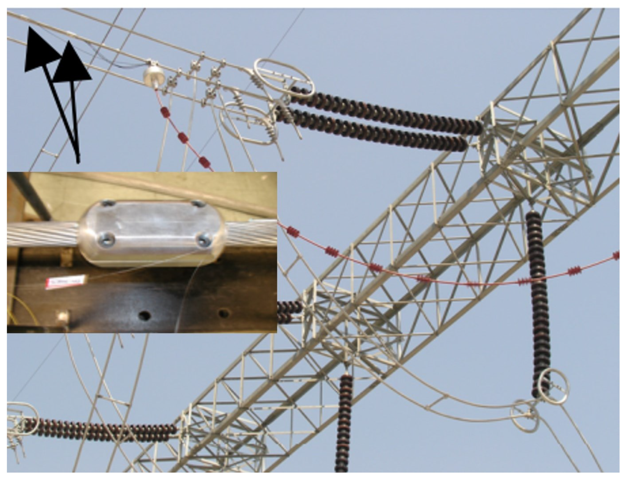
  158. Xie, K.; Lv, Z.; Zheng, X.; Tan, T.; Zhang, H.; Meng, Y.; Chai, Q.; Zhang, J.; Yang, J.; Yuan, L. Transmission line galloping induced dynamic strain measurement of an angle brace based power transmission tower by FBG sensors. In Proceedings of the 2018 IEEE International Instrumentation and Measurement Technology Conference (I2MTC), Houston, TX, USA, 1–17 May 2018; pp. 1–5. [Google Scholar] [CrossRef]
  159. Zhang, L.; Ruan, J.; du, Z.; Huang, D.; Deng, Y. Transmission line tower failure warning based on FBG strain monitoring and prediction model. Electr. Power Syst. Res. 2023, 214, 108827. [Google Scholar] [CrossRef]
  160. Xinbo, H.; Zhao, L.; Chen, Z.; Liu, C. An online monitoring technology of tower foundation deformation of transmission lines. Struct. Health Monit. 2018, 18, 147592171877457. [Google Scholar] [CrossRef]
  161. Nan, Y.; Xie, W.; Min, L.; Cai, S.; Ni, J.; Yi, J.; Luo, X.; Wang, K.; Nie, M.; Wang, C.; et al. Real-Time Monitoring of Wind-Induced Vibration of High-Voltage Transmission Tower Using an Optical Fiber Sensing System. IEEE Trans. Instrum. Meas. 2020, 69, 268–274. [Google Scholar] [CrossRef]
  162. Wang, L.; Liu, C.; Zhu, X.; Xu, Z.; Zhu, W.; Zhao, L. Active Vibration-Based Condition Monitoring of a Transmission Line. Actuators 2021, 10, 309. [Google Scholar] [CrossRef]
  163. Cao, Y.; Xue, Z.; Zhang, C.; Jia, Y.; Lu, Q.; Jiang, C. Design and Application of Online Landslide Monitoring System for Transmission Lines Corridor Based on the Optical Fiber Sensing Technology. Appl. Mech. Mater. 2014, 556–562, 3160–3163. [Google Scholar] [CrossRef]
  164. Deng, C.; Cao, Y.; Xue, Z.; Bo, X.; Li, W.; Shi, Y. A case study of landslide monitoring system for a transmission tower in Maoxian, Sichuan China. In Proceedings of the 2017 IEEE 9th International Conference on Communication Software and Networks (ICCSN), Guangzhou, China, 6–8 May 2017; pp. 1516–1519. [Google Scholar] [CrossRef]
  165. Duan, C.; Zhang, H.; Li, Z.; Tian, Y.; Chai, Q.; Yang, J.; Yuan, L.; Zhang, J.; Xie, K.; Lv, Z. FBG Smart Bolts and Their Application in Power Grids. IEEE Trans. Instrum. Meas. 2020, 69, 2515–2521. [Google Scholar] [CrossRef]
  166. Ren, L.; Feng, T.; Ho, M.; Jiang, T.; Song, G. A smart “shear sensing” bolt based on FBG sensors. Measurement 2018, 122, 240–246. [Google Scholar] [CrossRef]
  167. Vahedy, V. Polymer insulated high voltage cables. IEEE Electr. Insul. Mag. 2006, 22, 13–18. [Google Scholar] [CrossRef]
  168. CIGRE. Condition Evaluation and Lifetime Strategy of HV Cable Systems; Technical Report; CIGRE: Paris, France, 2023. [Google Scholar]
  169. Goehlich, L.; Donazzi, F.; Gaspari, R. Monitoring of HV cables offers improved reliability and economy by means of ‘power sensors’. Power Eng. J. 2002, 16, 103–110. [Google Scholar] [CrossRef]
  170. Jie, X.; Zhi-bin, L.; Qi-tao, H.; Chang, L. A new packaged FBG sensor for underground cable temperature monitoring. In Proceedings of the 2017 IEEE 2nd Advanced Information Technology, Electronic and Automation Control Conference (IAEAC), Chongqing, China, 25–26 March 2017; pp. 1789–1793. [Google Scholar] [CrossRef]
  171. Gan, W.; Wang, Y. Application of the distributed optical fiber grating temperature sensing technology in high-voltage cable. In Proceedings of the 2011 International Conference on Electronic & Mechanical Engineering and Information Technology, Harbin, China, 12–14 August 2011; Volume 9, pp. 4538–4541. [Google Scholar] [CrossRef]
  172. Wang, Z.; Cao, M.; Wang, D.D.; Zhang, S.; Li, C.; Li, Y.; Li, X. On-Line Monitoring of Cable Trench and Cable Pit by Using Metal Armored FBG Temperature Sensors. Int. J. Smart Grid Clean Energy 2013, 2, 119–124. [Google Scholar] [CrossRef]
  173. Ghaderi, A.; Mingotti, A.; Lama, F.; Peretto, L.; Tinarelli, R. Effects of Temperature on MV Cable Joints Tan Delta Measurements. IEEE Trans. Instrum. Meas. 2019, 68, 3892–3898. [Google Scholar] [CrossRef]
  174. Kim, H.; Lee, M.; Jung, W.S.; Oh, S.H. Temperature monitoring techniques of power cable joints in underground utility tunnels using a fiber Bragg grating. ICT Express 2022, 8, 626–632. [Google Scholar] [CrossRef]
  175. Kawai, T.; Takinami, N.; Chino, T.; Amano, K.; Watanabe, K.; Nakamura, Y.; Shiseki, N. A new approach to cable fault location using fiber optic technology. I. IEEE Trans. Power Deliv. 1995, 10, 85–91. [Google Scholar] [CrossRef]
  176. Chen, Y.; Wang, S.; Hao, Y.; Yao, K.; Li, H.; Jia, F.; Shi, Q.; Yue, D.; Cheng, Y. The 500kV Oil-filled Submarine Cable Temperature Monitoring System Based on BOTDA Distributed Optical Fiber Sensing Technology. In Proceedings of the 2020 International Conference on Sensing, Measurement & Data Analytics in the era of Artificial Intelligence (ICSMD), Xi’an, China, 15–17 October 2020; pp. 180–183. [Google Scholar] [CrossRef]
  177. Wu, X.; Li, R.; Ni, H.; Ding, P.; Li, X.; Zhou, X.; Cheng, Y.; Yu, H. Integrated Detection of Temperature and Partial Discharge on Cables Based on FBG. In Proceedings of the 2019 2nd International Conference on Electrical Materials and Power Equipment (ICEMPE), Guangzhou, China, 7–10 April 2019; pp. 385–389. [Google Scholar] [CrossRef]
  178. kim, h.; Park, S.W.; Yeo, C.; Kang, H.S.; Park, H.J. Thermal analysis of 22.9-kV crosslinked polyethylene cable joint based on partial discharge using fiber Bragg grating sensors. Opt. Eng. 2021, 60, 034101. [Google Scholar] [CrossRef]
  179. Du, C.; Kong, D.; Xu, C. Development of a Fault Detection Instrument for Fiber Bragg Grating Sensing System on Airplane. Micromachines 2022, 13, 882. [Google Scholar] [CrossRef]
  180. Ralf, A. Optical Current Sensors for High Power Systems: A Review. Elektrotech. Inftech. 2021, 130, 646–647. [Google Scholar] [CrossRef]
Figure 1. Block diagram of a typical fibre optic sensing system.
Energies 16 06709 g001
Figure 2. Structure of the FBG sensor [7].
Energies 16 06709 g002
Figure 3. Principle of operation of the FBG sensor [15].
Energies 16 06709 g003
Figure 4. FBG sensor in PTFE protective packaging for temperature monitoring inside transformer [31].
Energies 16 06709 g004
Figure 5. Setup for tunable laser-based interrogation for detection of acoustic waves generated by PD.
Energies 16 06709 g005
Figure 6. Comparison of tunable laser-based interrogation between FBG and phase-shifted FBG [45].
Energies 16 06709 g006
Figure 7. Typical structure of FBG-based hydrogen sensor [71].
Energies 16 06709 g007
Figure 8. FBG temperature sensor installed on 400 kV line, Kolkata [103].
Energies 16 06709 g008
Figure 9. FBG strain sensor clamped to 110 kV line for sag monitoring [108].
Energies 16 06709 g009
Figure 11. Composite insulator with FBG sensor arrays embedded for icing monitoring [148].
Energies 16 06709 g011
Figure 12. Temperature monitoring of cable joint using FBG sensor [174].
Energies 16 06709 g012
Figure 13. Summary of current technology readiness levels of FBG sensors for various parameters associated with HV asset monitoring. Sensors currently in deployment stage (green), development stage (yellow), research stage (orange).
Energies 16 06709 g013
Disclaimer/Publisher’s Note: The statements, opinions and data contained in all publications are solely those of the individual author(s) and contributor(s) and not of MDPI and/or the editor(s). MDPI and/or the editor(s) disclaim responsibility for any injury to people or property resulting from any ideas, methods, instructions or products referred to in the content.

