1. Introduction
This study discusses the resonance characteristics of the LLC resonant half-bridge converter for the fast charging of batteries of personal mobility devices and smart battery charging. Recently, a new type of transportation that can accomplish tens of kilometers of travel using an AC 220 V battery has been realized.
Particularly, the new means of transportation, including electric wheelchairs, electric bicycles, electric motorcycles, electric wheels, hoverboards, segways, and micro electric vehicles, basically does not generate pollution or fine dust, such as carbon (
) and nitrogen (
). As well as this advantage, it is based on a simple payment method using a smart phone and a location-based global positioning system [
1,
2].
Lee et al. analyzed and compared an asymmetric half-bridge (AHB) converter, a two-transistor forward converter, and an active clamp forward converter. They determined that among the three topologies, the AHB converter with the smallest current flowing through the switch, diode, and inductor of the converter is the most efficient [
3].
Yong et al. analyzed and compared the topologies of an AHB converter and an LLC resonant converter in terms of the conduction and switching loss of the primary side of the transformer. They found that the efficiency of the LLC resonant converter is about 2~3% higher than that of the AHB converter [
4].
Lu et al. [
5] and Choi [
6] analyzed the series resonance characteristics of LLC resonant converters, and Beiranvand et al. investigated the optimal design method of LC–LLC resonant converters that are suitable for large output voltage and load fluctuations [
7].
Gu et al. studied an LLC series resonant converter based on a three-level topology suitable for high voltage input and high power output [
8]. Yong et al. proposed a magnetic-type LLC resonant converter [
9].
Kim et al. proposed LLC resonance on the secondary side of a transformer for the transformation of various resonance methods in relation to the LLC resonance type [
10].
Chen et al. employed LLC resonance in a bidirectional converter [
11], Cheng et al. analyzed the LLC parallel resonance method [
12], and Cheng et al. analyzed the LLCC parallel resonance method [
13].
Recently, studies on the topology suitable for high current loads have been actively conducted. Feng et al. determined that the on-resistance (
) of the switch is smaller than the voltage drop (V
D) of the rectifier diode on the secondary side of the transformer, resulting in a low voltage and high current output. Additionally, they studied a suitable synchronous-rectifier-based LLC converter [
14].
Lin et al. proposed an LLC converter based on a current doubler rectifier circuit [
15], and Mishima et al. proposed a full-bridge-based converter with four switches for large power conversion [
16]. Bhat et al. designed a bridge circuit with six switches [
17].
Yi and Moon proposed a power supply wherein two LLC resonant converters operate in parallel and perform interleaved operations [
18], and Gu et al. proposed a voltage doubler circuit that is suitable for the high voltage output of an LLC converter [
19].
To reduce the switching loss of an LLC resonant converter, Mishima et al. proposed the zero current switching (ZCS) method based on the arrangement of an active clamp circuit, wherein an auxiliary switch and auxiliary diode are placed in parallel with the main switch [
20]. Huang studied operating waveform for LLC resonant converter according to the resonant frequency [
21], and Han et al. analyzed efficiency of the LLC resonant converter according to the resonant frequency [
22].
Various studies related to LLC resonant converters are being conducted [
23,
24,
25,
26,
27].
Through resonance characteristic analysis, this study aims to validate that fS > f0 is the most appropriate correlation in the relationship between resonant frequency (f0) and switching frequency (fS)that is suitable for the rapid charging for batteries of personal mobility devices.
The proposed smart battery charging system is technically characterized; in other words, no initial overcurrent occurs during battery charging and the battery does not charge when it is discharged or mis-wired according to the detection of the battery voltage. This study proposes a battery charging system based on battery state detection that stably performs the rapid charging of the batteries of personal mobility devices by equalizing the battery and charger voltages through a pre-charge operation.
Based on the 1.5 kW class prototype, the efficiency and suitability of the proposed converter for the rapid charging of the batteries of personal mobility devices are investigated, and the feasibility of the proposed converter is discussed through simulations and experiments.
2. Characterization of the Proposed LLC Resonant Half-Bridge Converter
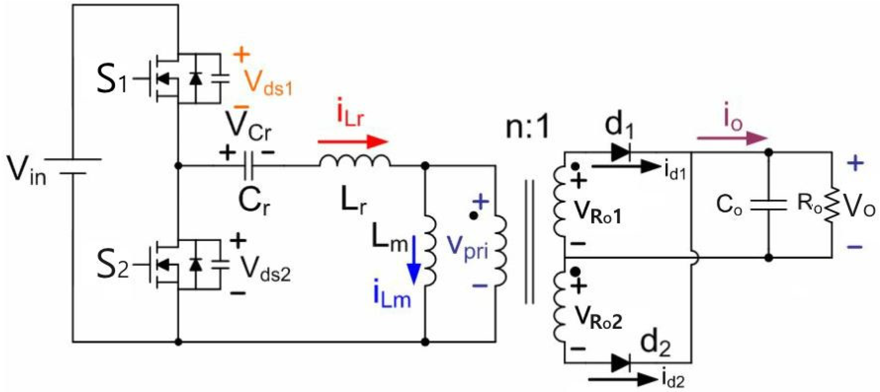
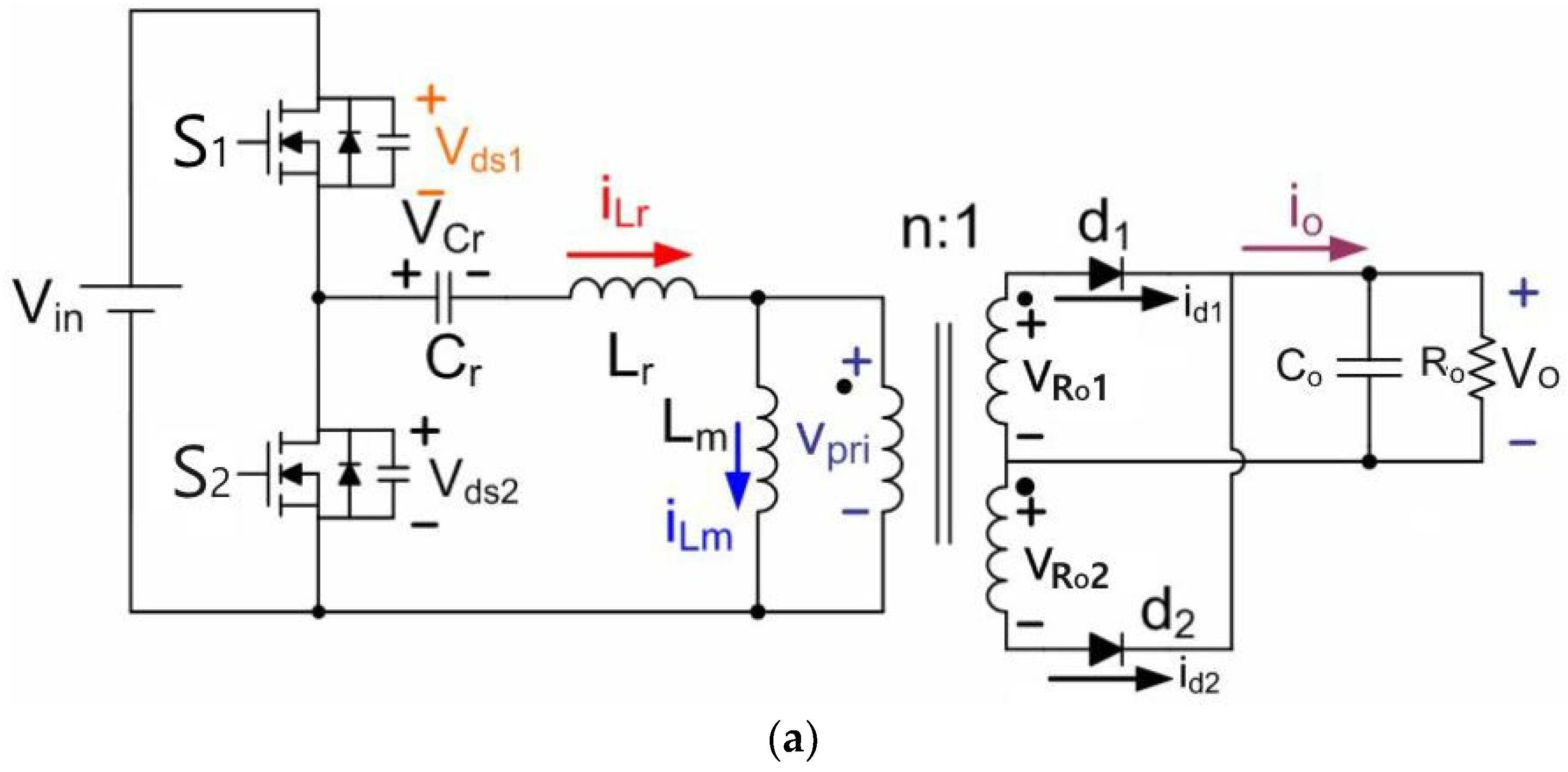
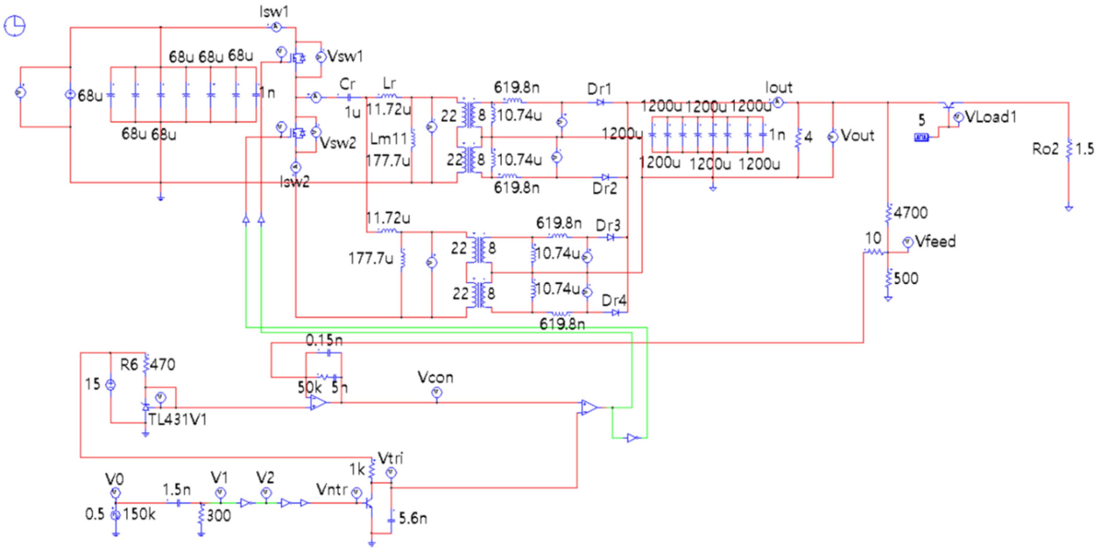
Figure 1 displays the circuit diagram of the LLC resonant AHB converter. The proposed LLC resonant AHB converter circuit comprises main switches (
), the resonant network (
), a main transformer, and secondary rectifier diodes (
). In the proposed converter, the switches and the secondary rectifier diodes operate at zero voltage switching (ZVS) and ZCS and
fS >
f0.
Since the proposed converter is based on the series resonance method, magnetizing inductance (Lm) participates in the resonance and the input/output voltage conversion ratio () can be derived based on f0.
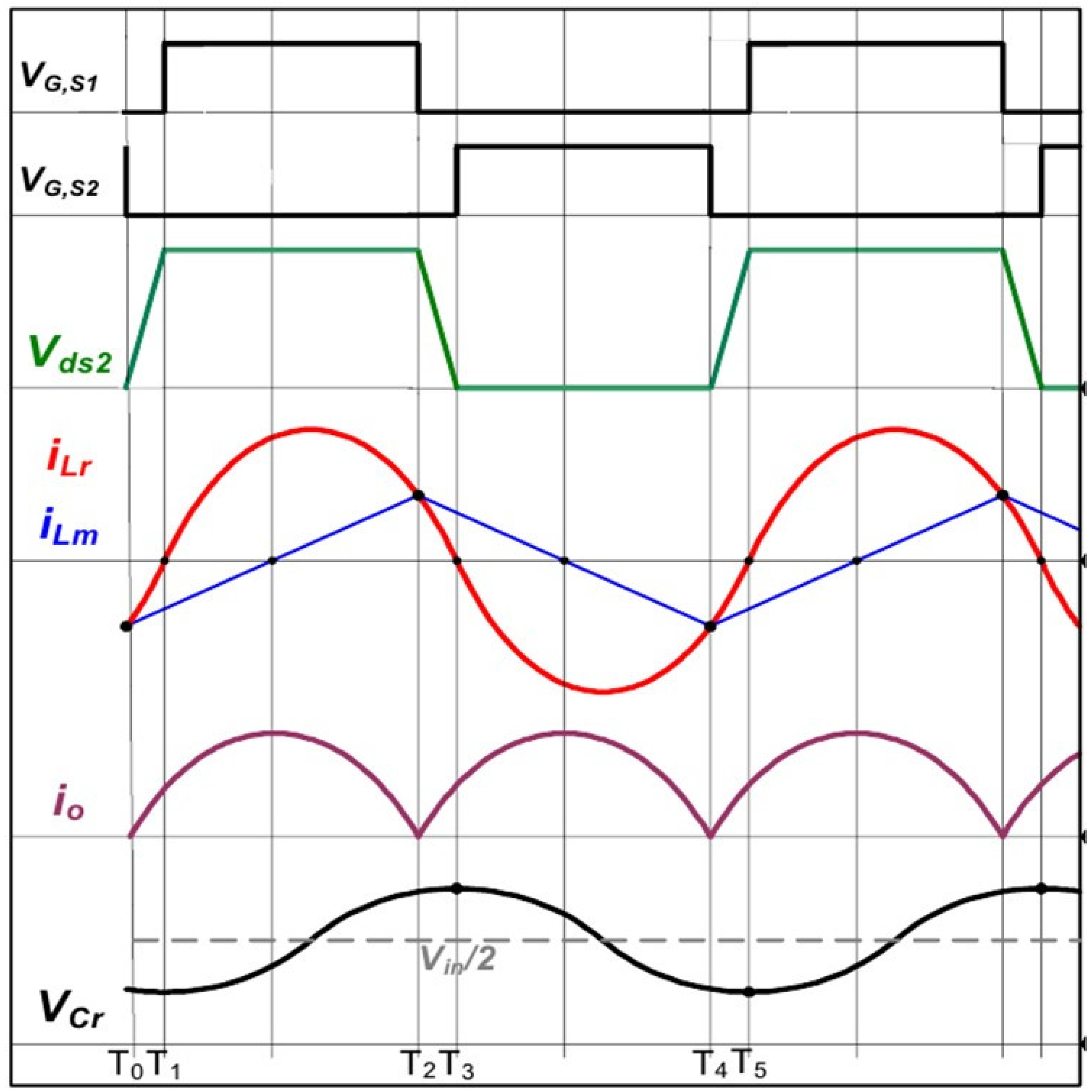
Figure 2 displays the operating waveform of the LLC resonant AHB converter that is suitable for battery charging. For the mode analysis of the LLC resonant AHB converter, the following assumptions are made.
First, the main switches and secondary rectifier diodes are ideal.
Second, the main switches comprise an ideal switch and an anti-parallel diode.
Third, the transformer considers the ideal Lm and leakage inductor (Lr).
Fourth, the output capacitor ( is very large and operates as a constant voltage source in a steady state.
Fifth, the LLC resonant converter operates in a steady state.
- (1)
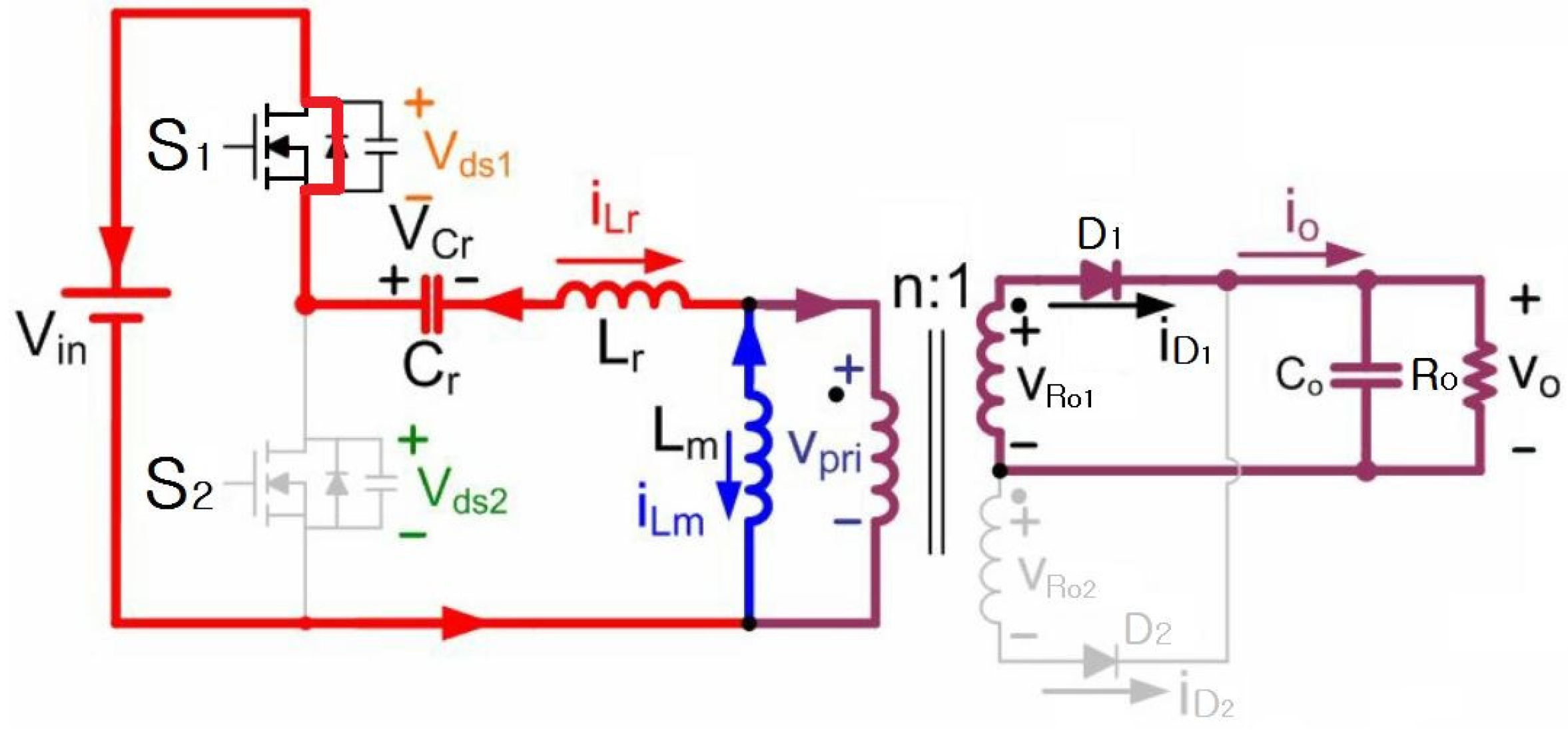
Mode 1 (T0 – T1)
Figure 3 shows the current conduction path of mode 1 and the current flow for the dead time area corresponding to the mode 1 (T
0 – T
1) section in
Figure 2. The switch S
2 is on in the period before
. The switch S
2 is turned off at
. Here, the current flowing in
is negative (
) due to the continuous flow and the resonance path
results in the flow of a negative (
)
current.
Therefore, since the voltage across switch at , the switch is turned on under the condition of ZVS; thus, the switching turn-on loss is zero (0).
The secondary rectifier diode of the transformer secondary side is conducting and the current continuously flows. The voltage across the transformer’s is (where is the winding ratio of the transformer), and the current of the transformer’s increases with a slope of s. Therefore, in mode 1, the current of is relatively larger than the current of .
- (2)
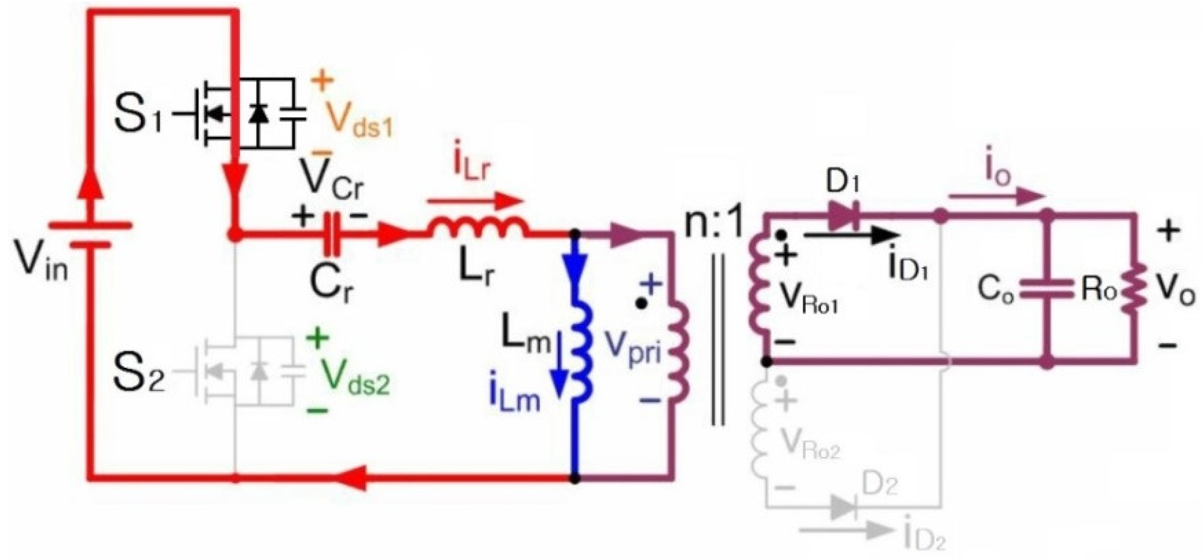
Mode 2 (T1 – T2)
Figure 4 shows the current conduction path of mode 2. It displays the current flow for the area corresponding to the mode 2 (
) section in
Figure 2. As shown in the mode 2 section waveform in
Figure 2, at
, the switch
is turned on under the condition of ZVS. Moreover, the current of
has a positive (+) value and gradually increases, and the voltage across both ends of
is applied as
. Thus, the current of the
of the transformer increases with a slope of
. During the mode 2 section,
resonance current flows and series current resonance is achieved. The rectifying diode
on the secondary side of the transformer is conducting and the current continuously flows. The remaining half-cycle follows the same process as that of mode 1.
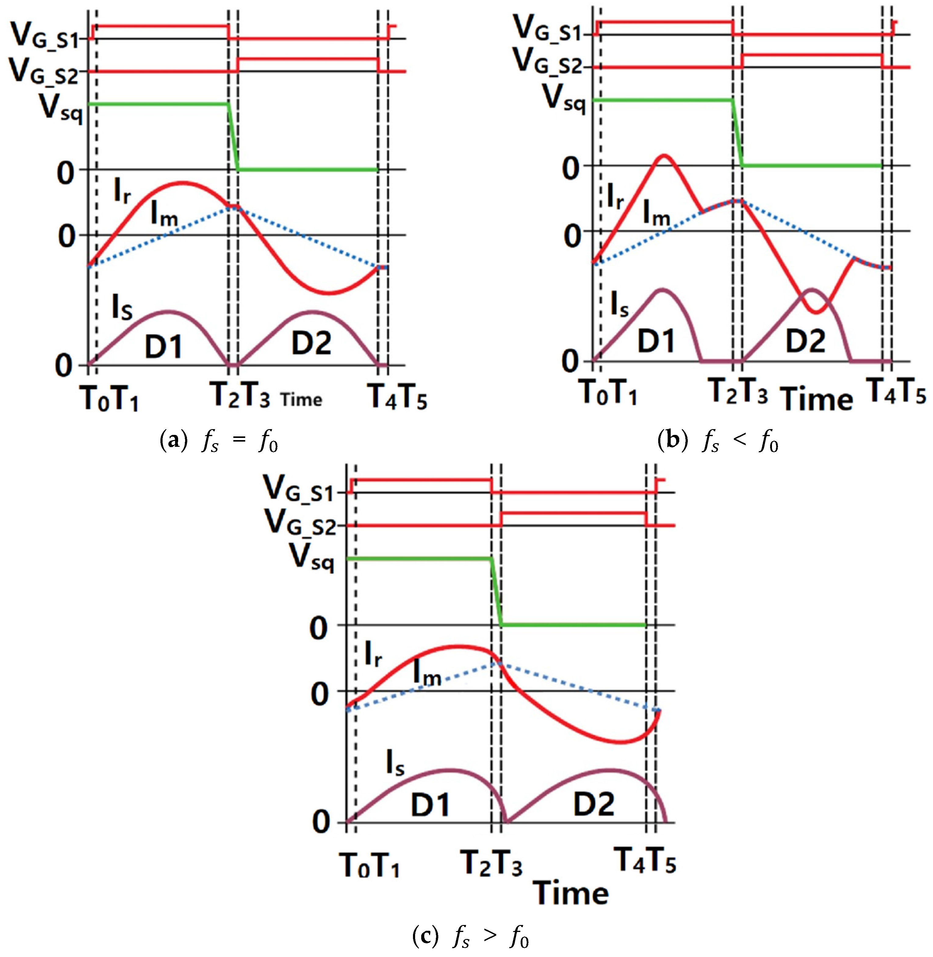
Figure 5 shows the operating waveform of the LLC resonant converter according to the resonant frequency [
21]. To date, various studies have been conducted on the design of the resonant frequency of the LLC resonant converter. For LEDs and laptops with relatively small load fluctuations, studies have been conducted to design the LLC resonant frequency as
=
or
<
[
4,
5,
6,
7,
8,
9].
For LEDs and laptops, wherein the load characteristics are almost unchanged, the LLC resonant frequency setting is designed under the condition of
=
or
<
to ensure full or heavy load, respectively. It was proposed to supply the power necessary during the heavy load condition [
4,
5,
6,
7,
8,
9]. This method exhibits excellent efficiency under full and heavy load conditions, but it is not suitable for battery charging because the battery efficiency rapidly deteriorates under light load conditions [
6,
22].
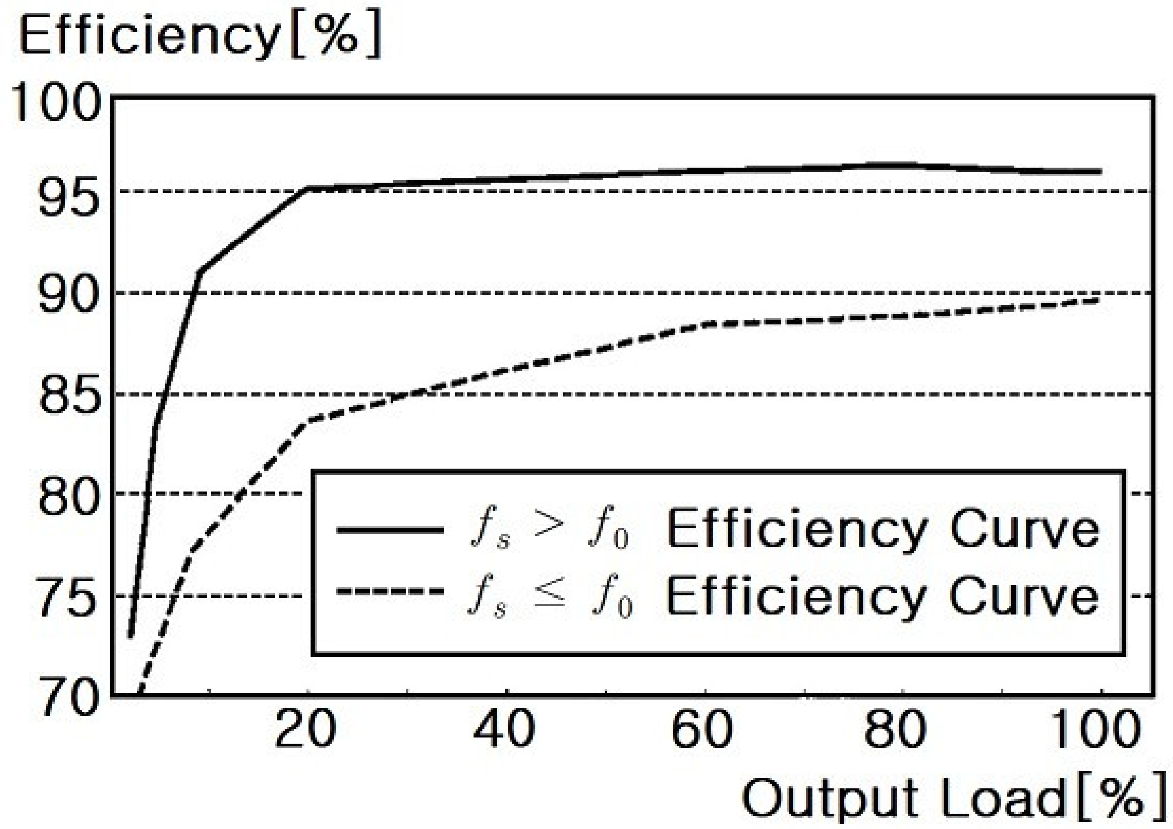
Figure 6 shows the efficiency curves at resonant frequencies
>
and
≤
[
6,
22]. As shown in
Figure 6, the efficiency of the converter at the resonant frequency is about 90% under heavy load, but the efficiency rapidly decreases under light load. At the resonant frequency
>
, the efficiency curve continuously exhibits high efficiency under full and heavy load as well as light load conditions [
6,
22].
As shown in
Figure 6, the resonant frequency
>
of the proposed AHB converter is more than 5% under the full load condition and more than 10% under the light load condition. Thus, compared to existing converters with
≤
, the proposed converter exhibits higher efficiency [
6,
22].
Therefore, herein, the LLC resonant AHB converter is applied as the circuit implementation method of a rapid charging apparatus for charging the batteries of personal mobility devices. For battery charging, a full load or heavy load is applied initially and a light load is continuously applied at the end. The validity of the proposed method was verified via comparison with the results of previous studies [
6,
22].
3. Input/Output Voltage Conversion Ratio of LLC Resonant Converter
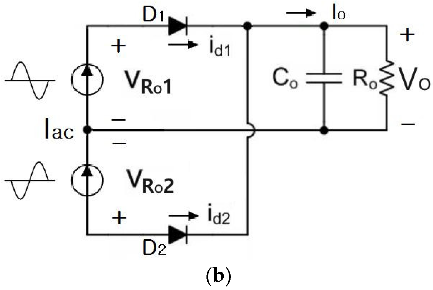
Figure 7 shows the LLC resonant AHB converter circuit and the AC equivalent circuit. From
Figure 7, the following relational expressions (1) and (2) can be derived [
6].
Therefore, based on the output voltage conversion formula, the equivalent load resistance (
) can be expressed as follows:
Considering the transformer turns the ration
, the
is obtained as
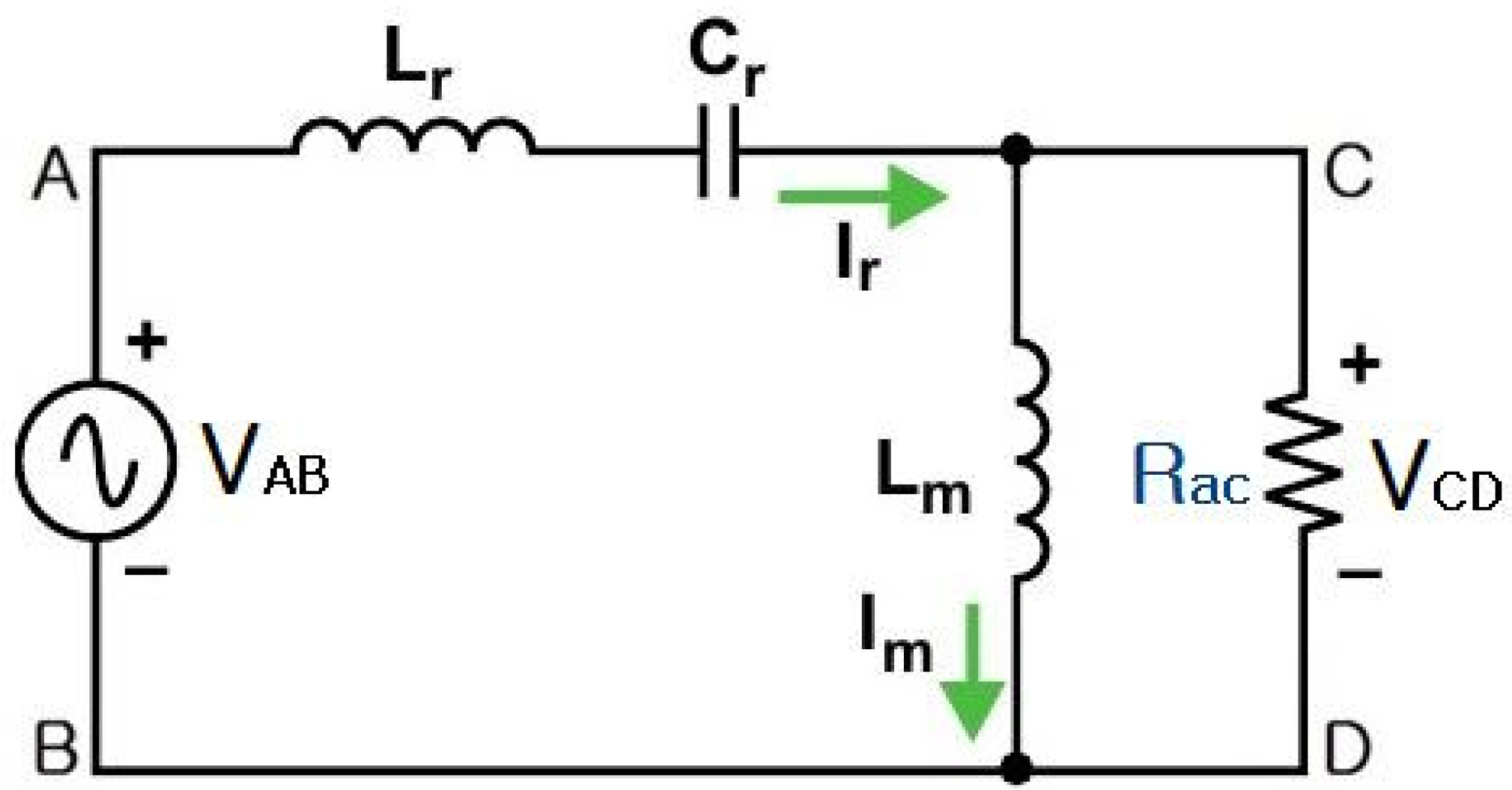
From the AC equivalent circuit of the LLC resonant converter shown in
Figure 8, the impedances of
,
, and
can be defined as follows.
Impedance of :
Impedance of :
Impedance of :
Based on the impedances defined above, the voltage ratio between the input (
) and output (
) of the LLC resonant converter (
Figure 8) can be expressed as Equations (5)–(8).
From Equation (10), the following can be defined.
- -
Quality factor:
- -
Resonant angular frequency:
- -
Normalized angular frequency:
- -
Normalized frequency:
Subsequently, the total voltage ratio (
) of the input and output including the secondary rectifier diode can be expressed as Equations (11) and (12).
where
The final
can be expressed as follows:
4. Analysis of Resonance Characteristics of LLC Resonant Converter
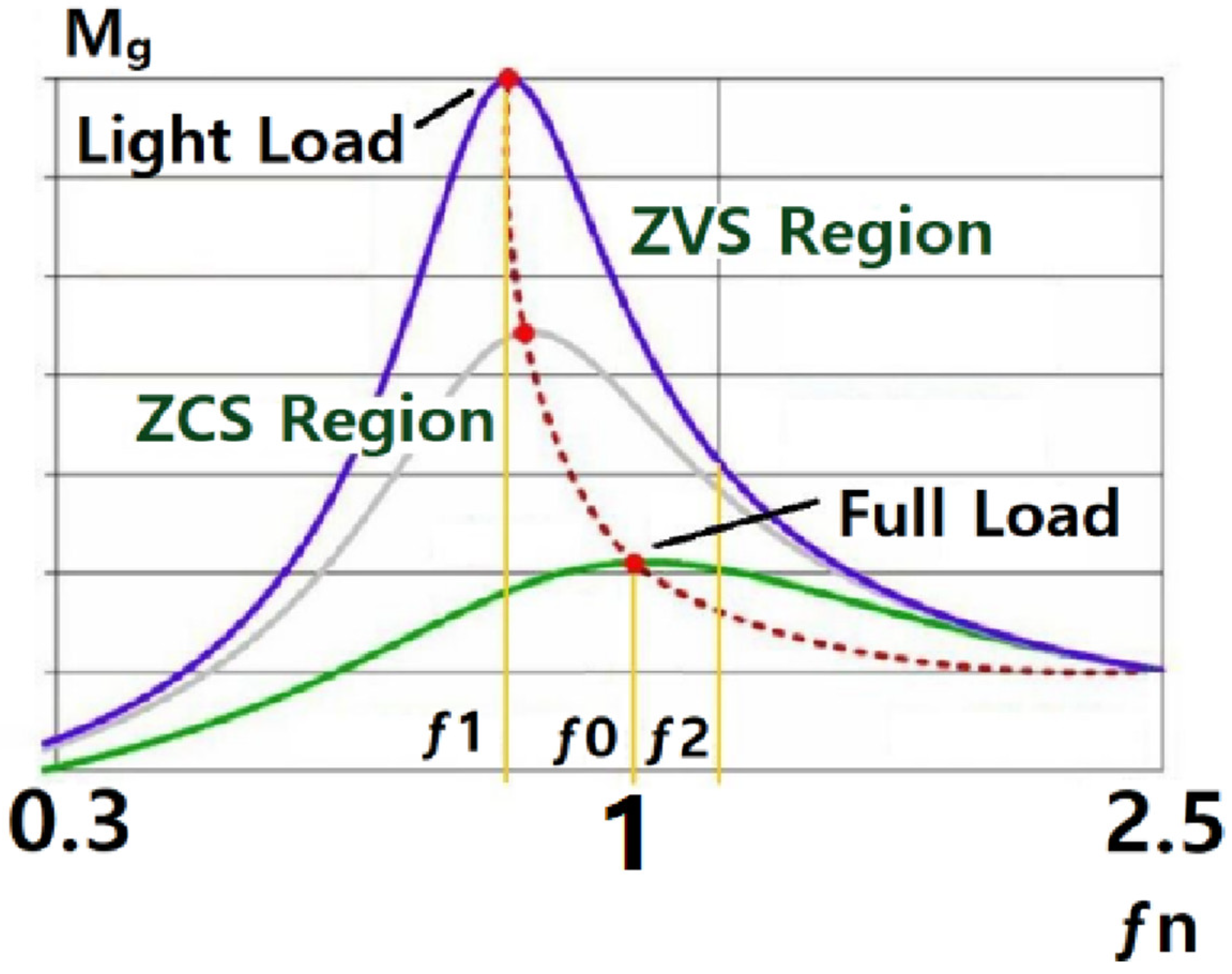
Figure 9 shows the voltage gain curve of the LLC resonant converter versus the frequency.
This figure shows the
value when the normalized frequency
is between 0.3 and 2.5. As shown in
Figure 9, for an LLC resonant converter, the reference frequency to be controlled can be defined in different ways considering the resonance characteristics. Generally, when the
of the main switch in an LLC resonant converter operates below the
.
When an LLC resonant converter operates in the ZCS region and operates above
, the switching operation is performed in the ZVS region [
6,
22].
As described above, if the LLC resonant converter is designed under the condition of
or
, the efficiency under full and heavy load conditions is excellent, but it is not suitable for lithium-ion battery chargers because the efficiency under light load conditions rapidly decreases [
10].
In a rapid charger for battery charging, operating
under the condition
is desirable, as it yields excellent efficiency in the entire load range and greatly reduces the circulating current of the resonant circuit [
22].
In this study, considering the and conditions for the proposed LLC resonant AHB converter and the input and output according to the frequency at each load, was simulated using MATLAB Version 9.4.
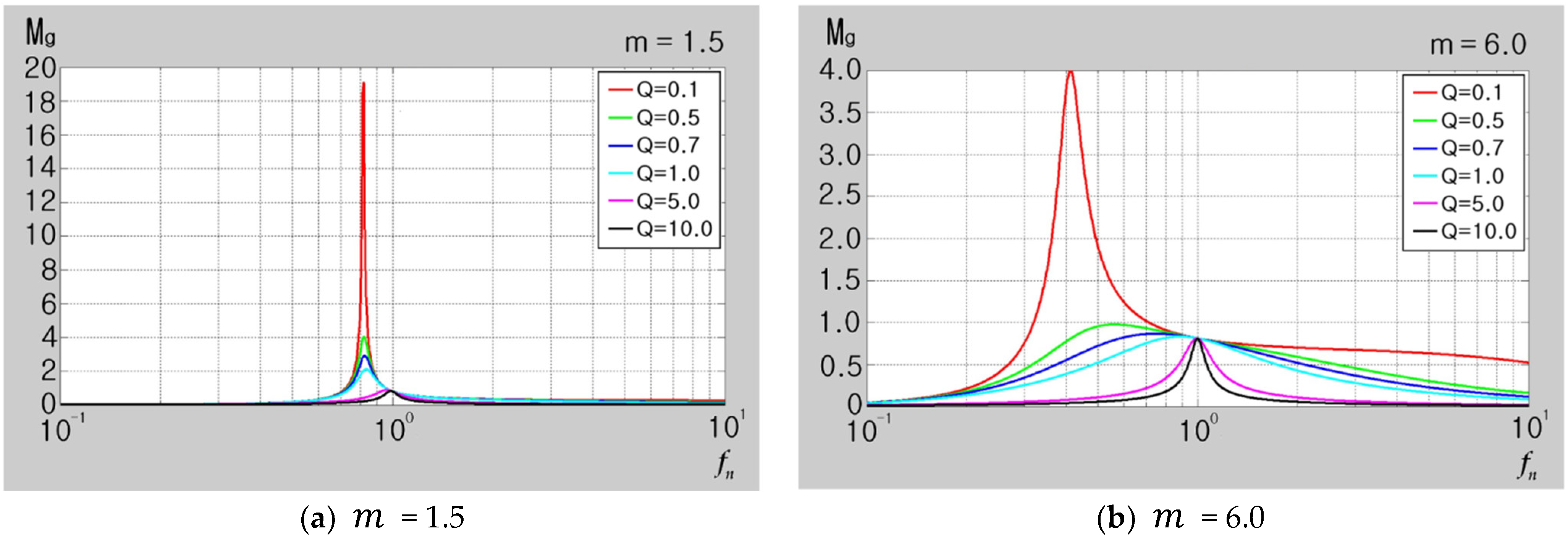
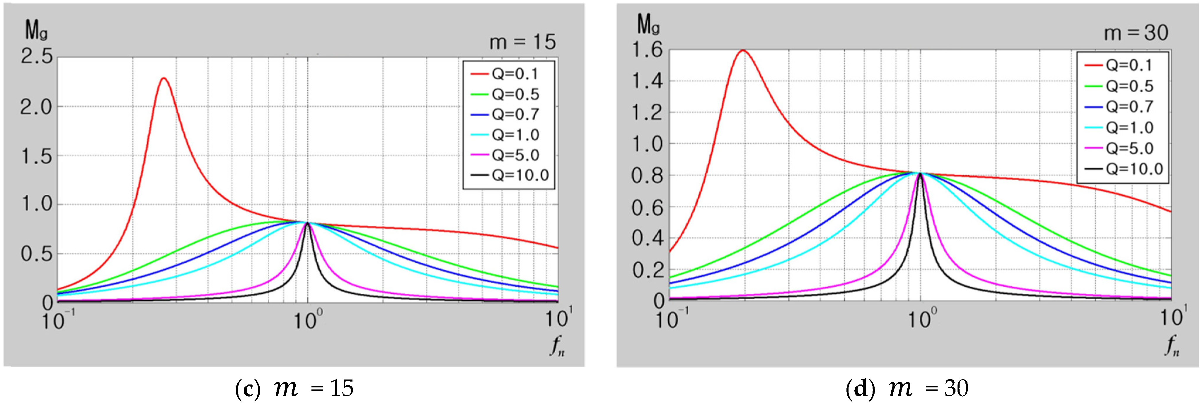
Figure 10 shows the MATLAB simulation results.
In
Figure 10, the
values obtained under the full and light load conditions in the LLC resonant converter are compared.
As seen in
Figure 10, when the m value is designed to be small, the change in total voltage gain (Mg) is large between light load and full load. And when the m value is designed to be large, the change in total voltage gain (Mg) is small.
In addition, as the Q value decreases, the load increases and the total voltage gain (Mg) increases, and as the Q value increases, the load decreases and the total voltage gain (Mg) decreases.
5. Smart Battery Charging System
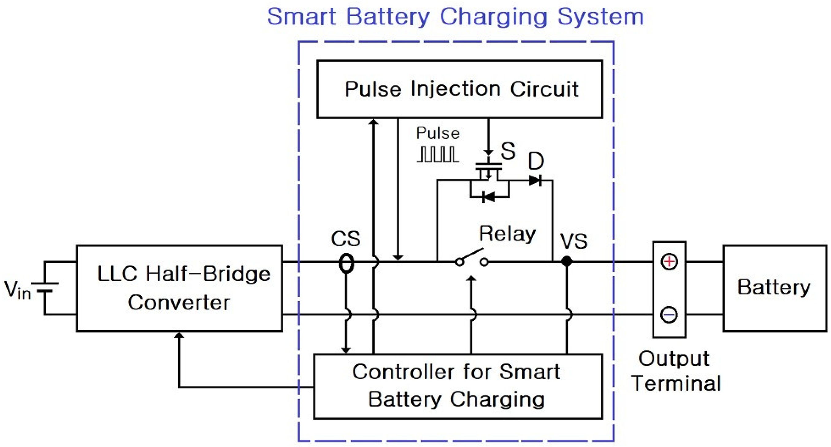
Figure 11 shows the smart battery charging system located at the output stage of the LLC AHB converter.
The smart battery charging system detects the battery connection through the following process:
- (1)
Detect the (+) voltage of the battery through the voltage sensor (VS).
- (2)
Inject a 15 V, 0.1 Hz pulse into the (+) terminal of the battery.
- (3)
Compare whether the maximum voltage of the pulse is greater than or equal to the minimum voltage of the battery.
- (4)
Check whether the current flowing through the battery is 0.5 A through the switch (S) and diode (D).
- (5)
Check whether the output voltage of the LLC half-bridge converter and the voltage of the battery are equal.
- (6)
Check whether the output voltage of the LLC half-bridge converter and the voltage of the battery are the same.
- (7)
The output current of the LLC half-bridge converter gradually increases, and after the maximum output current is reached, the output current gradually decreases.
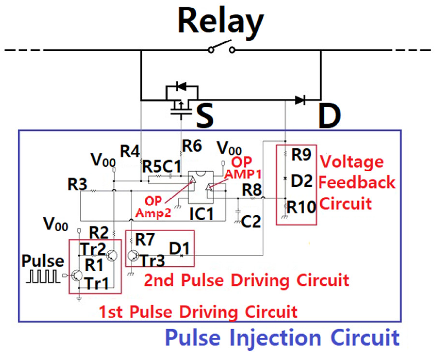
Figure 12 displays the detailed circuit diagram of the pulse injection circuit of the proposed smart battery charging system. Pulses are continuously injected through the first pulse driving circuit.
The voltage feedback circuit detects the battery voltage, and when the maximum value of the pulse voltage matches the battery voltage, the diode (D) conducts. Moreover, the second pulse driving circuit is operated by the first comparator (OP Amp1), and the switch (S) is conducted through the operation of the second comparator (OP Amp2). When the output current detects 0.5 A, the LLC half-bridge converter smartly detects whether the battery is connected to the output terminal and whether the battery voltage is normally generated.
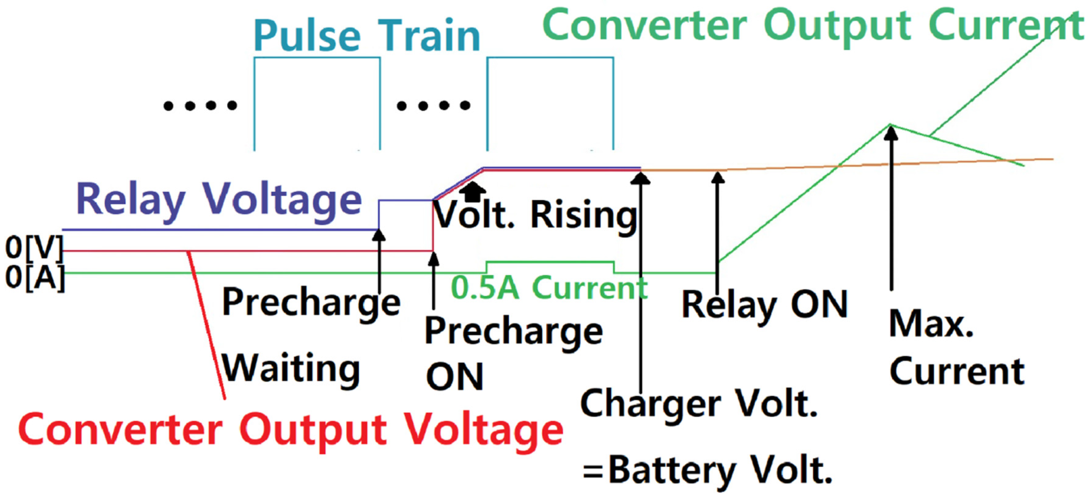
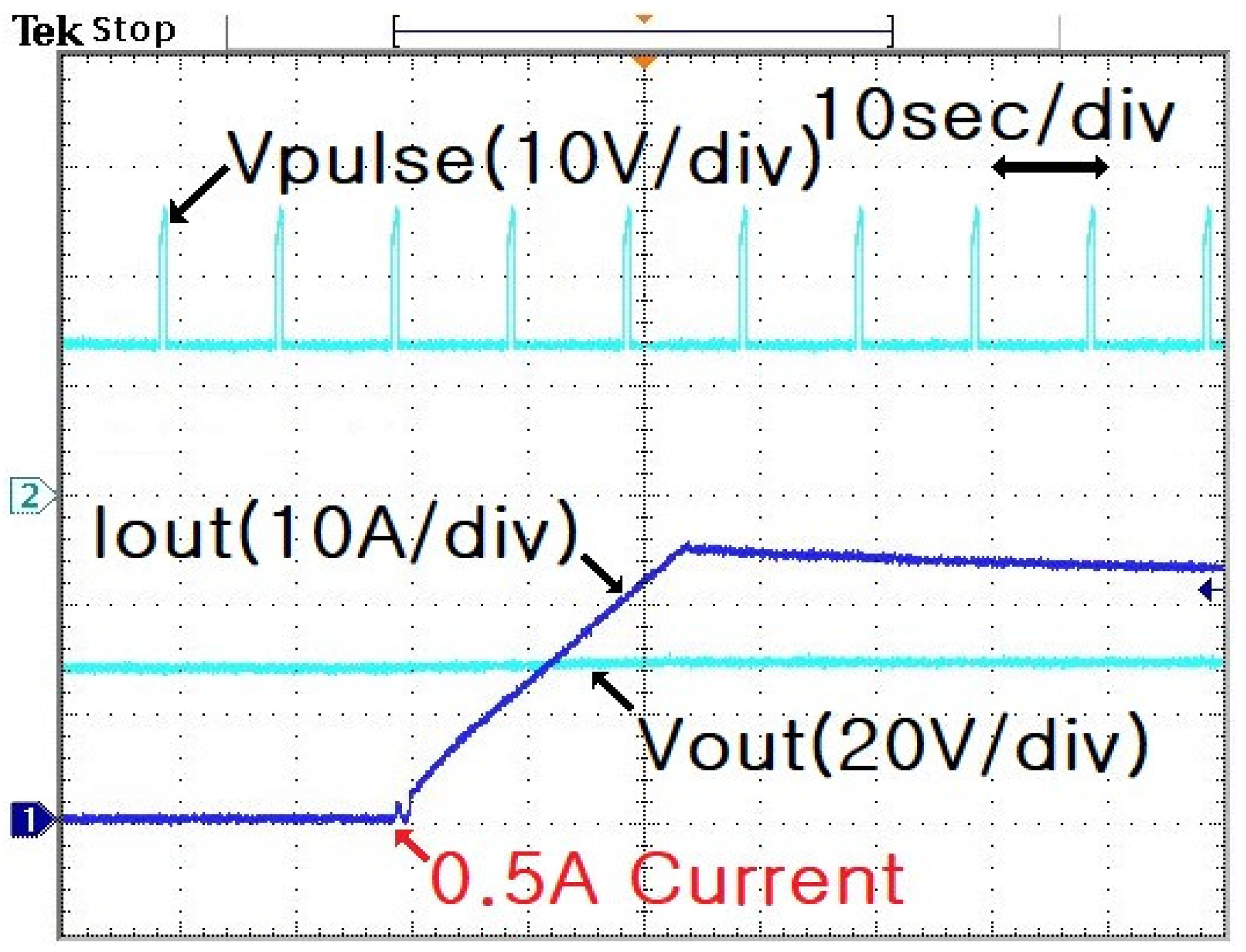
Figure 13 displays the operating waveform of the proposed smart battery charging system. The 15 V, 0.1 Hz pulse train checks whether the battery is properly connected to the output terminal. When the maximum value of the pulse voltage matches the battery voltage, an output current of 0.5 A flows while the diode (D) and switch (S) operate. Thereafter, the output voltage of the LLC half-bridge converter gradually increases, and when the output voltage becomes equal to the battery voltage, the relay is turned on.
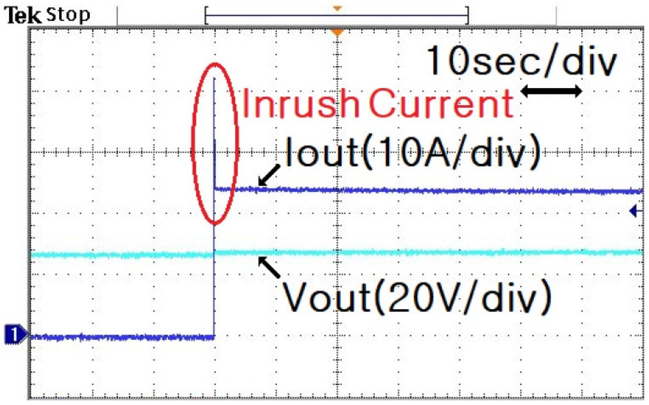
Figure 14 shows the battery charging voltage and current waveforms when no smart battery charging system is employed.
When the output voltage of the LLC half-bridge converter and the battery voltage differ, a sudden inrush current of more than 40 A is generated in the battery, which impacts the separator of the lithium-ion battery.
Figure 15 shows the battery charging voltage and current waveforms when a smart battery charging system is employed.
The proposed charging system detects the normal connection of the battery, gradually matches the output voltage of the LLC half-bridge converter with the battery voltage, and gradually increases the charging current of the lithium-ion battery by gradually increasing the output current of the battery.
Furthermore, the proposed charging system compares whether the maximum voltage of the pulse train is higher than the battery voltage when the polarity of the battery is reversed, and the relay does not operate when it is high. Thus, the proposed system is effective during mis-wiring and ensures the stable charging of the battery.
6. Simulation and Experimental Results
Table 1 presents the apparatus and circuit parameters used to manufacture the hardware for the personal mobility device rapid charging apparatus.
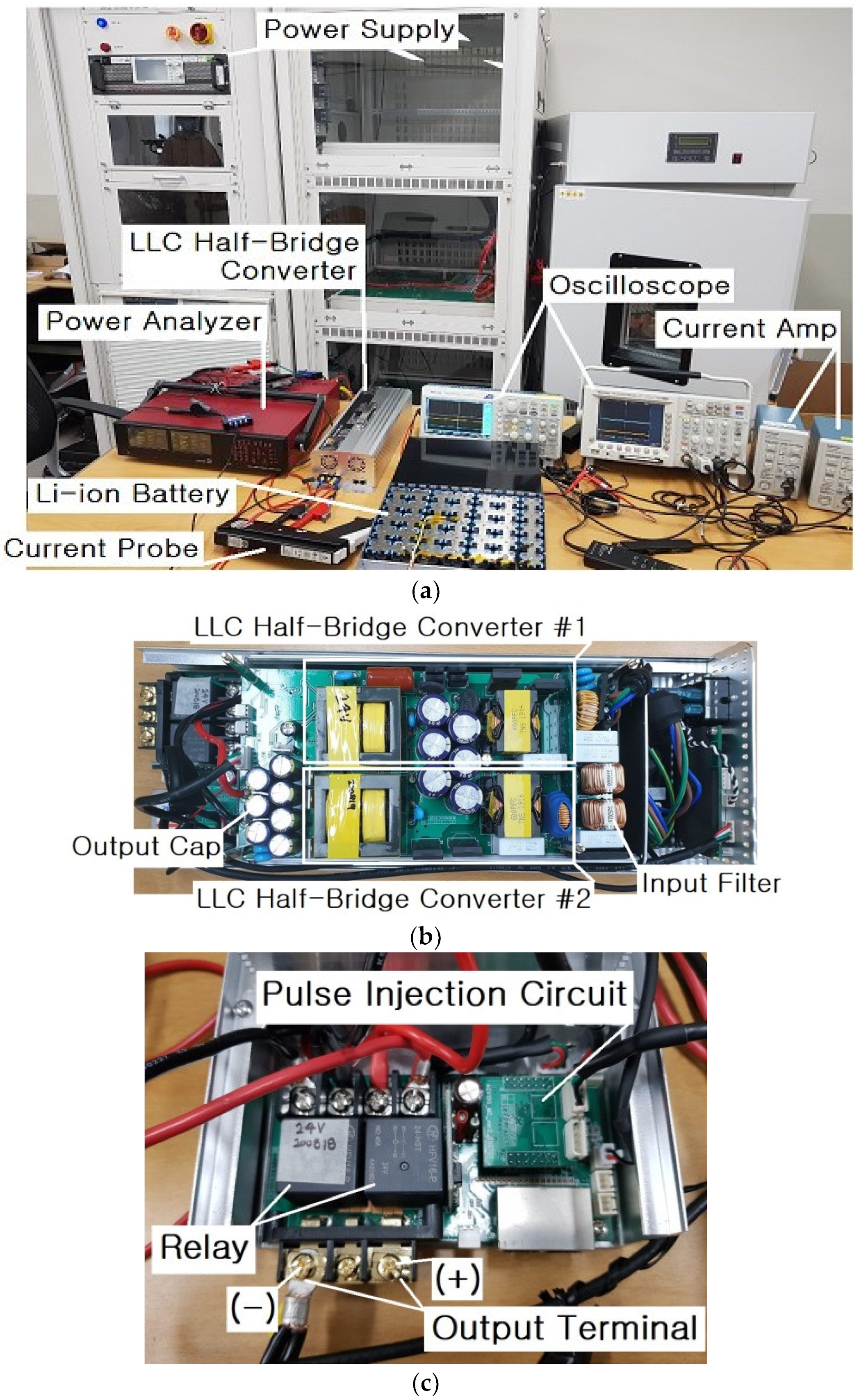
Figure 16 shows the experimental apparatus for the experiment of the proposed circuit and a picture of the manufactured LLC resonant AHB converter, and
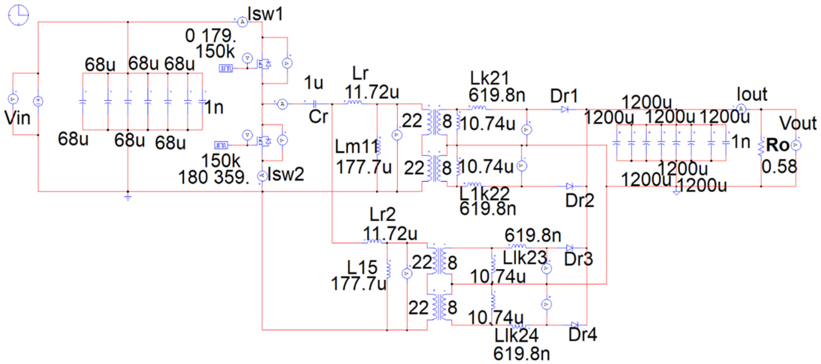
Figure 17 depicts the simulation circuit of the LLC resonant AHB converter for the proposed fast charging apparatus.
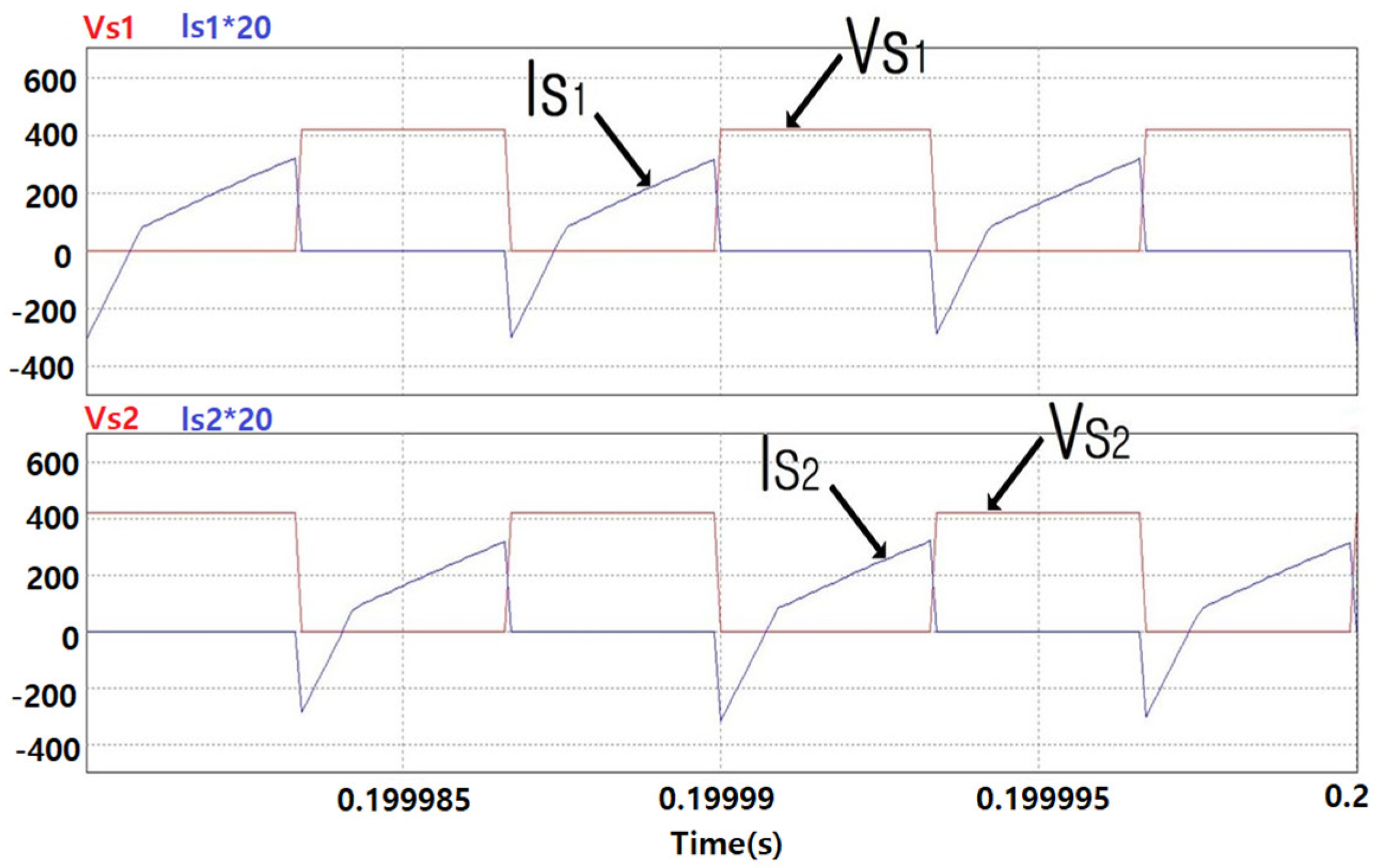
Figure 18 presents the voltage and current simulation waveforms of the upper and lower main switches (
, respectively).
Figure 18 shows that both
operate stably with ZVS.
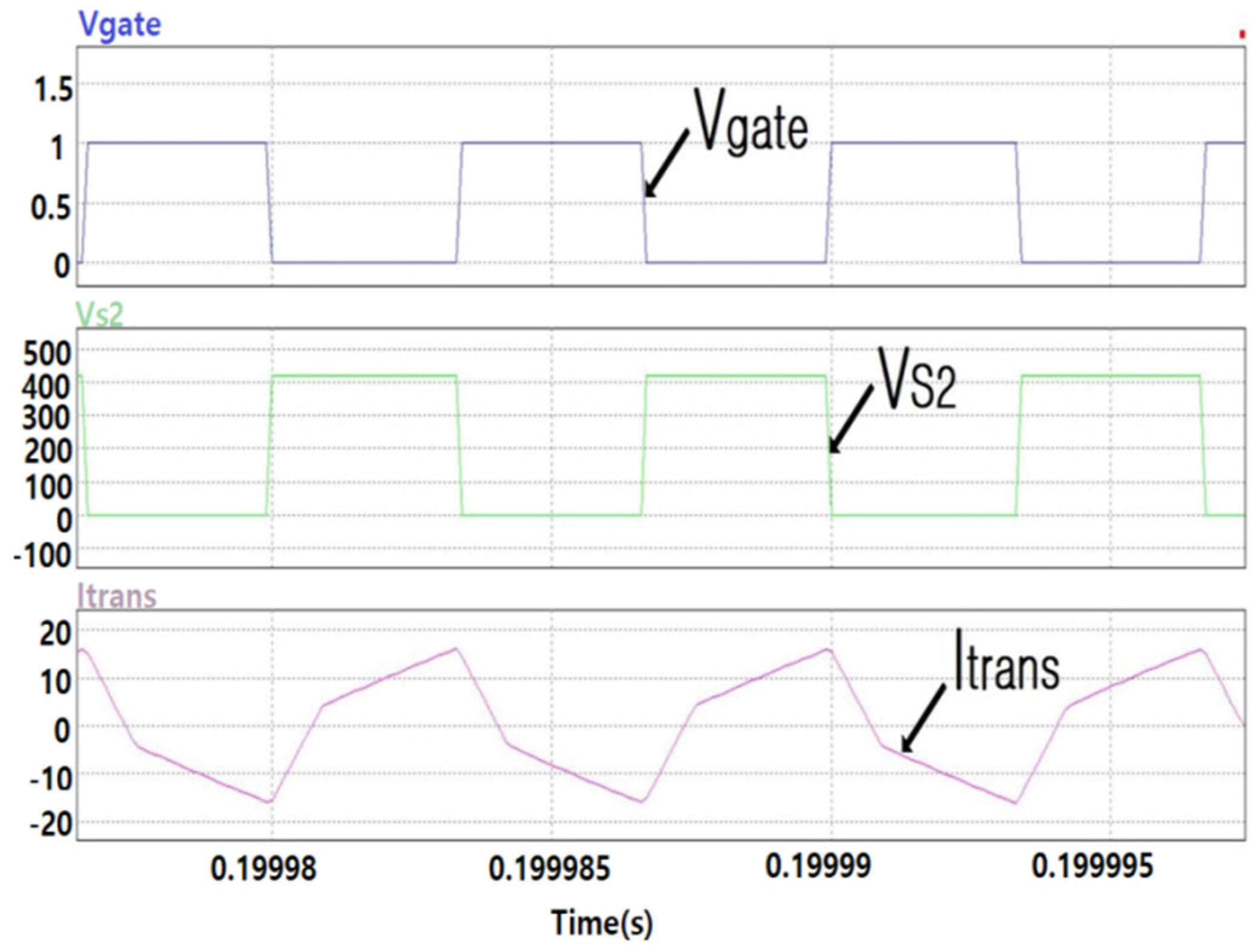
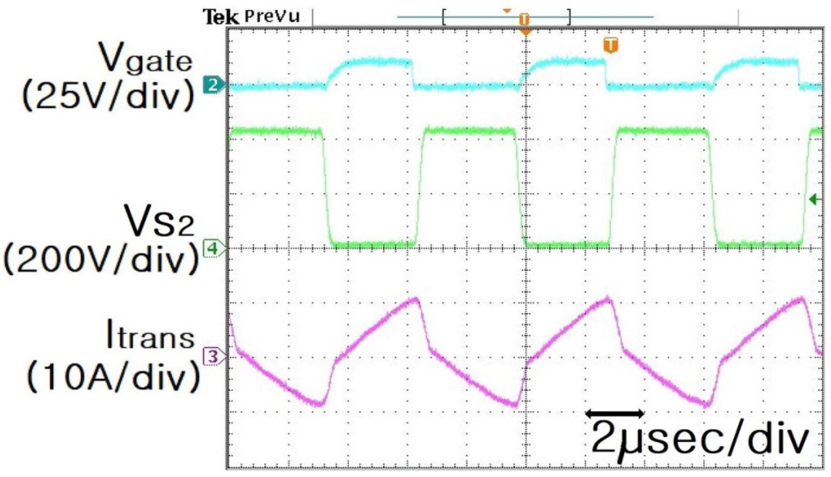
Figure 19 and
Figure 20 show the PSIM simulated and experimental waveforms of the gate signal (
), low-side switch voltage (
), and transformer current (
).
Comparing the voltage and current waveforms in
Figure 19 and
Figure 20, the shapes of the waveforms generally match. Thus, the simulations and experiments confirm that
operates under the condition of
.
Furthermore, the ZVS operation is stably performed without a voltage spike during operation of .
Figure 21 displays the simulation circuit of the LLC resonant half-bridge converter for feedback simulation using PSIM simulation, and
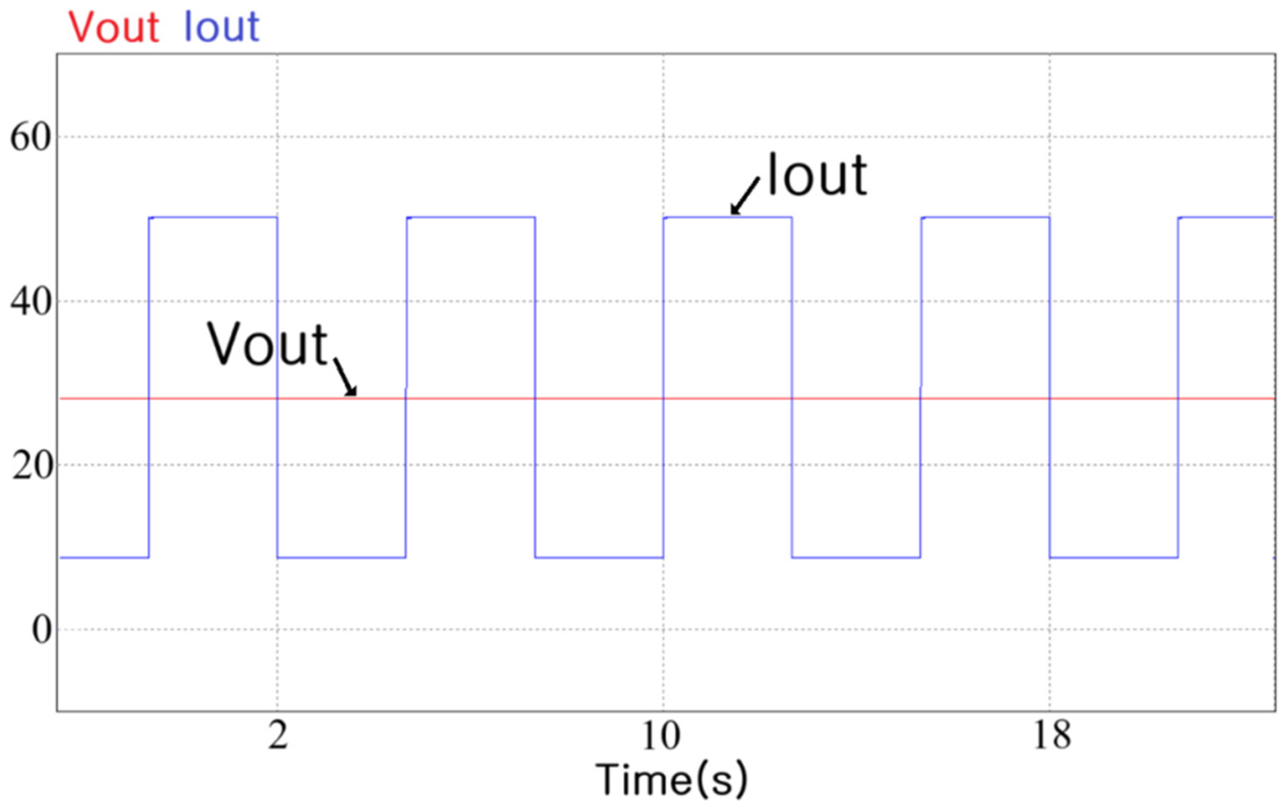
Figure 22 exhibits the PSIM simulation waveforms of the load variable output voltage and output current.
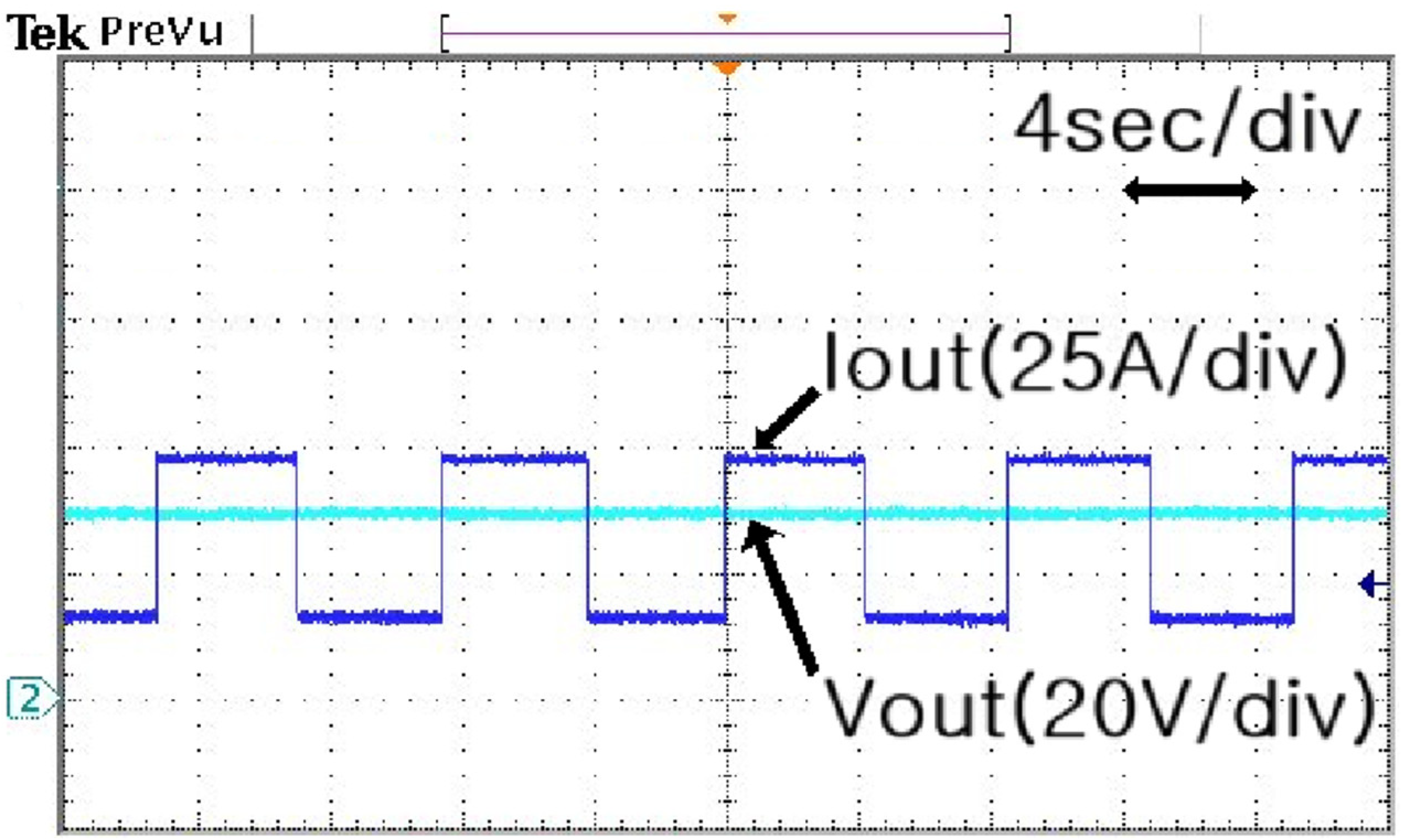
Figure 23 shows the experimental waveforms of the output voltage and output current obtained when the load is changed.
A comparison of the PSIM simulation waveform in
Figure 22 with the experimental waveform in
Figure 23 shows that they are almost identical. In
Figure 23, the output voltage of the LLC resonant half-bridge converter is tested at 28 V and the load current is varied from 15 to 50 A, which experimentally confirms the stable operation of the LLC resonant half-bridge converter with load changes.
For the proposed LLC resonant half-bridge converter for the batteries of personal mobility devices, since a large current of 50 A is output at the maximum output current, no inrush current should be generated during initial startup.
Therefore, in the LLC resonant half-bridge converter, the current needs to be gradually increased through the frequency duty control of the main switch.
When an inrush current is generated during the initial start-up, continuous stress is applied to the lithium-ion battery, which may damage the separator of the lithium-ion battery. Subsequently, the lifespan of the battery could be reduced.
Therefore, rapid chargers based on the proposed LLC resonant half-bridge converter are characterized by a gradual increase in the current with a constant slope during the initial startup without the generation of an inrush current.
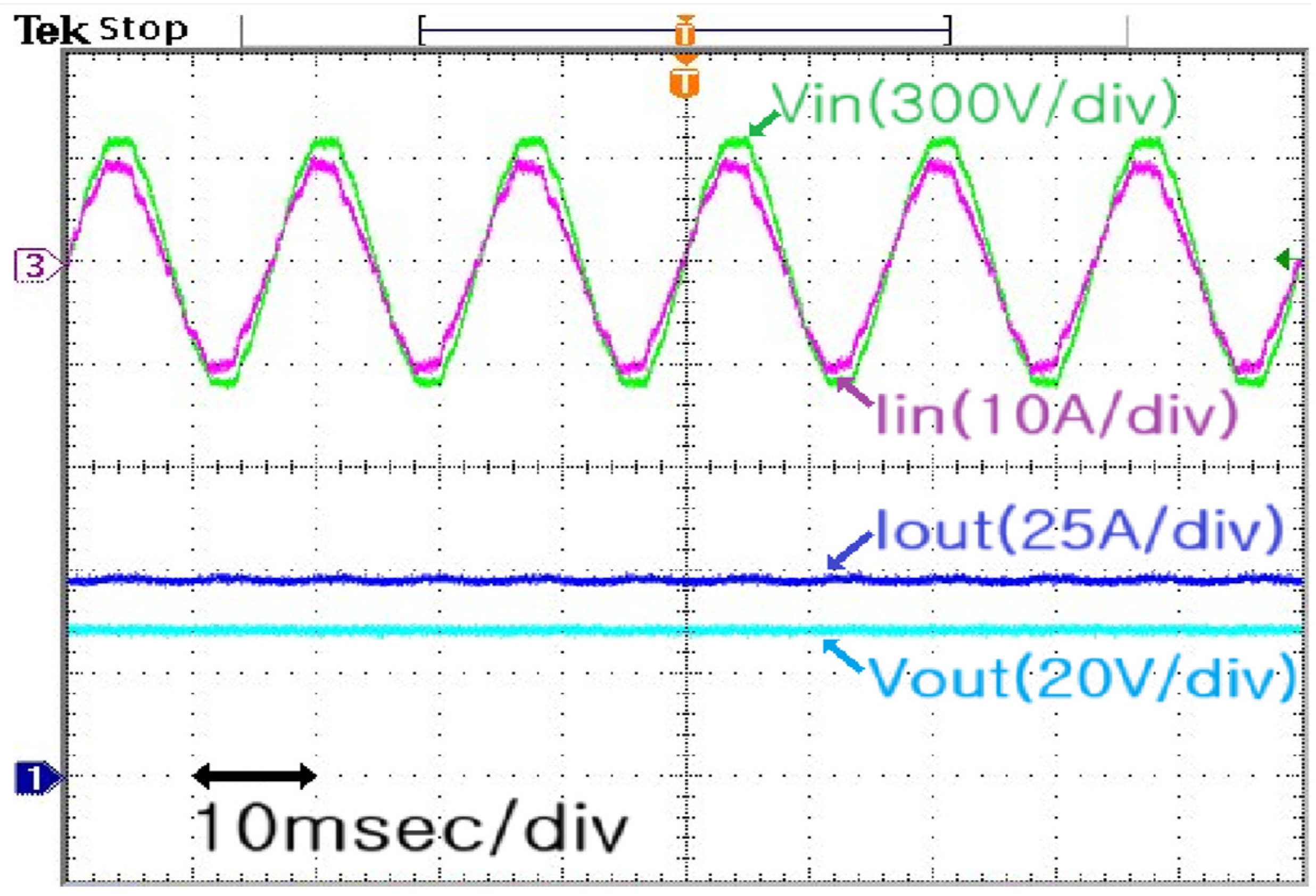
Figure 24 shows the experimental waveforms of the input voltage, input current, output voltage, and output current at full load.
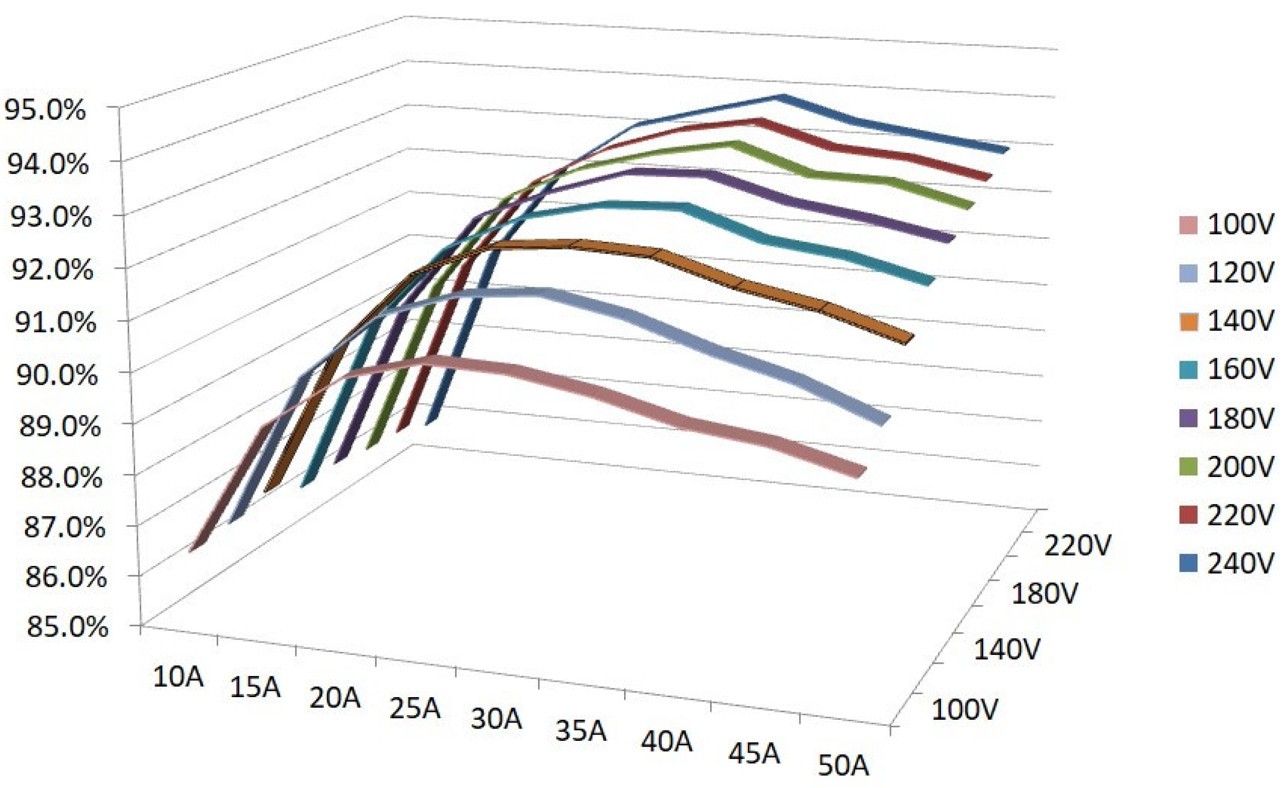
Figure 25 presents the efficiency characteristics according to the input voltage and load current. A charging test is performed for a lithium-ion battery using the rapid charger based on the proposed LLC resonant half-bridge converter.
The results show that the overall efficiency of the battery is about 86–93%.
The input voltage is varied from 100 to 240 V, and the overall efficiency is measured at the output current of up to 50 A. The efficiency increased with the input voltage and load current.
This experiment verifies that the maximum efficiency is 93.564%, and 28 V, 50 A is stably output without an initial inrush current.
Therefore, the simulations and experiments confirm that the rapid charging apparatus based on the proposed LLC resonant half-bridge converter is suitable for charging the batteries of personal mobility devices.
Table 2 compares the proposed charging system to the previous one.
7. Conclusions
This study proposed an LLC resonant half-bridge converter for the rapid chargers of personal mobility devices.
The operation of each mode of the LLC resonant half-bridge converter were analyzed: = , < , and > .
The LLC resonant AHB converter was used in the charging apparatus of personal mobility devices. In terms of battery charging, a full load or heavy load was initially applied and a light load was continuously applied toward the end. The LLC resonant AHB converter method that operates at > , was found to be the most appropriate.
Subsequently, the mathematical modeling of the of the LLC resonant converter operating under > conditions was performed.
The conversion ratio curves of the proposed LLC resonant converter at full and light loads were simulated using the MATLAB program.
Additionally, to validate the proposed method, PSIM was used to simulate and experiment with an LLC resonant AHB converter capable of rapidly charging a 1.5 kW battery.
The proposed charging system detects the normal connection of the battery in real time, starts charging, gradually matches the output voltage of the LLC AHB converter with the battery voltage, and gradually increases the output current of the battery. It smoothly charges Li-ion batteries. If the polarity of the battery is incorrectly connected, the output relay does not operate, thereby improving safety during battery charging. The efficiency of the proposed converter was determined by varying the output voltage of 28 V and the load current from 15 to 50 A. The converter responded stably to the load changes in the experiment, and the maximum efficiency was 93.564%.
The proposed converter is suitable for the rapid charging of micro-electric vehicles and mobility device batteries, and it is expected to have wide application prospects.


