Review

A Review on Cooling Systems for Portable Energy Storage Units

by
Alireza Eslami Majd
1,*,
Fideline Tchuenbou-Magaia
1,
Agnero M. Meless
1,
David S. Adebayo
1 and
Nduka Nnamdi Ekere
2
1
Department of Engineering, School of Engineering, Computing and Mathematical Sciences, University of Wolverhampton, Wolverhampton WV1 1LY, UK
2
Faculty of Engineering and Technology, Liverpool John Moores University, Liverpool L3 2ET, UK
*
Author to whom correspondence should be addressed.
Energies 2023, 16(18), 6525; https://doi.org/10.3390/en16186525
Submission received: 14 July 2023 / Revised: 27 August 2023 / Accepted: 4 September 2023 / Published: 11 September 2023
(This article belongs to the Topic Advanced Heat and Mass Transfer Technologies)

Abstract

:
Achieving the global electricity demand and meeting the United Nations sustainable development target on reliable and sustainable energy supply by 2050 are crucial. Portable energy storage (PES) units, powered by solid-state battery cells, can offer a sustainable and cost-effective solution for regions with limited power-grid access. However, operating in high-dust and high-temperature environments presents challenges that require effective thermal management solutions. This paper is a comprehensive review of thermal management systems for PES units, with a specific focus on addressing the challenge of overheating in airtight designs. The review of various active and passive cooling systems is conducted through extensive study of the relevant literature, which is significant in providing insights into the operation, performance parameters, and design options for different cooling system technologies. The findings from this review show heat pipe (HP) technologies as key cooling-system solutions for airtight PES units. Specifically, loop and oscillating HPs, as well as the vapour chamber, offer desirable features such as compactness, low cost, and high thermal conductivity that make them superior to other alternatives for the cooling systems in PES. The insights and knowledge generated via this review will help facilitate the design and development of innovative, efficient, and reliable PES units, thereby contributing to the advancement of off-grid renewable energy applications and enabling sustainable power solutions worldwide. Furthermore, an appropriate design of PES units can help in reducing capital and maintenance costs.

1. Introduction

The proliferation of electrical and electronic devices has created an urgent need for advanced energy supply technologies, particularly in regions lacking access to utility energy networks. Conventional methods of providing electricity, such as portable fossil fuel engines, pose significant challenges including CO2 emissions, noise pollution, limited fuel availability, and high costs [1]. To address these issues, there has been a growing focus on portable energy storage (PES) units that employ various storage technologies [2]. These units have the capability to be charged using renewable energy sources, such as solar photovoltaic (PV) systems, thereby, offering clean, affordable, and efficient means of electricity supply. PES units are particularly vital in areas where access to power grid networks is limited or non-existent. The utilisation of PES units as affordable energy systems provides a sustainable solution for regions facing inadequate energy supply and promotes equitable access to electricity.

1.1. PES Unit

The development of PES units has witnessed significant progress in the market in recent times. With the growing demand for portable electronic devices and supplying energy as off-grid systems, researchers and manufacturers have focused on advancing the design and performance of PES units. The ongoing design advancements and innovations in PES units have greatly contributed to the development of reliable and efficient power solutions. This includes numerous designs, exploring efficient energy storage technologies such as solid-state batteries, that aim to improve energy density, compactness, safety, durability, and enhancement of overall portability.
A PES unit typically comprises a storage system and an inverter for energy conversion. It also includes vital subcomponents: a cooling system to remove heat, electric control boards for managing the electricity flow, and power input/output ports for device connections. These components ensure efficient energy storage, conversion, and system control within the PES unit. Figure 1 shows a 1 kW power capacity PES unit.

1.2. Storage System

PES units commonly utilise rechargeable storage systems, including supercapacitors, lead-acid batteries, and solid-state batteries, such as lithium-ion batteries (LIBs) and sodium-ion batteries (SIBs). Among these options, LIBs are widely preferred because of their high energy density and extended run times compared to other alternatives. While hybrid semiconductors can achieve energy densities of up to 100 Wh/kg, the solid-state battery cells, particularly LIBs, offer nearly three times more energy storage capacity than supercapacitors [4]. Although SIBs are considered environmentally friendly and benefit from the abundance of sodium, their current energy density is lower than that of LIBs, and they are still mainly in the developmental phase [5,6].
The adoption of solid-state battery cells, particularly LIBs, has witnessed significant growth recently across various electronic packages. However, the battery mechanism involved in converting chemical energy into electrical energy generates heat, leading to an overall temperature increase and thermal runaway [7,8]. This exhibits specific challenges in high-power systems like PESs during high-current and high-voltage charging/discharging operations.
The optimal operating temperature range for LIBs is typically between 25 °C and 50 °C [9]. Overheating in LIBs results in the deposition of metal lithium ions at the anodes, leading to reduced battery lifespan, performance, and depth of discharge [10]. Elevated temperatures also contribute to the formation of inorganic species near the cathodes, which diminishes lithium intercalation capacity and overall battery performance [11]. Additionally, increased temperatures within battery cells elevate the risk of lithium-ion deposition, accelerating battery degradation and increasing the likelihood of internal short circuits [12,13,14]. Mechanical stress-induced cracks at the anodes further pose a significant challenge, reducing performance and compromising the reliability and integrity of LIBs operating under high-temperature cycling conditions [15,16].

1.3. Power Inverter

The power inverter plays a crucial role in PES units by converting direct current (DC) power from storage units into alternating current (AC) power, enabling the operation of various electronic devices and appliances. However, the effective management of heat flux, caused by power waste during the electricity conversion process in metal-oxide semiconductor field-effect transistors (MOSFETs), presents a significant challenge in DC-to-AC inverters, especially as the junction temperature is recommended to be under 125 °C [17,18]. This conversion process generates a considerable amount of heat, which can have a detrimental impact on the inverter’s performance and the reliability of the PES unit. For example, a typical DC-to-AC inverter exhibits an average of 10% power lost, which means a PES unit using a 1 kW inverter would experience 100 W of power lost. In a common PES unit with a 2 kWh LIB pack weighing 11 kg, the battery pack constitutes approximately 80% of the unit’s total mass. With a specific heat capacity of 0.29 Wh/(kg °C) for the LIBs [19], the battery pack experiences a heat flux of 80 Wh after one hour of operation. This results in an additional temperature increase of 28 °C for the battery.
Figure 2 shows the physical view and temperature distribution (with average temperature of 52.9 °C) for a typical 1 kW DC-to-AC inverter used in a 2 kWh PES unit and operating at room temperature (22 °C) for an hour.

1.4. PES Design Challenge

As the demand for lightweight and portable PES units increases, manufacturers are now focusing on reducing the size of the package. This scaling-down process emphasises the significance of improving subcomponent design to achieve optimal outcomes. Similar to other large electric packages, the successful miniaturisation of PES units relies on the enhancement of subcomponent design to ensure efficient and reliable operation and performance [20,21,22,23,24,25,26,27,28,29]. The compact arrangement of electronic subcomponents leads to a higher concentration of power-loss density in the form of heat, resulting in increased internal temperatures within the package. Consequently, this significantly exposes the electronic components to thermo-mechanical stresses [30,31]. Such conditions can adversely affect the performance and stability of the subcomponents, while greatly reducing the system reliability and safety [32,33,34]. In particular, the operation of electronic devices with battery cells at high temperatures demands considerable attention because of the associated hazards, including the potential for battery-cell failures that can halt the entire package operation and pose serious dangers, like an explosion [35,36,37].
Hence, there is an indispensable need for an effective thermal management system to cool down the package, particularly, during high-temperature operations [38,39,40]. This need is even more crucial when electronic packages incorporate battery packs, as their performance is highly sensitive in harsh operational conditions, such as high charging/discharging rates or when operating in hot tropical environments. The challenge becomes more significant when a large heat-generating component, such as a power inverter with high power output, is integrated with the battery packs inside a PES unit. This means that not only do the batteries generate heat, but the inverter also produces additional heat. Moreover, the challenge becomes even more crucial when the design of the PES unit requires it to be airtight and have high performance, rendering traditional cooling systems like fans and vents ineffective. In such cases, alternative cooling methods need to be employed to ensure efficient heat dissipation and prevent thermal issues.
This paper presents a comprehensive review of thermal management systems for PES units, with a specific focus on addressing the challenge of overheating in airtight designs. This paper goes beyond addressing the challenge of overheating in airtight designs as it also emphasises the potential scalability and adaptability of the presented cooling solutions for power and energy system (PES) units of varying sizes, power outputs, and storage capacities available in the market. Notably, the implementation of passive cooling strategies not only enhances the energy efficiency of the system but also effectively mitigates heat within the unit. This approach concurrently reduces the potential ingress of air and dust particles, thereby enhancing the reliability and durability of the PES unit in diverse regions. Collectively, these advancements contribute to improved cost effectiveness, underscoring the utility of this paper as a resource for designing adaptable thermal management solutions for a wide range of PES unit applications.
The paper is structured as follows: first, an overview of PES units and their main components is provided in Section 1, highlighting the significance of efficient thermal management for optimal performance. In Section 2, thorough examinations of various cooling systems, including active liquid, thermoelectric, and heatsink, are presented. Various types of heat pipes (HPs) used for cooling systems and their limitations are discussed in Section 3, followed by the conclusion in Section 4. Finally, future works and challenges are discussed in Section 5.

2. Cooling Systems

Cooling systems for electronic packages can be broadly categorised into active and passive cooling systems, or a combination of both. Figure 3 provides an overview of the main classifications of active and passive thermal management systems commonly used for cooling PES units. Passive cooling systems, which rely on natural convection, conduction, and radiation, offer a practical solution for managing heat in electronic packages without the need for power consumption [41]. In contrast, traditional cooling techniques involving active cooling systems with fans and vents for forced convection present challenges in terms of miniaturisation, airtightness, power efficiency, and cost effectiveness, particularly in compact and high-power designs of PES units and electronic packages [42,43,44].
Conventional active cooling systems, such as radiators and fans, are commonly used for heat dissipation in high-power electronic packages. However, they are associated with operational issues, including the requirement for relatively large system volume and high power consumption.
Furthermore, these systems may suffer from coolant leakage and evaporation problems in the case of forced liquid cooling [41]. Radial fans, the prevalent active cooling approach, also have drawbacks, such as noise, low efficiency, limited airtightness, and a shorter lifetime compared to other components of the package [45]. To address some of these challenges, the utilisation of piezoelectric fans has been explored as an alternative cooling method [46].
Advanced active cooling systems, such as active liquids, are another prominent sub-class of active cooling systems. These systems provide superior cooling performance compared to traditional cooling methods. However, they often face reliability challenges because of the limited lifespans of the necessary subcomponents involved in their operation [47,48,49]. The use of active liquids introduces additional complexity and maintenance requirements, which can impact the overall reliability and longevity of the cooling system [39]. Despite their enhanced cooling capabilities, careful consideration must be given to the trade-offs between performance and reliability when implementing active liquid cooling systems in PES units and electronic packages.
Passive cooling systems, on the other hand, offer distinct advantages as practical solutions for cooling electronic packages operating under high-temperature conditions. By transferring heat to an external ambient medium through natural convection, conduction, and radiation, passive cooling systems provide simple implementation, high reliability, and low manufacturing costs [50]. Examples of passive cooling systems include combinations of heatsinks and HPs, which leverage phase change recirculation to enhance heat transfer and effectively remove heat while minimising power consumption and overcoming the limitations associated with active cooling techniques.

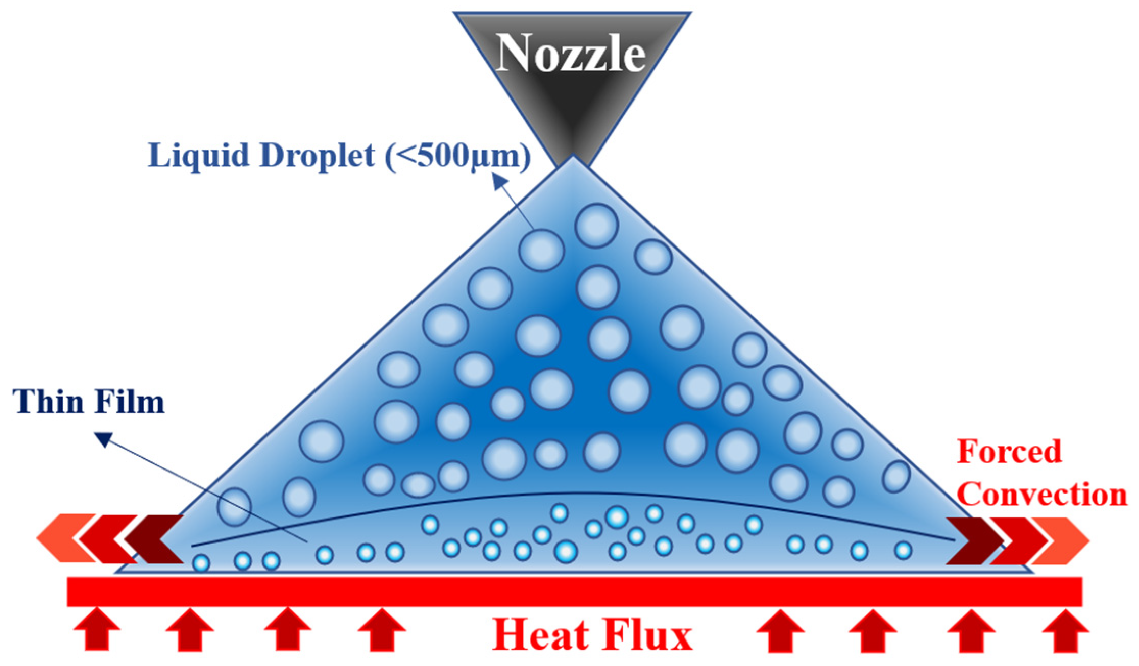
2.1. Active Liquid Cooling

Thermo-hydrodynamic cooling systems, also known as active liquid cooling systems, represent an advanced approach for cooling electronic packages. These systems utilise coolant liquids, such as water, glycol, and ethylene, to create a high heat-transfer convection capacity within a coolant layer. As shown in Figure 3, various active liquid technologies have been developed, including liquid spray [51,52], jet impingement array [53,54], synthetic jet [55], and microchannels array [56].
The liquid spray cooling system operates by propelling liquid through a spray nozzle, which impinges on the heat surface at high velocities, forming a thin cooling film for heat dissipation, as depicted in Figure 4. To enhance the thermal performance of the liquid spray cooling system, multiple micro-nozzles can be utilised in a jet impingement array configuration. This arrangement increases the liquid flow pressure and the flow rate, promoting forced convection heat transfer between the fluid cooling film and the heat surface. Furthermore, the integration of a vibrating diaphragm in the jet impingement cooling system creates a more turbulent fluid flow, resulting in a higher heat transfer capacity. This technique, known as synthetic jet, involves periodic injection and suction of the coolant liquid through the nozzle outlet, intensifying the interaction between the fluid and the heat surface [54].
Microchannel cooling systems, categorised under “Pumped Fluid Loops”, is another active liquid approach in which the coolant liquid is directed through parallel micro-diameter channels within a heatsink. The heat is transferred from the hot side to the cold side through these channels. However, the laminar and low flow rate nature of the coolant liquid in microchannels results in limited heat transfer capacity. To enhance its efficiency, a microchannel cooling system can be combined with jet impingement technologies to increase the liquid flow rate and induce turbulence, thereby optimising its heat transfer capability [57,58,59].
While active liquid cooling systems effectively remove heat from electronic packages, they do possess certain weaknesses. These systems can be complex in design, resulting in increased costs. Moreover, there is a risk of liquid leakage, particularly in miniaturised and compact package designs. Therefore, careful consideration must be given to the trade-offs between cooling performance, system complexity, cost, and the potential risks when implementing active liquid cooling systems for electronic packages.

2.2. Thermoelectric Cooling System

Thermoelectric cooling (TEC) has emerged as a promising cooling technique for electronic packages. Figure 5 provides a schematic view of the thermoelectric cooling system using a heatsink for a higher thermal performance.
The operation of TEC is based on the Peltier effect, where a DC flows through a series of circuits consisting of P-type and N-type semiconductor layers that are thermally connected in parallel. The thermoelectric mechanism involves the movement of electrons from the N-type to the P-type layers, facilitating heat transfer between the heat-absorbing side and the heat-dissipating side. When cooling a package operating at a lower temperature than the ambient, the TEC requires an external power supply to actively remove heat (referred to as active cooling in TEC). Conversely, when the TEC operates in reverse and the inside of the system (heat-absorbing side) is at a higher temperature than the outside (heat-dissipating side), the thermoelectric device generates a voltage based on the temperature gradient. This TEC mechanism, which generates electricity, is known as a thermoelectric generator (TEG), and the corresponding cooling system that utilises the generated power is called a thermoelectric self-cooling (TSC) system [60]. TSC systems generally exhibit higher efficiency and performance compared to conventional TEC systems because of their self-powering mechanism. They can be categorised as passive cooling systems when the design can balance the generated power with the required power.
While TEC systems offer unique advantages in terms of miniaturisation, flexibility, and noiseless operation, their limited cooling capacity, high power consumption, reliability at high temperatures, and heat dissipation challenges are some of the important considerations when implementing them as cooling methods for electronic packages. These cooling systems face challenges at high temperatures and require a high-power DC supply when there is a significant temperature difference between the cooling area and the ambient environment [60,61,62,63]. Additionally, TEC systems may experience reliability issues at high temperatures. The thermoelectric modules can degrade over time because of factors such as thermal cycling, mechanical stress, and material degradation. This can impact the long-term performance and reliability of the cooling system. Furthermore, TEC systems are sensitive to heat dissipation, often requiring the use of additional cooling components such as heatsinks or fans, which can add complexity and increase the overall size and cost of the cooling system [62].
TEC systems, despite their advantages, may not be the optimal choice for compact, effective, and reliable cooling in harsh environments for PES units. Their limitations, such as limited cooling capacity, high power consumption, reliability issues at high temperatures, and sensitivity to heat dissipation, pose significant challenges.

2.3. Heatsinks

The use of heatsinks is a common and effective approach for thermal management in electronic packages, including PES units, by efficiently absorbing and dissipating heat. They can be seamlessly integrated into cooling systems that require high heat dissipation rates to the ambient environment [64]. Typically, heatsinks consist of a bulk structure with multiple extended surface fins in contact with a heat spreader, which is connected to the hot surface. The design of the fins aims to enhance the air convection interface area, facilitating maximum heat transfer to the ambient environment. Heat transfer in a heatsink-based cooling system involves three stages, namely, (i) thermal conduction from the hot surface to the heat spreader, (ii) thermal conduction from the heat spreader to the heatsink, and (iii) heat dissipation from the heatsink to the ambient environment primarily through forced or natural air convection, along with slight radiation. Therefore, the heat transfer capacity of heatsinks relies on factors such as the thermal conductivity of the materials used, the design and configuration of the bulk structure and fins impacting convection and radiation, as well as the structural characteristics, like height, thickness, fin numbers and intervals, and the breadth of the bulk structure. Figure 6 provides a schematic view of the heatsink structure and its thermal operation.
Copper and aluminium alloys are commonly chosen materials for heatsinks in electronic packages because of their favourable attributes, such as high thermal conductivity, ease of manufacturing, corrosion resistance, and cost-effectiveness [65]. Additionally, aluminium holds the advantage of being lightweight, making it suitable for applications where a lighter structure is desired, such as PES units. However, a key challenge in heatsink fabrication lies in achieving a seamless and uniform thermal contact between the heatsink and the heat spreader, minimising any air gaps or surface irregularities [66,67]. These air gaps hinder efficient heat transfer as noncontact conduction through air has a low thermal conductivity (~0.026 W/mK at room temperature) [68,69,70]. To address this challenge, thermal interface materials (TIMs) are commonly used to fill and minimise the gaps, ensuring improved thermal conduction [71]. TIMs can take the form of soft materials such as greases, gels, phase change materials, adhesives, and liquid-metal-based solutions, as well as hard materials, including solder, graphene, silicon, tapes, and composite pads. TIMs not only facilitate heat transfer but can also provide effective electrical insulation or establish strong mechanical connections, particularly when employing hard TIMs, as required in specific applications [72].

3. Heat Pipe

Heat pipes (HPs) are highly efficient passive cooling systems used in various electronic packages, ranging from smartphones and laptops to portable energy storage units and electric vehicles. These closed systems consist of sealed metal tubes, typically made of copper, titanium, or aluminium, filled with a working fluid, such as water, acetone, methanol, or ethanol. As part of a thermodynamic cycle, the working fluid in HPs receives heat from the heat source, vaporises, flows to the condenser section, condenses, and finally returns to the evaporator section. This continuous cycle allows for effective heat transfer from the heat source to the ambient environment without requiring any additional power consumption [73]. Water is commonly used as the working fluid in HPs because of its nontoxicity, wide operating temperature range (up to over 200 °C), and high thermal conductivity. However, other liquids may be employed depending on specific application requirements [65,74]. The choice of the working fluid and its characteristics, such as low density, high thermal conductivity, and appropriate phase transition temperature, play a crucial role in enhancing the cooling performance of HPs.

3.1. Thermosyphon Heat Pipe

Thermosyphon heat pipes (TPHPs), also known as two-phase closed thermosyphons (TPCTs), are a type of HP system that operates based on natural convection and gravitational force. They normally use a fully sealed tube to circulate the working liquid from the condenser to the evaporator. In TPCTs, the heating side is positioned at a lower level than the cooling side, utilising the upward flow of the liquid driven by gravity [75]. The structure and functioning of TPCTs are depicted in Figure 7. However, implementing TPCTs in compact electronic packages presents challenges, as the design arrangement requires the condenser to be located at the top of the system. Additionally, bends in the tubing can negatively impact TPCT performance by reducing flow oscillations and potentially leading to dry-out in the evaporator section [76].
Water, ammonia, and methanol are commonly used as coolant liquids in TPCTs. Furthermore, thermally conductive liquids containing nanoparticles, such as carbon nanotubes (CNTs), can be employed to enhance thermal characteristics and overall heat removal performance. Studies have demonstrated that denoised water with 2% CNTs exhibits optimal improvement in TPCT thermal performance, as it enhances the boiling heat transfer coefficient and critical heat flux in the evaporation section [77].

3.2. Conventional Heat Pipe

In conventional heat pipes (CHPs), where gravitational force alone is not sufficient to circulate the condensed liquid back to the evaporator, a wick structure is incorporated inside the tube. This wick structure, typically in the form of grooves, increases the interface surface area between the liquid and the tube surface, thereby enhancing the heat transfer capacity [78]. The presence of the wick creates a capillary pressure, which facilitates the return of the condensate (liquid) to the evaporator while allowing the vapour to flow towards the condenser [79]. Figure 7 provides a comparison of the thermodynamics and operational mechanisms between TPCTs and CHPs with a wick structure.
CHPs are highly suitable for cooling battery packs because of their compact size, lightweight nature, ability to be produced in various shapes and sizes, and high heat removal capacity [42]. For instance, a CHP implementation in an LIB module consisting of eight prismatic cells was able to effectively dissipate 400 W of heat from the module while maintaining the temperature of the battery cells below 55 °C [43].
Figure 8 illustrates the characteristic profiles of liquid, vapor, and capillary pressures along an HP with a wick structure. At the condenser section, the vapour and liquid pressures are nearly balanced, resulting in a close-to-zero capillary pressure. Moving along the HP towards the evaporator, the vapour pressure increases because of heat absorption and vaporisation of the working fluid. However, the liquid pressure experiences a significant drop at the evaporator because of frictional losses incurred while flowing through the wick structure. Consequently, the evaporator region exhibits the highest capillary pressure, which facilitates the circulation of the fluid within the HP.
To ensure sufficient condensate return within the HP and avoid dry-out of the wick, the capillary pressure difference ( P c p ) along the HP must be greater than the total pressure drops experienced in the pipe [80]. This relationship is expressed in Equation (1).
P c p P L + P V + P g + P p h  
where P L and P V represent the frictional pressure drops along the liquid and vapour paths, respectively. P b is the pressure drop in liquid caused by gravity and body force, which can be positive or negative depending on the pipe orientation. P p h accounts for the pressure drop caused by phase transition, although it is typically negligible except in cases of liquid metal HPs with extremely high evaporation rates [81].
From Equation (2), P c p can be calculated using the capillary pressure drop at the evaporator ( P e ) and the condenser ( P c ) . Similarly, P e and P c   can be calculated using Equation (3).
P c p = P e P c
P = 2 σ R = 2 σ r e f f c o s θ
In Equation (3), σ represents the surface tension of the liquid, θ is the wick-fluid contact angle that indicates the wettability of the wick, R is the pore radius, and r e f f is the effective pore radius of the wick. The contact angle θ indicates the wettability of the wick structure, with θ approaching zero indicating a fully flooded condenser where the wick structure absorbs the maximum amount of liquid. In this scenario, as suggested by Equation (3) and Figure 8, P c   is nearly zero, and the P c p is equal to P e . Figure 9 illustrates the wick parameters and the liquid–vapor profile along the HP. Furthermore, Equation (3) indicates that a smaller pore radius and a higher liquid surface tension result in a higher capillary pressure.

3.2.1. Micro Heat Pipes

Micro heat pipes (MHPs) are miniature versions of HPs, characterised by their small hydraulic diameter (less than 0.5 mm) and being several centimetres in length. They can be easily integrated with heatsinks and heat spreaders to enhance the thermal performance of cooling systems, offering up to three times higher efficiency compared to other HPs [82,83,84]. While MHPs have gained significant attention for cooling compact and miniaturised electronic packages like CPUs [85], they may not be the ideal choice for larger packages such as power electronic systems because of factors like manufacturing cost and lower structural strength. MHPs are primarily suited for local heat removal and can only transfer heat in the axial direction. To overcome this limitation, MHPs can be integrated with heat spreaders to distribute heat more effectively [86].
Due to their small pipe diameter, MHPs cannot incorporate a traditional wick structure to enhance capillary pressure. However, they often feature sharp-edged pipe cross-sections that serve as a pseudo-wick to assist in capillary action [87]. Figure 10 provides a schematic view of an MHP with three different cross-sectional shapes with differences in the edges and corners affecting the flow vapour regime inside of the MHP.

3.2.2. Heat Pipe Limitations

There are several thermodynamic limitations that can impact the optimal performance of HPs. These limitations include sonic, viscous, capillary, entrainment, and boiling limits [88]. Figure 11 shows the various limits for a water-wick HP design. Sonic and viscous limits typically occur at very low temperatures and have minimal impact on HP performance in cooling large electronic packages like PES [89,90]. The remaining three limiting factors are discussed in the next subsections. Understanding and mitigating these limitations are crucial for optimising the performance of HPs in various applications, including cooling systems for large electronic packages like PESs.

Capillary Limit

The concept of the capillary limit revolves around the maximum feasible fluid circulation within a capillary structure. In this context, a capillary structure has the capacity to sustain the movement of a designated working fluid up to a specific threshold. Beyond this threshold, however, the capillary pressure loses its efficacy in overcoming the cumulative pressure drop experienced within HPs. Consequently, this scenario can lead to the depletion of liquid return in the evaporator, resulting in dry-out [88]. As previously discussed in Section 3.2, strategies such as employing a working fluid with higher surface tension and utilising HPs with specific wick structures are primary approaches to enhance the capillary limit [91].
The effectiveness of capillary action within the wick structure is significantly impacted by the wick’s permeability. A higher permeability is associated with a lower liquid pressure drop across the wick and a more efficient rate of liquid return. However, achieving higher permeability often involves trade-offs, as it typically requires a larger pore radius within the wick, which can conflict with the goal of increasing capillary pressure that often demands a smaller radius [92]. This interplay between conflicting parameters poses a significant challenge to optimise the wick structure configuration for each HP design. For example, it has been reported that for HPs with small lengths (<20 cm), utilising a relatively small pore radius can be more advantageous compared to HPs with larger pore radii [88].
The permeability of the wick is also influenced by the geometric shape and structure of the wick itself. Figure 12 illustrates the cross-sections of various wick types used in HPs, including wrapped screen, sintered metal, axial groove, open and integral artery, open annulus, and crescent screen wicks. Among these wicks, the integral artery wick exhibits characteristics such as high permeability, thermal conductivity, and small pore radius, all of which contribute to achieving very high capillary pressure. Wrapped screen and sintered metal wicks typically have small pore radii, which enable them to provide high capillary pressure. However, they often have low permeability, which can partially affect the capillary pressure. Additionally, sintered metal wicks can be challenging to manufacture because of their small pore radius. Other types of wicks, such as groove wicks, generally possess sufficiently high thermal conductivity and permeability, but they tend to have relatively low capillary pressure because of their larger pore radius [93].
The thermal performance of HPs is also significantly influenced by various geometry parameters, including orientation and tube bending, which can have a substantial impact on the performance of the wick structure. The HP’s orientation impacts wick selection for optimal performance. When an HP is oriented upwards, with the evaporator below and the condenser above, it enhances capillary pressure. This is especially beneficial for low-capillary-limit HPs and particularly for HPs with shorter lengths. Vertical positioning has been found to decrease the thermal resistance of a groove-wick HP with a length of 200 mm by up to 65% [88].
Tube bending also influences the capillary action and fluid transport properties in HPs. While bending is often used to save space in HP cooling systems, it can detrimentally affect the heat transfer capacity. Bending reduces the wick’s porosity in the bent area, hindering fluid flow. Moreover, the change in flow regime caused by bending leads to a higher fluid thermal resistance. Even a small bend radius can significantly decrease the heat transfer capacity. For example, it is reported that a U-shaped HP with a 10 mm bend radius and a 3 mm thickness experiences up to 10% reduction in heat transfer capacity compared to a straight HP [94].

Entrainment Limit

Due to the opposing directions of liquid and vapour flow in HPs, shear forces are generated at the liquid–vapor interface. As the vapour flow increases, these interfacial shear forces may exceed the surface tension of the liquid [95,96]. Consequently, liquid droplets can be entrained with the vapour flow, leading to a dry-out of the evaporator section as no more liquid is returning to it. This phenomenon is known as the entrainment limit and can be quantified using the dimensionless Weber number, as given by Equation (4) [81].
W e = 2 ρ v v 2 r v σ
where ρ v represents vapour density, v denotes vapour velocity, r v is the core vapour radius, and σ is the fluid surface tension. The Weber number compares the interfacial force with the surface tension force. A lower Weber number indicates a lower interfacial force (shear force) and reduced likelihood of entrainment. To avoid the entrainment limit and achieve the heat transfer capacity during HP operation, the Weber number must be kept below unity.
Addressing the entrainment limit can be achieved through two different approaches. First, the use of composite wicks, which consist of two different pore radii and wick structures, such as a combination of groove wicks (as large pores) and sintered wicks (as small pores). While manufacturing such composite wicks can be challenging, this structure allows vapour and liquid to flow through separate channels, effectively reducing the interfacial shear forces responsible for entrainment. Additionally, the composite wick enables the HP to achieve higher permeability and capillary pressure, thus increasing the heat transfer capacity. The second approach involves the implementation of a loop heat pipe (LHP) system, which is further discussed in Section 3.3.

Boiling Limit

The boiling limit in HPs is associated with the maximum radial heat flux that induces the formation of bubbles within the wick structure. When the heat flux is high enough, it causes the working fluid to boil, resulting in the nucleation of bubbles that become trapped in the wick structure. The presence of these bubbles obstructs the return of liquid, leading to evaporator dry-out. Therefore, the design of the wick structure is crucial in mitigating boiling, and an HP with a high effective thermal conductivity of the liquid-wick combination can effectively reduce the probability of boiling occurring.
Furthermore, the choice of working fluid in HPs can influence the boiling limit. Using a working fluid with a high critical superheat temperature, such as in liquid-metal HPs, can help inhibit bubble formation. Liquid-metal HPs rarely experience boiling limits because of their small nucleation radius [88].
Another approach to addressing the boiling limit is the implementation of oscillating heat pipes (OHPs), which allow the co-existence of both vapour and liquid phases within the HP tube. OHPs can help mitigate the challenges associated with the boiling limit by enhancing the fluid circulation and preventing the formation of stagnation regions. Further details on the operation of OHP systems are discussed in Section 3.4.

3.3. Loop Heat Pipe

A loop heat pipe (LHP) consists of four essential components: (i) the evaporator (containing the primary wick), (ii) a compensation chamber, (iii) a condenser, and (iv) liquid and vapour lines. Unlike CHPs, LHPs provide the added advantage of integrating a secondary wick with different pore radii, as depicted in Figure 13. This configuration allows for the coexistence of a low capillary radius and high permeability within the wick structure. Additionally, the separation of liquid and vapour flows into distinct channels within the LHP eliminates the potential occurrence of an entrainment limit during operation.
Various liquids can be used in LHPs, including water, acetone alcohols, tetrafluoroethene, and R134a (for high-temperature applications) as well as propylene and ammonia (for low-temperature applications) [97].
The operation of LHPs involves the absorption of heat at the evaporator, where the primary wick (with a small pore radius) facilitates the high capillary pressure necessary to prevent the return of vapour. The vapour then travels through the vapour line to the condenser, where it undergoes a phase change back to liquid. The resulting liquid flows through the liquid line to the compensation chamber and is subsequently delivered to the evaporator via the secondary wick (with a large pore radius) [98].
Similar to the CHPs, the LHP performance significantly relies on the design requirements, such as the configurations of the condenser and the evaporator (shape, size, and material), the vapour line diameter and bends, pore diameter, wick thickness, fill charge ratio, and the characteristics of the coolant liquid [97,99]. For instance, the experimental study of the heat transfer of a miniature LHP with a disk-shaped evaporator and with water as the working fluid showed that using a biparous copper wick structure has over four times more evaporator heat transfer coefficient (83 kW/m2 K) compared to using mono-porous wicks. It is also determined that the LHPs made of copper perform nearly 30% better than LHPs made of nickel [100]. Putra et al. [42] also experimentally studied the thermal performance of LHPs with evaporators consisting of stainless-steel screen mesh wicks for cooling ordinary LIBs with a 400 W heat flux at standard test conditions. Their investigations showed that using acetone can keep the battery temperature under 50 °C when the heat flux was 1.61 W/cm2. This results in approximately 15% temperature reduction when compared to other investigated liquids such as distilled water and alcohol.
While LHPs represent a significant advancement in mitigating entrainment challenges compared to CHPs, they are not without their inherent limitations. Much like their HP counterparts, LHPs are subject to thermodynamic constraints encompassing capillary, viscous, sonic, and boiling limits [98]. Adding to these challenges, another critical limitation affecting LHPs’ heat transfer capacity is heat leakage [101]. This issue predominates under low charging-pressure conditions, while the capillary limit takes precedence under higher charging pressures [102]. Heat leakage typically occurs through the evaporator sidewalls and the wick, transferring heat from the evaporator to the compensation chamber [103]. This phenomenon can lead to temperature oscillations and increased operating temperatures, which can increase the risk of system failure [104]. Moreover, LHPs are not immune to the challenge of heat transfer distance. This factor can result in an uneven thermal distribution along the HPs, potentially limiting their effectiveness in transferring heat across extended distances [105].

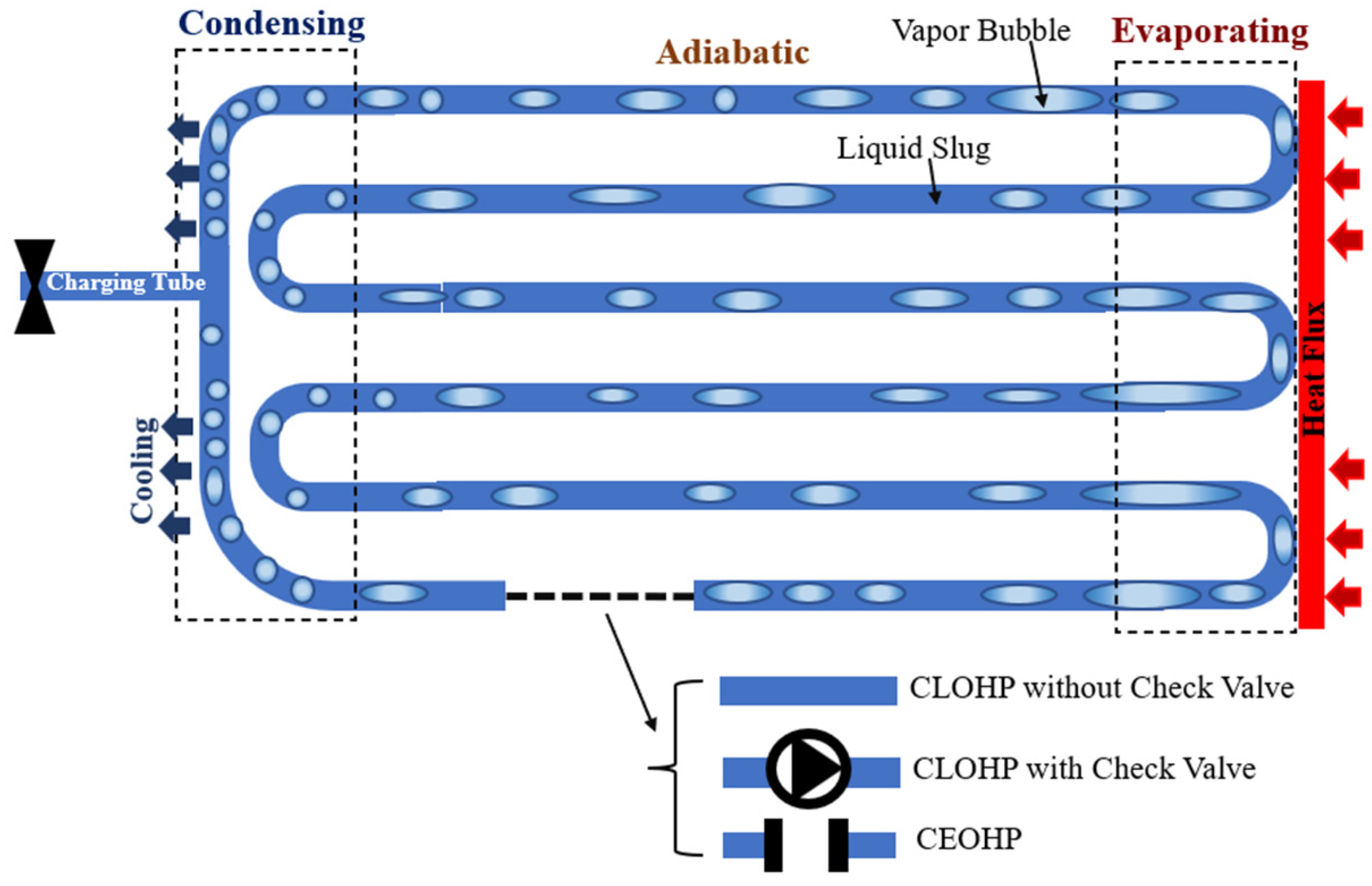
3.4. Oscillating Heat Pipe

Oscillating heat pipes (OHPs) are highly effective heat pipes for heat removal in high-power electronic packages such as PES units. They offer a solution to the boiling limit challenge and possess several advantages, including low manufacturing costs, rapid thermal response, high heat transfer performance, absence of a wick structure inside the tube, and operational flexibility in terms of evaporator and condenser positioning [74,106].
The mechanism of OHPs is based on the continuous movement of bubbles inside a long capillary tube with a small diameter, traveling from the heated section to the cooled section. When a part of the working fluid is exposed to the heat source, it evaporates and generates vapour bubbles because of the increased temperature. The two-phase fluid with higher pressure oscillates and propels the vapour bubbles and liquid slugs from the evaporator towards the condenser [75]. In the condenser, typically a heatsink surrounded by the ambient environment, the moving bubbles lose heat, resulting in additional fluid pressure that facilitates the return flow of the cooled fluid to the evaporator.
OHPs can be designed as closed-loop (CLOHP) systems, with or without a check valve, or as closed-end (CEOHP) systems. In CEOHP systems, which have two closed ends along the capillary tube, the oscillation of bubbles and pressure fluctuations alone contribute to the heat transfer. In CLOHP systems, the bulk fluid can also partially transfer heat as shown in the schematic view in Figure 14. To effectively control the heat transfer direction, a check valve can be used in CLOHP systems to limit the flow of fluid in a specific direction. Furthermore, experiments conducted by Rao et al. [107] demonstrated that horizontal positioning of OHPs can be more effective in heat removal compared to vertical orientations.
Despite OHPs’ numerous advantages, they face specific constraints that influence their performance, just as LHPs. One significant challenge in OHP design lies within their operational limits, primarily influenced by working temperature, input heat flux, and the thermal resistance between the condenser/evaporator sections and the working fluid [108,109,110]. The startup limit is encountered when insufficient input heat flux prevents the initiation of the necessary boiling and pressure differential for bubble movement within the OHP [111]. Conversely, exceeding the maximum allowable input heat flux can lead to excessive bubble movement with insufficient amplitude, resulting in decreased heat transfer capacity [108]. This constraint, which is known as the swept length limit, can result in evaporation rates surpassing the film flow rate towards the evaporator, potentially causing dry-out [112].
The working fluid also introduces limitations, as the viscous limit manifests when the viscous drag of the liquid slug hampers sufficient flow to transfer input power, particularly at lower temperatures [108]. Furthermore, the sonic limit, occurring when vapour velocity equals the local speed of sound, can induce choked flow conditions, negatively affecting OHP performance [113].
Among OHP limitations, significant attention is drawn to the risk of evaporator dry-out caused by insufficient oscillatory flow amplitude and the inability of liquid plugs to return to the evaporator [109,113,114]. Factors such as flow characteristics, filling ratio, tube internal diameters, and orientation contribute to this evaporator dry-out challenge.
The internal tube diameter also plays a crucial role. To effectively generate and propagate flow oscillation, the OHP’s internal tube diameter should be smaller than a threshold determined by the fluid’s thermodynamic parameters, as described by Equation (5). However, avoiding excessive oscillation flow resistance of the liquid slug train between the hot and cold ends is essential, as an overly small diameter could lead to startup failure. The lower limit of the internal diameter varies with factors such as the working fluid, OHP geometric structure, evaporator/condenser temperatures, and gravity conditions. While no well-established formula exists for the lower limit of OHP internal diameter, parameters like working fluid properties, temperature differences, length, and inclination angle impact this lower limit. Qu et al. [115] demonstrated that the lower limit of the internal diameter varies non-monotonically with increasing filling ratio, decreases with rising temperature differences, increases with heat pipe length, and decreases as the inclination angle increases.
Equation (5) establishes a threshold for the maximum internal diameter of an OHP, determined by the fluid’s thermodynamic parameters [111].
D m a x = 2 σ g ( ρ l ρ v )
where σ represents the surface tension, ρ l is the liquid density, ρ v is the vapour density, and g is the gravitational acceleration. For commonly used working fluids in OHPs, such as H2, Ne, and N2, the corresponding maximum tube diameters are calculated to be approximately 3.35 mm, 1.28 mm, and 2.12 mm, respectively [110]. For the OHPs with these capillary tube diameters, the equivalent thermal conductivity of 0.5–3, 1–8, and 10–18 kW/mK are found for H2, Ne, and N2, respectively. Additionally, it is found that increasing the liquid filling ratio of N2 from 15% to 95% resulted in an increase in the equivalent thermal conductivity from 5.5 to 8 kW/mK [116].

3.5. Vapour Chamber

Vapour chambers (VCs) are an excellent choice for cooling power electronic systems because of their superior cooling capacity, design flexibility, and compactness. The efficiently disperse heat in two dimensions using chambers with a high width-to-height aspect ratio. The planar structure of VCs allows for the uniform dissipation of heat over a large contact surface, making them suitable for integration with heatsinks to create efficient cooling systems for applications with high heat fluxes. Figure 15 provides a schematic section view of a typical vapour chamber integrated with a heatsink, showing the cooling operation and fluid flow inside the VC.
The internal surface of VCs can incorporate various wick structures and patterns, such as parallel or orthogonal grooves, to enhance capillary pressure and improve the circulation of the working fluid within the chambers [117,118,119]. These wick structures play a crucial role in determining the performance of VCs and are directly related to the total thermal resistance (RT) of the system. The total thermal resistance of a VC, which includes the evaporator, vapour transport, and condensation thermal resistances, can be calculated using Equation (6) [120].
R T = T H o t T c o l d Q
where T H o t (°C) and T c o l d (°C) denote the average temperature of the heat spreaders at evaporating and condensing sides, respectively, and Q (W) represents the rate of heat flow. The unit of RT is °C/W.
The internal surface of VCs can be designed with different wick structures and patterns to enhance the circulation of the working fluid and increase capillary pressure, thereby improving their overall thermal performance. Numerous research experiments have investigated the thermal resistance of VCs with different wick structures and working fluids and are summarised in Table 1.
Several constraints of VCs significantly impact their effectiveness in transporting both liquid and vapour. These primarily encompass the boiling limit, entrainment limit, and capillary limit [121]. VCs utilise capillarity via wicks to enable fluid movement without the need for pumps. Nevertheless, the use of a small pore size to facilitate rapid transport results in significant viscous losses and subsequent pressure drops, which ultimately constrain the speed and distance of fluid movement within the vapour chamber [122]. Boiling, occurring when the heat flux surpasses the critical heat flux, triggers nucleate boiling and the formation of bubbles, eventually leading to dry-out [123]. These bubbles obstruct the flow of liquid within the evaporator section, thereby adversely affecting VC performance. Dry-out can also emerge from the capillary limit, where the pressure drops in both the fluid and vapour exceed the capillary pressure at the evaporator [124]. The entrainment limit arises because of the high vapour velocity at lower temperatures, causing liquid droplets to disconnect and become entrained in the vapour. The sonic limit is reached when the vapour velocity attains the speed of sound [121].
Table 1. Vapour chamber thermal resistance for different wick structures and working fluid.
Wick Structure DesignWorking FluidHeat Load (W)Vapour Chamber Thermal Resistance (°C/W)Refs.
Radial-Gradient Hierarchical WickDielectric Liquid (HFE-7100)9000.046[119]
Multi-arteryDeionised Water3000.04[125]
Fractal and Macroscopic Leaf Vein Network Microchannels Deionised Water1400.094[126]
Composite Porous
(with uniform radial grooves)
Ethanol4400.15[127]
Intersected Narrow GroovesDeionised Water1200.071[128]
Micro-wick
(Metal-etched Wick Plates)
Acetone1400.76[117]
Sintered Porous CopperWater500.85[129]
Copper Wire MeshWater1300.123[130]

4. Conclusions

This review paper has provided valuable insights into various approaches that can be used for the selection and design of optimised thermal management systems for portable energy storage (PES) units. The need for efficient cooling systems in PES units, particularly in relatively high-dust and high-temperature environmental conditions is crucial to ensure their reliable operation and minimise the risks associated with overheating. Traditional active cooling systems, such as fans, are often unsuitable for airtight PES packages, and this review proposed alternative solutions.
The study discussed various cooling systems, highlighting their advantages and limitations. The most practical and recommended passive cooling systems for PES units are heat pipes (HPs). HPs offer numerous benefits, including their ability to operate without the need for power, suitability for airtight systems, low cost, lightweight design, compact size, and high heat removal capacity. Specifically, loop heat pipes (LHPs) and oscillating heat pipes (OHPs) were identified as superior cooling systems because of their capability to eliminate limitations and minimise the risk of dry-out, resulting in higher heat removal capacities compared to other HP systems. Furthermore, vapour chambers (VCs) were recommended as an excellent cooling system option for PES units, thanks to their planar structure, their ability to dissipate heat uniformly over a large contact surface, and the possibility of integrating with heatsinks. The internal surface of VCs can be designed with different wick structures and patterns to enhance the circulation of the working fluid and increase capillary pressure, thereby improving their overall thermal performance. Within the HP cooling systems, different design options, such as the use of wick structures and different configurations, as well as various working parameters, were reviewed. The findings emphasised the significant impacts of these parameters on the efficiency and performance of HPs, including the risk of dry-out at the evaporator.

5. Future Works and Challenges

To advance the efficacy of cooling systems for airtight and compact PES units, it is recommended to undertake both numerical and experimental studies. These approaches will facilitate the refinement of design parameters and the optimisation of LHPs, OHPs, and VCs to meet the specific constraints of PES designs, thereby ensuring long-term reliability. Furthermore, we emphasise the need to explore the adaptability of these cooling solutions to diverse power capacities and geographic regions, which necessitates in-depth study to assess manufacturing costs, material suitability, scalability challenges, and the specific demands of different locations. The development and application of flexible ultra-thin heat pipe technology in PESs would be particularly advantageous in addressing the growing demand for miniaturised PES units. The development and application of flexible ultra-thin heat pipe technology in PES would be beneficial to meet the increased need for miniaturised PESs.

Author Contributions

Conceptualization, A.E.M., F.T.-M. and D.S.A.; methodology, A.E.M., F.T.-M., A.M.M. and D.S.A.; investigation, A.E.M., A.M.M., F.T.-M. and D.S.A.; resources, A.E.M., A.M.M. and F.T.-M.; data curation, A.E.M., A.M.M., F.T.-M., D.S.A. and N.N.E.; writing—original draft preparation, A.E.M., F.T.-M., A.M.M. and D.S.A.; writing—review and editing, A.E.M., A.M.M., F.T.-M., D.S.A. and N.N.E.; visualization, A.E.M., F.T.-M. and D.S.A.; supervision, F.T.-M. and N.N.E.; project administration, F.T.-M. and D.S.A.; funding acquisition, F.T.-M., D.S.A. and N.N.E. All authors have read and agreed to the published version of the manuscript.

Funding

This research was funded by Innovate UK, grant No. 83383, EU Horizon 2020 MSCA RISE Project ReACTIVE Too, grant agreement No. 871163, and the EU Erasmus + Programme, Solar Energy Technology Training (SETechTra) Module for STEM Undergraduates, grant agreement No. 2020-1-UK01-KA203-079236.

Conflicts of Interest

The authors declare no conflict of interest.

References

  1. Valadkhani, A.; Nguyen, J.; Bowden, M. Pathways to Reduce CO2 Emissions as Countries Proceed through Stages of Economic Development. Energy Policy 2019, 129, 268–278. [Google Scholar] [CrossRef]
  2. He, G.; Michalek, J.; Kar, S.; Chen, Q.; Zhang, D.; Whitacre, J.F. Utility-Scale Portable Energy Storage Systems. Joule 2021, 5, 379–392. [Google Scholar] [CrossRef]
  3. AceOn Group Co. Portable Solar Generator (SDS). Available online: https://www.aceongroup.com/residential-battery-energy-storage/portable-energy-storage/portable-solar-generator-sds/ (accessed on 3 September 2023).
  4. Liu, C.; Zhang, C.; Fu, H.; Nan, X.; Cao, G. Exploiting High-Performance Anode through Tuning the Character of Chemical Bonds for Li-Ion Batteries and Capacitors. Adv. Energy Mater. 2017, 7, 1601127. [Google Scholar] [CrossRef]
  5. Peters, J.F.; Baumann, M.; Binder, J.R.; Weil, M. On the Environmental Competitiveness of Sodium-Ion Batteries under a Full Life Cycle Perspective—A Cell-Chemistry Specific Modelling Approach. Sustain. Energy Fuels 2021, 5, 6414–6429. [Google Scholar] [CrossRef]
  6. Hwang, J.-Y.; Myung, S.-T.; Sun, Y.-K. Sodium-Ion Batteries: Present and Future. Chem. Soc. Rev. 2017, 46, 3529–3614. [Google Scholar] [CrossRef] [PubMed]
  7. Lebedeva, N.P.; Boon-Brett, L. Considerations on the Chemical Toxicity of Contemporary Li-Ion Battery Electrolytes and Their Components. J. Electrochem. Soc. 2016, 163, A821–A830. [Google Scholar] [CrossRef]
  8. Jin, Y.; Zhao, Z.; Miao, S.; Wang, Q.; Sun, L.; Lu, H. Explosion Hazards Study of Grid-Scale Lithium-Ion Battery Energy Storage Station. J. Energy Storage 2021, 42, 102987. [Google Scholar] [CrossRef]
  9. Pesaran, A.A. Battery Thermal Models for Hybrid Vehicle Simulations. J. Power Sources 2002, 110, 377–382. [Google Scholar] [CrossRef]
  10. Xiong, R.; Pan, Y.; Shen, W.; Li, H.; Sun, F. Lithium-Ion Battery Aging Mechanisms and Diagnosis Method for Automotive Applications: Recent Advances and Perspectives. Renew. Sustain. Energy Rev. 2020, 131, 110048. [Google Scholar] [CrossRef]
  11. Bodenes, L.; Naturel, R.; Martinez, H.; Dedryvère, R.; Menetrier, M.; Croguennec, L.; Pérès, J.P.; Tessier, C.; Fischer, F. Lithium Secondary Batteries Working at Very High Temperature: Capacity Fade and Understanding of Aging Mechanisms. J. Power Sources 2013, 236, 265–275. [Google Scholar] [CrossRef]
  12. Waldmann, T.; Hogg, B.I.; Wohlfahrt-Mehrens, M. Li Plating as Unwanted Side Reaction in Commercial Li-Ion Cells—A Review. J. Power Sources 2018, 384, 107–124. [Google Scholar] [CrossRef]
  13. Williard, N.D.; He, W.; Osterman, M.D.; Pecht, M.G. Reliability and Failure Analysis of Lithium Ion Batteries for Electronic Systems. In Proceedings of the 2012 13th International Conference on Electronic Packaging Technology & High Density Packaging, Guilin, China, 13–16 August 2012; pp. 1051–1055. [Google Scholar]
  14. Qian, K.; Li, Y.; He, Y.-B.; Liu, D.; Zheng, Y.; Luo, D.; Li, B.; Kang, F. Abuse Tolerance Behavior of Layered Oxide-Based Li-Ion Battery during Overcharge and over-Discharge. RSC Adv. 2016, 6, 76897–76904. [Google Scholar] [CrossRef]
  15. Christensen, J.; Newman, J. Stress Generation and Fracture in Lithium Insertion Materials. J. Solid State Electrochem. 2006, 10, 293–319. [Google Scholar] [CrossRef]
  16. Fu, R.; Xiao, M.; Choe, S.Y. Modeling, Validation and Analysis of Mechanical Stress Generation and Dimension Changes of a Pouch Type High Power Li-Ion Battery. J. Power Sources 2013, 224, 211–224. [Google Scholar] [CrossRef]
  17. Bostanci, H.; Van Ee, D.; Saarloos, B.A.; Rini, D.P.; Chow, L.C. Thermal Management of Power Inverter Modules at High Fluxes via Two-Phase Spray Cooling. IEEE Trans. Compon. Packag. Manuf. Technol. 2012, 2, 1480–1485. [Google Scholar] [CrossRef]
  18. Karimi, D.; Behi, H.; Jaguemont, J.; El Baghdadi, M.; Van Mierlo, J.; Hegazy, O. Thermal Concept Design of MOSFET Power Modules in Inverter Subsystems for Electric Vehicles. In Proceedings of the 2019 9th International Conference on Power and Energy Systems (ICPES), Perth, Australia, 10–12 December 2019; pp. 1–6. [Google Scholar]
  19. He, J.; Youssef, R.; Hosen, M.S.; Akbarzadeh, M.; Van Mierlo, J.; Berecibar, M. A Novel Methodology to Determine the Specific Heat Capacity of Lithium-Ion Batteries. J. Power Sources 2022, 520, 230869. [Google Scholar] [CrossRef]
  20. Mills, M. Hearing Aids and the History of Electronics Miniaturization. IEEE Ann. Hist. Comput. 2011, 33, 24–45. [Google Scholar] [CrossRef]
  21. Frazier, A.B.; Warrington, R.O.; Friedrich, C. The Miniaturization Technologies: Past, Present, and Future. IEEE Trans. Ind. Electron. 1995, 42, 423–430. [Google Scholar] [CrossRef]
  22. Wong, H.; Iwai, H. The Road to Miniaturization. Phys. World 2005, 18, 40. [Google Scholar] [CrossRef]
  23. Hua, W.; Zhang, L.; Zhang, X. Research on Passive Cooling of Electronic Chips Based on PCM: A Review. J. Mol. Liq. 2021, 340, 117183. [Google Scholar] [CrossRef]
  24. Feng, C.P.; Yang, L.Y.; Yang, J.; Bai, L.; Bao, R.Y.; Liu, Z.Y.; Yang, M.B.; Lan, H.B.; Yang, W. Recent Advances in Polymer-Based Thermal Interface Materials for Thermal Management: A Mini-Review. Compos. Commun. 2020, 22, 100528. [Google Scholar] [CrossRef]
  25. Gao, C.; Shen, Y.; Wang, T. Enhanced Thermal Conductivity for Traditional Epoxy Packaging Composites by Constructing Hybrid Conductive Network. Mater. Res. Express 2020, 7, 065308. [Google Scholar] [CrossRef]
  26. Chiodo, E.; De Falco, P.; Di Noia, L.P. Challenges and New Trends in Power Electronic Devices Reliability. Electronics 2021, 10, 925. [Google Scholar] [CrossRef]
  27. Chen, Y.; Kang, Y.; Zhao, Y.; Wang, L.; Liu, J.; Li, Y.; Liang, Z.; He, X.; Li, X.; Tavajohi, N.; et al. A Review of Lithium-Ion Battery Safety Concerns: The Issues, Strategies, and Testing Standards. J. Energy Chem. 2021, 59, 83–99. [Google Scholar] [CrossRef]
  28. Zanoni, E.; Pavan, P. Improving the Reliability and Safety of Automotive Electronics. IEEE Micro 1993, 13, 30–48. [Google Scholar] [CrossRef]
  29. Zhang, P.; Xue, S.; Wang, J. New Challenges of Miniaturization of Electronic Devices: Electromigration and Thermomigration in Lead-Free Solder Joints. Mater. Des. 2020, 192, 108726. [Google Scholar] [CrossRef]
  30. Albarbar, A.; Batunlu, C. Thermal Analysis of Power Electronic Devices Used in Renewable Energy Systems, 1st ed.; Springer: Cham, Switzerland, 2018. [Google Scholar]
  31. Suhir, E. Thermal Stress Failures in Electronics and Photonics: Physics, Modeling, Prevention. J. Therm. Stress. 2013, 36, 537–563. [Google Scholar] [CrossRef]
  32. Wu, B.; Liu, H.; Fu, R.; Song, X.; Su, X.; Liu, X. Epoxy-Matrix Composite with Low Dielectric Constant and High Thermal Conductivity Fabricated by HGMs/Al2O3 Co-Continuous Skeleton. J. Alloys Compd. 2021, 869, 159332. [Google Scholar] [CrossRef]
  33. Chen, C.; Xue, Y.; Li, X.; Wen, Y.; Liu, J.; Xue, Z.; Shi, D.; Zhou, X.; Xie, X.; Mai, Y.W. High-Performance Epoxy/Binary Spherical Alumina Composite as Underfill Material for Electronic Packaging. Compos. Part A Appl. Sci. Manuf. 2019, 118, 67–74. [Google Scholar] [CrossRef]
  34. Guo, Y.; Lyu, Z.; Yang, X.; Lu, Y.; Ruan, K.; Wu, Y.; Kong, J.; Gu, J. Enhanced Thermal Conductivities and Decreased Thermal Resistances of Functionalized Boron Nitride/Polyimide Composites. Compos. B Eng. 2019, 164, 732–739. [Google Scholar] [CrossRef]
  35. Wu, X.; Song, K.; Zhang, X.; Hu, N.; Li, L.; Li, W.; Zhang, L.; Zhang, H. Safety Issues in Lithium Ion Batteries: Materials and Cell Design. Front. Energy Res. 2019, 7, 65. [Google Scholar] [CrossRef]
  36. Kong, L.; Li, C.; Jiang, J.; Pecht, M.G. Li-Ion Battery Fire Hazards and Safety Strategies. Energies 2018, 11, 2191. [Google Scholar] [CrossRef]
  37. Williard, N.; He, W.; Hendricks, C.; Pecht, M. Lessons Learned from the 787 Dreamliner Issue on Lithium-Ion Battery Reliability. Energies 2013, 6, 4682–4695. [Google Scholar] [CrossRef]
  38. Kim, G.-H.; Gonder, J.; Lustbader, J.; Pesaran, A. Thermal Management of Batteries in Advanced Vehicles Using Phase-Change Materials. World Electr. Veh. J. 2008, 2, 134–147. [Google Scholar] [CrossRef]
  39. Moore, A.L.; Shi, L. Emerging Challenges and Materials for Thermal Management of Electronics. Mater. Today 2014, 17, 163–174. [Google Scholar] [CrossRef]
  40. Anandan, S.S.; Ramalingam, V. Thermal Management of Electronics: A Review of Literature. Therm. Sci. 2008, 12, 5–26. [Google Scholar] [CrossRef]
  41. Deng, Y.; Liu, J. A Liquid Metal Cooling System for the Thermal Management of High Power LEDs. Int. Commun. Heat Mass Transf. 2010, 37, 788–791. [Google Scholar] [CrossRef]
  42. Putra, N.; Ariantara, B.; Pamungkas, R.A. Experimental Investigation on Performance of Lithium-Ion Battery Thermal Management System Using Flat Plate Loop Heat Pipe for Electric Vehicle Application. Appl. Therm. Eng. 2016, 99, 784–789. [Google Scholar] [CrossRef]
  43. Smith, J.; Singh, R.; Hinterberger, M.; Mochizuki, M. Battery Thermal Management System for Electric Vehicle Using Heat Pipes. Int. J. Therm. Sci. 2018, 134, 517–529. [Google Scholar] [CrossRef]
  44. Tran, T.H.; Harmand, S.; Desmet, B.; Filangi, S. Experimental Investigation on the Feasibility of Heat Pipe Cooling for HEV/EV Lithium-Ion Battery. Appl. Therm. Eng. 2014, 63, 551–558. [Google Scholar] [CrossRef]
  45. Narendran, N.; Gu, Y.; Freyssinier, J.P.; Yu, H.; Deng, L. Solid-State Lighting: Failure Analysis of White LEDs. J. Cryst. Growth 2004, 268, 449–456. [Google Scholar] [CrossRef]
  46. Maaspuro, M. Piezoelectric Oscillating Cantilever Fan for Thermal Management of Electronics and LEDs—A Review. Microelectron. Reliab. 2016, 63, 342–353. [Google Scholar] [CrossRef]
  47. Xu, Y.; Sun, B.; Ling, Y.; Fei, Q.; Chen, Z.; Li, X.; Guo, P.; Jeon, N.; Goswami, S.; Liao, Y.; et al. Multiscale Porous Elastomer Substrates for Multifunctional On-Skin Electronics with Passive-Cooling Capabilities. Proc. Natl. Acad. Sci. USA 2020, 117, 205–213. [Google Scholar] [CrossRef] [PubMed]
  48. Watson, J.; Castro, G. A Review of High-Temperature Electronics Technology and Applications. J. Mater. Sci. Mater. Electron. 2015, 26, 9226–9235. [Google Scholar] [CrossRef]
  49. Kizilel, R.; Sabbah, R.; Selman, J.R.; Al-Hallaj, S. An Alternative Cooling System to Enhance the Safety of Li-Ion Battery Packs. J. Power Sources 2009, 194, 1105–1112. [Google Scholar] [CrossRef]
  50. Yu, S.H.; Lee, K.S.; Yook, S.J. Optimum Design of a Radial Heat Sink under Natural Convection. Int. J. Heat Mass. Transf. 2011, 54, 2499–2505. [Google Scholar] [CrossRef]
  51. Yan, Z.; Zhao, R.; Duan, F.; Wong, T.N.; Toh, K.C.; Choo, K.F.; Chan, P.K.; Chua, Y.S. Spray Cooling. In Two Phase Flow, Phase Change and Numerical Modeling; Ahsan, A., Ed.; IntechOpen: Rijeka, Croatia, 2011. [Google Scholar]
  52. Kim, J. Spray Cooling Heat Transfer: The State of the Art. Int. J. Heat Fluid Flow 2007, 28, 753–767. [Google Scholar] [CrossRef]
  53. Wu, R.; Fan, Y.; Hong, T.; Zou, H.; Hu, R.; Luo, X. An Immersed Jet Array Impingement Cooling Device with Distributed Returns for Direct Body Liquid Cooling of High Power Electronics. Appl. Therm. Eng. 2019, 162, 114259. [Google Scholar] [CrossRef]
  54. Liang, G.; Mudawar, I. Review of Spray Cooling—Part 2: High Temperature Boiling Regimes and Quenching Applications. Int. J. Heat Mass Transf. 2017, 115, 1206–1222. [Google Scholar] [CrossRef]
  55. Zhang, J.Z.; Gao, S.; Tan, X.M. Convective Heat Transfer on a Flat Plate Subjected to Normally Synthetic Jet and Horizontally Forced Flow. Int. J. Heat Mass Transf. 2013, 57, 321–330. [Google Scholar] [CrossRef]
  56. Muszynski, T. The Influence of Microjet Array Area Ratio on Heat Transfer in the Compact Heat Exchanger. Exp. Therm. Fluid Sci. 2018, 99, 336–343. [Google Scholar] [CrossRef]
  57. Chandratilleke, T.T.; Jagannatha, D.; Narayanaswamy, R. Heat Transfer Enhancement in Microchannels with Cross-Flow Synthetic Jets. Int. J. Therm. Sci. 2010, 49, 504–513. [Google Scholar] [CrossRef]
  58. Kandlikar, S.G.; Bapat, A.V. Evaluation of Jet Impingement, Spray and Microchannel Chip Cooling Options for High Heat Flux Removal. Heat Transf. Eng. 2007, 28, 911–923. [Google Scholar] [CrossRef]
  59. Lohrasbi, S.; Hammer, R.; Essl, W.; Reiss, G.; Defregger, S.; Sanz, W. A Comprehensive Review on the Core Thermal Management Improvement Concepts in Power Electronics. IEEE Access 2020, 8, 166880–166906. [Google Scholar] [CrossRef]
  60. Di Capua H, M.; Jahn, W. Performance Assessment of Thermoelectric Self-Cooling Systems for Electronic Devices. Appl. Therm. Eng. 2021, 193, 117020. [Google Scholar] [CrossRef]
  61. Baru, S.; Bhatia, S. A Review on Thermoelectric Cooling Technology and Its Applications. IOP Conf. Ser. Mater Sci. Eng. 2020, 912, 042004. [Google Scholar] [CrossRef]
  62. Chein, R.; Huang, G. Thermoelectric Cooler Application in Electronic Cooling. Appl. Therm. Eng. 2004, 24, 2207–2217. [Google Scholar] [CrossRef]
  63. Chen, L.; Liu, R.; Shi, X. Thermoelectric Materials and Devices; Elsevier: Amsterdam, The Netherlands, 2020. [Google Scholar]
  64. Cermak, M.; Faure, X.; Saket, M.A.; Bahrami, M.; Ordonez, M. Natural Graphite Sheet Heat Sinks with Embedded Heat Pipes. IEEE Access 2020, 8, 80827–80835. [Google Scholar] [CrossRef]
  65. Huaiyu, Y.; Guoqi, Z. A Review of Passive Thermal Management of LED Module. J. Semicond. 2011, 32, 14008. [Google Scholar] [CrossRef]
  66. Zhang, P.; Yuan, P.; Jiang, X.; Zhai, S.; Zeng, J.; Xian, Y.; Qin, H.; Yang, D. A Theoretical Review on Interfacial Thermal Transport at the Nanoscale. Small 2018, 14, 1702769. [Google Scholar] [CrossRef]
  67. Cui, Y.; Li, M.; Hu, Y. Emerging Interface Materials for Electronics Thermal Management: Experiments, Modeling, and New Opportunities. J. Mater. Chem. C 2020, 8, 10568–10586. [Google Scholar] [CrossRef]
  68. Grujicic, M.; Zhao, C.L.; Dusel, E.C. The Effect of Thermal Contact Resistance on Heat Management in the Electronic Packaging. Appl. Surf. Sci. 2005, 246, 290–302. [Google Scholar] [CrossRef]
  69. Tong, X.C. Advanced Materials for Thermal Management of Electronic Packaging; Springer: New York, NY, USA, 2011. [Google Scholar]
  70. Gwinn, J.P.; Webb, R.L. Performance and Testing of Thermal Interface Materials. Microelectron. J. 2003, 34, 215–222. [Google Scholar] [CrossRef]
  71. Razeeb, K.M.; Dalton, E.; Cross, G.L.W.; Robinson, A.J. Present and Future Thermal Interface Materials for Electronic Devices. Int. Mater. Rev. 2018, 63, 1–21. [Google Scholar] [CrossRef]
  72. Prasher, R. Thermal Interface Materials: Historical Perspective, Status, and Future Directions. Proc. IEEE 2006, 94, 1571–1586. [Google Scholar] [CrossRef]
  73. Reay, D.; Kew, P.; McGlen, R. Heat Pipes: Theory, Design and Applications, 6th ed.; Butterworth-Heinemann: Oxford, UK, 2014. [Google Scholar]
  74. Srimuang, W.; Amatachaya, P. A Review of the Applications of Heat Pipe Heat Exchangers for Heat Recovery. Renew. Sustain. Energy Rev. 2012, 16, 4303–4315. [Google Scholar] [CrossRef]
  75. Jouhara, H.; Chauhan, A.; Nannou, T.; Almahmoud, S.; Delpech, B.; Wrobel, L.C. Heat Pipe Based Systems—Advances and Applications. Energy 2017, 128, 729–754. [Google Scholar] [CrossRef]
  76. Smith, K.; Siedel, S.; Robinson, A.J.; Kempers, R. The Effects of Bend Angle and Fill Ratio on the Performance of a Naturally Aspirated Thermosyphon. Appl. Therm. Eng. 2016, 101, 455–467. [Google Scholar] [CrossRef]
  77. Liu, Z.-h.; Yang, X.-f.; Wang, G.-s.; Guo, G.-l. Influence of Carbon Nanotube Suspension on the Thermal Performance of a Miniature Thermosyphon. Int. J. Heat Mass Transf. 2010, 53, 1914–1920. [Google Scholar] [CrossRef]
  78. Mantelli, M.B.H. Thermosyphons and Heat Pipes: Theory and Applications; Springer: Cham, Switzerland, 2020. [Google Scholar]
  79. Chaudhry, H.N.; Hughes, B.R.; Ghani, S.A. A Review of Heat Pipe Systems for Heat Recovery and Renewable Energy Applications. Renew. Sustain. Energy Rev. 2012, 16, 2249–2259. [Google Scholar] [CrossRef]
  80. Faghri, A. Heat Pipe Science and Technology, 2nd ed.; Global Digital Press: Seattle, DC, USA, 2016. [Google Scholar]
  81. Nemec, P.; Čaja, A.; Malcho, M. Mathematical Model for Heat Transfer Limitations of Heat Pipe. Math. Comput. Model. 2013, 57, 126–136. [Google Scholar] [CrossRef]
  82. Badran, B.; Gerner, F.M.; Ramadas, P.; Henderson, T.; Baker, K.W. Experimental Results for Low-Temperature Silicon Micromachined Micro Heat Pipe Arrays Using Water and Methanol as Working Fluids. Exp. Heat Transf. 1997, 10, 253–272. [Google Scholar] [CrossRef]
  83. Vasiliev, L.L. Micro and Miniature Heat Pipes—Electronic Component Coolers. Appl. Therm. Eng. 2008, 28, 266–273. [Google Scholar] [CrossRef]
  84. Le Berre, M.; Launay, S.; Sartre, V.; Lallemand, M. Fabrication and Experimental Investigation of Silicon Micro Heat Pipes for Cooling Electronics. J. Micromechanics Microengineering 2003, 13, 436. [Google Scholar] [CrossRef]
  85. Tang, H.; Tang, Y.; Wan, Z.; Li, J.; Yuan, W.; Lu, L.; Li, Y.; Tang, K. Review of Applications and Developments of Ultra-Thin Micro Heat Pipes for Electronic Cooling. Appl. Energy 2018, 223, 383–400. [Google Scholar] [CrossRef]
  86. Faghri, A.; Zhang, Y. Introduction to Transport Phenomena. In Transport Phenomena in Multiphase Systems; Elsevier: Amsterdam, The Netherlands, 2006; pp. 1–106. [Google Scholar]
  87. Zohuri, B. Different Types of Heat Pipes. In Functionality, Advancements and Industrial Applications of Heat Pipes; Elsevier: Amsterdam, The Netherlands, 2020; pp. 183–238. [Google Scholar]
  88. Zohuri, B. Heat Pipe Design and Technology: Modern Applications for Practical Thermal Management, 2nd ed.; Springer: Cham, Switzerland, 2016. [Google Scholar]
  89. Bejan, A.; Kraus, A.D. Heat Pipes. In Heat Transfer Handbook; John Wiley & Sons: Hoboken, NJ, USA, 2003; Volume 1. [Google Scholar]
  90. Guangming, X.; Yanxia, D.; Yewei, G.; Lei, L.; Xiaofeng, Y.; Dong, W. Heat Transfer Characteristics and Limitations Analysis of Heat-Pipe-Cooled Thermal Protection Structure. Appl. Therm. Eng. 2014, 70, 655–664. [Google Scholar] [CrossRef]
  91. Li, J.; Zheng, W.; Su, Y.; Hong, F. Pore Scale Study on Capillary Pumping Process in Three-Dimensional Heterogeneous Porous Wicks Using Lattice Boltzmann Method. Int. J. Therm. Sci. 2022, 171, 107236. [Google Scholar] [CrossRef]
  92. Kim, B.H.; Peterson, G.P. Analysis of the Critical Weber Number at the Onset of Liquid Entrainment in Capillary-Driven Heat Pipes. Int. J. Heat Mass Transf. 1995, 38, 1427–1442. [Google Scholar] [CrossRef]
  93. Faghri, A. Heat Pipes: Review, Opportunities and Challenges. Front. Heat Pipes 2014, 5. [Google Scholar] [CrossRef]
  94. Celsia. Bending Heat Pipes|How It Affects Vapor Chambers & Heat Pipes. Available online: https://celsiainc.com/heat-sink-blog/bending-heat-pipes/ (accessed on 3 September 2023).
  95. Manimaran, R.; Palaniradja, K.; Alagumurthi, N.; Hussain, J. Factors Affecting the Thermal Performance of Heat Pipe—A Review. Therm. Eng. 2012, 3, 20–24. [Google Scholar]
  96. Zohuri, B. Heat Pipe Driven Heat Exchangers to Avoid Salt Freezing and Control Tritium. Molten Salt React. Integr. Molten Salt React. 2021, 206, 197–228. [Google Scholar] [CrossRef]
  97. Launay, S.; Sartre, V.; Bonjour, J. Parametric Analysis of Loop Heat Pipe Operation: A Literature Review. Int. J. Therm. Sci. 2007, 46, 621–636. [Google Scholar] [CrossRef]
  98. Maydanik, Y.F.; Chernysheva, M.A.; Pastukhov, V.G. Review: Loop Heat Pipes with Flat Evaporators. Appl. Therm. Eng. 2014, 67, 294–307. [Google Scholar] [CrossRef]
  99. Xu, J.; Zhang, L.; Xu, H.; Zhong, J.; Xuan, J. Experimental Investigation and Visual Observation of Loop Heat Pipes with Two-Layer Composite Wicks. Int. J. Heat Mass Transf. 2014, 72, 378–387. [Google Scholar] [CrossRef]
  100. Singh, R.; Akbarzadeh, A.; Mochizuki, M. Effect of Wick Characteristics on the Thermal Performance of the Miniature Loop Heat Pipe. J. Heat Transf. 2009, 131, 082601. [Google Scholar] [CrossRef]
  101. Bai, L.; Lin, G.; Mu, Z.; Wen, D. Theoretical Analysis of Steady-State Performance of a Loop Heat Pipe with a Novel Evaporator. Appl. Therm. Eng. 2014, 64, 233–241. [Google Scholar] [CrossRef]
  102. Chen, X.; Qi, C.; Wang, W.; Miao, J.; Zhang, H. Heat Transfer Limit Resulting from Heat Leak in a Cryogenic Loop Heat Pipe. Appl. Therm. Eng. 2021, 184, 116280. [Google Scholar] [CrossRef]
  103. Liu, L.; Yuan, B.; Yang, X.; Cui, C.; Wei, J. Experimental Study of a Novel Loop Heat Pipe with a Vapor-Driven Jet Injector and a Boiling Pool. Int. J. Heat Mass Transf. 2022, 184, 122267. [Google Scholar] [CrossRef]
  104. Watanabe, N.; Phan, N.; Saito, Y.; Hayashi, S.; Katayama, N.; Nagano, H. Operating Characteristics of an Anti-Gravity Loop Heat Pipe with a Flat Evaporator That Has the Capability of a Loop Thermosyphon. Energy Convers. Manag. 2020, 205, 112431. [Google Scholar] [CrossRef]
  105. Singh, R.; Lapp, G.; Velardo, J.; Thanh Long, P.; Mochizuki, M.; Akbarzadeh, A.; Date, A.; Mausolf, K.; Busse, K. Battery Cooling Options in Electric Vehicles with Heat Pipes. Front. Heat Mass Transf. 2021, 16, 119495. [Google Scholar] [CrossRef]
  106. Khandekar, S.; Panigrahi, P.K.; Lefèvre, F.; Bonjour, J. Local Hydrodynamics of Flow in A Pulsating Heat Pipe: A Review. Front. Heat Pipes 2010, 1. [Google Scholar] [CrossRef]
  107. Rao, Z.; Huo, Y.; Liu, X. Experimental Study of an OHP-Cooled Thermal Management System for Electric Vehicle Power Battery. Exp. Therm. Fluid Sci. 2014, 57, 20–26. [Google Scholar] [CrossRef]
  108. Wilcoxon, R.; Boswell, J.; Drolen, B. Oscillating Heat Pipe Thermal Performance and Stability Limits. In Proceedings of the 2022 38th Semiconductor Thermal Measurement, Modeling & Management Symposium (SEMI-THERM), San Jose, CA, USA, 21–25 March 2022; pp. 82–89. [Google Scholar]
  109. Yin, D.; Wang, H.; Ma, H.B.; Ji, Y.L. Operation Limitation of an Oscillating Heat Pipe. Int. J. Heat Mass Transf. 2016, 94, 366–372. [Google Scholar] [CrossRef]
  110. Natsume, K.; Mito, T.; Yanagi, N.; Tamura, H.; Tamada, T.; Shikimachi, K.; Hirano, N.; Nagaya, S. Heat Transfer Performance of Cryogenic Oscillating Heat Pipes for Effective Cooling of Superconducting Magnets. Cryogenics 2011, 51, 309–314. [Google Scholar] [CrossRef]
  111. Jiao, A.J.; Ma, H.B.; Critser, J.K. Experimental Investigation of Cryogenic Oscillating Heat Pipes. Int. J. Heat Mass Transf. 2009, 52, 3504–3509. [Google Scholar] [CrossRef] [PubMed]
  112. Lee, J.; Kim, S.J. Effect of Channel Geometry on the Operating Limit of Micro Pulsating Heat Pipes. Int. J. Heat Mass Transf. 2017, 107, 204–212. [Google Scholar] [CrossRef]
  113. Drolen, B.L.; Smoot, C.D. Performance Limits of Oscillating Heat Pipes: Theory and Validation. J. Thermophys. Heat Trans. 2017, 31, 920–936. [Google Scholar] [CrossRef]
  114. Yang, H.; Khandekar, S.; Groll, M. Operational Limit of Closed Loop Pulsating Heat Pipes. Appl. Therm. Eng. 2008, 28, 49–59. [Google Scholar] [CrossRef]
  115. Qu, J.; Wang, Q.; Sun, Q. Lower Limit of Internal Diameter for Oscillating Heat Pipes: A Theoretical Model. Int. J. Therm. Sci. 2016, 110, 174–185. [Google Scholar] [CrossRef]
  116. Mito, T.; Natsume, K.; Yanagi, N.; Tamura, H.; Tamada, T.; Shikimachi, K.; Hirano, N.; Nagaya, S. Development of Highly Effective Cooling Technology for a Superconducting Magnet Using Cryogenic OHP. IEEE Trans. Appl. Supercond. 2010, 20, 2023–2026. [Google Scholar] [CrossRef]
  117. Go, J.S. Quantitative Thermal Performance Evaluation of a Cost-Effective Vapor Chamber Heat Sink Containing a Metal-Etched Microwick Structure for Advanced Microprocessor Cooling. Sens. Actuators A Phys. 2005, 121, 549–556. [Google Scholar] [CrossRef]
  118. Peng, Y.; Liu, W.; Wang, N.; Tian, Y.; Chen, X. A Novel Wick Structure of Vapor Chamber Based on the Fractal Architecture of Leaf Vein. Int. J. Heat Mass Transf. 2013, 63, 120–133. [Google Scholar] [CrossRef]
  119. Zhou, G.; Zhou, J.; Huai, X.; Zhou, F.; Jiang, Y. A Two-Phase Liquid Immersion Cooling Strategy Utilizing Vapor Chamber Heat Spreader for Data Center Servers. Appl. Therm. Eng. 2022, 210, 118289. [Google Scholar] [CrossRef]
  120. Velardo, J.; Singh, R.; Long, P.T.; Kajtaz, M.; Date, A. A Model Based on Analytical Spreading Relations for Predicting the Thermal Performance of Vapour Chambers in Thermal Management Solutions. Int. J. Therm. Sci. 2023, 185, 108077. [Google Scholar] [CrossRef]
  121. Reay, D.A.; Kew, P.A.; McGlen, R.J. Heat Pipes, 6th ed.; Elsevier: Amsterdam, The Netherlands, 2014; ISBN 9780080982663. [Google Scholar]
  122. Bulut, M.; Kandlikar, S.G.; Sozbir, N. A Review of Vapor Chambers. Heat Transf. Eng. 2019, 40, 1551–1573. [Google Scholar] [CrossRef]
  123. Wiriyasart, S.; Naphon, P. Transient Thermal Performance of Constant Fill Ratio Vapor Chamber with Different Coolants. J. Therm. Sci. Technol. 2021, 16, JTST0028. [Google Scholar] [CrossRef]
  124. Lu, M.; Mok, L.; Bezama, R.J. A Graphite Foams Based Vapor Chamber for Chip Heat Spreading. J. Electron. Packag. 2006, 128, 427–431. [Google Scholar] [CrossRef]
  125. Tang, Y.; Yuan, D.; Lu, L.; Wang, Z. A Multi-Artery Vapor Chamber and Its Performance. Appl. Therm. Eng. 2013, 60, 15–23. [Google Scholar] [CrossRef]
  126. Luo, Y.; Liu, W.; Huang, G. Fabrication and Experimental Investigation of the Bionic Vapor Chamber. Appl. Therm. Eng. 2020, 168, 114889. [Google Scholar] [CrossRef]
  127. Deng, D.; Huang, Q.; Xie, Y.; Huang, X.; Chu, X. Thermal Performance of Composite Porous Vapor Chambers with Uniform Radial Grooves. Appl. Therm. Eng. 2017, 125, 1334–1344. [Google Scholar] [CrossRef]
  128. Wang, C.; Liu, Z.; Zhang, G.; Zhang, M. Experimental Investigations of Flat Plate Heat Pipes with Interlaced Narrow Grooves or Channels as Capillary Structure. Exp. Therm. Fluid Sci. 2013, 48, 222–229. [Google Scholar] [CrossRef]
  129. Tsai, M.C.; Kang, S.W.; Vieira De Paiva, K. Experimental Studies of Thermal Resistance in a Vapor Chamber Heat Spreader. Appl. Therm. Eng. 2013, 56, 38–44. [Google Scholar] [CrossRef]
  130. Wang, J.-C.; Wang, R.-T. A Novel Formula for Effective Thermal Conductivity of Vapor Chamber. Exp. Tech. 2011, 35, 35–40. [Google Scholar] [CrossRef]
Figure 1. One kilowatt PES unit by the AceOn Group Co. Reprinted with permission from Ref. [3]. 2023, AceOn Group Co.
Energies 16 06525 g001
Figure 2. One kilowatt DC-to-AC inverter usable in a 2 kWh PES unit: (a) physical view, (b) temperature distribution after one hour operation at room temperature.
Energies 16 06525 g002
Figure 3. Common cooling systems usable for PES units.
Energies 16 06525 g003
Figure 4. Schematic view of liquid spray cooling systems.
Energies 16 06525 g004
Figure 5. Schematic view of thermoelectric cooling system.
Energies 16 06525 g005
Figure 6. Schematic view of heatsink structure and thermal operation.
Energies 16 06525 g006
Figure 7. Schematic view for operation mechanism of (a) CHP and (b) TPCT.
Energies 16 06525 g007
Figure 8. Typical pressure profiles (vapor, liquid, and capillary pressures) along HP with wick structure [80].
Energies 16 06525 g008
Figure 9. Wick parameters and liquid–vapor profile along the HP.
Energies 16 06525 g009
Figure 10. A schematic view of an MHP and different cross-sections.
Energies 16 06525 g010
Figure 11. Graphical representation of performance-limit factors for a typical water-wick HP. Reprinted with permission from Ref. [81]. 2013, Elsevier Ltd.
Energies 16 06525 g011
Figure 12. Schematic view of cross-section of different wick structures for HPs.
Energies 16 06525 g012
Figure 13. Schematic view of LHP operation and structure.
Energies 16 06525 g013
Figure 14. Schematic view of different type of OHPs, CLPHPs with/without check valve, and CEOHPs.
Energies 16 06525 g014
Figure 15. Schematic section view of the VC integrated with heatsink.
Energies 16 06525 g015
Disclaimer/Publisher’s Note: The statements, opinions and data contained in all publications are solely those of the individual author(s) and contributor(s) and not of MDPI and/or the editor(s). MDPI and/or the editor(s) disclaim responsibility for any injury to people or property resulting from any ideas, methods, instructions or products referred to in the content.

