1. Introduction
Stirling engines have emerged as a subject of substantial research and development in recent years. Their importance stems from their capability to operate from a diverse array of heat sources, including biomass [
1], solar [
2] and waste heat [
3], and thus hold an immense potential to address the challenges of energy sustainability and climate change. The compatibility of these engines with alternative fuels combined with their high thermal efficiencies and quiet operation makes them suitable for various different uses, including power generation, co-generation, heating, and cooling.
Stirling engines can be categorized into three primary types based on the arrangement of the displacer and piston: , , and . The configuration features two pistons connected sequentially, with the main components of the engine housed in distinct cylinders. In the engine, the piston as well as the displacer are located within a solitary cylinder. On the other hand, the configuration, similar to the alpha engine, employs distinct cylinders for housing the piston and the displacer.
Multiple theoretical approaches based on one dimension (1D) have been established for studying Stirling engines, but for developing better understanding of the complex thermodynamic and fluid flow phenomena involved in the operation on these engines, 3D simulations should be employed. As a result, in recent years, computational fluid dynamics (CFD) has emerged as a valuable tool for simulating Stirling engines and has allowed insights into the flow patterns, heat transfer mechanisms, and performance characteristics.
Mahkamov [
4] performed a fluid flow numerical modeling analysis on an experimental apparatus of a V-type solar Stirling engine. The results obtained from the simulation were more precise in contrast to those obtained from an analytical model of the 2nd order. Salazar and Chen [
5] developed a CFD code to investigate the heat-transfer properties of a
-type Stirling engine. They also concluded that the results acquired from the CFD study exhibit significant disparities compared to those derived from a 2nd-order analytical model. In particular, the fluctuations in heat-transfer rates are significantly intricate compared to the simplistic fluctuations predicted by the analytical model.
Chen et al. [
6] created a 3D CFD tool to analyze the heat-transfer properties of a twin-power piston
-type Stirling engine. It was discovered that impingement serves as the predominant process of thermal exchange in the champers, where the heating and cooling of the working medium occurs, and the temperature variation throughout the internal space is highly uneven at any particular point in time.
Abuelyamen and Ben-Mansour [
7] examined all types of Stirling engines (
,
and
) numerically and compared the power generation and the thermal efficiencies of them. In order to enhance the model’s realism, internal radiation heat transfer within the Stirling engine is taken into account, and the thermal properties of the working medium are considered to be temperature dependent. The accuracy of the model is verified by comparing the results with experimental data obtained from relevant literature.
Caetano et al. [
8] proposed a new numerical methodology that aims to minimize the error in predicting the power of
-type Stirling engines but also facilitates projection without being dependent on empirical information.
Rogdakis et al. [
9] utilized CFD to examined the distribution of gas properties in three-dimensional space and the patterns of gas flow. The simulation results were compared and validated through comparison with the results based on a one-dimensional approach of the third order. The simulated engine’s generated output aligns well with the indicated work predicted by the theoretical framework. Bitsikas et al. [
10] created a 3D simulation to study the heat-transfer properties between the working fluid and the regenerator matrix.
Chen et al. [
11] developed a CFD analysis to examine how the operational efficiency of a
-type Stirling engine is impacted by a moving regenerator. Costa et al. [
12] conducted a numerical analysis to analyze the pressure drop in a wound woven wire matrix of a Stirling regenerator. The authors suggested multiple relationships to describe the friction factor of the pressure drop for this type of regenerator matrix.
Numerical fluid analysis has also been employed for enhancing Stirling engine performance, allowing for the investigation of factors that have an impact on the engine’s power output and efficiency.
Kuban et al. [
13] performed a comprehensive 3D CFD analysis to investigate the heat exchange and fluid flow dynamics within an industrial-grade
-type Stirling engine. The study aimed to examine the influence of various engine conditions, such as filling pressures, rotational speeds, and heater temperatures, on the engine’s behavior. The obtained results were compared and validated with existing experimental data, revealing a satisfactory agreement in terms of overall trends.
Cheng et al. [
14] carried out a CFD investigation with varying parameters to examine the impacts of various factors, such as the pressure, temperature at the heater, porosity, rotational speed, and choice of the working medium. The method employed in the study was qualitatively validated against experimental data. Also, Ref. [
15] proposed a new model for a numerical simulation of
-type Stirling engines, utilizing a mathematical approach for the description of such a system.
Abuelyamen et al. [
16] created a computational fluid dynamics-based numerical model to conduct a parametric analysis on a
-type Stirling engine without a regenerator. The investigation focused on three key parameters: the initial charge pressure, the thermal boundary conditions, and the use of three different types of working fluids.
From the reference cited as well as the rest of the literature, it is clear that while a significant amount of work exists for the description of Stirling engines, knowledge of the full 3D CFD simulations of such systems is relatively limited. While, as mentioned previously, 3D simulations exist, in this work, the authors provide an in-depth understanding of a 3D CFD model and simulation and also capitalize on its results to create a novel parametric model for its behaviors.
The aim of this study is to investigate the impact of the rotational speed on the performance of -type Stirling engine by utilizing a CFD model. The temperature fluctuations within the engine’s core components, namely the regenerator, heater, and cooler, are examined. Additionally, the engine’s work output and generated power are quantified. The obtained results allow for the determination of both the engine and regenerator efficiencies. Furthermore, a correlation between the Nusselt and Reynolds numbers concerning the varied rotational speeds is established.
Overall, through this work, the aim of the authors is to facilitate an understanding of the thermodynamic and fluid mechanic behaviors of a -type Stirling engine, utilizing the results of a CFD simulation and performing a parameter analysis on them. By associating the direct results of the simulation to various parameters in the system, the ability to understand some outcomes of the model without the need for a new full CFD simulation each time is granted. Based on the different results for the different variables, such as the Nusselt number, predictions are made for their behavior. In addition, by running these simulations for different rotational speeds, an in-depth understanding of the limitations of this design is gained, signifying the speed intervals where the apparatus operates with sufficient efficiency.
2. Materials and Methods
The simulated engine in this study is a
-type Stirling engine, characterized by a rhombic-drive mechanism that governs the motion of the piston and displacer. The simulated engine’s design is derived from the renowned General Motors GPU-3 Stirling engine. To develop the engine design, valuable information and sketches were taken from references [
17,
18,
19].
2.1. Description
The Stirling engine is comprised of five main elements: the expander, compressor, heater, cooler and regenerator. The modulation of volume is achieved through the utilization of two mobile components, specifically, the piston and displacer. The examined engine integrates a total of eight sets of coolers, regenerators and heaters that connect the compression volume and the tubes of the cooler. To elaborate further, each regenerator is connected though 39 tubes with the cooler on the one side, and with 5 tubes with the heater on the other side. The heater is composed of a collector ring and a combined count of 80 tubes, wherein half of them are linked to the regenerator as mentioned earlier, while the remaining half are connected to the expansion volume. The regenerator consists of 350 wire screens, which are composed of thin wires so as to achieve a significant heat-transfer area between the regenerator and the working gas.
The geometric information regarding the regenerator, along with the primary data concerning the heat exchanger’s geometry, is provided in
Table 1.
The swept volume in the compressor refers to the total volume that the compressor’s piston displaces as it moves from its lowest position (bottom dead center) to its highest position (top dead center) during its operating cycle. The clearance volume denotes the volume remaining above the top dead center that remains unaffected by the movement of the parts.
In
Figure 1, the entire
-type Stirling apparatus is presented, and its different parts are annotated. Based on this figure, it is seen how the working medium is moved from one volume to the other, and especially that the machine is designed with a radial symmetry. This symmetry of the designed machine, as it will be explained more in the following sections, leads to the potential to simulate only a part of the apparatus and achieve accurate results, saving significantly on the computational time and thus creating the ability for more detailed computational models to be used.
2.2. Mathematical Formulation of Movement
The changes in volume over time for the compressor and the expander in the modeled machine are described by Equations (
1) and (
2), respectively:
The value of the volumes of the two spaces depends on the respective dead volumes and on geometric elements of the kinematic mechanism and moving parts (power piston and displacer).
From the equations that govern the variation of the volumes of the compression and expansion chambers, the equations of displacement of the moving parts can be derived. The position of the upper side of the displacer is given by Equation (
3). Its position depends on the volume of the expansion chamber, which is swept by the displacer. The variation of the position of the upper side of the piston during the cycle is given by Equation (
4):
The Nusselt number for the heat exchangers as a function of the Reynolds number of the working fluid and the rotational speed of the machine is provided by Equation (
5):
The values for the coefficients (parameters
and
) are given in
Table 2.
2.3. Boundary Conditions and Setup
The simulations in this study were conducted utilizing Ansys Fluent 18.0 software. As shown in
Figure 1, the apparatus comprises eight identical groups of components. Therefore, only one group was modeled, taking advantage of the apparatus’s symmetry. The results obtained from the simulated part can be generalized for the entire engine. Simulating only one part offers several benefits, including reduced computational time due to the lower number of required cells and iterations. Additionally, it enables the generation of a more refined computational grid compared to what would be feasible for the entire engine, given the available computational resources.
The solver type used in the simulation is pressure-based, employing the SIMPLE algorithm for pressure–velocity coupling. To compute the gradients, the least-squares-based approach was chosen. The cell-based pressure discretization is implemented with a second-order scheme. For the spatial discretization of the density, momentum, and energy equations, a second-order upwind scheme was utilized to enhance the solution accuracy. The turbulent kinetic energy is discretized using a first-order upwind scheme, and the turbulent dissipation rate follows the same discretization scheme. The first-order implicit method for the time step was implemented.
The gas examined as the working fluid for the engine is helium, which is considered ideal. In addition, as the flow of the components of the engine is fully turbulent, the realizable k-epsilon (k-) model was chosen to be implemented in the current simulation.
To also reduce the computational cost, the regenerator was modeled as a porous medium.
Regarding the boundaries conditions used at the simulation of the Stirling engines, it is worth mentioning that the temperature at the heater was set as 977 K, while the temperature at the cooler was 288 K.
2.4. Mesh Analysis
In the current study, significant emphasis was placed on the formation of the mesh grid, with several refinements implemented to ensure the reliability of the obtained results. Particular attention was paid to the curvature normal angle during the creation of the mesh, with the aim of ensuring its accuracy. A localized sizing technique was employed to enhance the mesh in the heater and regenerator regions. The spaces with fluctuating volumes, such as the compressor and expander, were meshed using hexahedral cells. This allowed for the grid to be transformed using the layering method in each timestep. The grid quality is satisfactory based on the results gained by the work of Rogdakis et al. [
9].
A mesh independence study was also performed in order to verify that the behavior of the apparatus is not affected by the chosen grid. This was undertaken in two phases, firstly finding the optimal curvature of the hexahedral cells and then by checking after what number the system converges. Considering the normal curvature angle, four cases were studied, comprising 60°, 51.4°, 45°, and 36°, creating 137,000, 220,000, 323,000, and 551,000 cells, respectively. It was established that the lower the normal curvature angle, the higher the number of cells and the more computationally intensive the simulation. Considering the number of cells required to achieve grid independence, it was established that for all the different parts of the system, the simulation is converging with the use of 300,000 cells and above. Therefore, the choice for the normal curvature angle of 45° was opted for, providing a sufficient number of cells without going towards the point of diminishing returns of the 36° angle. The difference in the power and the heat results between the different number of cells is <0.5% between 323,000 and 551,000, while it is around between the 220,000 and the 323,000 cases. Therefore, it is clear that the system is converged in the option of the 45° normal curvature angle and the equivalent number of cells.
3. Results
The outcomes outlined in this segment were obtained after completing a number of cycles. The primary criterion used to determine the stopping point of the simulation was the reached convergence of pressure. As the chosen cycle concluded, the temperature in all engine spaces also reached convergence. Based on the meshing setup of the system, the implemented boundary conditions, the user-defined functions for the movements of the pistons, the thermal behaviors of the materials as they are introduced during the setup, and the fluid mechanics models as they are described in [
20], the following results are acquired and presented.
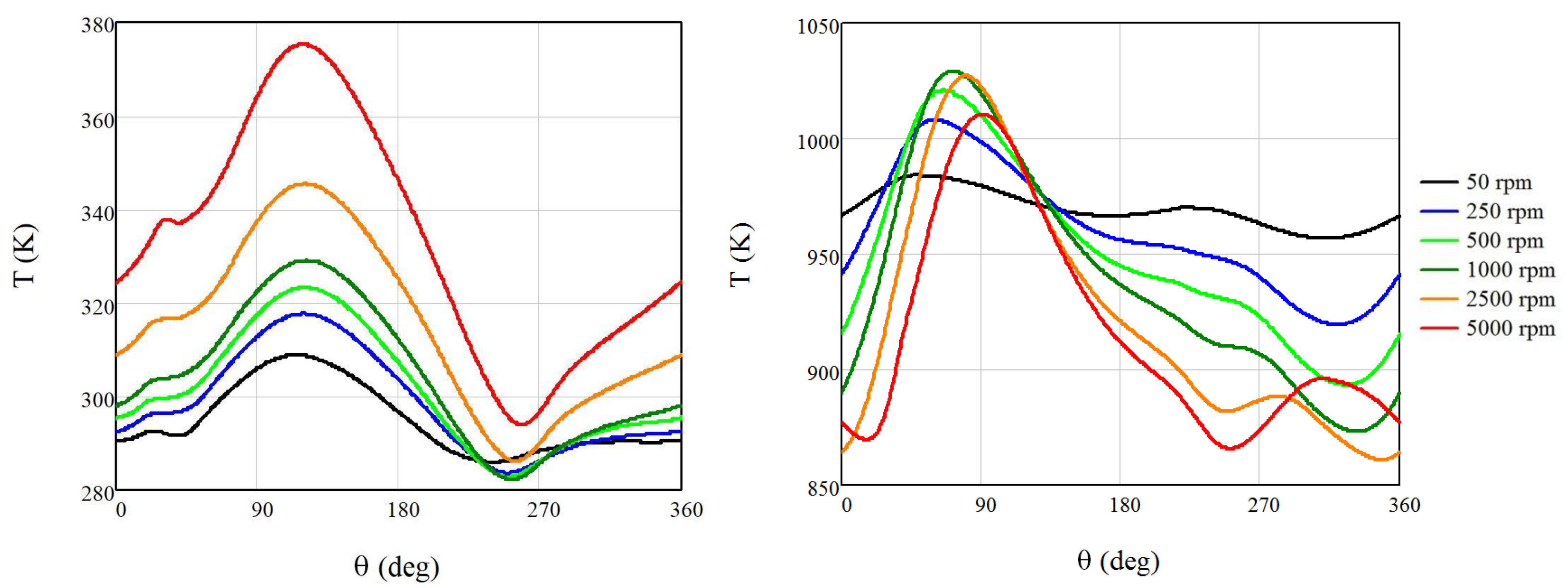
In
Figure 2, the temperature fluctuations in the regenerator are displayed against the point of the cycle (corresponding to an angle, defined as the one used in the UDFs (user-defined functions) that govern the movement of the piston). This is presented for different rotational speeds based on the parametric simulations of the apparatus. It is seen that the higher the rotational speed, the greater the divergence of the temperature from the mean temperature of the cycle. This showcases the validity of the model, as it is displayed that the cycle behaves less like the isothermal model of a Stirling engine and more like the isentropic model the higher the rotational speed. This fact occurs due to the limited time that the working medium has to exchange heat in the heater and the cooler, thus leading to its temperature affecting more in the cases where the rotational speed is higher, which is in agreement with the literature [
9,
21,
22]. Also, it can be seen that the cycles are periodic, which is because these are all steady-state cycles after the machine has converged to steady state. In this work, only steady-state phases of the machine are to be studied, and therefore, this periodical behavior is seen in all the graphs.
In
Figure 3, the temporal evolution of the gas temperature within the cooler and heater is presented. The variation range of the temperature expands as the rotational speed increases. For low angular speeds (50 rpm), the gas temperature in the heat exchangers could be approximated as constant. Notably, the average gas temperature in the cooler rises as the rotational speed increases, whereas in the heater, the average temperature initially increases between 50 and 2500 rpm and stabilizes.
By understanding the behavior of the temperature and how it fluctuates under the different rotational speeds, the outcomes of this speed differentiation are made clear, showcasing the greater divergence from the mean temperature as the rpm increases. This is an important finding for multiple reasons. First of all, this temperature description in regards to the rpm provides the opportunity to calculate the optimal working conditions of the apparatus (something that will be showcased through the efficiency-to-rpm graphs). Additionally, these behaviors of the temperatures serve as verification of the results’ trends, as they seem to follow the expected trend lines. While direct validation is not possible, as no experimental data are available for a comparable apparatus, the fact that as the rpm increases the model seems to be reaching further away from the isothermal description and going more towards the adiabatic one is something that depicts its correct behavior [
19,
22,
23].
In addition, in
Figure 2 and
Figure 3, it can be seen that the cycle has already converged. The presented behaviors are for the steady state of the system and something that can be seen by observing the values and the derivatives of the equivalent graphs. Event at higher rpm, the cyclic behavior of the system is conserved, although as the rpm rises, the values of the temperatures experience very abrupt changes, leading to a decrease in the overall efficiency as it will be shown in the equivalent efficiency-to-rpm and power-to-rpm graphs.
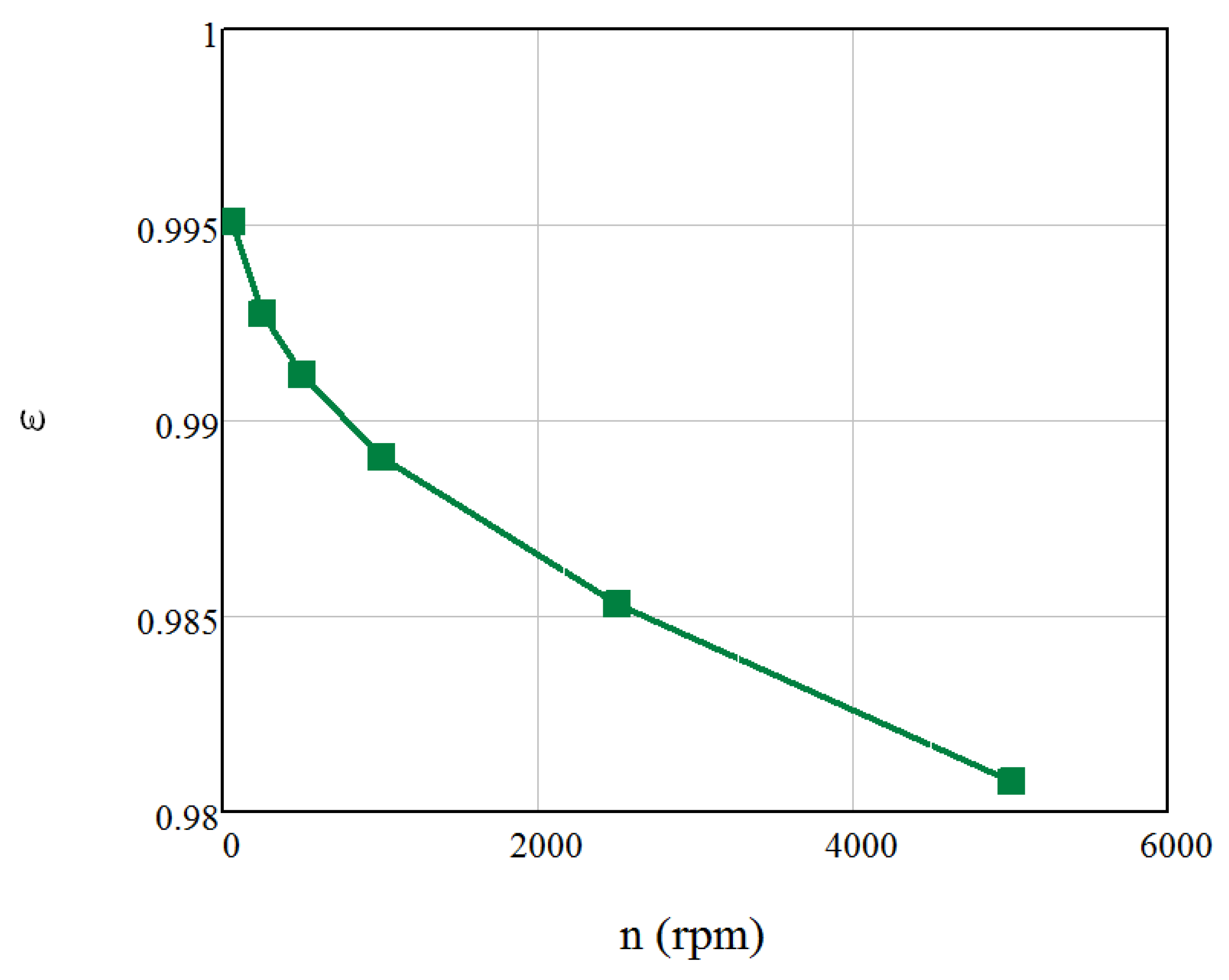
The efficiency of the regenerator for the examined rotational speeds is presented in
Figure 4. As the rotational speed increases, the efficiency of the regenerator declines. It is seen that while a decline is observed in the efficiency of the regenerator, the change is not significant. The overall values come to an agreement with the literature, and given that the efficiency is something that is mostly attributed to the thermal properties of the regenerator, large differentiations of the efficiency values are not to be expected, and the observed decline is marginal.
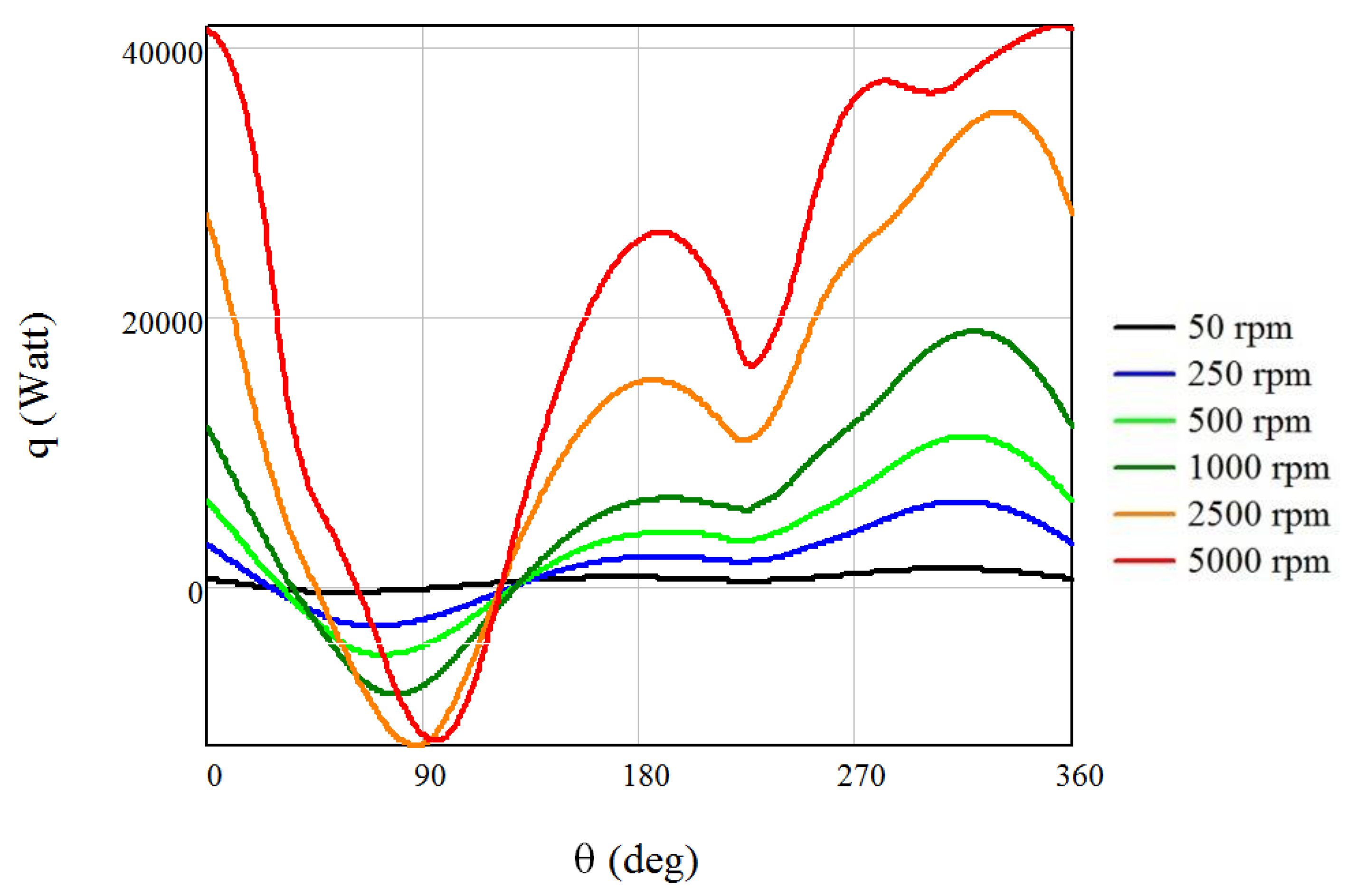
Figure 5 depicts the fluctuations in heat flux per rotational degree throughout the engine operational cycle at varying rotational speeds. The heat flux exchanged with the environment exhibits a substantial increase with the increasing rotational speed. It is worth mentioning that the heat flux is calculated by multiplying the per-degree heat exchange rate by the frequency. As the frequency ratios significantly exceed the corresponding ratios of per-degree heat transfer values, the heat flux in the heater experiences a considerable augmentation with the rotational speed.
Figure 6 illustrates the distribution of heat transfer rates at the heater at two different time intervals for four rotational speeds. The extreme values of heat flux do not exhibit a proportional change with the rotational speed. The distribution of heat flux with angle remains relatively consistent with the angular velocity, except for the slowest machine (50 rpm). As the angular velocity increases, the spatial distribution of the heat flux on the heater wall surface becomes more uniform. Particularly for the slow speed engine, at 90 degrees, heat is expelled from a majority of the heater wall, while heat is absorbed through the tubes connecting the heater ring to the regenerator or expansion chamber. Furthermore, there exists a variation in heat flux values between different sections of the heater for the same angular velocity and time, with this difference becoming more prominent at lower rotational speeds.
Figure 7 presents the heat transfer distribution within the cooler. At 90 degrees, there is heat dissipation from the entire cooler wall, while at 270 degrees, heat is absorbed from the cavity walls and expelled from the tube walls. The spatial disparity in the values of heat exchange becomes more noticeable at lower rotational speeds.
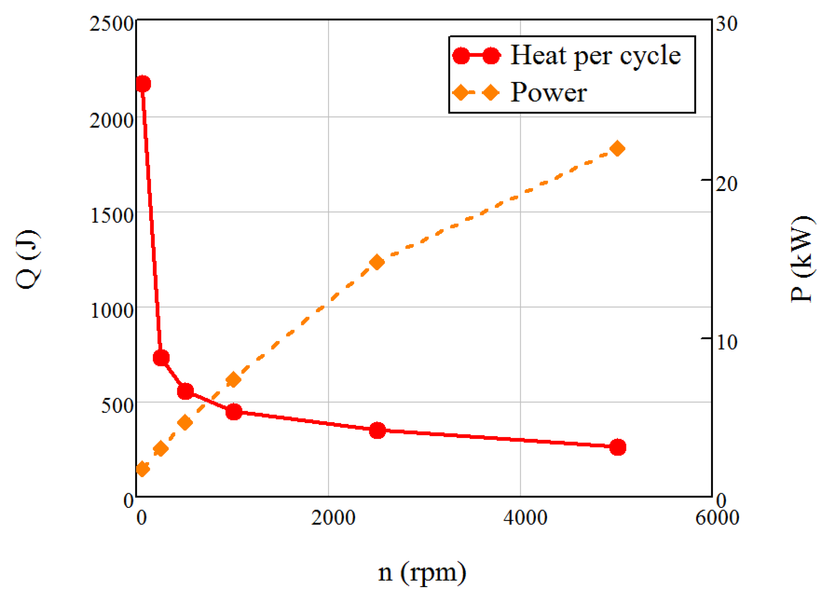
Figure 8 shows the relationship between the rotational speed and the absorbed heat in the system. The absorbed heat experiences a significant decrease as the rotational speed increases from 50 to 250 rpm. However, for further increases in rotational speed, the rate of decrease diminishes. Due to the corresponding changes in heat per cycle, the absorbed power increases with the rotational speed at a decreasing rate.
At low rotational speeds, the time interval between consecutive cycles substantially increases, resulting in higher heat losses. As these thermal losses remain relatively constant for different rotational speeds, the longer duration leads to an increase in energy loss per cycle. The significant heat loss at low rotational speeds amplifies the heat input and heat dissipation in the system.
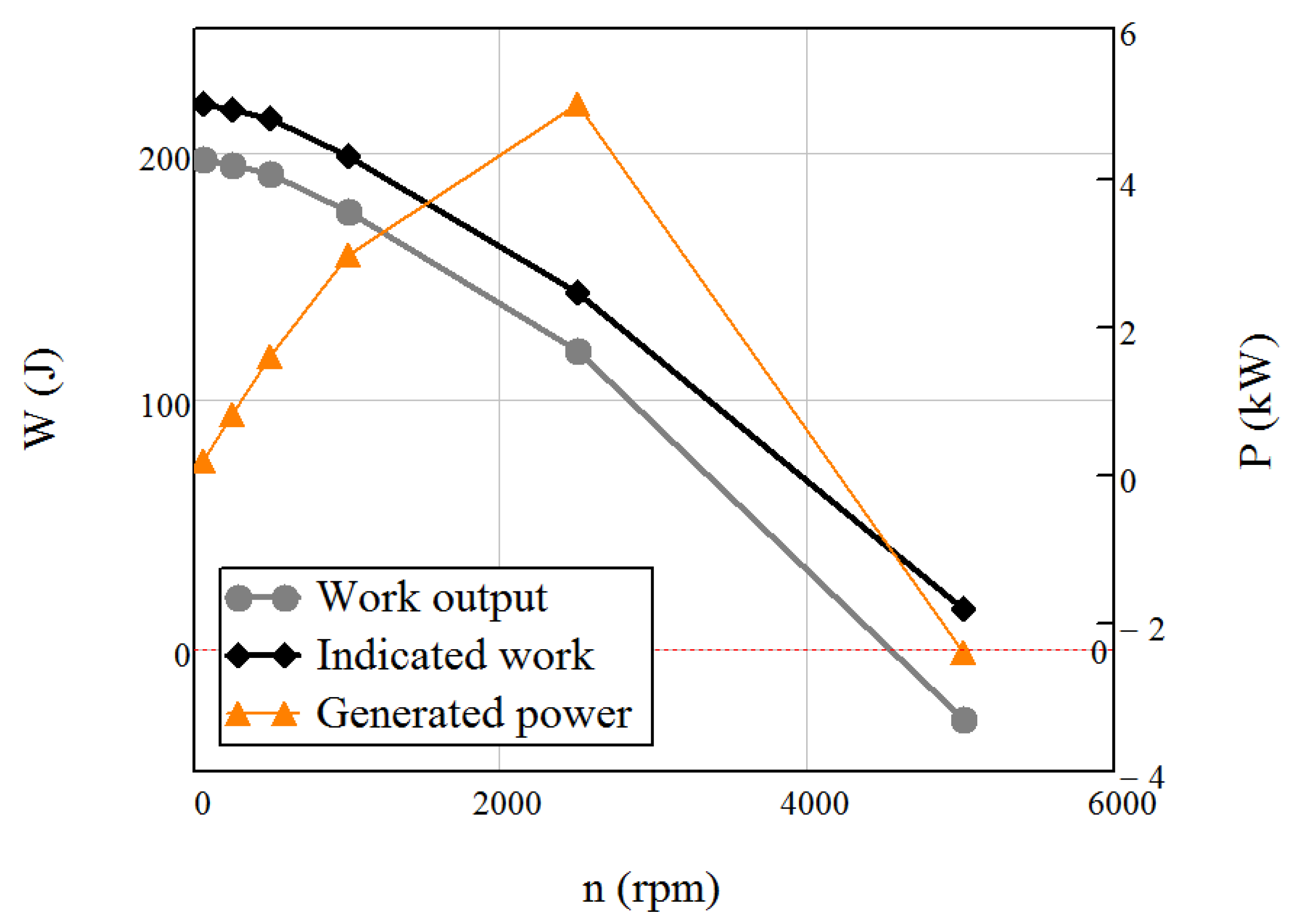
As the rotational speed increases, the indicated work of the machine exhibits a decrease primarily caused by the rise in pressure drop experienced by the working fluid within the machine as shown in
Figure 9. The pressure drop within the engine increases with the speed of rotation at an increasing rate. The decline in the work output becomes more pronounced at higher rotational speeds, mainly due to the significant increase in losses within the kinematic mechanism, particularly for speeds exceeding 2500 rpm. At a rotational speed of 5000 rpm, the work output becomes negative, indicating that the machine requires external work input to operate. The corresponding variation in power generated is also depicted. The power output reaches its maximum value at a rotational speed of 2500 rpm.
Figure 10 shows that the engine achieves its maximum efficiency at a rotational speed of 1000 rpm. At lower speeds, the efficiency is compromised due to the high heat requirement. However, as the rotational speed increases, the reduction in heat requirement surpasses the reduction in work, resulting in an improvement in efficiency. Between 1000 and 2500 rpm, the rate of reduction in work produced exceeds the corresponding rate of reduction in heat demand, leading to a 6 % decrease in efficiency. After the 2500 rpm range, there is a significant decrease in both the efficiency and the power output. For this reason, the operation of such an apparatus above 2500 rpm is not recommended, as given the values of the
Figure 8 and
Figure 10, it can be seen that at very high rpm ranges, the outputs of the machine reach negative values.
The optimal range of rotational speeds for the machine’s operation lies between 1000 and 2500 rpm. The specific range within this interval is chosen based on whether the goal is to maximize the power output or optimize efficiency. Operating the machine between 500 and 1000 rpm yields satisfactory efficiency but with low power output. On the other hand, operating below 500 rpm or above 2500 rpm is uneconomical, as it results in a combination of low power output and low efficiency. In addition, operating in this range leads to a system with lesser temperature fluctuations, something that would be beneficial in cases where such an apparatus is paired within machinery within a greater thermal system.
Equation (2) was produced by fitting to the values of the Nusselt number as given by the simulation. The fitting procedure was performed using an artificial intelligence algorithm for the calculation of the coefficients as well as providing results for 67 possible different function types, from which the provided was chosen. The provided equation with the equivalent coefficients has an so it is more than sufficient for a very accurate depiction of the Nusselt behavior based on the data.
Obtaining the Reynolds number value through CFD analysis at different angular velocities, a correlation is established, using rotational speed as the sole independent variable. This correlation is presented at
Figure 11. Consequently, the Nusselt number exhibits an upward trend with increasing rotational speed, representing the ratio of convective heat transfer to conductive heat transfer. At lower rotational speeds, heat conduction significantly influences the regenerator. However, as the rotational speed rises, there is a notable improvement in the convective heat transfer between the working medium and the heat exchanger.
Overall, it is seen that the optimal point for the operation for the apparatus is at 1000 rpm for the efficiency and 2500 rpm for the power output. Therefore, it is recommended that any such machine designed and built is to be operated between these rpm values. Also, when the rpm rises further than the 2500 optimal case and goes towards the 5000 limit of the model, the fluctuations of the temperatures become more extreme. This phenomenon has a significant effect on the efficiency, and in a real scenario, these fluctuations would lead to an apparatus that is more difficult to construct and operate, especially if it is to be coupled with other thermal systems.
4. Conclusions
In this article, a thorough investigation of the performance of a -type Stirling engine was conducted through a parametric analysis of its rotational speed. The concluding statements present a concise overview of the key elements explored in the current study.
As the rotational speed increases, the temperatures of the regenerator and the heater are seen to diverge more significantly from their equivalent mean temperatures. For the heater at 50 rpm, a divergence of around 5% is observed in the temperature, while at 5000 rpm, the divergence is of the range of 14%.
The cooler’s average gas temperature rises, while that of the heater stabilizes after an initial increase between 50 and 2500 rpm. For the cooler, the dependency of the temperature to the rpm leads to a 18.5% increase to its max temperature values.
With an increase in rotational speed, there is a slight decline in the efficiency of the regenerator, although the decrease observed is minimal (the total decrease from 50 to 5000 rpm is 0.015% as seen in
Figure 4).
With increasing the angular velocity, the heat flux on the heater wall surface becomes more uniformly distributed. On the surfaces of the cooler, the disparity becomes more apparent at reduced speeds, as seen in the temperature depictions of
Figure 6.
The peak power output is achieved when the rotational speed reaches 2500 rpm, while the engine attains its highest efficiency at a rotational speed of 1000 rpm.
A correlation between the rotational speed and the Nusselt number is proposed based on the results of the CFD analysis, and it is seen that the Nusselt number almost linearly increases with the increase in the rpm.
Summing up, the results of this work showcase the ability of such a computational model to be able to describe the behavior of the proposed Stirling engine in different working conditions, allowing for a more in-depth understanding of both its total outcomes and its inner thermofluid behaviors. Through this research, by performing a parametric analysis, the optimal working conditions are found, and, as such, in any further studies these would be the working conditions that are proposed, for optimal use, to be implemented in any real case scenarios. Lastly, by being able, through the parametric analysis to understand the behaviors of the variables, equations for the predictions of some of the unit-less fluid mechanics numbers (such as the Nusselt or Reynolds) are possible, therefore giving the ability to understand even theoretically what some of the limit conditions under which this machine can operate are, without the need for a full simulation.


